

Page 1

DW9952K
DW9952K-2
DW9955K
service manual
Note:
1. The scheme of DW9952K-2is totally the same with that of DW9952K, only the model of audio A/D
conversion IC is different, DW9952K-2 adopts Cs5340, but DW9952K adopts CS5333.
2. The scheme of DW9955K is totally the same with that of DW9952K-2, only that DW9955K
changes hard disk into 250G.
Page 2

Catalog
Chapter One About Maintenance
1.1 Safety precautions
1.1.1 Power supply
1.1.2 Precautions for antistatic
1.1.3 Precautions for laser head
1.1.4 About placement position
1.2 Maintenance method
1.2.1 Visualized method
1.2.2 Electric resistance method
1.2.3 Voltage method
1.2.4 Current method
1.2.5 Cutting method
1.2.6 Element substitution method
1.2.7 Comparison method
1.3 Required device for maintenance
1
1
1
1
1
2
2
2
2
2
2
2
3
3
3
Chapter Two Functions and Operation Instructions
2.1 Features
2.2 BASIC INFORMATION
2.2.1 Illustration of the Front Panel
2.2.2 Illustration of the Rear Panel
2.2.3 Illustration of the VFD
2.2.4 Illustration of the Remote Control
2.3 Accessories
2.4 SYSTEM SETUP
2.4.1 Operation Interface and General Steps
2.4.2 Recording Setup
2.4.3 Video Setup
2.4.4 Audio Setup
2.4.5 Language Setup
4
4
5
5
5
5
6
7
7
7
8
9
10
11
Page 3

2.4.6 Date/Time Setup
12
2.4.7 Preferences Setup
2.4.8 Time Shift Setup
2.4.9 Channel Scan Setup
2.5 PLAYBACK MODE
2.5.1 DVD/VCD/CD Playback
2.5.2 HDD Playback
2.6 FILE OPERATION
2.6.1 File Copy Menu
2.6.2 Playback Control Menu
2.7 RECORDING MODE
2.7.1 Summarization
2.7.2 Viewing the inputted source
2.7.3 Recording to DVD
2.7.4 Record to HDD
2.7.5 Dubbing
12
13
14
16
16
21
21
21
22
23
23
23
24
25
26
2.8 TIME SHIFT MODE
2.8.1 Summarization
2.8.2 How to Receive the TV Program
2.8.3 A Time Shifting
2.8.4 Summarization
2.8.5 Operation Steps
2.9 Playing and processing the disc recorded by this unit
2.9.1 To Browse the Contents of the Disc and Select one Title to Play
2.9.2 Edit Title
2.9.3 Erasing Title
2.9.4 Copy
2.9.5 Rename Title
2.9.6 Overwrite Title/ Append Title/ Overwrite Disc
2.10 EDITING MODE
2.10.1 Summarization
26
26
26
26
27
27
29
29
29
30
30
30
30
30
30
2.10.2 Editing Recorded Disc
2.10.3 Menu Explanation
2.10.4 Operation Steps
2.10.5 Exiting the Editing Mode
31
31
31
32
Page 4

2.10.6 Editing Hard Disc
32
2.10.7 Sorting
2.11 DISC OPERATION
2.11.1 Summarization
2.11.2 Entering the Disc Operation Mode
2.11.3 Operations
2.11.4 Exiting the Disc Operation Mode
2.12 USB MODE
2.12.1 Summarization
2.12.2 Operations
2.12.3 Exiting the USB mode
2.13 SPECIFICATIONS
Section One Principle of the Player
Chapter Three Principle and Servicing
3.1.1PCB board composing figure of the player
34
34
34
34
34
35
35
35
35
35
37
39
39
39
3.1.2 Block diagram of the player
3.1.3 Function introduction to IC of the player
Section Two Unit Circuit Principle
3.2.1 Working mode introduction
3.2.2 Audio output circuit
3.2.3 Video output circuit
3.2.4 Audio input circuit
3.2.5 Video input circuit
3.2.6 Reset circuit
3.2.7 IIC bus control circuit
3.2.8 Voltage stabilizing circuit
3.2.9 USB jack circuit
3.2.10 DV jack circuit
3.2.11 IDE jack circuit
3.2.12 Control panel
40
41
42
42
43
45
46
48
49
51
53
54
54
55
56
3.2.13 AV circuit
3.2.14 MIC circuit
3.2.15 Power circuit
Section Three Servicing Cases
57
62
64
66
Page 5

3.3.1 Servicing cases
66
3.3.2 Troubleshooting flow chart
Section Four Servicing Parameters
3.4.1 Signal waveform diagram
3.3.2 Key point voltage
Section Five Function Introduction to IC
Chapter Four Disassembly and Assembly Process
Chapter Cinque PCB board & Circuit diagram
Section One PCB board
Section Two circuit diagram
Chapter six BOM List
72
86
86
99
101
132
133
133
141
164
Page 6

Chapter One About Maintenance
1.1 Safety precautions
1.1.1 Power supply
When maintenance personnel are repairing DVD players, he should pay special attention to the
power board with 220V AC and 330V DC which will cause hurt and damage to persons!
1.1.2 Precautions for antistatic
Movement and friction will both bring static electricity which causes serious damages to integrated
IC. Though static charge is little, when a limited quantity of electric charge is added to large-
scaleintegrated IC, as the capacitance is very small in the meantime, now the integrated IC is very much
easy to be struck through by static electricity or the performance will decrease. Thus static electricity
prevention is of extraordinary importance. The following are several measures to prevent static
electricity:
1. Use a piece of electric conduction metal with the length of about 2 metres to insert into the earth,
and Fetch the lead wire from the top of the surplus metal and connect to the required static electricity
device. The length and depth of the metal embedded under the earth should be determined according to
the wettability of the local soil. For humid places, it may be shorter, and longer and deeper for dry places.
If possible, it can be distributed and layed in terms of “#” shape.
2. On operating table-board, the antistatic table cushion should be covered and grounded.
3. All devices and equipments should be placed on the antistatic table cushion and grounded.
4. Maintenance personnel should wear antistatic wrist ring which should be grounded.
5. Places around the operating position should also be covered with electric conduction cushion or
Painted with antistatic paint.
1.1.3 Precautions for laser head
1. Do not stare at laser head directly, for laser emission will occur when laser head is working, which
will Hurt your eyes!
2. Do not use wiping water or alcohol to clean laser head, and you may use cotton swab.
- 1 -
Page 7

1.1.4 About placement position
1. Never place DVD player in positions with high temperature and humidity.
2. Avoid placing near high magnetic fields, such as loudspeaker or magnet.
3. Positions for placement should be stable and secure.
1.2 Maintenance method
1.2.1 Visualized method
Directly view whether abnormalities of collision, lack of element, joint welding, shedding welding,
rosin joint, copper foil turning up, lead wire disconnection and elements burning up among pins of
elements appear. Check power supply of the machine and then use hands to touch the casing of part of
elements and check whether they are hot to judge the trouble spot. You should pay more attention when
using this method to check in high voltage parts.
1.2.2 Electric resistance method
Set the multimeter in resistance position and test whether the numerical value of resistance of each
point in the circuit has difference from the normal value to judge the trouble spot. But in the circuit the
tested numerical value of resistance is not accurate, and the tested numerical value of integrated IC's
pins can only be used for reference, so the elements should be broken down for test.
1.2.3 Voltage method
Voltage method is relatively convenient, quick and accurate. Set the multimeter in voltage position
and test power supply voltage of the player and voltage of a certain point to judge the trouble spot
according to the tested voltage variation.
1.2.4 Current method
Set the multimeter in current position and test current of the player of a certain point to judge the
trouble spot. But when testing in current method, the multimeter should be series connected in the
circuit, which makes this method too trivial and troublesome, so it is less frequently used in reality.
1.2.5 Cutting method
Cutting method should be combined with electric resistance method and voltage method to use.
This method is mainly used in phenomena of short circuit and current leakage of the circuit. When
cutting the input terminal voltage of a certain level, if voltage of the player rises again, it means that the
trouble lies in this level.
- 2 -
Page 8

1.2.6 Element substitution method
When some elements cannot be judged good or bad, substitution method may de adopted directly.
1.2.7 Comparison method
A same good PC board is usually used to test the correct voltage and waveform. Compared these
data with those tested through fault PC board, the cause of troubles may be found.
Through the above maintenance method, theoretical knowledge and maintenance experience, all
difficulties and troubles will be readily solved.
1.3 Required device for maintenance
Digital oscillograph ( 100MHE)
TV set
SMD rework station
Multimeter
Soldering iron
Pointed-month pincers
Cutting nippers
Forceps
Electric screw driver
Terminals connecting cord
Headphone
Microphone
- 3 -
Page 9

Chapter Two
Functions and Operation Instructions
2.1 Features
# Utilizing MPEG- Real-Time encoding and decoding technology, capable of directly recording TV and
other external program sources on DVD+R, DVD+ RW discs and HDD
# Capable of recording your favourite video tapes into DVD+R/RW
# Built-in DV (i. LINK/IEEE1394) input jack enables fully digital high fidelity recording of digital video
camcorder signals
# Progressive scan outputs to produce stabler and clearer pictures without flicker
# Built-in 5.1CH Dolby Digital surround decoder, separate 5.1CH outputs, 2CH Dolby outputs, optical
and coaxial output for digital audio
# 24bit audio DAC to produce perfect acoustic fidelity
# With normal DVD playback function, capable of playing DVD, SVCD, VCD, CD, MP3, JPEG, DVD+R
and DVD+RW discs
# Recorded discs can be played on normal DVD players
# Single-side discs DVD+R/DVD+RW (4.7GB) are capable of 6 hours video recording
# Supporting 4 recording modes: HQ, SP, EP, SLP
# OTR function enables one-touch recording, convenient to select the length of recording time
# Manual/automatic insertion of chapter mark
# Chapter hiding, disc locking to the recorded discs (DVD+RW) and renaming the titles are available
# Title index pictures of recorded disc (DVD+RW) can be select freely
# Multi-dubbing, multi-angle, multi-subtitle for selection
# Built-in TV tuner with TV reception function enables automatically channels scanning
# With AV terminal, S-Video, DV (i. LINK/IEEE1394) and antenna input terminals, double-SCART
terminal convenient to record various program sources
# With composite video, component/progressive-scan video output terminals and TV antenna output
terminals, convenient to connect with various TV sets
# Intelligent preset timing recording function prevent you from missing any wonderful programs
# Recording and output system is optional between PAL/NTSC system
#
Simultaneous video recording and playback. play a previously recorded program while another
program is being simultaneously recorded
# Select program(s) from HDD and copy them to DVD+R/RW and you can catch a TV program at one
time
Select program(s) from DVD+R/RW and copy them to HDD and you can watch a TV program at one
#
time
#
Time shifting function allows pausing the live TV broadcast for up to 360 minutes
# Renaming, Deleting, Splitting, Segmenting, combining and Locking program(s) on HDD are available
# Playback MP3 music and slide show JPEG picture on the USB
- 4 -
Page 10
# Super wide range of operating power supply: ~100V -240V, 50/60Hz, standby power consumption
3W
# Software intelligent upgrading function, after upgrading software, the HDD space will be emptied
# Dual SCART: one for input, another for output
# Dual Kara OK function
# PIP function
2.2 BASIC INFORMATION
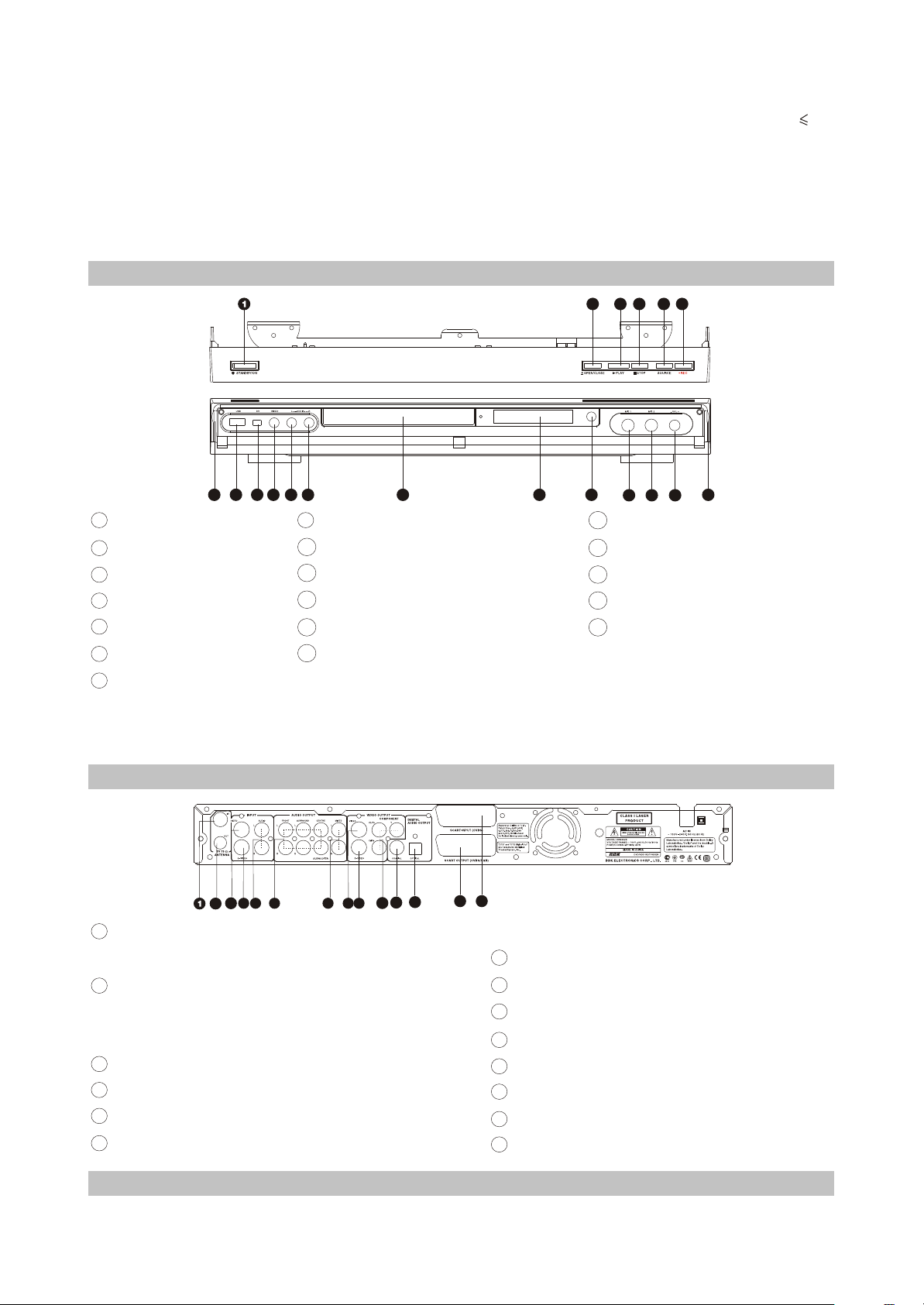
2.2.1 Illustration of the Front Panel
6
5
3
4
18
7
8
9
14
Left audio channel input terminal
15
Front Video input terminal
16
DV input terminal
17
USB input terminal
18
Open the terminal protection
cover here
1
STANDBY/ON button
2
OPEN/CLOSE button
3
PLAY button
4
STOP button
5
SOURCE button
6
REC button
7
VOL KNOB
2
16
17
18
14
15
13
8
MICPHONE 2
9
MICPHONE 1
10
Infrared remote sensor
11
VFD display window
12
Disc tray
13
Right audio channel input terminal
12 11
10
# The function of buttons on the front panel is the same with that of the corresponding ones on the
remote control.
# The input terminals on the front panel can only be seen when the protection cover is opened.
2.2.2 Illustration of the Rear Panel
13
2
1
TV TUNER input terminal
6
4
5
3
7
8
9
# The antenna cable plug is inserted here
2
TV TUNER output terminal
# This terminal is directly connected with the TV
TUNER Input Terminal inside this unit
3
Rear Video input terminal
4
Rear S-Video input terminal
5
Rear L/R channel audio input terminals
6
5.1CH output terminals
1212
11
10
14
7
L/R channel audio output terminals
8
COMPOSITE VIDEO output terminal
9
S-VIDEO output terminal
10
COMPONENT VIDEO output terminal
11
COAXIAL output terminal
12
OPTICAL output terminal
13
CVBS/RGB and Audio output terminal
14
CVBS and Audio input terminal
2.2.3 Illustration of the VFD
- 5 -
Page 11
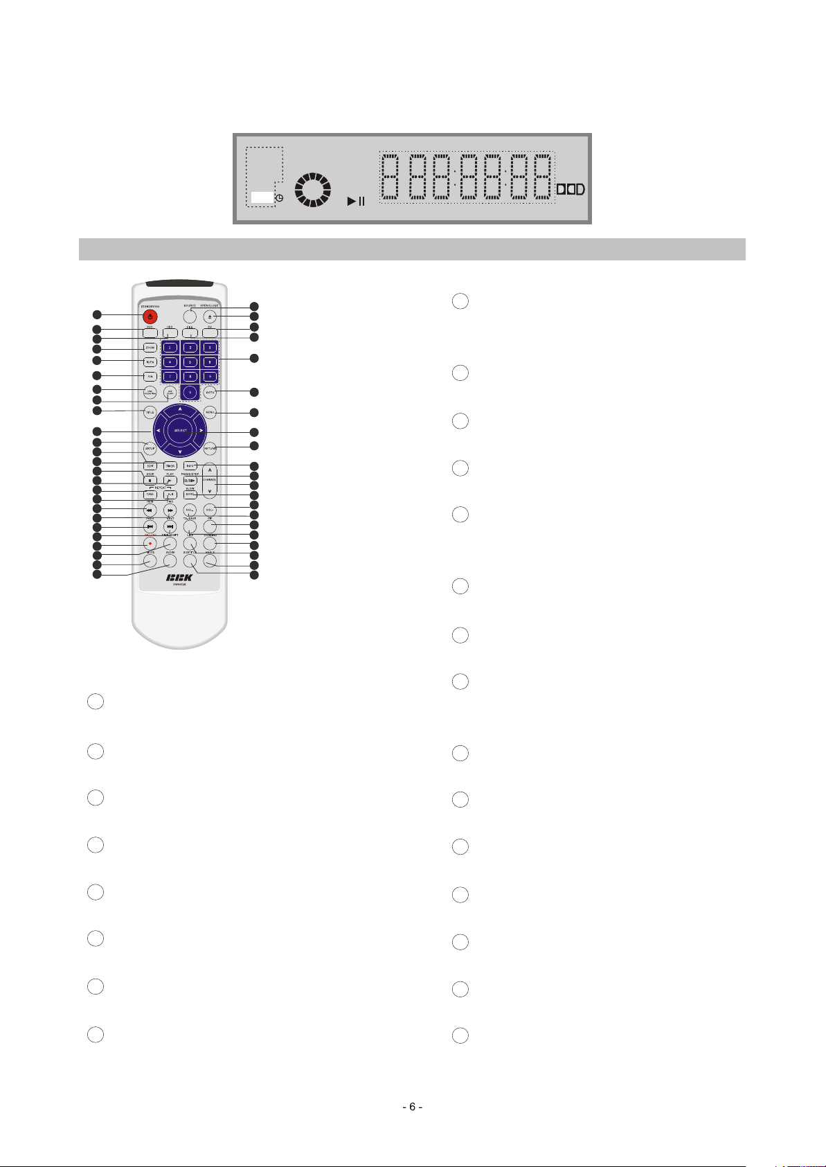
The look of VFD is shown as the following figure:
DVD
SVCD
MP3
REC
PBC
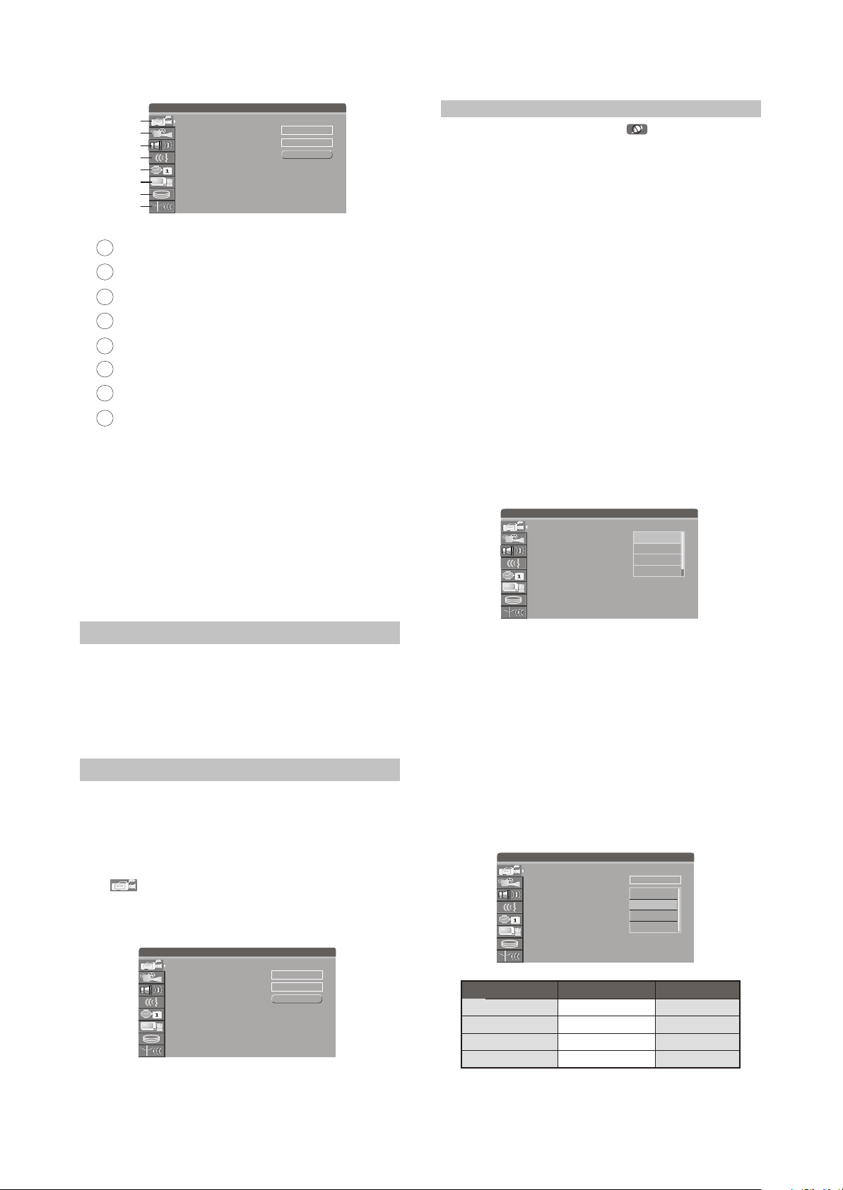
2.2.4 Illustration of the Remote Control
1
2
3
4
5
6
7
8
9
10
11
12
13
14
15
16
17
18
19
20
21
22
23
24
25
46
45
44
43
42
41
40
39
38
37
36
35
34
33
32
31
30
29
28
27
26
1
STANDBY/ON button
Switch between standby state and working
state
2
DVD button
Switch to DVD mode
3
HDD button
Switch to HDD mode
4
ZOOM button
Enlarge the DVD/VCD/JPEG picture
5
IS/PS button
The progressive scan and interlaced scan
conversion
6
P/N button
16
REPEAT 1/ALL button
Repeat playback
REPEAT A-B button
17
Repeat A-B segment playback
18
REW button
Fast backward play
19
FWD button
Fast forward play
20
PREV button
Skip backward
21
NEXT button
Skip forward
22
RECORD button
Record the external signals
23
TIME-SHIFT button
Watch TV and display time shifting
The PAL/NTSC TV output system conversion
7
DISC OPERATION button
Enter the disc operate mode
8
ADD/CLEAR button
# Add/Clear the content items in the list window
# Clear the wrong input numbers
9
TITLE button
Display DVD titles menu
10
CURSOR button
Move the cursor
11
SETUP button
System setup
12
EDIT button
Enter the edit mode
13
TIMER button
Enter the timing record setup
14
STOP button
Stop playing/recording
15
PLAY button
Play a disc
Page 12

MUTE button
24
Mute the sound
25
AUDIO button
PAUSE/STEP button
36
Pause or Play frame by frame
37
INFO button
Switch the audio channel
26
SUBTITLE button
Change subtitle languages
27
ANGLE button
Change camera angles
28
LIVE button
From TV time shift cover to TV live
29
DUBBING button
Copy program(s) from HDD to recordable disc
30
TS-SAVE button
Save the time shift contents to HDD
31
PIP button
Switch to PIP mode
32
VOL- button
Decrease volume
33
VOL+ button
Increase volume
34
SLOW/SORT button
Display/hide information menu
38
RETURN button
Back to the previous menu
39
SELECT button
Confirm the selected item
40
MENU button
# Display the disc menu
# Open/Close PBC
41
GOTO button
Play from the desired location
42
NUMBER 0-9 button
43
FILE button
Switch to file operation(Playback and copy file
onto
HDD optical drive and USB device)
44
DV button
Switch to DV status
45
OPEN/CLOSE button
Scan in slow forward or sort the HDD titles
35
CHANNEL /CHANNEL button
Change the TV channel up/down
Open or close the disc tray
46
SOURCE button
Switch external input signal sour
2.3 Accessories
Mini-DV cable
75 TV coaxial cable
audio/video cable
remote control
7# batteries
warranty card
owner's manual
1PCS
1PCS
1PCS
1PCS
2PCS
1PCS
1PCS
2.4 SYSTEM SETUP
In order to satisfy different kinds of consumers and because of the outfits with different performanc,
this unit is equipped with various functions. You can proceed the system setup to meet your needs and
cooperate with your outfits.Certainly you may use the default settings to satisfy your basic requirements.
2.4.1 Operation Interface and General Steps
This section introduces the operation interface and general steps of the system setup.
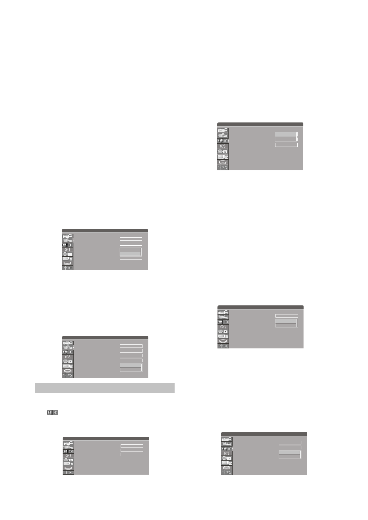
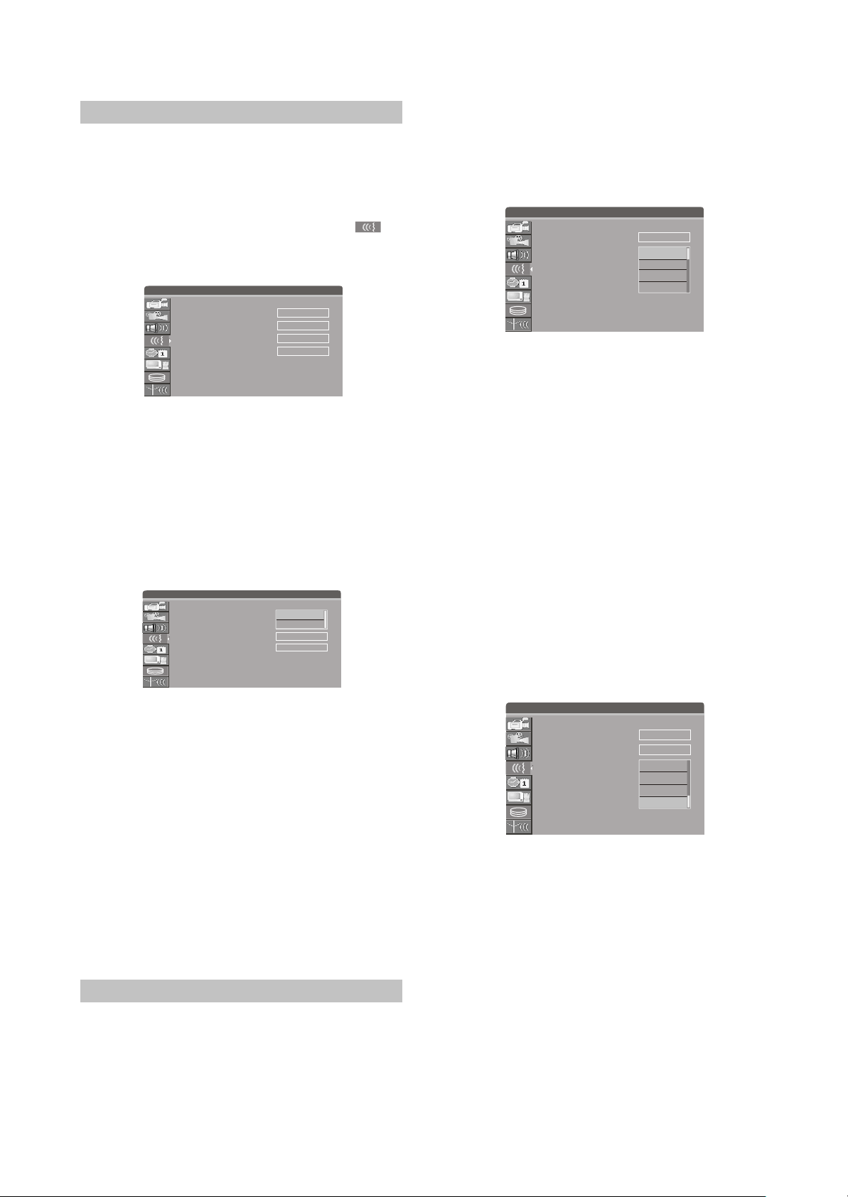
1.Press [Setup] button to enter system setup mode. Then the TV screen displays the system setup
control menu, which is shown in the following:
#If the system displays , it means the System Setup Mode can not be entered in current mode, so
please exit this mode first.
#The meanings of the icons are as follows:
Page 13
SETUP MENU-RECORDING
1
2
3
4
5
6
7
8
1
Recording Setup
2
Video Setup
3
Audio Setup
4
Language Setup
5
Date/Time Setup
6
Preferences Setup
7
Time Shift Setup
8
Channel Scan Setup
2.Select the desired item on the control bar by
using [5], [6 ] buttons, and then press [Select]
Auto Chapter Marker
Record Quality
Timer Setting Menu
System Setup Menu
¢Ù
¢Ú
¢Û
¢Ü
¢Ý
¢Þ
¢ß
¢à
5 minutes
SP
OK
button to enter the corresponding setup
submenu .
3.In the submenu,operate the relative controllers
by direct buttons and the [Select] button to
fulfill the corresponding setup.
4.Press the [Return] button to return to the
previous menu, or press the [Setup] button to
exit.
NOTES
#The steps above are general operations. Some
setup may not need a certain step, or need
more steps.
#Please proceed the system setup in tray out or
no disc status, otherwise some setup may not
be proceeded.
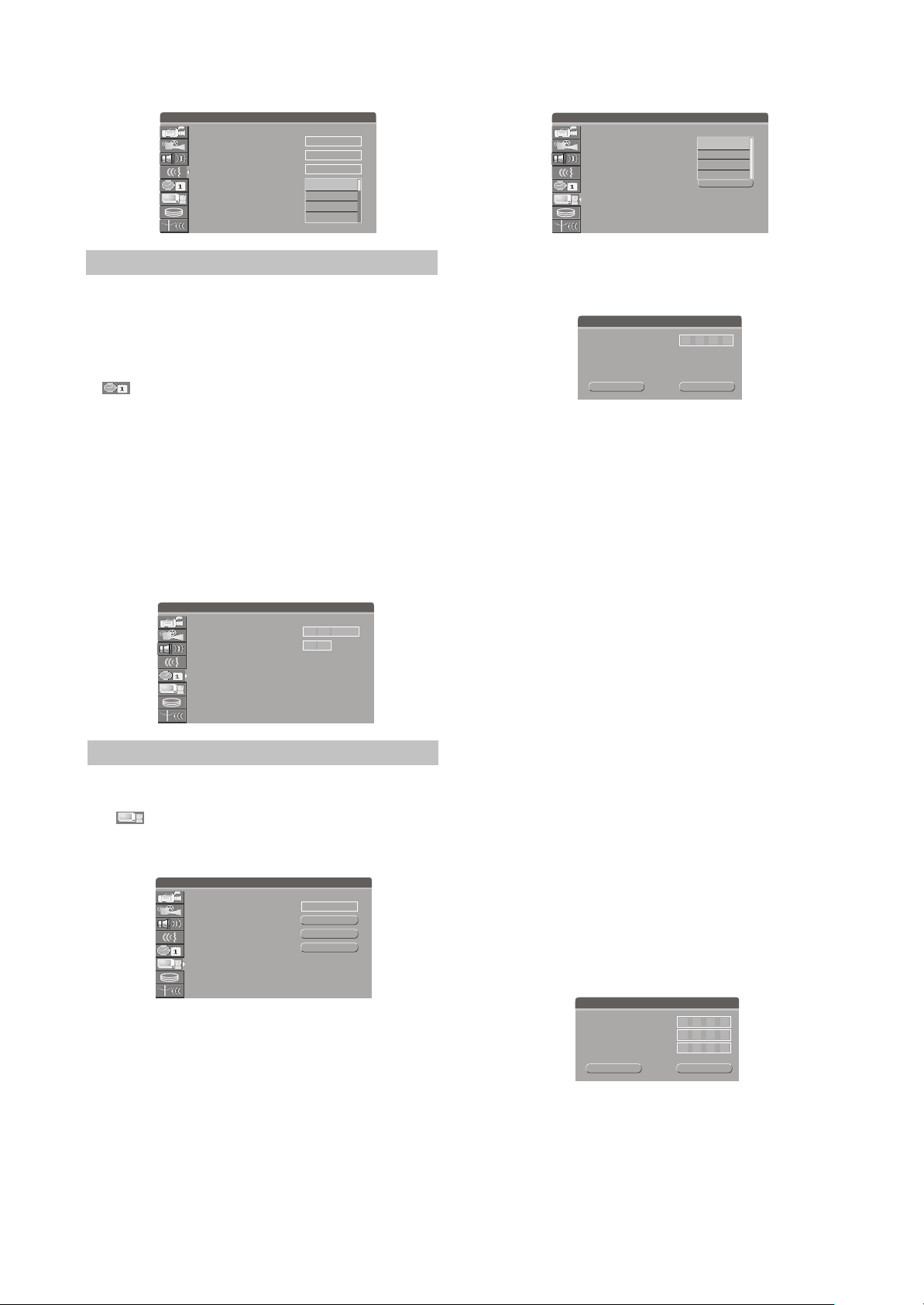
2.4.2 Recording Setup
After finishing the settings introduced in this
chapter, when recording, the values you set will
become the default values of the correlative
items.
1.In the system setup control menu, select item
" " by [5], [6 ] buttons and then press
[Select] button to enter recording setup menu.
The screen displays:
NOTE
#If the TV screen displays " ", when
pressing [5],[6]button, it may indicate that the
current activated menu will not be the system
setup control menu. Please press [Return]
button once or more to activate the system
setup control menu.
Auto Chapter Marker Setup
1.In the record setup menu, select item "Auto
chapter marker" by [5], [6] buttons, press
[Select] button, and then a pop-up menu will
appear:
2.Select the proper value by [5], [6] buttons, and
then press [Select] button to confirm.
#This setup is used to make sure whether insert
the chapter
marker automatically when recording.
#If you don't set this item to "OFF", the recorded
contents will be automatically divided into
some chapters with the same length according
to the interval time you've selected.
SETUP MENU-RECORDING
Auto Chapter Marker
Record Quality
Timer Setting Menu
5 minutes
5 minutes
5 minutes
SP
10 minutes
10 minutes
20 minutes
20 minutes
OK
30 minutes
30 minutes
Recording Quality
1.In the record setup menu, select item "Record
quality" by [5], [6] buttons, press [Select]
button, then a list menu will appear.
2.Select the desired value by [5], [ 6] buttons,
and then press [Select] button to confirm.
#Please refer to the "Recording mode -
Recording to DVD - Manual Recording Quality" for the four recording qualities: HQ,
SP, EP, SLP.
#Recording time table:
SETUP MENU-RECORDING
Auto Chapter Marker
Record Quality
Timer Setting Menu
5 minutes
SP
HQ
OK
SP
EP
SLP
SETUP MENU-RECORDING
Auto Chapter Marker
Record Quality
Timer Setting Menu
the record setup menu
5 minutes
SP
OK
- 8 -
Recording mode
HQ (High Quality)
SP (Standard Play)
EP (Extended Play)
SLP (Super Long Play)
4.7GB
DVD+R/DVD+RW
About 1H
About 2H
About 4H
About 6H
160GB HDD
Recording time
About 21H
About 67H
About 133H
About 200H
Page 14

Timer Setting Menu
You can make this unit record automatically
when the preset time is coming. The operation
steps refer to "Timer Setting Mode", please read
carefully the detailed contents of the section
"Timer Setting Mode".
Timer Recording
Quality
Date
Source
1
2
3
4
5
6
£
Press Select to review a scheduled recording or create a
¢¡
new one
¤
Start
End Record
2.4.3 Video Setup
1.Display the system setup control menu.
2.Move the cursor by[5],[6] buttons to select
" " item.
3.Press [Select] button or [4] button to enter the
video setup mode.
SETUP MENU-VIDEO
Video output format
TV aspect ratio
Progressive/Interlaced
SCART output
Preview Type
Video output format
This unit has two video output systems: PAL
and NTSC You can select one of them according
to your TV set specs.
1.Highlight "Video output format" in the video
menu and press [Select] button. A pop-up
menu will appear which is shown as the right
figure.
2.Select the proper option according to factual
requirements.
3.Press [Select] button, then the system will
switch the output format to what you select
right now.
#You can switch the TV output format by
pressing the [P/N] button on the remote
control too.
#Changing the output format may cause no
picture on the TV screen. If this happens, you
can press [P/N] button on the remote control
to restore the output format.
SETUP MENU-VIDEO
Video output format
TV aspect ratio
Progressive/Interlaced
SCART output
Preview Type
PAL
Letter Box
Interlaced
RGB
Static
PAL
PAL
Letter Box
NTSC
Interlaced
RGB
Static
TV aspect ratio
1.In the Video Setup Menu, select item "TV
aspect ratio" by[5], [6] buttons and press
[Select] button, and then the value list will
appear, which is shown as the right figure.
2.Select the suitable value by [5], [6] buttons,
and then press the [Select] button.
#The meaning of each value to be selected of
this item is as follows:
#16 : 9: Applicable to wide screen TV set.
#Pan Scan: Suitable for the common size TV set.
When playing wide screen pictures, left and
right
#Edges of the original pictures are cut off. The
picture will be displayed to full screen.
#Letter Box: Suitable for the common size TV set.
When playing wide screen pictures, black
banners will appear on the top and bottom of
the TV set.
Note
#The playback effect is related to the playing
disc.If a disc is recorded in the aspect ratio of
4:3,the ratio can only be 4:3, no matter which
screen setting you select.
#This setting should conform to the aspect ratio
of the TV set.
SETUP MENU-VIDEO
Video output format
TV aspect ratio
Progressive/Interlaced
SCART output
Preview Type
PAL
Letter Box
Letter Box
Pan Scan
Interlaced
16:9
RGB
Static
Progressive/Interlaced
1.In the video setup menu, use [5], [6] buttons to
select "Progressive / Interlaced" item and
press [Select] button, then a list will appear.
2.Select "Progressive" or "Interlaced".
3.Press [Select] button to fulfill the Progressive /
Interlaced switch.
4.You can also keep on pressing [IS/PS]button
for 3 seconds to perform the Progressive/
Interlaced switching.
SETUP MENU-VIDEO
Video output format
TV aspect ratio
Progressive/Interlaced
SCART output
Preview Type
PAL
Letter Box
Interlaced
Interlace
Progressive
RGB
Static
#The value of this setting must accord with the
scanning mode of the TV, otherwise the TV
screen will display nothing.
- 9 -
Page 15
#Change the output format may cause no picture
on the TV screen. If happen this, please press
[IS/PS] on the remote control to restore the
output format.
#To avoid instability of output signal, please
don't perform "Progressive/Interlaced"
function by component(Y, Cb/Pb, Cr/Pr)
terminal on the rear panel when "SCART
output" item is RGB.
SCART Output
1.In general setup menu, highlight "SCART
output", and press [Select] button, and then a
list will appear.
2.Select "YCbCr / CVBS" or "RGB" in the list and
press [Select] to confirm.
#When using component video output, please
select "YCbCr / CVBS".
#When using SCART output, you may select
according to the fact. But you had better select
the "RGB".
#This setup does not affect the composite video
output.
SETUP MENU-VIDEO
Video output format
TV aspect ratio
Progressive/Interlaced
SCART output
Preview Type
PAL
Letter Box
Interlaced
YCbCr/CVBS
RGB
RGB
Static
Preview Type
1.In the video setup menu, use [5/6] buttons to
select"Preview Type" item and press [SELECT]
button, then a list will appear.
2.Select "Static" or "Dynamic".
3.In HDD title list menu, the preview is static or
dynamic.
SETUP MENU-VIDEO
Video output format
TV aspect ratio
Progressive/Interlaced
SCART output
Preview Type
PAL
Letter Box
Interlaced
RGB
Static
Static
Dynamic
2.4.4 Audio Setup
1.Display the system setup control menu.
2.Move the cursor by[5],[6] buttons to select
" " item.
3.Press [Select] button or [4] button to enter the
audio setup mode.
SETUP MENU-AUDIO
Analog audio output
Digital audio output
LPCM Output
2 CH
RAW
LPCM 48K
Analog audio output
This setting is used to select an analog
audio output format between 2CH analog mix
audio output and Dolby 5.1 CH analog output.
1.Select
"Analog Audio Output" item by [5], [6]
buttons, and press [Select] button, then a popup list will appear:
2.Select the desired value by [5],[6] buttons then
press [Select] button to confirm.
SETUP MENU-AUDIO
Analog audio output
Digital audio output
LPCM Output
2 CH
2 CH
5.1 CH
RAW
LPCM 48K
Digital audio output
This unit has digital audio output jacks. So
you can enjoy the higher quality audio with an
amplifier with digital audio decoders.
1.Access the Audio Setup Menu. Select item
"Digital audio output" by [5],[6] buttons, and
then press [Select] button. A list will pop up:
2.Select the proper value by [5],[6] buttons and
then press [Select] button to confirm.
#RAW: This unit doesn
't perform decoding
function, but the external amplifier does.
#LPCM: This unit performs decoding function
and outputs the LPCM digital audio signal of
48 kHz or 96 kHz to fit different power
amplifiers.
SETUP MENU-AUDIO
Analog audio output
Digital audio output
LPCM Output
2 CH
RAW
RAW
LPCM
LPCM 48K
LPCM Output
You can modify the LPCM code rate by
setting the item.
1.Select "LPCM Output" item by [5], [6] buttons,
and press [Select] button, then a pop-up list
will appear:
2.Select the desired code rate by [5], [6] buttons
between LPCM 48K and LPCM 96K then
press [Select] button to confirm.
SETUP MENU-AUDIO
Analog audio output
Digital audio output
LPCM Output
2 CH
RAW
LPCM 48K
LPCM 48K
LPCM 96K
- 10 -
Page 16
2.4.5 Language Setup
To meet the needs of consumers in different
regions, this unit is equipped with many kinds of
operation interface languages for your selection.
1.Enter the system setup mode.
2.In the system setup control bar, move the
cursor by [5], [6] buttons. Select item " ",
and then press [Select] button to enter the
language setup menu. The screen figure:
SETUP MENU-LANGUAGE
System Language
Audio Language
Subtitle Language
Disc Menu Language
System Language Setup
1.In the Language Setup Menu, select item
"System Language" by [5], [6] buttons, and
press [Select] button, then a list will pop up,
which is shown as the right figure:
2.Select your desired language by [5], [6]
buttons, then press [Select] button to confirm,
the system language will change
correspondingly.
SETUP MENU-LANGUAGE
System Language
Audio Language
Subtitle Language
Disc Menu Language
English
English
Off
English
English
English
Russian
English
Off
English
#For some DVD discs, when playing, it will
display the language selection menu. If you
perform the selection in it, the corresponding
setup of this unit will be invalid, and the
relative languages are the ones you select.
SETUP MENU-LANGUAGE
System Language
Audio Language
Subtitle Language
Disc Menu Language
English
English
English
Chinese
Off
Danish
English
German
Subtitle Language
Some DVD discs have many kinds of
subtitle languages and this setup is used to set
the default DVD subtitle language.
1.In the language setup menu, select item
"Subtitle language" by [5], [6] buttons, and
press [Select] button, then a list will pop up,
which is shown as the following figure:
2.Select your desired language by [5], [6 ]
buttons, and then press [Select] .
#”OFF" means closing the subtitle output.
#The system will select this setup language as
the DVD subtitle language preferentially. If
the DVD discs you select do not support this
language, this setup is invalid.
#You may change the subtitle language at
random when playing. Please refer to
"Playback mode" for details.
Audio Language
1.In the language setup menu, select item
"Audio Language" by [5], [6] buttons, and
press [Select] button, then a list menu will pop
up, which is shown as the right figure.
2.Select your desired language by [5], [6]
buttons, and then press [Select] button to
confirm.
#The system will use the setup language as the
DVD output language preferentially. If the
disc dose not support this setup, the setup is
invalid.
#When playing DVD discs, you may change the
output language at random. Please refer to
"Playback Mode" for details.
NOTE
#About the DVD language setup introduced in
this chapter,some discs have not the language
you set, soThe setup will be invalid. When
playing, the relative languages are the
corresponding ones provided by the discs.
SETUP MENU-LANGUAGE
System Language
Audio Language
Subtitle Language
Disc Menu Language
English
English
Off
Norwegian
Finnic
English
Original
Off
Disc Menu Language
1.In language setup menu, select item "Menu
language" by [5], [6] buttons, and press
[Select] button, then a list will pop up, which is
shown as the right figure.
2.Select your desired language by [5], [6]
buttons, and then press [Select] button.
#If you play the DVD discs that support the
selected language, the system will adopt this
language as the DVD menu language.
#If the disc does not support the selected
language, the system will use the language
supported by the disc.
- 11 -
Page 17
SETUP MENU-LANGUAGE
System Language
Audio Language
Subtitle Language
Disc Menu Language
English
English
Off
English
English
Chinese
Danish
German
SETUP MENU-PREFERENCES
Parental Level
Change Password
restore factory settings
Screen saver
NO PARENTAL
NO PARENTAL
1 : Kid Safe
OK
2 : G
OK
3 : PG
ON
2.4.6 Date/Time Setup
In order to record the TV program on time,
you need to set the DATE/TIME before a timer
""
record setting.
1.Display the system control menu.
2.Move the cursor by [5],[6] buttons to select
Item.
3.Use the cursor [3],[4] button to move the
highlight bar to enter the ate or ime
"D " "T "
setup menu.
4.Enter the correct date in dd/mm/yyyy format
(date /month/ year) using the 0-9 keys.
5.Enter the correct time in hh : mm format (hour :
minute) using the 0-9 keys.
6.After the date and time settings have been
entered, press the setup button to exit.
SETUP MENU-DATE/TIME
Date (dd / mm / yyyy)
Time (hh : mm)
16 06 2005
15 46
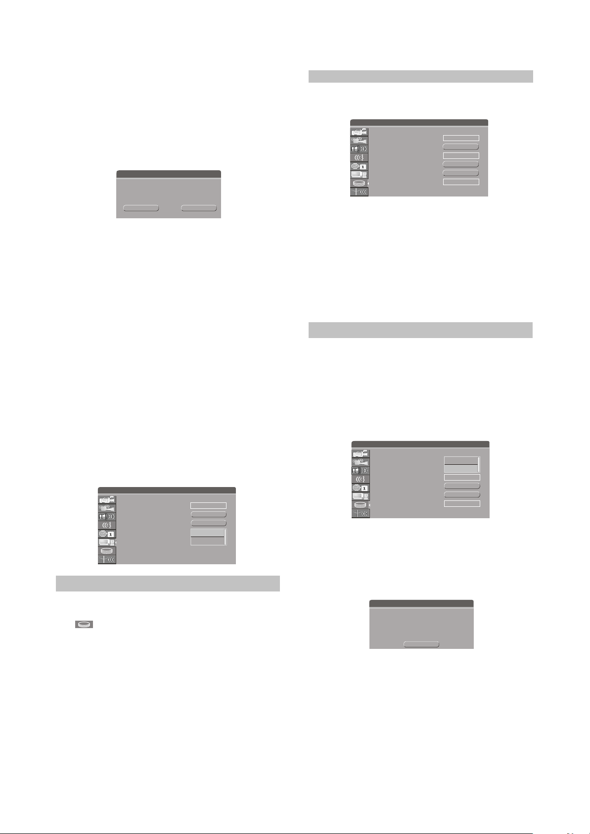
2.4.7 Preferences Setup
1.Display the system setup control menu.
2.Move the cursor by[5],[6] buttons to select
" " item.
3.Press [Select] button to enter the preferences
setup mode.
SETUP MENU-PREFERENCES
Parental Level
Change Password
restore factory settings
Screen saver
Parental Level
By setting this unit s authorization rating
and password, some discs with control grade
cannot be played without inputting the password.
In this way, you can confine the children to watch
the disc unsuitable to them.
1.Select '"Parental Level", and press [Select]
button to display the pop-up list which is
shown as the right figure.
NO PARENTAL
OK
OK
ON
2.Select the rating level by [5],[6] buttons and
press [Select] button to confirm. Then the TV
screen display:
Enter Password
Enter password here.
OK Cancel
3.Input the password and press [Select] button.
Highlight
"OK" by cursor buttons and then
press [Select] button. If the password is right,
the TV Screen return the preferences menu.
Change Password
1.If you want to change the original password,
highlight the
"Change Password" in the menu
through cursor buttons and then press [Select]
button.
2.Select
"Enter password here" by the cursor
buttons and input the original password by
number buttons.
3.Select
"Input new password" by the cursor
buttons and input the new password by
number buttons.
4.Select
"Input new again" by the cursor buttons
and input this password again by number
button.
#This input password in the
"Input new
password" must accord with that in the "Input
new again".
5.Highlight
"OK" by cursor buttons and then
press [Select] button.
#After setting the rating level, when playing the
disc with the rating level higher than what you
have set, you must input the password.
#If you forget the password, you may input the
super password (3308).
New Password
Enter password here.
Input new password.
Input new again.
OK
Cancel
Restore Factory Settings
1.Select
buttons i
"Restore factory setting " by [5],[6]
n the Preferences setup menu, then
press [Select] button, and the TV screen
displays:
- 12 -
Page 18
2.Highlight
"OK " in the menu by [3],[4] buttons.
3.Press [Select] button to make all setup items
restore the factory settings.
#When your unit is in abnormal working mode, it
is probably caused by your wrong setup.
Please try the
operation to make it work normally.
"Restore Factory Settings"
restore factory settings
System will reset all setup items to
the default values. OK to confirm,
Cancel to exit.
OK Cancel
Screen saver
The screen saver function is that an
interesting screen saver picture appears on the
screen automatically, when this unit's video
output signal has no change (that is the
image on the TV screen has no change) for a
certain time.
1.In the Preferences Menu, move the cursor to
select item "Screen saver" by [5], [6] buttons.
2.Press [Select] button , then a pop-up list will be
displayed , which is shown as the right figure.
3.Move the cursor up or down to select "ON" or
"OFF" by[5],[6] buttons.
4.Press [Select] button to turn on or turn off the
screen save function.
#Pressing any button can exit the screen save
mode after the screen saver picture appears.
#The screen saver function is invalid when
playing MP3 and CD-DA Disc.
SETUP MENU-PREFERENCES
Parental Level
Change Password
restore factory settings
Screen saver
NO PARENTAL
OK
OK
ON
ON
OFF
2.4.8 Time Shift Setup
1.Display the system setup control menu.
2.Move the cursor by[5],[6] buttons to select
" " item.
3.Press [Select] button or [4] button to enter the
time shift setup mode.
When the unit is turn on or you press [TimeShift] button from other menus, the last TV
channel viewed will be tuned in and Time shifting
starts automatically. Time shifting allows
"Pausing" the live TV broadcast for up to 360
minutes. At any time, the viewing can resume.
Press [Pause/Step] to pause the broadcast,
press [Play] to resume TV viewing.
NOTE
#If the system is paused for 360 minutes, it will
automatically resume TV viewing.
SETUP MENU-TimeShift
Time shift buffer mode:
Hard disk Info
Space Management:
Empty hard disk
Erase optical disc
TimeShift buffer length
Preserve
Show
Automatica
Go!
OK
180 minutes
Time shift buffer mode:
You can refresh or preserve the Time
shifting buffer data when changing channels by
setting the item.
1.Press the [5],[6] to select the
"Time shift buffer
mode" and the pop-up list will display as the
right figure.
2.Move the cursor to select buffer mode by [5],[6]
buttons and press [Select] button to confirm.
NOTE
#If you set refresh, and change channels or
change source, the time shifting buffer data
will be lost. No message
will be provided prior to doing so.
#If you set preserve, and change channels or
change source, the time shifting buffer data
will be maintained.
SETUP MENU-TimeShift
Time shift buffer mode:
Hard disk Info
Space Management:
Empty hard disk
Erase optical disc
TimeShift buffer length
Preserve
Refresh
Show
Preserve
Automatica
Go!
OK
180 minutes
Hard disk Info
Showing information on HDD size in Gbyte,
HDD available space in Gbyte and percentage.
#File total space occupies ten percent of the
total space of HDD.
Notice!
Video Total Space: 133504 MB
Video Remained Space: 133488 MB
Reserved TSB Space: 6048 MB
Title number 0
File Total Space: 15615 MB
File Remained Space: 15615 MB
OK
Space Management:
There are two space management mode.
1.Press the [5],[6] to select the
"Space
management" item and the pop-up list will
display as the right figure.
2.Move the cursor to select buffer mode by
[5],[6] buttons and press [Select] button to
confirm.
- 13 -
Page 19
NOTE
#When the title is selected being dubbed-in
which case, the title shall be kept until
dubbing is over.
#Automatic: When the HDD is full, the system
should overwrite unprotected title in FIFO
scheme.
#Manual: When the HDD is full, pop up message
"The hard disc drive is full, Please erase some
programs to allow further recording".
SETUP MENU-TimeShift
Time shift buffer mode:
Hard disk Info
Space Management:
Empty hard disk
Erase optical disc
TimeShift buffer length
Preserve
Show
Automatica
Automatica
Go!
Manually
OK
180 minutes
Empty hard disk
Erase all programs on HDD. A message will
be shown as the right figure.
#During the course of emptying hard disc, power
cannot be off. In case power off, please empty
the hard disc again immediately after power
on.
SETUP MENU-TimeShift
Time shift buffer mode:
Hard disk Info
Space Management:
Empty hard disk
Erase optical disc
TimeShift buffer length
Preserve
Show
Automatica
Go!
OK
180 minutes
60 minutes
180 minutes
360 minutes
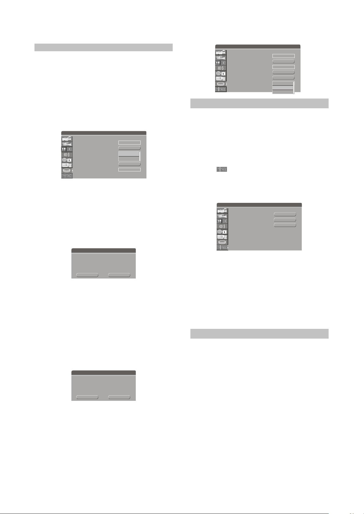
2.4.9 Channel Scan Setup
This unit is equipped with a TV tuner, by
which you can receive TV signals. Before
receiving TV signals, you must proceed tuning
operation. The result of the operation will be
saved and will not be lost after this unit is
switched off.
1.In the System Setup Control Menu, highlight
item " " by [5],[6] button.
2.Press [Select] button, then the System Menu -
Channel Scan menu will appear, as shown in
the right figure.
SETUP MENU-CHANNEL SCAN
Scan channels
Modify channel information
Sort channel order
SCAN
EDIT
SORT
Confirm
All video programs on the hard disk drive
will be lost. Do you want to continue?
OK
CANCEL
Erase optical disc
This operation is only available for
DVD+RW disc. Highlight item "Erase disc" and
press [Select] button, then the system will start
erasing disc contents. This operation will occupy
many time. When erasing, any other operations
can not be proceeded, including standby. Once
the operation starts, it cannot be cancelled
midway. Please do not unplug the unit midway.
Otherwise, the disc will be probably damaged.
Confirm
Warning: This operation will erase all data
on the disc. Are you sure you want to
continue?
OK CANCEL
TimeShift buffer length
1.In the timeshift setup menu, select item
"TimeShift buffer length" by [5/6] button, press
[SELECT] button, then a list menu will appear.
2.Select the desired value by [5/6] buttons, and
then press [SELECT] button to confirm.
#There are 3 timeshift buffer length:60 minutes,
180 minutes,360 minutes.
Scan channels
1.Highlight item "Scan channels", and press
[Select] button to start channel scanning.
#You can press [Stop] button to stop the
scanning during the operation. If do so, the
channel information
#have been obtained during scanning can also
be saved.When scanning a channel, the TV
will show the image of this channel's program.
Note
#Before the channel scan operation, you must
connect the system properly to ensure the TV
signals can enter the system through the "TV
TUNER input" jack. Please refer to "System
connection-System Connection of Recording
External Signals" for the connection
illustration.
Modify Channel Information
Here, you can name the channel after the
corresponding program's name or any other
name you like, sort the channel order to access
the special channel easily, tune the channel
finely and scan the channel manually. You can
manage the channels more easily , and make
this unit receive the TV signal better by these
operations introduced in this section.
- 14 -
Page 20
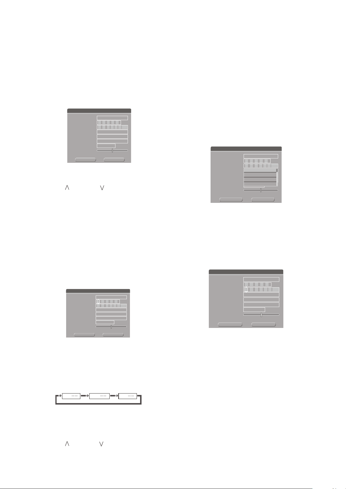
1.Highlight item "Modify Channel Information" in
"Channel Scan" menu, and press [Select]
button, then the "Modify Channel
Information"menu will appear, as shown in the
right figure:
#If this unit has not scanned any programs, the
"Modify channel information" menu can not be
displayed.
Modify channel information
Program Number
Name
Frequency
TV System
NICAM
Audio
Skip
Fine Tuning
OK
P001
- - - - -
1 7 5 . 2 5 MHz
PAL B/G
On
DUAL A
Yes
Cancel
2.Highlight item "Program Number" and select
the desired channel to modify by pressing
[Channel ], [Channel ] button.
3.Change the Channel name: Highlight the
"Name" item, press [Select] button, and then
the right window of the same line will become
input status shown as the following figure.
Move the cursor to a character by [3],[4]
buttons, and then change the character by [5],
[6] buttons. When finishing changing all the
characters, press [Select] button to confirm.
#The changing sequence of the character when
pressing [5] button is as right figure:
#When pressing [6] button the sequence is
reverse.
Modify channel information
Program Number
Name
Frequency
TV System
NICAM
Audio
Skip
Fine Tuning
OK
P001
- - - - -
1 7 5 . 2 5 MHz
PAL B/G
On
DUAL A
Yes
Cancel
4.Change TV System: You can change the sound
mode by item .
#The value of the Standard must match the
"TV System"
received TV signal. If it is not right, the system
will not receive the program's sound signal. So
you should select the right value.
0,1,2, 9 A,B,C, Z
a,b,c, z
5.Change the Search Type: You can change the
search Type. There are two search modes,
frequency and channel.
a. Select a channel number by pressing
[Channel ],[Channel ] buttons.
. According to the demands of the local TV
b
system, set item "TV system"by the methods
described in step 4).
c. Highlight "Frequency" item in the "Modify
channel Information" menu by [5],[6] buttons,
and press [3], [4] button, then the system start
scanning channels.
#If you press [4] button, the system shall scan
channels forward from the current frequency.
#If you press [3] button, the system shall scan
channels backward from the current frequency.
#When encountering a channel with TV program,
the scanning will stop.
Modify channel information
Program Number
Name
Frequency
TV System
NICAM
Audio
Skip
Fine Tuning
OK
P001
- - - - -
1 7 5 . 2 5 MHz
PAL B/G
PAL B/G
PAL D/K
On
PAL l
DUAL A
SECAM L
Yes
Cancel
6.Skip a channel: Highlight the item "Skip", and
press [Select] button to display the drop down
list.Select "YES" or "NO", and then press
[Select] button to confirm.
#If you select
"YES", and when receiving TV
programs, this channel can not be received,
as if it does not exist.
Modify channel information
Program Number
Name
Frequency
TV System
NICAM
Audio
Skip
Fine Tuning
OK
P001
- - - - -
1 7 5 . 2 5 MHz
PAL B/G
On
DUAL A
Yes
Cancel
Frenquencency mode
7.Channel Fine Tuning: Highlight item "Fine
Tune" in the "modify channel information"
menu. Then you can start fine tuning the
channel.
#After finishing the channel scanning, maybe
some channels' frequency is not adjusted to
right value. In this way, when watching these
channels, the image and sound will be misty.
Then you should perform channel fine tuning
to right adjust these channels' frequency.
#Pressing [3] button once can decrease the
frequency.
#Pressing [4] button once can increase the
frequency.
- 15 -
Page 21

#When changing the frequency, the definition of
the image or sound will be changed
correspondingly, then from this, you can know
the effect of the fine tuning.
8.Close/Open NICAM functions: Highlight the
item "NICAM", and press [Select] button to
display the drop down list. Select "ON" or
"OFF" from the list, and then press [Select]
button to confirm.
#The so-called NICAM function include stereo
function and dual dubbings function. When
item "NICAM" is "ON", if the received TV
program supports stereo function, this unit
will output the stereo dubbing; on the other
hand, if the received TV program supports
dual dubbings function, you can select one
of the two dubbings as output by
item"System Setup - Channel Scan - modify
channel information - Audio". Of course, if you
set "NICAM" to "OFF"or receive TV program
without NICAM function, the above functions
are invalid.
9.Switch channel audio language: when the TV
programs received supporting dual dubbings
functions, you can select one of the two
dubbings as output by this item.
a.Highlight item "Audio"in the "modify channel
information" menu, and then press [Select]
button to pop up a submenu list.
b.Select "DUAL A" or "DUAL B " in the list, and
then press [Select] button to confirm.
#You must open the NICAM function first,
otherwise this function will be invalid. Please
refer to the step in section "Modify Channel
Information" to open the NICAM function.
#
The value "DUAL A" or "DUAL B"stands for
one of the two dubbings. If the received TV
program can not support dual dubbing
function, the above operations shall not
influence the output dubbing.
#You can also select "DUAL A" or "DUAL B" by
[Audio] button on the remote control.
Modify channel information
Program Number
Name
Frequency
TV System
NICAM
Audio
Skip
Fine Tuning
OK
P001
- - - - -
1 7 5 . 2 5 MHz
PAL B/G
On
DUAL A
DUAL A
DUAL B
Yes
Cancel
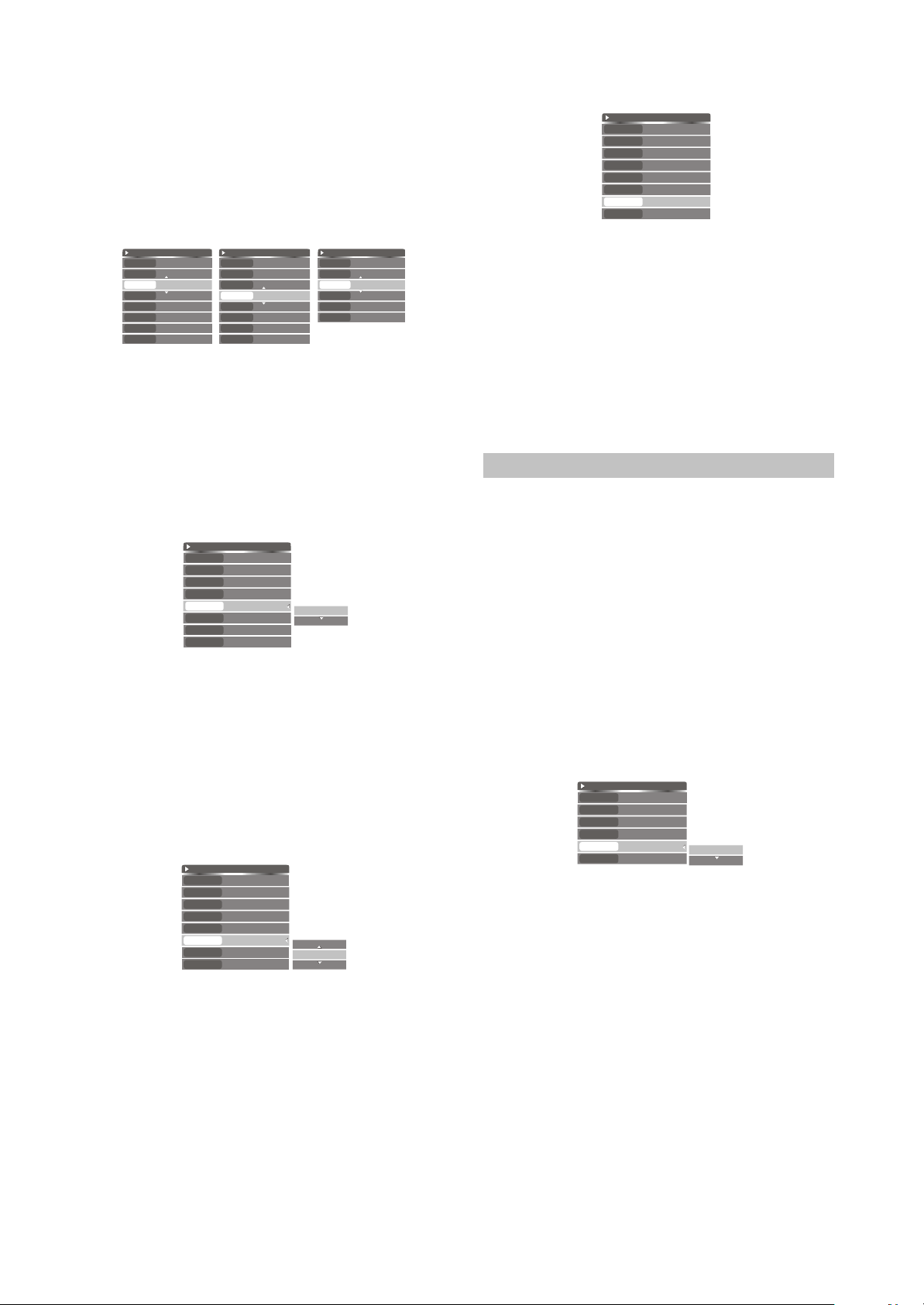
Sort Channel Order
1.Highlight item "Sort channel order",and press
[Select] button.
then a corresponding menu will appear, as
shown in the right figure.
#If this unit has not scanned any programs, the
" "menu can not be
Sort channel order
displayed.
2.Highlight the desired channel in the left list
window by cursor buttons, and press [4]
button, then the channel name will appear in
the right list window, shown as the right figure.
3.Move the channel name up and down by [5],[6]
button to select the right position where you
want to insert this channel.
4.Press [3] button to insert the channel name to
the selected position in the left list window, as
shown in the right figure.
5.Press [Return] button to return to the previous
menu and proceed other settings.
SORT
OK
CANCEL
P001 zg002
P002 Ch027
P003 5-003
P004----------
P005----------
P006----------
P007----------
P008----------
P001 zg002
Note
#When you exit the modify channel information,
the system will ask you whether you want to
save the setting or not.
2.5 PLAYBACK MODE
The unit has two playback mode, DVD/VCD
playback and HDD playback.
2.5.1 DVD/VCD/CD Playback
Entering the Playback Mode
In the playback mode, this unit is totally the
same as a high quality DVD player. The way to
enter the playback mode is as following:
1.Connect this unit with the TV set (Refer to
"System Connection" for details), turn on the
TV set and switch it to the AV input mode.
2.Plug in the unit, then press [Standby / On]
button to turn it on.
3.Press [Open / Close] button to open the disc
tray.
4.Load the disc correctly as shown in the
illustration.
#When loading a disc, the smooth side should
face down and the side with silk-screen should
face up.
5.Press [Open / Close] button to close the disc
tray, then the system starts playing.
- 16 -
Page 22

#According to different discs, the system will
probably enter the Title Selecting Playback
mode or Menu Playback mode. If such
condition appears, the disc will not be
continued playing(please refer to the following
text).
6.If system is in other working mode, please
press [DVD] button to enter the playback
mode.
7.If you press [Play] button, the TV screen
displays " " . Please exit current working
and then press [Play] button again.
#When writing or erasing, pressing [Play] button
will be invalid.
#If there is no disc in the loader or load the disc
that this unit doesn't support or has been
damaged badly, pressing [Play] button will be
invalid.
Playback from the Menu Displayed
1.When playing a DVD disc, it will enter menu
playing mode. The menus of different discs
are different. In general, you can select the
playing language, set the subtitle language
and so on by that menu. To perform some
operations , you only need to highlight the
corresponding item by cursor buttons and
confirm by [Select] button.
2.When playing some VCD disc, these menus
will be a list of tracks. You can select a track
by number or cursor buttons, then press
[Select] button to play the selected track.
3.During playing, you can open the disc menu
by pressing [Menu] button. Of course, all the
functions about the disc menu can be fulfilled
by the corresponding control menu based on
this unit.
1
3
2
4
Playback from the Titles Displayed
This operation is only available for the DVD
disc. During playing, if you want to select some
title to play, you can press [Title] button.
Then the screen will display the title icons list,
shown as the right figure. You can highlight an
icon you like, then press [Select] button to play
it.
Notes
#The title menu of different DVD discs may be
different.
#Not all DVD discs have title menu. For some
DVD discs without title menu, pressing [Title]
button is invalid.
Ending Playback
1.Press the [Stop] button.
#This unit enters the pre-stop mode.
#In the pre-stop mode, this unit automatically
memorizes the pre-stop point. If you press
[Play] button ,this unit will resume the
playback from the pre-stop point (Playback
starts from the beginning of the prestopped track for MP3). If you press [Stop]
button twice, this unit will enter stop mode
and the memory is cleared.
2.Press [Open/Close] button to eject the tray.
3.Take the disc out.
4.Press [Open/Close] button to retract the disc
tray.
5.Press [Standby/On] button to end the
operation.
Note
#If the disc is badly damaged or loaded
incorrectly, the OSD will display "NO DISC".
Playing Mode Control
1.Press [Info] button twice to open the main
control menu.
DVD
MODE
Normal
4
When playing DVDWhen playing VCD
Trick mode
TITLE
CHAPTER
AUDIO
SUBTITLE
ANGLE
T -TIME
03/06
04/19
01/01-ENG
01/03-ENG
01/01
00:13:02-01:15:17
CDDA
MODE
Normal
4
Trick mode
01/17
TRACK
STEREO
AUDIO
TIME
0:02:41-0:0:55:23
When playing CD
VCD
MODE
Trick mode
TRACK
AUDIO
PBC
TIME
Normal
4
01/15
STEREO
PBC ON
00:01:25-00:02:28
2.Highlight "MODE" item by [5], [6] buttons, and
press [Select],[4] button to display the drop
down list window shown as the right figure.
3.Select one value in the list, then press [Select]
button to confirm.The meanings of the values
are as the following:
DVD
MODE
Normal
4
Trick mode
03/06
TITLE
04/19
CHAPTER
01/01-ENG
AUDIO
01/03-ENG
SUBTITLE
01/01
ANGLE
00:13:02-01:15:17
T -TIME
Main control menu
Normal
A-B REPEAT
CHAPTER REPEAT
Title Repeat
DISC REPEAT
mode value list
- 17 -
Page 23

Normal
1
2
A-B Repeat
3
Chapter Repeat
Sequence Playback
A-B Playback
Segment Repeat
Playback
4
Title Repeat
5
Disc Repeat
6
Program
7
Random
8
Track Repeat
Title Repeat Playback
Disc Repeat Playback
Program Playback
Random Playback
Track Repeat Playback
The list values are different when playing
different discs.For most operations, if you
perform step , things are over, but if you select
"A-B Repeat" and “Program",you shall perform
the following steps.
4.If you select "A-B Repeat", when pressing
[Select] button, the menu becomes the style
shown as the right figure. You need to set the
B point. Press [Select] button to display mode
value list again. Now, please wait, and when
meeting your desired point, you can press
[Select] button to set the B point.
#During your waiting, the main control menu will
disappear. You also can press [Info] button to
hide the menu.
DVD
Set A_
MODE
4
Trick mode
03/06
TITLE
04/19
CHAPTER
01/01-ENG
AUDIO
01/03-ENG
SUBTITLE
ANGLE
T -TIME
01/01
00:13:02-01:15:17
¢Þ
5.If you select “Program” in step , the following
list windows will pop up.
¢Ü
By this menu you can select your favorite
contents from the disc to play in your pointed
sequence.
Edit program play list
TITLE
TITLE 01
¢ÝIf you select "Program" in step ¢Û, the following list
TITLE 02
TITLE 03
windows will pop up.
TITLE 04
TITLE 05
TITLE 06
Favorite/Program
Playing Mode Control(CONTINUED)
You can control the two list windows by the
following points.
#Move the cursor between left window and right
window by [3], [4] buttons.
#Move the cursor up and down in one of the
windows by [5], [6] buttons.
#Highlighting an item in left window, then
pressing [Add/Clear] button can add the item
to right list window.
#Highlighting an item in right window, then
pressing [Add/Clear] button can delete the
item
#If the items of the left window is title, you can
expand item by pressing [Select] button,
shown as the following figure:
TITLE
TITLE 01
TITLE 02
TITLE 03
TITLE 04
TITLE 05
TITLE 06
TITLE 07
TITLE 08
TITLE 09
TITLE 10
Press the [Select] button
Press the [Select] button
Unfold the content of "TITLE 01"
Go back to the previous window
CHAPTER OF TITLE 01
CHAPTER 01
CHAPTER 02
CHAPTER 03
CHAPTER 04
CHAPTER 05
CHAPTER 06
CHAPTER 07
CHAPTER 08
CHAPTER 09
6.Add your favourite contents to right window in
your desired sequence according to the above
description, then move the cursor to the right
window and press [Select] button to start
program playback.
Playback Process Control
1
playback
2
Stop
3
Pause
4
>>2~32 fast playback, the number shows the
speed of the playback
5
<<2~32 fast backward playback, the number
shows the speed of the Backward
playback
>>1/2~1/8 or <<1/2~1/8 slow playback, the
6
fraction shows the
Degree of slow
Playback
#The list values are different when playing
different disc.
DVD
MODE
Normal
4
Trick mode
TITLE
CHAPTER
AUDIO
SUBTITLE
ANGLE
T -TIME
03/06
04/19
01/01-ENG
01/03-ENG
01/01
00:13:02-01:15:17
4
<
;
>>2
>>4
Title / Chapter / Track Selection
1.Press [Info] button twice to open the main
control menu.
2.Highlight "Title"/"Chapter"/"Track" (for VCD/
SVCD) item,and press [Select] button to make
it in input mode.
- 18 -
Page 24
3.Enter your desired number by number buttons,
and press [Select] button, then the system
will start playing the selected Title/ Chapter/
Track.
#The left part of the item value is the number of
current playing number.
DVD
MODE
Normal
4
Trick mode
03/06
TITLE
04/19
CHAPTER
01/01-ENG
AUDIO
01/03-ENG
SUBTITLE
ANGLE
01/01
T -TIME
00:13:02-01:15:17
Highlight title item
DVD
MODE
Normal
4
Trick mode
03/06
TITLE
04/19
CHAPTER
01/01-ENG
AUDIO
01/03-ENG
SUBTITLE
ANGLE
01/01
T -TIME
00:13:02-01:15:17
Highlight chapter item
VCD
MODE
Normal
4
Trick mode
01/15
TRACK
STEREO
AUDIO
PBC
PBC ON
TIME
00:01:25-00:02:28
Highlight track item
when playing VCD/SVCD.
Audio / Subtitle Selection
1.Press [Info] button twice to open the main
control menu.
2.Highlight "AUDIO"/"SUBTITLE" item by [5], [6]
buttons,then press [Select]/[4] button to open
the drop down list shown as the right figure.
3.Select one value in the list, and then press
[Select] button to confirm.
DVD
MODE
Normal
4
Trick mode
03/06
TITLE
04/19
CHAPTER
01/01-ENG
AUDIO
SUBTITLE
01/03-ENG
ANGLE
01/01
T -TIME
00:13:02-01:15:17
Highlight "AUDIO" item
1.CHI DOLBY
2.ENG DTS
#The values of the lists are based on the played
disc
#For DVD disc, the values of audio list will be
DOLBY, DTS and so
For VCD/SVCD, the values of audio list will be
#
on.
STEREO, LEFT and RIGHT.
#The settings of these items also can be done in
DVD menus.The initial value of the two items
can be set in System Setup.
DVD
MODE
Normal
4
Trick mode
03/06
TITLE
04/19
CHAPTER
01/01-ENG
AUDIO
SUBTITLE
01/03-ENG
ANGLE
01/01
T -TIME
00:13:02-01:15:17
Highlight "SUBTITLE" item
0.OFF
1.CHI
2.ENG
Angle Selection
1.Press [Info] button twice to open the main
control menu.
2.Highlight "ANGLE" item by [5], [6] buttons, and
press [Select] button to make it in input mode.
#The right side of the numbers beside the icon is
the total angle number Of this disc ; the left is
the current angle number.
3.Input the ANGLE number you need by number
buttons, and press [Select] button to confirm.
DVD
MODE
Normal
4
Trick mode
03/06
TITLE
04/19
CHAPTER
01/01-ENG
AUDIO
01/03-ENG
SUBTITLE
01/01
ANGLE
00:13:02-01:15:17
T -TIME
PBC ON/OFF
1.Press [Info] button twice to display the main
control menu.
2.Highlight "PBC" item by [5], [6] buttons, and
then press [Select]/[4] button to display the
drop down list window shown as the right
figure.
3.Select "ON" or "OFF" from the list, and then
press [Select] button.
4.Pressing [Menu] button also can make the
PBC on or off.
Notes
#The PBC function refers to the menu playback
function of the VCD 2.0 disc. When the PBC is
on, the TV screen displays a list of all the
tracks. You can select any track by number
buttons on the remote control, and press
[Select] button to play from the selected track.
During the playing, if you want to play the
other track , you need to press [Menu] button
to display the track list, and select another
track by number buttons then press [Select]
button to confirm. When the PBC is off, the
system plays the disc contents in sequence.
Not all the VCD discs can proceed PBC
playback.
VCD
MODE
Normal
4
Trick mode
01/15
TRACK
STEREO
AUDIO
PBC ON
PBC
TIME
00:01:25-00:02:28
PBC ON
PBC OFF
T-Time/Time Display
You can select a point to start playing.
1.Press [Info] button twice to display the main
control menu.
2.Highlight "T-Time" (For DVD) or "Time"(For
VCD/SVCD) item by [5], [6] buttons, and then
press [Select] button to open the drop down
list shown as the right figure.
3.Select you desired item by [5], [6] buttons, then
press [Select] button to confirm.
#In DVD+R or DVD+RW playing mode, it only
display "TITLE" time.
#In normal DVD playing mode, it includes
"TITLE" and "CHAPTER", in VCD/SVCD
playing mode, it includes "DISC" and "TRACK".
- 19 -
Page 25
#The left part of the item values is the elapsed
time of the title/track, the right one is the
remain time.
DVD
MODE
Normal
Trick mode
4
TITLE
03/06
CHAPTER
04/19
AUDIO
01/01-ENG
SUBTITLE
01/03-ENG
ANGLE
T -TIME
01/01
00:13:02-01:15:17
TITLE
CHAPTER
The Operations of Function Buttons
Most of the operations in playing mode can
be done by menu or function buttons, some
operations only can be done by menu, and other
operations only can be done by function buttons.
1.Repeat 1/all button---Repeat playback
Press [Repeat 1/all] button repeatedly, and the
playing mode will be circularly switched in the
following sequence:
Normal
Chapter Repeat
Title Repeat
Disc Repeat
2.Repeat A-B button---Repeat playback
Press [Repeat A-B] button repeatedly, and
the playing mode will be circularly switched in
the following sequence:
Normal A-B Repeat
Set A_
3.FWD button---Forward playback
Press [8] button repeatedly, and the playing
speed will be changed in the following sequence:
Normal Speed Playback
>>2
>>4
......
>>32
4.REW button---backward playback
Press [7] button repeatedly, and the
backward playing speed will be changed in the
following sequence:
Normal Speed Playback
<<2
<<4
......
<<32
5.SKIP button
A.If you press the [:] button on the remote control,
the system goes forward into the next chapter
(to DVD) or track (to VCD/SVCD) and begins
playback.
b.If you press the [9] button on the remote
control, the system goes backward into the
previous chapter (to DVD) or track (to VCD/
SVCD) and begins playback.
6.Pause/Step button---Pause playback & playing
frame by frame.
a.When playing the valid disc , if you press
[Pause/Step] button, the playback will pause.
b.If you press [Pause/Step] button again, the
picture goes forward a frame.
C.If you press [Play] button, the system will
enter normal playback.
7.Vol+/Vol-/Mute button---Volume control
a.If you press [Mute] button, the system has or
hasn't audio output.
b.If you press the [Vol+] button, the volume
increases.
c.If you press the [Vol-] button, the volume
decreases.
8.Goto button---Switching the mode of selection
playing
a.In the playback mode, you can press [Goto]
button to highlight different select item
circularly in the playback control menu. You
can input the corresponding values by using
the remote control with the method aforesaid.
#The illustration below is the example of playing
the DVD disc. It is similar to other discs.
TITLE: - -
Title Selection
CHAPTER: - -
Chapter Selection
01/04 11/27
TIME: - : - -: --
Time Selection
#Pressing [Goto] button is invalid to some discs.
b.When play disc (as JPEG/MP3/DivX disc)
with directory structure, you must press [Goto]
button to confirm instead of pressing [Select]
button.
#In directory structure, to go to corresponding
directory, you need press [Goto] button once
and input the number of the directory then
press [Goto] button again to confirm. Press
[Select] button to open it.
#In file structure, press [Goto] button and input
the number you desired, then press [Goto]
button to go to corresponding file and start
playing it.
#In playing MP3/DivX file, to go to some time
position of current file and start playing, at first
press [Goto] button twice, and input the
number your desired, then press [Goto] button
again to confirm.
PIP
When playing DVD, VCD, HDD video and
TimeShift content, press [PIP] button and TV
program can be played at the same time.
- 20 -
Page 26
¢Ù
¢Ú
¢Ù
¢Ú
HDD
No. CH Date Time Title
001
S-017
11/30/99 00:04 Title 1
002
003
004
Ch002
S-002
S-002
11/30/99
11/30/99
11/30/99
00:00
00:01
00:07
Title 2
Title 3
Title 4
00:03:21
SP PAL
¢
¡
£
¤
For other options Press DVD, Time-
Shift, DV, FILE, SETUP or TIMER
keys
Press key to
select program(s)
Press key to copy
selected program(s) to
DVD
Press key to sort
programs by name,
date or time
Add/Clear
Dub
Sort
"Recording to HDD".
Copy
Delete
Rename
Move
Create Dir
Select all
UnSelect all
Favorite
Favorite list
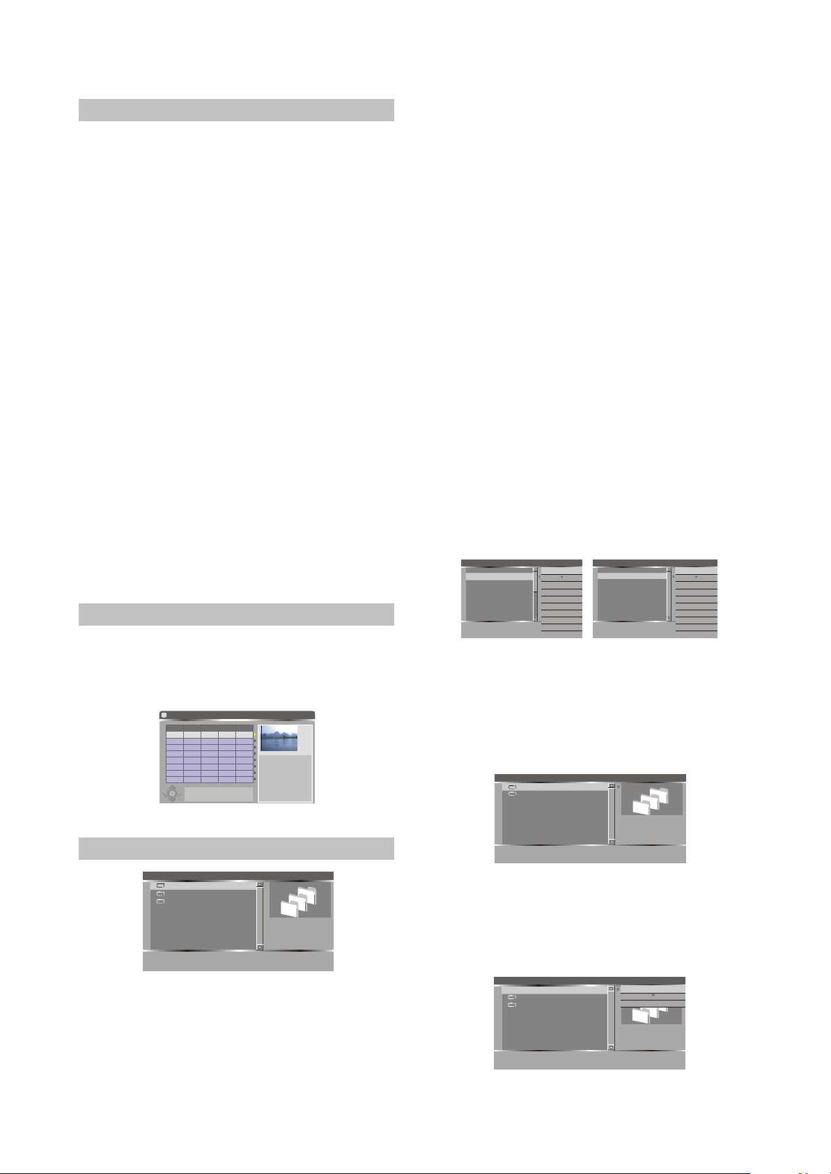
File Manager AUDIO < 00:00:00 - 00:00:00
Prepare to copy selected file(s) to
another directory.
Copy
Select all
UnSelect all
Favorite
Favorite list
Delete
Rename
Move
Create Dir
../
2¯ 02.MP3
3¯ 03.MP3
4¯ 04.MP3
5¯ 05.MP3
6¯ 06.MP3
7¯ 07.MP3
8¯ 08.MP3
1¯ 01.MP3
Files onto unrecordable disc and USB
Copy
Delete
Rename
Move
Create Dir
Select all
UnSelect all
Favorite
Favorite list
File Manager AUDIO < 00:00:00 - 00:00:00
Prepare to copy selected file(s) to
another directory.
Copy
Select all
UnSelect all
Favorite
Favorite list
Delete
Rename
Move
Create Dir
../
2¯ 02.MP3
3¯ 03.MP3
4¯ 04.MP3
5¯ 05.MP3
6¯ 06.MP3
7¯ 07.MP3
8¯ 08.MP3
1¯ 01.MP3
Files onto unrecordable disc and USB
Right
Operation menu
Left
Return to file manager.
1 HDD DRIVER
2 DVD DRIVER
Copy
Select all
UnSelect all
Favorite
Favorite list
Delete
Rename
Move
Create Dir
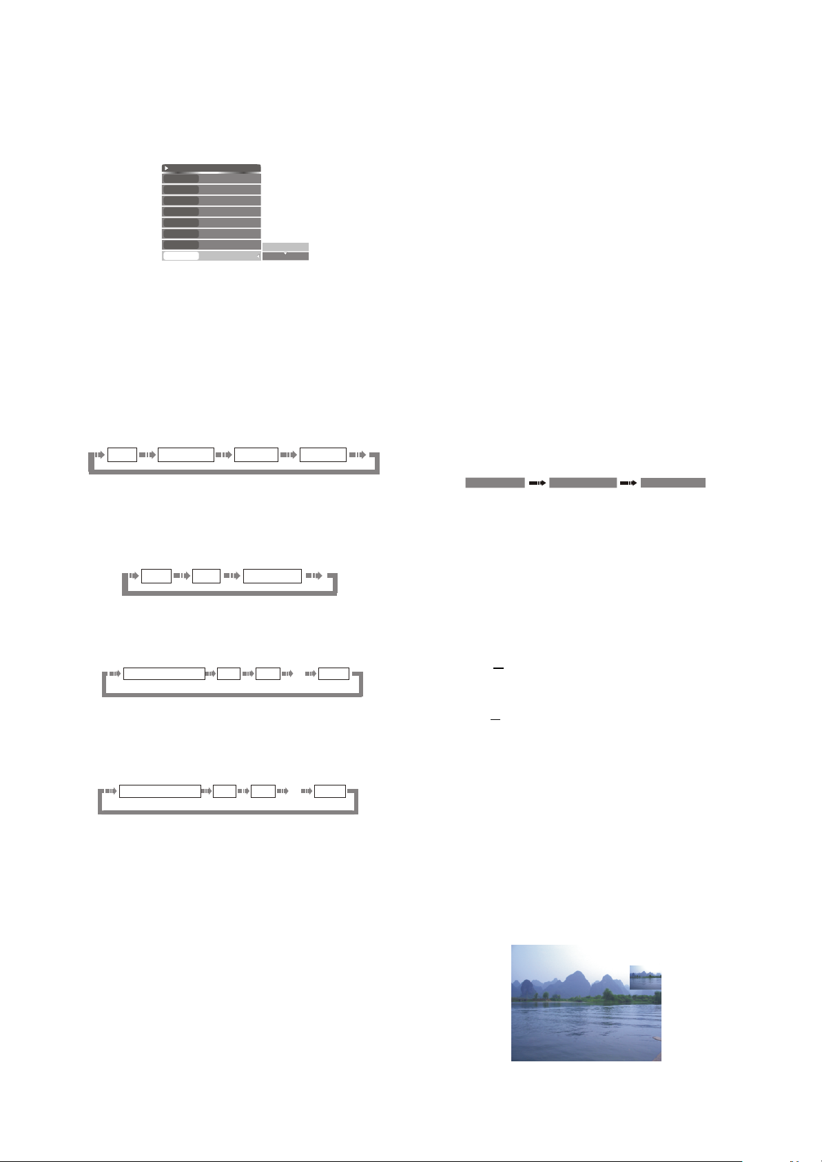
2.5.2 HDD Playback
The unit contains Hard Disc. You can
playback programs from HDD like playback from
optical drive. The way to enter the playback from
HDD mode is as following:
1. Make sure there are programs which have
been saved on the HDD.
The operations about how to save programs
on the HDD please refer to
"Recording to HDD".
2. Press [HDD] button switch to HDD mode.
The title list presents the list of all the
programs you have saved on the HDD.
3. Playback from HDD
Once you have highlighted the program on
the list, select the programs which you want to
playback by [5],[6] button and then press [Select]
button to play. You select the program which you
want to playback by [5],[6] button, and press
right key, will pop up a sub menu, select the
""
play item by [5],[6] button, and press [Select]
button to play.During HDD playback, you can
control the system output by using the following
remote control key (REW, FWD, PREV, NEXT,
Slow, Mute, Vol+/-)
4.Return to menu
Press [HDD] button will return to the menu
list.
¢Ù
Notes
#In play mode, if you press left cursor button, it
¢Ú
will turn back 10 seconds, press right cursor
#button, it will turn forward 30 seconds.
Press [Play] button is invalid.
HDD
No. CH Date Time Title
11/30/99 00:04 Title 1
S-017
001
11/30/99
00:00
2.6 FILE OPERATION MODE
002
003
004
£
¢
¡
¤
Ch002
S-002
S-002
For other options Press DVD, TimeShift, DV, FILE, SETUP or TIMER
keys
¢Ù
11/30/99
11/30/99
Title 2
00:01
Title 3
00:07
Title 4
Add/Clear
Press key to
select program(s)
Dub
Press key to copy
selected program(s) to
DVD
Sort
Press key to sort
programs by name,
date or time
00:03:21
SP PAL
2.6.1 File Copy Menu
1 HDD
2 Disc
3 USB1
SELECT
¢Ú
Enter sub-level
RECORD
File Size: N/A
Modify Date:
D/A
Show favorite list
File Manager AUDIO < 00:00:00 - 00:00:00
When this player is working normally, press
[FILE] button to enter file playback mode, and TV
screen will display the list shown as in the right
figure.In this mode, you may play and copy files
with directory structure onto HDD.
optical drive and USB device.Under File
Manager root directory, press [5/6] button to
select your desired directory, and then press
[SELECT] button to enter the subdirectory.
1. Higlight you desired file or directory by [5/6]
buttons, and then press [SELECT] button.
#If the highlight item is file, the system will start
playing it.
#If the highlight item is directory, the system will
expand its contents.
#To return to previous menu, please press [3]
button.
2. Press [Add/Clear] button to mark the file or
directory of the position where the cursor is
(multiple files and directories may be marked)
or cancel the mark.
#Return to the previous directory or enter the
next directory, and mark will disappear
automatically.
3. Press [4] button and the pulldown menu will
pop up, shown as the follow figure.
#When disc is not recordable, the function of
Delete, Rename and Create Dir in the menu
cannot be realized.
File Manager AUDIO < 00:00:00 - 00:00:00
../
1¯ 01.MP3
a
2¯ 02.MP3
a
3¯ 03.MP3
a
4¯ 04.MP3
a
5¯ 05.MP3
a
6¯ 06.MP3
a
7¯ 07.MP3
8¯ 08.MP3
Add current file to favorite list.
Files onto HDD and recordable disc
Copy
Delete
Rename
Move
Create Dir
Select all
UnSelect all
Favorite
Favorite list
File Manager AUDIO < 00:00:00 - 00:00:00
../
1¯ 01.MP3
2¯ 02.MP3
3¯ 03.MP3
4¯ 04.MP3
5¯ 05.MP3
6¯ 06.MP3
7¯ 07.MP3
8¯ 08.MP3
Prepare to copy selected file(s) to
another directory.
Files onto unrecordable disc and USB
Copy
Delete
Rename
Move
Create Dir
Select all
UnSelect all
Favorite
Favorite list
1.Copy
After well marking the file or directory that
you wish to copy, this function will help to copy
these files. If file is not marked, it will copy the
file where the cursor is. Press [SELECT] button
to enter the directory shown as in the right figure.
Copy To... AUDIO < 00:00:00 - 00:00:00
1 HDD DRIVER
2 DVD DRIVER
Right
Operation menu
Left
Return to file manager.
Under this directory, you may select to copy
file to HDD, DVD+RW disc and unfinalized
DVD+R disc. Press [SELECT] button to enter
target disc, and then press [4] button to pop up
the list shown as in the right figure.
File Manager AUDIO < 00:00:00 - 00:00:00
../
1 CD01/
2 CD2/
3 ¯ TRACK01.MP3
Copy selected file(s) to current
directory.
Do Copy
Rename
Create Dir
File Size: N/A
Modify Date:
D/A
- 21 -
Page 27
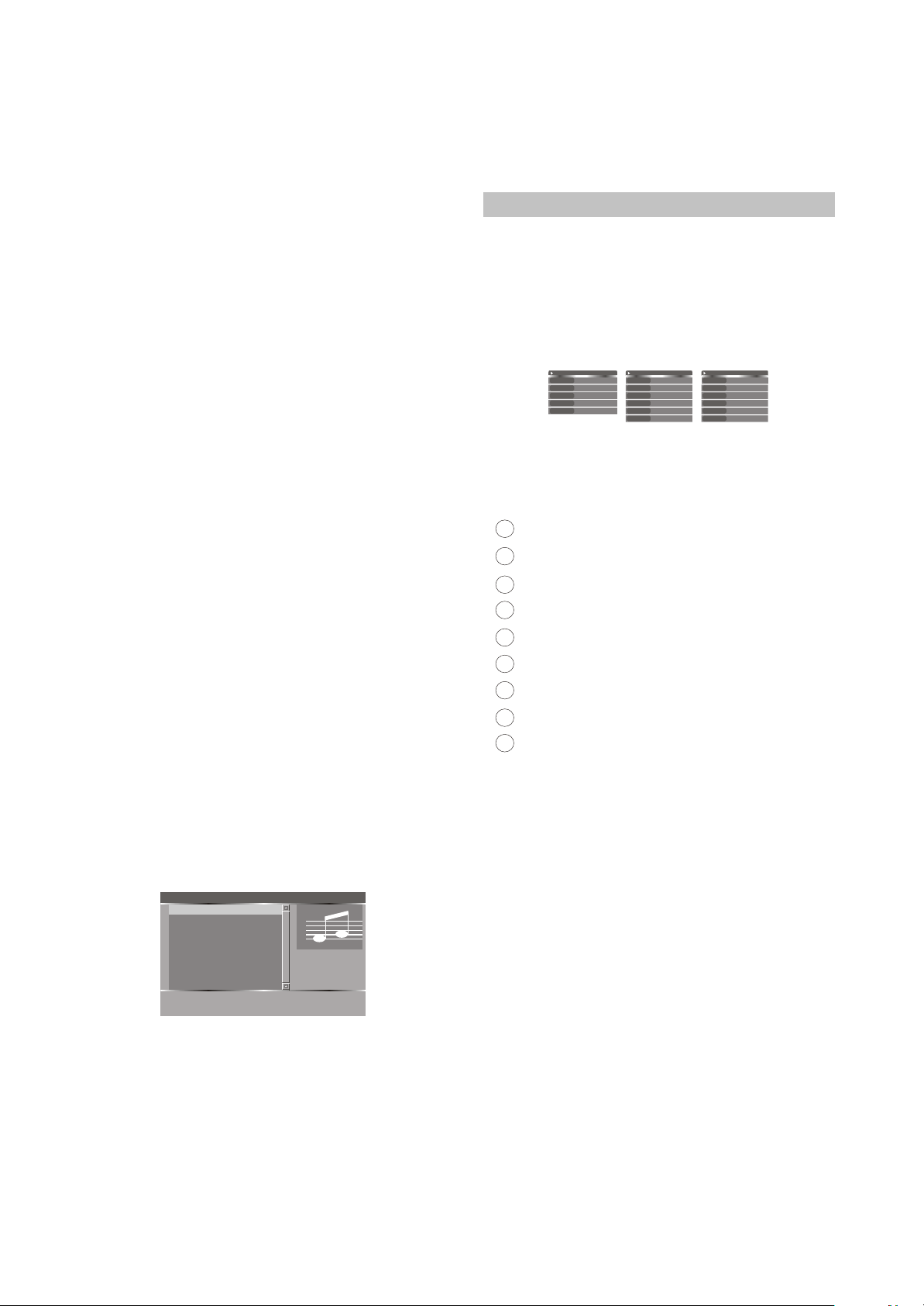
Do Copy: Begin to copy the marked file to
the current directory.
Rename: Change name of the file or
directory where the cursor is.
Create Dir: Create a new subdirectory
under the current directory.
#After file copy finishes, return to source
directory. If you want to check the copied file,
enter the target directory of the copied file.
2.Delete
Delete the current file or directory.
3.Rename
Change name of the file or directory where
the cursor is.
4.Move
This function will move file to other directory
on HDD, DVD+RW disc and DVD+R disc not
finalized.
5.Create Dir
Create a new subdirectory under the
current directory.
6.Select all
Mark all files and directory under the current
directory.
7.Unselect all
Cancel all marked files under the current
directory.
8.Favorite
Place the marked file under the current
directory into your favorite list.
9.Favorite list
This function may help you to enter your
favorite list, or press [RECORD] button to enter
the list. The favorite list is divided into 3 file
folders of audio, video and picture, and you may
use [RECORD] button to fulfill the switch in
folders.
Audio Favorite List AUDIO < 00:00:00 - 00:00:00
1. 06.MP3
2. 05.MP3
3. 04.MP3
4. 03.MP3
5. 02.MP3
6. 01.MP3
Left
Return to file manager.
Record
Switch A/V/P favorite li
SELECT
Add/Clear
File Size: 3MB
Modify Date:
04/18/2006
Play hilighted file
Unfavorite current file.
#In this process, press [3]button to return to the
previous directory.
#When playing files, press [4] button and Invalid
will display.
#That copy file to USB device is not supportable.
#The disc that has copied file cannot be used to
record external signal source. If you want to
record external signal.
Please enter Timeshift state, In SETUP menu
---TimeShift --- Erase optical disc item erase
"
"
disc. The disc that has recorded external
signal cannot copy files until disc erasing.
2.6.2 Playback Control Menu
Loading a disc with directory structure or
playing a file like JPEG/MP3//DivX, your can
display the playback control menu by pressing
[Info] button once or twice. You can do some
operation to current file by the playback control
menu. The playback control menu will be
different when playing different type disc.
AUDIO
TYPE
AUDIO
MODE
Normal
4
TRICK
AUDIO
STEREO
TIME
0:02:41-0:0:55:23
When playing MP3
PIC
TYPE
PIC
MODE
NORMAL
4
TRICK
Normal
WIPE
FITSCREEN
ZOOM
ROTATE
CLOCKWISE 0
When playing JPEG
VIDEO
VIDEO
TYPE
MODE
Normal
4
TRICK
STEREO
AUDIO
TIME
0:00:00 / 0:00:00
LANG
LANGUAGE 1
When playing DivX
The means of the list values are as
following:
1.Type: display current playback type
2.MODE:
1
AUDIO ¡ª playing MP3
Normal
2
Track Repeat
3
Folder Repeat
4
A-B Repeat
5
Disc Repeat
6
Random
7
Folder Random
Disc Random
8
9
Intro Play
Sequence Playback
Track Repeat Playback
PIC ¡ª playing JPEG
Folder Repeat Playback
A-B Playback
Disc Repeat Playback
Random Playback
Folder Random Playback
Disc Random Playback
Introduce Playback
3.TRICK: please refer to "File Operation Mode --
- Playback Process Control" for submenu
content
4.AUDIO: you can select different audio channel
output (stereo/left/right),you can also do it by
press [Audio] button repeatedly.
5.TIME: you can select displaying elapsed time
or remain time.
6.WIPE: please refer to "File Operation Mode ---
Control Wipe Mode when Playing JPEG Disc".
7.ZOOM: please refer to "File Operation Mode ---
Control Zoom Mode when Playing JPEG
Disc".
8.ROTATE: please refer to "File Operation Mode-
---Picture Rotating when Playing JPEG Disc".
9.LANGUAGE:if the disc include several kinds of
language, you can select desired language
from this item.
Notes
#Some discs labelled with MPEG4 on the market
actually are *.rm/*.ra/*.ram/*.rmm and others.
- 22 -
Page 28
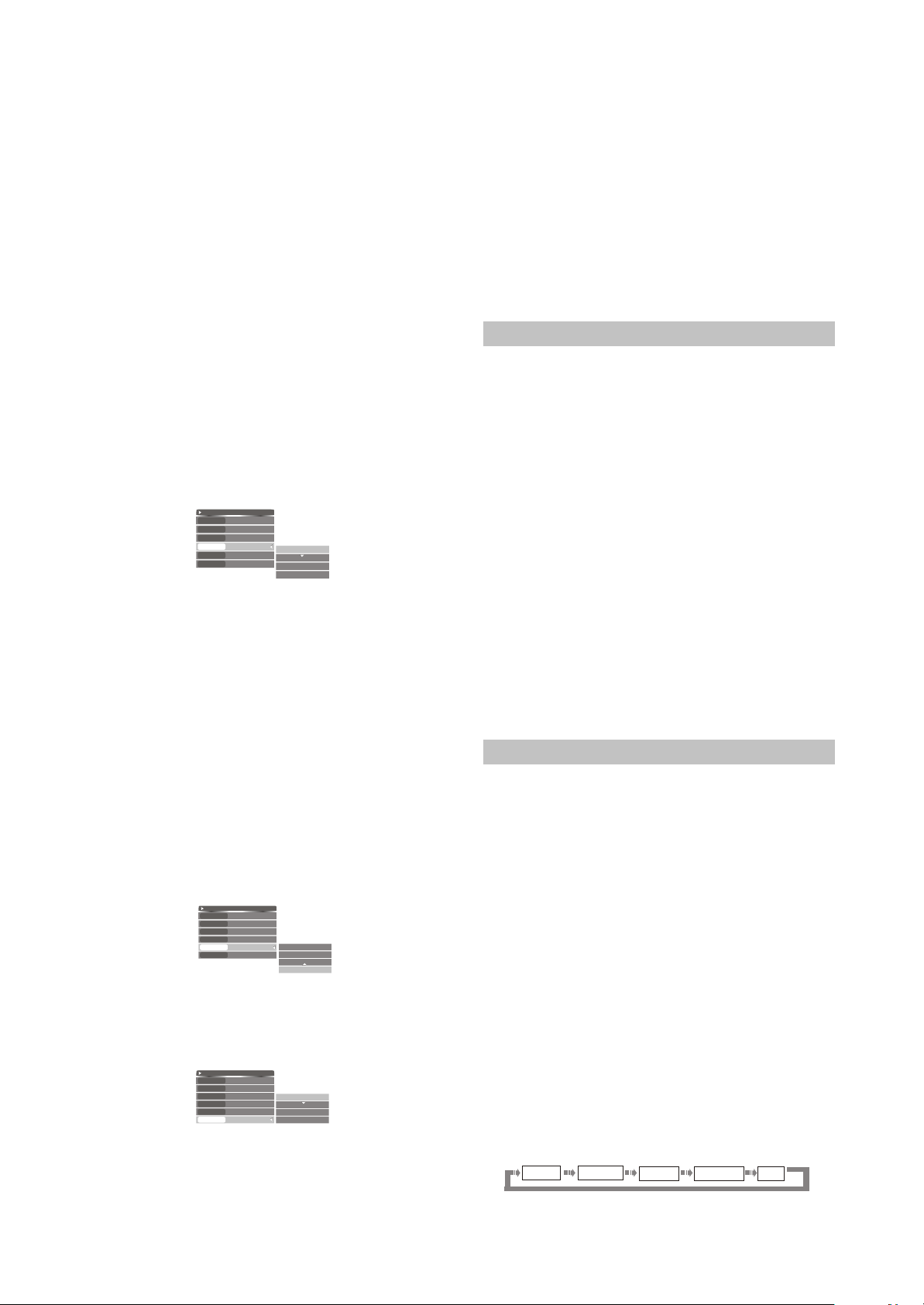
With which are incompatible. Please take care
when buying discs.
Control Wipe Mode when Playing JPEG Disc
In general, many pictures will be saved in
the disc as the JPEG file format. When playing
this disc, the pictures will be shown on the
screen one by one. You can select the mode of
the picture switching.
1.Playing a JPEG file, press [Info ] button twice
to display the playback control menu.
2.In the playback control menu, select the WIPE
item by [5], [6] buttons, and then press [Select]
button to display the wipe mode list shown as
the right figure.
3.Select the desired mode of the picture
switching from the list by [5], [6] buttons and
then press [Select] button.
4.
Press [Info] button to return to the previous
menu.
File Play
TYPE
PIC
MODE
NORMAL
4
TRICK
Normal
WIPE
ZOOM
ROTATE
FITSCREEN
CLOCKWISE 0
Normal
Down
Up
Right
Control Zoom Mode when Playing JPEG Disc
This function can zoom in or zoom out the
picture to facilitate your watching.
Playing a JPEG file, press [Info ] button twice
1.
to display the playback control menu.
2.In the playback control menu, select the ZOOM
item by [5], [6] buttons, and then press [Select]
button to display the zoom mode list shown as
the right figure.
3.Select the percentage of zoom from the list by
[5], [6] buttons, and then press [Select] button.
#The value of "FITSCREEN" means the full
screen display.
Press [Info] button to return to the previous
4.
menu.
File Play
TYPE
PIC
MODE
NORMAL
4
TRICK
Normal
WIPE
ZOOM
ROTATE
FITSCREEN
CLOCKWISE 0
100%
200%
400%
FITSCREEN
Picture Rotating when Playing JPEG Disc
This function can change the angle of the
placement of the picture on the screen to
facilitate your enjoying.
File Play
TYPE
PIC
MODE
NORMAL
4
TRICK
WIPE
ZOOM
ROTATE
Normal
FITSCREEN
CLOCKWISE 0
CLOCKWISE 0
CLOCKWISE 90
CLOCKWISE 180
CLOCKWISE 270
1.Playing a JPEG file, press [Info] button twice
to display the playback control menu.
2.Select the ROTATE item in the playback
Control menu by [5], [6] buttons, and then
press [Select] button to display the rotating
value list shown as the right figure.
#There are four kinds of rotating angles: 0, 90 ,
180 , 270.
3.Select the desired angle from the list by [5], [6]
buttons and then press [Select] button.
Press [Info] button to return to the previous
4.
menu.
2.7 RECORDING MODE
2.7.1 Summarization
This unit has various external input signal
terminals including S-video input, composite
video input, SCART input (CVBS), TV tuner input,
DV input , and stereo audio input. You can record
any group of these video and audio input signals.
The recordable discs of this unit are DVD+RW
and DVD+R. There are four recording qualities to
DVD+R/RW discs with 4.7 GB (12CM single side)
can be selected, including HQ(about 1H),SP
(about 2H), EP(about 4H), SLP(about 6H). This
unit incorporates time recording function with
which you can prepare a record schedule beforehand and it will record your desired programs
according to the schedule on time. With a DV
camera recorder, you can also monitor and
record a certain scene automatically and
intelligently for a long time. You can record
programs on HDD and copy the programs from
HDD to recordable disc.
2.7.2 Viewing the inputted source
After entering the record mode, the source
signal will be shown directly on the TV screen.
By this function you can get a preview of the
external signals for selecting the desired signal
rightly more.
Selecting the signal to view
1.Connect the system (please refer to "System
Connections-System Connection of recording
external signals" for details). Make the source
equipment works properly, and let it output the
signal intended for recording.
2.Press [Source] to select desire source, and
then the TV screen will show the
corresponding picture.
3.Pressing [Source] button can expediently view
the external signals one by one. The sequence
of selecting the external signal is shown in the
following. If you prepare to record DV, press
[DV] button once.
TV INPUT
Front CVBS
Rear CVBS Rear S-VIDEO
SCART
- 23 -
Page 29

#Please refer to "System Connections - System
Connection of Recording External Signals" for
the positions of the input signals sources on
this unit.
4.Set quality in system setup menu prefer to
"Recording mode - Recording to DVD - Manual
Recording - Quality" please.
Notes
#System displays" " , it means viewing
the input source can not be realized in the
current mode , so please press [Return] button
once or more times to quit the current mode,
then perform the corresponding operations
again.
#When the unit is recording ,if you want to view
the external signals , you must stop the
recording first.
2.7.3 Recording to DVD
Manual Recording
The following figure shows the construction
of the menu in recording mode. The items can
not be controlled in this mode, but you can learn
some information from them. Please follow the
following steps to finish a recording task.
The following figure shows the construction
of the menu in recording mode.
RECORDING
Sys state:
Optical Disc SP (25 min/GB)
Record To As
Elapsed Timer: Remain Space:
a.Make sure an unfinalized DVD+R or DVD+RW
disc has been put in the disc tray.
b.Press [DVD] button to display the DVD menu.
c.Press [Source] button to select the desired
external signal to be recorded according to the
way in section "viewing the input source". If
you prepare to record DV, press [DV] button
once.
d.Press [Record] button to start recording.
e.Press [Stop] button to finish the recording task
as you complete the program you desired. the
program will be conserved in the disc.
f.As you complete the record, select the title
recorded and use [4] to display the pop-up list
the logged title have seven modes in the pop-
up list. The list of them are as follow.
1.Play title: Playback this title.
2.Edit title: Edit this title. Please refer to
and processing the disc recorded by this unit".
3.Rename title: Rename the title. Please refer to
"Playing and processing the disc recorded by
this unit".
4.Erase title: Erase the title. All data in this title
will be lost.
00:00:00 02:07:40
"Playing
Only for the rewritable disc.
5.
Overwrite title: When you perform this order by
method as following, this unit will overwrite the
current title from the beginning of the current
title , and the recording will stop automatically
when meeting the end of the current title. If
you press [Stop] button before the recording
stops automatically, the remanent part of the
current title will turn into another new title.
6.Overwrite disc :When you perform this order by
method as following, this unit will overwrite the
disc from the beginning of the current title. In
this situation , the recording won t stop until
'
you press [Stop] button. If an existed title is
not overwritten totally after you press [Stop]
button , the remanent of the current title will
turn into another new title .
7.Append title: Append the recording content to
the last title, and does not add a new title, only
for the last title.Select the new title, there is
only one item the popup list
. It means that add a new title when
"Record a new title" in
recording.
Note
#In some situations , "Overwrite title" and
"Overwrite disc" may be invalid . To make it
valid , there are two ways as following:
a. When selecting the desired external source in
2
step described above, make sure that the
step in section "Viewing the Input Source"
3
has been done. Then please perform step ,
4
and .
5
3
b. After the unit has read an unempty DVD+RW
disc , select an unempty title by [5],[ 6] button
then press [4 ] button to display the control
menu . From it ,select "Overwrite title "or
"Overwrite disc " item by [5],[6] button and
press [Select] button to confirm. Then please
¢Ù
¢Ú
perform steps , and .
¢Û
¢Ü
1
Front CVBS : Front panel composite video
¢Ý
and audio inputs
¢Þ
2
Rear CVBS : Rear panel composite video
and audio inputs
3
Rear S-VIDEO : Rear panel S-video and audio
inputs
4
DV : Front panel DV input
5
Tuner : Rear panel TV turner input,
please select the TV program
by [Channel ],[Channel ]
buttons.
6
SCART: Rear Panel CVBS and audio
Input.
3
5
4
- 24 -
Page 30

Note
#The source value must match the port through
which the external source signal is inputted.
QUALITY
HQ:high quality, a single-side DVD disc can
record about one hour program.
SP:standard play, a single-side DVD disc can
record about two hours program.
EP:extend play, a single-side DVD disc can
record about four hours program.
SLP:standard long play, a single-side DVD disc
can record about six hours program.
TRICK
Stop : Stop the recording
Pause : Pause the recording
Record : Start recording
After finishing the steps described above,
g.
please press [Record] button to start recording.
While recording, you can pause or stop
recording by press [Pause/Step] or [Stop]
button. One Touch Recording (OTR)
function can make you set the end time of the
recording. When the time is up, the recording
will stop automatically.
1.Enter the recording mode and start recording.
2.According to the desired time, press the
[Record] button once or more.
#Pressing [Record] button once, the length of
the recording time will extend for 30 minutes.
If it exceeds the disc recordable time (The
recordable time relate to the record quality),
the system will cancel OTR function and
switch to normal recording mode.
#If the OTR process is paused or stopped, the
system will cancel the OTR.
Camera Recorder by this Unit
control the DV camera recorder through the
1394 serial interface, that is, when using DV
as input source, you may fulfill the operations
of playback ,pause, etc. to the DV through the
remote control of this unit.
1.Properly connect the DV (Please refer to
"System Connection of Recording External
Signals" for details) and make it work normally.
Then set the "Source" item in the control menu
bar of this unit to "DV".
2.When pressing the [Stop] button, if this unit is
in recording mode, the recording will stop and
the DV can not be influenced ; on the other
hand, if the unit is not in recording mode, this
unit can not be influenced and the DV will stop.
#This operation can make the recording control
To Control the DV
This unit may
This
bar disappear.
3.Pressing the [Play] button doesn't influence
this unit,but can make the DV switch to normal
playback.
4.When pressing [Pause / Step] button, if this
unit is in recording mode, the recording will
pause and the DV can not be influenced; on
the other hand, if the unit is not in recording
mode, it can not be influenced and the DV will
pause.
#This operation can make the recording control
bar disappear.
5.When pressing the [REW] button, the DV will
play fast backward. If this unit is in recording
mode, the recording will pause.
#This operation can make the recording control
bar disappear.
6.When pressing the [FWD] button, the DV will
play fast forward. If this unit is in recording
mode, the recording will pause.
#This operation can make the recording control
bar disappear.
Note
#After finish the programs recording into a new
DVD+R/DVD+RW disc, you need wait for a
few minutes and then just capable of taking it
out. Or the disc will be breaked if you switch
off the electricity to take it out by compulsion.
#Do not shake this unit or unplug it when
recording.
#A finalized DVD+R disc cannot be used to
record.
#If you want to play the recorded disc in normal
player, you should perform the operation of
Finalizing or Making Compatible. Please refer
to "Disc Operation" for details.
Exiting Recording Mode
1.Press the [STOP] button to end recording.
2.7.4 Record to HDD
Manual Recording
The unit contain Hard Disc(HDD), you can
record the program to HDD.
1.Press [HDD] button enter HDD mode.
2.Press [Source] button to select the desired
external signal to be recorded according to the
way in section "Viewing the input Source", if
you prepare to record DV, press [DV] button
once.
3.Press [Record] button to start Recording.
4.Press [Stop] button to finish the recording task,
the program will be saving in HDD.
One Touch Recording (OTR)
- 25 -
Page 31

This function can make you set the end time
of the recording . When the time is up, the
recording will stop automatically.
1.Enter the recording mode and start recording.
2.According to the desired time, press the
[Record] button once or more.
#Pressing [Record] button once, the length of
the recording time will extend for 30 minutes.
The recordable time relate to the record
quality and the remain space of the HDD. In
time shift status, the max recordable time is
one hour.
#When exceed recordable time, the system will
cancel OTR function and switch to normal
recording mode.
2.7.5 Dubbing
Sometimes, you must free space to record
new program(s) on HDD, but you don't want to
lost the program(s) which have been recorded
on HDD. May be you want to playback the
program(s) which be recorded on HDD by using
another DVD player. The unit can select
program(s) from HDD and copy them to
recordable DVD disc.The operation of dubbing
as follows.
1.Insert a recordable disc into the tray. The unit
will take a moment to get information from the
disc.
2.Press [
When you select a title for dubbing, you will
3.
4.Once a program is selected, The Dubbing Icon
Will appear next to it on the front of the
Press [
5. Dubbing] button to start the dubbing
process. Dubbing will copy the program(s)
selected with the same properties in formation
over to DVD.
1.If the disk is replaced or removed prior to
dubbing, all dubbing selections will be cleared.
2.Once dubbing starts, the unit returns to Time
HDD] to display HDD Title list, you may
select the program by using [5],[6] button and
press [Add/Clear] to confirm. You can select
one or more programs for dubbing.
see the percentage available of the disc space
on the top right corner of the HDD title list
screen.
title list. Press [Add/Clear] button again to
remove the previous selection. If the program
you are about to select is determined to be
copied bigger than the space available on the
disc, the unit will provide the following
message: "DVD disk is not enough".
Note
shifting mode automatically; a dubbing icon will
be blinking on the top left corner of the screen.
It is possible to play any title on the HDD while
dubbing is in progress but editing is not
allowed during dubbing.
3.If the writing to DVD fails at any point during
this operation, the following message will
appear: "Error when dubbing title!".All dubbing
will be removed automatically.
4.If the title store in HDD is locked, this title will
not be copy to DVD+R/DVD+RW,but protected
title can be copy to DVD+R/ DVD+RW.
2.8 TIME SHIFT MODE
2.8.1 Summarization
Many users often lost the programs they
desired to receive as some thing suddenly
happen during watching. In order to ensure the
user can receive the programs perfectly, we
setup the time shifting unit to satisfy their
needs. The instruction is as follow.
Program
1.According to the figure shown in section
"System Connections - Connecting to TV set",
connect the system.
2.Connect the power plugs of the TV and this
unit to the outlet.
3.Turn on this unit by pressing the [Standby/On]
button, and switch the TV set to AV mode.
4.Press the [Setup] button to enter the System
Setup mode, and then perform the Channel
Scanning and Channel Fine Tuning according
to the steps introduced in chapter "System
Setup - Channel Scan Setup". After finishing,
please press [Setup] button to exit setting
mode.
#Before receiving TV programs for the first time,
you must do this step, the unit will save
corresponding information after you have
done it.
5.Please press [Source] button to enter the
monitoring mode, and set "SOURCE" item to
"TUNER".
6.Press [Channel ]/[Channel ] to switch the TV
program.
[Time-Shift] button from other menus, the TV
channel viewed last time will be turned in and
Time shifting starts automatically. Time shifting
allows
""
2.8.2 How to Receive the TV
2.8.3 A Time Shifting
When the unit is turned on or you press
"Pausing" the live TV broadcast for 60.
- 26 -
Page 32

180 or 360 minutes by pressing the [Pause/Step]
button and the viewing can resume at any time
by pressing the [Play] button.
If the system is paused for 60,180 or 360
minutes, it will automatically resume TV viewing.
If you press the [
TS - Save] button, the time
shifting content will be saved in hard disc.
Note
#At any moment during time shifting, you can
press [info] to view help and status information.
Info button can be pressed once for obtaining
information about time shifting buffer. The
information bar will appear:
16:29:07 19:29:07
LIVE
DVD+RW
Pressing [info] button twice to appear the
information about hot keys and navigation
information and pressing three times to remove
all on-screen display.
You can change channel by using [Channel
^] /[Channel V] and 0-9 number or change
source by means of the change source by means
of the source button. And you can control the
video output by using the following remote
control key (REW, Forward, PREV, NEXT, Slow,
Mute, VOL+/-)
Note
1.If you change the channel, the time shifting
buffer data will be lost, too. Unless you set
time shift buffer mode to "PRESERVE" (please
refer to "Time Shift Buffer Mode").
2.Time shifting is stored in a buffer that contains
60, 180 or 360 minutes of recording: After 60,
180 or 360 minutes the buffer will be
progressively overwritten. If you need to keep
the video contained in this buffer for future
usage, you can save all or part of the buffer
(Please refer to "Record to HDD"). In time shift
mode, if you press [Record], the program will
be record in HDD and every title
's length is
one hour.
3.If you press [Pause/Step] key in Time shift
state, after 60, 180 or 360 minutes elapsed,
the unit will cancel pause state, switch to Time
Shift state again.
2.8.4 Summarization
This function can make this unit record
automatically according to the preset
requirements when the preset time is coming.
And it will resume the original mode after
finishing the recording.
To carry out this function. You should set up a
record schedule first and then finish the
configuring of the system according to the
requirements on the schedule. If you are busy
and unwilling to miss any wonderful program,
this unit can satisfy your requirements.
2.8.5 Operation Steps
1.Press the [Timer] button to display function
menu. The record scheduler menu show as
the following figure.
#Highlighting an empty note by cursor buttons
and pressing [Select] button to confirm, then a
new note can be created.
#Highlighting any non-empty note by cursor
buttons, and then pressing [ADD/CLEAR]
button, can delete it.
Timer Recording
Source
1
2
3
4
5
6
£
¢
¡
¤
2.Setting the input source:Press [SELECT]
button to display the drop down list, then
select the right item from the list by [5],[6]
buttons. At last, press [SELECT] button to
confirm.
#For example, if you want to record the Ch003
TV program, you may set the value of the
Source item to Ch003.
3.Setting the program record on HDD or
DVD+R/RW. You can perform this setting at
the item "Record to", move the cursor to select
this row and press [SELECT] button, then a
list will popup. It is shown as the right figure.
4.Setting the recording quality:Highlight
"Quality" item by [5],[6] buttons, and press
[SELECT] button to display the drop down list,
select the right value from the list.
Date
Quality
Press Select to review a scheduled recording or
create a new one.
Timer Recording Setup
Source
Record To
Quality
Mode
Date
Start
End
Title
OK
Timer Recording Setup
Source
Record To
Quality
Mode
Date
Start
End
Title
OK
Start
Ch005
Rear CVBS
HDD
Rear S-VIDEO
SP
SCART
Once
Ch005
2 2 / 0 3 / 0 5
0 9 : 5 4
1 0 : 2 4
M y T i t l e 0
Cancel
Ch005
HDD
DVD
SP
HDD
Once
2 2 / 0 3 / 0 5
0 9 : 5 4
1 0 : 2 4
M y T i t l e 0
Cancel
End Record
Page 33

and then press [SELECT] button to confirm.
#As for the recording quality, please refer to
"Recording mode -Recording to DVD - Manual
Recording - Quality" for details.
Timer Recording Setup
Source
Record To
Quality
Mode
Date
Start
End
Title
Ch005
HDD
SP
HQ
Once
SP
2 2 / 0 3 / 0 5
EP
0 9 : 5 4
SLP
1 0 : 2 4
M y T i t l e 0
OK
Cancel
5.Setting recording date
You can perform this setting at the four row
in the "Timer Recording Setup". Move the cursor
to select this row and press [Select] button, then
a list will pop up. It is shown as following:
#From this illustration, we can learn that this pop
up list has six options. Their meanings are as
following:
#ONCE: record at a certain time
#DAILY: record once per day
#WEEKLY: record once per week
#Mon~Fri: record once per day from Monday to
Friday
#Mon~Sat: record once per day from Monday to
Saturday
#Sat~Sun: record once per day from Saturday to
Sunday
Timer Recording Setup
Source
Record To
Quality
Mode
Date
Start
End
Title
Ch005
HDD
SP
Once
2 2 / 0 3 / 0 5
Once
Daily
0 9 : 5 4
Weekly
1 0 : 2 4
M y T i t l e 0
OK
Cancel
a. If you select "ONCE", after confirming by
[SELECT] button,move cursor by[6] button
and press [SELECT] button to make the next
row into input mode, then input the date in
sequence of "date/ Month/year" . Finally
press [SELECT] button to confirm.
#When the date input window is in input mode,
you can select a number by [3], [4]buttons
,then press [5],[6] button to change it .
Timer Recording Setup
Source
Record To
Quality
Mode
Date
Start
End
Title
Ch005
HDD
SP
Once
2 2 / 0 3 / 0 5
0 9 : 5 4
1 0 : 2 4
M y T i t l e 0
OK
Cancel
B.If you select DAILY"/"Mon~Fri"/ "Mon~Sat"/
"Sat~Sun",you only need to press [Select]
button to confirm.
And then the TV screen will display the right
figure.
Timer Recording Setup
Source
Record To
Quality
Mode
Date
Start
End
Title
Ch005
HDD
SP
Daily
Everyday
0 9 : 5 4
1 0 : 2 4
M y T i t l e 0
OK
Cancel
C.If you select "Weekly", after confirming by
[Select] button, move cursor by [6] button and
press [Select] button to display the weekday
list, then select what you need from the list.
Timer Recording Setup
Source
Record To
Quality
Mode
Date
Start
End
Title
Ch005
HDD
SP
Weekly
Monday
0 9 : 5 4
Monday
Tuesday
1 0 : 2 4
Wednesday
M y T i t l e 0
Thursday
OK
Cancel
6.Setting the start time of recording.
Select the "Start" item by [5], [6] buttons in
the "Time Recording Setup" and press [SELECT]
button to make it in input mode, as shown in the
right figure. Input the time between 00:00~23:59
by number buttons, Then press [SELECT] button
to confirm.
#Highlighting a number by [3], [4] buttons, and
then pressing [5], [6] buttons can change the
number.
Timer Recording Setup
Source
Record To
Quality
Mode
Date
Start
End
Title
Ch005
HDD
SP
Once
2 2 / 0 3 / 0 5
0 9 : 5 4
1 0 : 2 4
M y T i t l e 0
OK
Cancel
7.Setting the end time of recording. The
operation is similar
to that in step 6).
#The meaning of this setting is that when the
finish time is up, the recording will be over and
the unit will resume to the original mode
before recording.
#If the record time (from the start time to the End
time) is too long, an error message window
will appear on the button of the screen, and
you can not perform the following steps. And
then you need to set the "Start" time and "End"
time again.
Timer Recording Setup
Source
Record To
Quality
Mode
Date
Start
End
Title
Ch005
HDD
SP
Once
2 2 / 0 3 / 0 5
0 9 : 5 4
1 0 : 2 4
M y T i t l e 0
OK
Cancel
- 28 -
Page 34

8.Setting the recording title's name.Highlight the
title item,press [SELECT] button, and then the
right widow of the same line will become input
status shown as the following figure.Move the
cursor to a character by [3] [4] button,and
then change the character by [5],[6]buttons .
When finishing changing all the characters
press [SELECT]button to confirm.
Timer Recording Setup
Source
Record To
Quality
Mode
Date
Start
End
Title
Ch005
HDD
SP
Once
2 2 / 0 3 / 0 5
0 9 : 5 4
1 0 : 2 4
M y T i t l e 0
OK
Cancel
#The changing sequence of the character when
pressing [6] button is as following:
0,1,2, 9 A,B,C, Z
a,b,c, z
#When pressing [5] button the sequence is
reverse.
9.After every parameter of the time recording is
well set, please highlight the "OK" button in
the "Timer recording setup", and press [Select]
button to finish the setup.
10.Set another timer recording task or press
[Timer] button to quit the record schedule
menu.
11.After finishing setting the recording schedule,
collocate the system according to the
requirements in the recording schedule and
make this unit in standby or working mode.
#In 3 minutes before recording, if the unit is
working normally, a message dialogue will
appear to require whether it starts to record. If
the recording conditions are satisfied, please
highlight the "OK" button on the dialogue and
press [Select] button to confirm.
#If this dialogue is not managed, the system will
think you agree to record. After a moment, it
will start recording.
#If the system is in standby mode, it will
automatically switch on and enter the
recording mode in about 2 minutes before
recording, and then start recording.
#After the recording is finished, the system
automatically enters the standby mode.
Note
#This unit can't perform two or more timer record
tasks at the same time.
#Before timer recording, you must set the
system time & date (refer to "System Setup-
Date/Time Setup" for details) properly,
otherwise, this function introduced in this
chapter will not be implemented.
#The system must be properly collocated to fulfill
the schedule recording task.
#Do not use the finalized DVD+R disc.
2.9 PLAYING AND
PROCESSING THE DISC
RECORDED BY THIS UNIT
After finishing recording a DVD+RW/
DVD+R disc, you may play it in this unit, then
you can do some operations on it to make it
easier to use. When loading this disc, the TV
screen will display the following picture. Each
little icon in the picture stands for a title, the right
words and numbers indicate some information of
the title. Their meanings are as following:
a. Title name, and "Title" is the default name.
b. The date of recording this title.
c. The time of recording this title
d. The record quality and length of the title
1.TITLE
01/01/2000
03:25:02
SP 00:01:04
2.TITLE
01/01/2000
03:25:02
SP 00:03:42
3.TITLE
01/01/2000
03:25:02
SP 01:28:28
The start picture when playing DVD+R/RW disc recorded by this unit (Title list )
The following descriptions will tell you
what to do when meeting this picture.
2.9.1 To Browse the Contents of
the Disc and Select one Title to Play
1.Roll up and down the title list picture by [5], [6]
buttons to browse all the titles.
2.Highlight a title icon you desire to play by [5], [6]
buttons, then press [SELECT] button to play it.
3.During playing, you can press [TITLE] button
to switch the TV screen picture to Title List to
select another title to play.
2.9.2 Edit Title
This operation can switch the system to edit
mode. The functions and operations for edit
mode are described at the next chapter.
1.Highlight a title icon you want to edit in the title
List picture and press [4] button, then a menu
will pop up as shown in the right figure.
2.Highlight "Edit title" item, and press [SELECT]
button, then the system will enter edit mode.
aa
bb
cc
dd
- 29 -
Page 35

3.
Then, refer to chapter "Editing Mode"to
perform corresponding operations.
4.To exit, please press [EDIT] button first and
wait a few seconds until system operation is
finished.
Play title
Edit title
Rename title
Erase title
Overwrite title
Overwrite disc
Copy
2.9.3 Erasing Title
1.Highlight a title icon you want to delete in the
Title List picture and press [4] button, then a
menu will pop up as shown in the right figure.
2.Highlight "Erase title" item, and press
[SELECT] button, then the system will erase
this title.
Play title
Edit title
Rename title
Erase title
Overwrite title
Overwrite disc
Copy
2.9.4 Copy
Copy the current title to HDD.
Play title
Edit title
Rename title
Erase title
Overwrite title
Overwrite disc
Copy
2.9.5 Rename Title
1.Highlight a title icon you want to rename in the
Title List and press [4] button, then a menu
will pop up as shown in the right figure.
2.Highlight "Rename title" item, and press
[SELECT] button,then a key board menu will
pop up.
Play title
Edit title
Rename title
Erase title
Overwrite title
Overwrite disc
Copy
The meanings and operations of the
controller in the key board menu are as following:
1.Title Name Editing window
2.Characters area: select a certain key in this
area by using cursor buttons, and then press
the [SELECT] button. The letter on the key will
appear in the Title Name Editing window.
3.Space: blank button by which you can insert a
blank to title name.
4.Caps: selecting this key and pressing the
[SELECT] button can make the letters in the
Characters area switch between the
capitalization and the common letterform.
5.Backspace: selecting this key and pressing the
[SELECT] button can cancel the letter before
the cursor in the Title Name Editing window,
meanwhile the cursor backs a space.
6.Clear: selecting this key and pressing the
[SELECT] button can clear all the letters in the
Title Name Editing window.
7.Exit: selecting this key and pressing the
[SELECT] button can exit this menu and keep
the Title Index name unchanged.
8.OK: selecting this key and pressing the
[SELECT] button can exit this menu,
meanwhile change the Title Index to the one
in title Name Editing window.
3.Type a new title name in the Title Name Editing
1
window by the keyboard in the menu.
4.Select the "OK" key and press the [SELECT]
button to fulfill the naming to the title.
Title name:
TITLE _
A B C D E F G H I J K 0 1 2
L M N O P Q R S T U V 3 4 5
2
W X Y Z
Space Caps
3 4
( )
-
Backspace
5
the key board menu
.
6 7 8 9
?
:
Exit
Clear
6
OK
7 8
1
2.9.6 Overwrite Title/ Append
Title/ Overwrite Disc
"Overwrite title", "Append title" and
"Overwrite disc" are three kinds of record mode.
The meaning about them is introduced in section
"Recording mode - Record to DVD - Manual
Recording". If you
have connected the external signal to this unit,
you can select one of them to perform recording.
1.Highlight a title icon you want to overwrite and
press [4] button to display the menu.
2.Highlight "Overwrite title" item, " Append title"
item or "Overwrite disc" item, then press
[SELECT] button to confirm. Please note that
you can see "Append title" item only in menu
of the last title.
Play title
Edit title
Rename title
Erase title
Overwrite title
Overwrite disc
Append title
Copy
Highlighting the "overwrite title" item
Play title
Edit title
Rename title
Erase title
Overwrite title
Overwrite disc
Append title
Copy
Highlighting the "overwrite disc" item
Play title
Edit title
Rename title
Erase title
Overwrite title
Overwrite disc
Append title
Copy
Highlighting the "Append title" item
2.10 EDITING MODE
2.10.1 Summarization
- 30 -
Page 36

For the recorded disc and Hard disc, the
dividing of the title and chapter can't match your
fancy. The index icon and name of each title are
confirmed by the system, which are not striking,
not beautiful, not convenient to skim over the
disc, and not possible to meet your personalized
enjoyment either.
The edit function is set for getting over the
above limitations.
2.10.2 Editing Recorded Disc
When the disc in the loader is DVD+R/RW
and the system is not in the mode of writing or
erasing, pressing the [EDIT] button can enter the
edit mode and display the control menu.
Pressing [Edit] button secondly can exit the
control menu.
Note
# When" " appears while you press the
[EDIT] button, it may indicate that the
DVD+RW disc in the loader has been written
protected, or the system in current mode can
not enter the editing mode. You can perform
the disc operation to cancel the write-protect
or exit current mode.
2.10.3 Menu Explanation
The editing control menu is shown in the
following. The meaning of each item is as
following:
EDIT MODE
Title: 01/05
Chapter: 01/01
PLAY
Chapter marker
Hide chapter
Index picture
Split title
Time: 0:01:05
1. Title : the left of the number beside the icon is
the current title number, and the right is the
total of the titles in the disc.
2. Chapter : the left of the number beside the
icon is the current chapter number, and the
right is the total of the chapters in the disc.
3. Play : this item can perform the following
functions: Play, Pause, Fast forward, Slow
forward, and Step.
4. Chapter marker : separate or combine the
chapters.
5. Hide/Unhide chapter: display or skip the
chapter when playing it.
6. Index picture : change the index icon .
7. Split title : divide current title to 2 titles at
current point.
1
2
3
4
5
6
7
8
8. T-Elapsed: can not be controlled, showing the
elapsed time.
2.10.4 Operation Steps
Selecting the Title/Chapter to be Edited
1.Enter the editing mode
2.Select the Title/Chapter item by using [5], [6]
buttons in the editing control menu.
3.Press [SELECT] button to make the Title/
Chapter item in input mode.
4.Input the number of the Title/Chapter to be
edited by using number buttons, and press
[SELECT] button, then the system starts to
play the selected title or the one which the
selected chapter belongs to repeatedly.
EDIT MODE
Title: 01/05
Chapter: 01/01
PLAY
Chapter marker
Hide chapter
Index picture
Split title
Time: 0:01:05
Insert Chapter Marker
1.In the edit control menu, move the cursor by [5],
[6] buttons to highlight the "Chapter marker"
item, then press [4] / [SELECT] button to
display the value list shown as the following
figure.
EDIT MODE
Title: 01/05
Chapter: 01/01
PLAY
Chapter marker
Hide chapter
Index picture
Split title
Time: 0:01:05
2.Select proper value from the list by [5], [6]
buttons, and press [SELECT] button to
confirm, then the system will start separating
or combining the current chapter.
#If you select "Delete marker", this chapter and
the former chapter will be combined to one
chapter.
#If you select "Insert marker", this chapter will be
separated into two at the current location.
#If you select "Delete all markers", all chapters
of this title will be combined into one chapter.
Hiding / Unhiding Chapter
1.In the edit control menu, move the cursor by [5],
[6] buttons to select the Chapter Hide/Unhide
item.
2.Press the [SELECT] button to switch the value
of this item.
Insert marker
Delete marker
Delete all markers
the value list of the
"Chapter marker" item
- 31 -
Page 37

#If the value is "Hide chapter", this chapter will
be played when playing in normal
If the value is "Unhide chapter", this chapter will
#
mode.
be skipped when playing in normal mode.
Note
#This operation is invalid to DVD+R.
EDIT MODE
Title: 01/05
Chapter: 01/01
PLAY
Chapter marker
Hide chapter
Index picture
Split title
Time: 0:01:05
Changing the Index Picture
When entering the DVD title menu(Press
the [TITLE] button when playing), the title index
will be shown on the screen as a little icon,
standing for a title (Please refer to "Playback
Mode").The method of changing the title index is
introduced in the following.
1.In the edit control menu, move the cursor by [5],
[6] buttons to select the "Index picture" item.
2.Now, please watch the playing picture carefully,
when meeting a picture you like, you can
press [SELECT] button to replace that title
icon by that picture.
EDIT MODE
Title: 01/05
Chapter: 01/01
PLAY
Chapter marker
Hide chapter
Index picture
Split title
Time: 0:01:05
Split Title
1.Highlight the "Split title" item in edit control
menu, shown as the following figure, then
press [SELECT] button.
#The operation will divide current title to 2 titles
at current point, and it will occupy many time,
please wait for a moment.
EDIT MODE
Title: 01/05
Chapter: 01/01
PLAY
Chapter marker
Hide chapter
Index picture
Split title
Time: 0:01:05
Note
#This operation is invalid to DVD+R disc.
2.10.5 Exiting the Editing Mode
1.Press [EDIT] button to exit this mode.
#When exiting, the system will write some
information into the disc, so the unit will stop
responding for a while.
2.10.6 Editing Hard Disc
When the unit display the HDD title list on
screen by pressing "HDD" button. Use the [5],[6]
to select corresponding title and press [Select] to
confirm, then pressing the [4] button can enter
the edit mode and display the pop-up list .Then
use the [5],[6] to highlight your option and press
[Select] to continue .When you edit a title, its
corresponding representation on the HDD title
list will bear the Edit icon to remind you.
HDD
No. CH Date Time Title
11/30/99 00:04 Title 1
S-017
001
11/30/99
00:00
Ch002
002
11/30/99
00:01
S-002
003
11/30/99
00:07
S-002
004
£
Play the program
¢¡
¤
Note
#When "x" appears while you press the [4]
button, it may indicate that the system in
current mode can not enter the editing mode.
You can exit current mode and try again.
1.Play
This option allows you to play the current
highlighting title.
2.Delete
If a title is not Protected or Locked, you can
delete it. You will be prompted to confirm the
operation (as it is irreversible).
3.Split
This option brings up the Split screen. You
can navigate the program (similar to Playback
screen)and mark a location at which the program
will be cut into 2 separate programs and
registered on the HDD title list. See Figure.
16:29:07 19:29:07
4
19:29:07
You can use all navigation features, (press
[Info] twice to bring up the hot keys on the
bottom of the screen, pressing [Info] three times
again will remove the help information).
Note
Title 2
Title 3
Title 4
Play
Delete
Split
Segment
ADD/Clear
Press key to
select program(s)
Dub
Press key to copy
Combine
selected program(s) to
DVD
Rename
Press t key to sert
Sor
Lock
programs by name, date
or time
Protect
00:03
SP PAL
- 32 -
Page 38

#Split is irreversible. Once the program has been
split, the 2 titles can not be concatenated back.
#When a program is split, the resulting two
programs will carry the same name with added
index numbers 1,2; date/time of the 2 portion
nd
will be updated according to the split point.
The Index picture of the 2 portion is the first
non-blank picture of the 2 portion while the
nd
nd
Index of the first portion is first non-blank
picture of the 1st portion.
#If [Select] is not pressed in the Split screen, and
the screen is left then the program is intact.
#Split screen can only be accessed as the title
you want to split is not Protected or Locked .
- Press [Return] key will transit back to HDD
title list without splitting
- If the splitting point is not chosen and the
title playback comes to an end, then the system
will switch to Pause
- When the operation is finished, the system
will transit back to title list and the first part of the
program will be highlighted Before splitting, you
will be asked if you want to proceed with splitting.
(The default answer is No, in order to minimize
error risk).
Note:
Accuracy of Split location is within 0.5
second
4. Segment
This option brings up the Segment screen.
You can navigate the program (similar to
Playback screen) and mark a location for the
beginning of a segment followed by a location for
the end of a segment, according to press the
[Select] key, the marked segment is highlight in
process bar. The segments will not be visible if
the title is played back. Also the segments will
not be copied to DVD if the segmented title is
selected for Dubbing. If you re-enter the
segment screen for the same title, you can see
the identified segments. See Figure. If you want
to cancel the marked segment, you press the
[Add/Clear] key in the segment mode.
16:29:07 19:29:07
4
19:29:07
5.Combine
Select one tile of the two that you want to
combine, press [4] button to enter editing mode.
Select COMBINE, press [SELECT] button and
TV screen displays as the following figure.
Select the other title that you want to combine,
and then press [SELECT] button.
This operation may combine two titles with
the same quality.
HDD
No. CH Date Time Title
11/30/99 00:04 Title 1
S-017
001
11/30/99
00:00
11/30/99
11/30/99
Title 2
00:01
Title 3
00:07
Title 4
ADD/Clear
Press key to
select program(s)
Dub
Press key to copy
selected program(s) to
DVD
Sort
Press key to sert
programs by name, date
or time
00:03
SP PAL
Ch002
002
S-002
003
S-002
004
£
Select the title to be combined and
¢
¡
press [SELECT], press [RETURN] to
cancel.
¤
6.Rename
This option brings up the on-screen
keyboard. You can type in the title name for the
title. Use the [5],[6] to highlight the desired key,
and press [SELECT] button to select.
Title name:
TITLE _
A B C D E F G H I J K 0 1 2
L M N O P Q R S T U V 3 4 5
W X Y Z
Space Caps
( )
Backspace
-
.
6 7 8 9
?
:
Exit
Clear
OK
On-screen keyboard
Note:
This operation is allowed only if the title is
not protected or locked.
7. Lock
Make sure Lock is highlighted (use Up and
Down arrows to navigate if needed) and press
[Select] button. When you lock a program, the
parental password selected in the Setup menu
will be used (default value is 3308). The user will
be asked to Unlock the program before Play or
any Edit or Dubbing operation. In order to Unlock,
once you have highlighted the program on the
HDD title list, bring up the Popup menu by
pressing the [4]. Make sure Unlock is highlighted
(use Up and Down arrows to navigate if needed)
and press Select. You will be prompted to enter
the password. A Locked title will have a Lock
icon next to its index picture on HDD title list.
8. Protect
Make sure "Protect" is highlighted (use Up
and Down arrows to navigate if needed) and
press [Select] button. When you protect a
program, the user can play the title or Dub it to
DVD; but can not do any edit operation.
- 33 -
Page 39

In order to unprotect, once you have
highlighted the program on the HDD title list,
bring up the popup menu by pressing the [4].
Make sure unprotect is highlighted (use up and
down arrows to navigate if needed) and press
[Select] button. A protected title will have a safe
box icon next to its index picture on HDD title list.
2.10.7 Sorting
The function allows you to view the HDD
title list in different orders. First you must in the
title list screen (press [HDD]). Press the [Sort]
button repeatedly for one of the following sorting
options.
#Sort by date/time descending: the most recent
recording appears on top of the list.
#Sort by name ascending: Names in order: A to Z
( programs with the same name will appear in
ascending time order, with the oldest one
being higher than the move recent one )
#Sort by name ascending: Names in order: Z to A
(programs with he same name will appear in
ascending time order, with the oldest one
being higher than the move recent one )
#Resume to default, sort by date /time ascending:
most recent recording appears last on the list.
Note:
The default order is by date/time ascending
and will be applied every time you enter the HDD
title list.
2.11 DISC OPERATION
2.11.1 Summarization
The disc operations refer to some
operations about the disc in the loader ,including
viewing the disc information, finalizing a disc,
erasing the disc content, erasing the title, lock/
unlock the disc and so on.
2.11.2 Entering the Disc
Operation Mode
If you load unfinalizing DVD+R or DVD+RW
disc, you can enter this mode. There are two
ways to enter this mode.
1.During playing, you can enter this mode by
[Disc operation] button. After entering the
mode, pleas press [4] button to display the
control main menu, as shown in the following
figures.
Play
Rename disc
PAL
Finalize disc
DVD
Record a new title
EDIT
Copy All
When playing unfinalizing DVD+R When playing DVD+RW When playing locked DVD+RW
PAL
DVD
EDIT
Play
Rename disc
Erase optical disc
Record a new title
Overwrite disc
Make compatible
Lock disc
Copy All
Play
Unlock disc
PAL
DVD
EDIT
2.Display Title List picture by the methods
introduced at chapter "Playing and Processing
the Disc Recorded by this Unit", and press [5]
button continuously until the icon appears,
then press [4] button.
PAL
DVD
EDIT
2.11.3 Operations
Play: Highlight item "Play" in the menu, and
then press [SELECT] button.
Rename disc: Highlight item "Rename
disc", and press [SELECT] button, then a
keyboard menu will appear. By the keyboard,
you can rename the disc through the methods
introduced in chapter"Playing and Processing
the Disc Recorded by this Unit".
Title name:
TITLE _
A B C D E F G H I J K 0 1 2
L M N O P Q R S T U V 3 4 5
W X Y Z
Space Caps
Finalize disc/Make compatible :
"Finalize disc" is valid for DVD+R disc. If do
this,the disc can be played in normal DVD player,
but can't record new contents. Make compatible"
is valid for DVD+RW disc. These operations can
make the disc able to be played in normal player.
Highlight item "Finalize disc"and press [SELECT]
button, then a dialogue will open shown as the
right figure, please highlight "Ok" key in the
dialogue, then press [SELECT] button to start
this operation.
#These operations will occupy some time,
please wait for a few minutes.
#”Make compatible" can appear if you make
"Insert Maker" operation according to the
method in section "EDIT MODE -Insert
Chapter Maker".
Lock disc:
" Lock disc" is valid for DVD+RW. This
operation can protect the recorded contents
from being deleted. If you want to record new
contents in the disc, you must unlock the disc.
You can highlight item "Lock disc" and press
[SELECT] button to lock or unlock the disc. If
the disc is locked, this operation will unlock the
disc, otherwise it will lock it.
( )
Backspace
the key board menu by
which you can rename the disc
Warning: this operation will finalize the
DVD+R disc in loader. If finalized, it can
not record new content any more. Are you
sure to continue?
Yes No
?
:
-
Clear
Finalize disc
.
6 7 8 9
Exit
OK
- 34 -
Page 40

Erase disc:
CA RD model
USB card reader model
CF
MD
(micro
Dri v e)
SD MMC MS XD SM
USB 2.0(NEQ ND3260) PA SS PA SS PA SS PA SS PA SS PA SS PA SS
Zynet 8 in 1 USB 2.0(NEQ ND3260) PA SS PA SS PA SS PA SS PA SS X PA SS
PQl 7 IN 1,USB flash 1.1(Sl) PA SS PA SS PA SS PA SS PA SS X PA SS
No branch 8 in 1,USB 1.1(ALCOR Au9632) PA SS N/A PA SS PA SS N/A PA SS PA SS
Cyberhome 5 in 1,(ALIM5635) PA SS X N/A N/A PA SS N/A N/A
BBK 8 in 1,(ALCOR Au9632) PA SS N/A PA SS PA SS PA SS N/A PA SS
Neodio 8 in 1,(ND3060-LB) PA SS PA SS PA SS PA SS PA SS N/A PA SS
Name Equipment Model/Character Details/Remarke
SQA Comments
(updated on Build042)
DV Sony DCR-T RV 18 120×digital zoom Can detect and play
This operation is only available for
DVD+RW disc. Highlight item "Erase disc" and
press [SELECT] button, then the system will start
erasing disc contents. This operation will occupy
much time. While erasing, any other operations
can not be proceeded, including standby. Once
the operation starts, it cannot be cancelled
midway. Please do not unplug the unit midway.
Otherwise, the disc will be probably damaged.
Record a new title / Overwrite disc: These
operations can perform recording function.
"Record a new title" can add a new title when
recording , and "overwrite disc"can overwrite all
the contents in the disc as new one. You can
highlight "Record a new title" or "Overwrite
disc" item, and press [SELECT] button to start
recording.
Copy all:
Select all programs from DVD and copy
them to HDD.
2.11.4 Exiting the Disc Operation
Mode
1.Press [Disc operation] again to exit.
2.12 USB MODE
2.12.1 Summarization
This unit is equipped with an USB socket,
then the equipment with USB socket(e.g.DV,DC,
Table 1
MP3 Player, Flash Driver,USB Hub, USB
Card reader) can be connected to this unit.
#This unit only supports such file formats in USB
device: JPEG,MP3 and WMA.
#Only when the other file format is translated to
one supported by this unit , can it be played.
2.12.2 Operations
1.Insert the USB device to the USB socket in this
unit .
2.Plug in this unit , and then turn it on by button
[STANDBY/ON].
3.Press button [FILE] to enter the mode of
reading USB.
4.When playing the files in USB, please perform
the corresponding operations according to
chapters: "File Operation Mode - Playback
Control Menu", "Control Wipe Mode when
playing JPEG Disc", "Control Zoom Mode
when Playing JPEG Disc" and "Picture
Rotating when Playing JPEG Disc".
2.12.3 Exiting the USB mode
Press button [SOURCE] to exit the USB
mode.
Note:
This unit can not support all the USB
devices of DV,DC,MP3 Player,Flash Driver,USB
Hub and USB Card reader in the market. We
list some USB devices passing the test in this
unit for your use reference.
#
cells marked "PASS" means these card are supported on this unit.
#
cells marked "N/A" means these card are not recognized on this unit.
cells marked " “ means the card reader have not corresponding slot.
#
Table 2
- 35 -
Page 41

DV Sony DCR-PC1 01 E 120×digital zoom Can detect and play
JVC GR- D70 U 700×dingital zoom Can detect and play
CA NON ZR65 MCA 400×digtal zoom Not support
CA NON IXUS S430 4M Pixels,3X,CF card Can detect and play
SONY DSC-F717,Milpitas prefer 5M Pixels,7X,MS card Can detecct and play
Niko n Coolpic 5000 CF Car d Can detect and play
KODAK LS-743 4M Pixw ls, 3X, SD,/MMC card Can detect and play
Olympus ì300 3M Pixel,3X,XD card Can detect and play
FUJIFILM FinePix F420 3M Pixels,3X,XD card Can detect and play
A PPLE iPod 15G MP3(CBR/VBR)/WAV/AAC,) Can detect and play
SAMSUNG Yepp Y P-55V,USB 1.1 MP3/ WMA Can detect and play
ZARVA CA-128M MP3/ WMA Can detect and play
MSC MSN HA-128F MP3/WMA,USB interface Can detect and play
Sony(MD) N10 MP3/WAV/WMA/ATRAC3 Not support
Apac er 128M 128M,USB 1.1 Can detect and play
Aigo Mini king 128M,USB 1.1 Can detect and play
SanDisk Cruzer Mini USB 2.0 128M 128M,USB 2.0 Can detect and play
Putian U-571 128M,USB 1.1,USB 2.0 Can detect and play
NETA C U215 64M,USB 1.1 Can detect and play
Longview 32M,USB 1.1 Can detect and play
SONY 128M MV 128M,USB 2.0 Can detect and play
USB Hub 1 to 4,USB 1.1
Can detect and play w hen connect
more than one USB devices
DC
MP3
player
Flas h
Dri v er
Sprinters DX-174BP USB SLIM HUB
Note
# USB refers to Universal Serial Bus. Most of USB devices on the market are USB1.1 or USB2.0.There
are some types USB 1.1 devices:Monitors, Communication devices,Audio, Human input, Mass
storage.
# Most FLASH MEMORY,MP3 PLayer ,USB HDD ect. belong to MASS storage Class . Mass storage
Class include 2 transport manners:
1. USB 1.1 Mass Storage Class Control/Bulk/Interrupt (CBI) Transport
2. USB 1.1 Mass Storage Class Bulk-Only Transport
# This unit support USB 1.1 Mass Storage Class Bulk-Only Transport, we are not sure that other USB
devices can be supported !So please find out about the features of USB equipments before buy.
# When use USB 1.1 Mass Storage Class Bulk-Only Transport devices,please notice the file operation
- 36 -
Page 42

system support Windows FAT ,not support FAT32 and NTFS ect. file system.
Play able disc s
Recordable dis cs
Recording formats
hdd Specs
Recording quality
Input
Output
Video c haracteristics Output
Input
Audio
charact erist ics
Output
Input
General
Speci ficati on
Power supply :
~100V-240V ,50/60Hz
Power cons umption:
45W
Standby power consum ption:
3W
Dimensi on:
430mm× 308mm× 48mm
Weight :
Net wweight: 3.9kg
Gross weight: 5. 0kg
Operating
temperat ure
Operation
hunidity
5 ~35
Relative humidit y 15% ~75% (No condensat ion)
Composit e video: NTSC/PAL s ys tem
Video ampl itude 1. 0±0.2Vp-p, 75
S-video: Y output amplit ude 1.0Vp-p, 75
C output am plitude 0. 286Vp-p,75
Composit e video: NTSC/PAL S YSTEM
Video ampl itude 1. 0±0.2Vp-p, 75
S-video: Y input amplit ude 1.0Vp-p, 75
C input ampl itude 0. 286Vp-p,75
Audio ampl itue 2. 0 Vrms ,10k
AF res ponse 20Hz~ 20kHz(±1dB )
Signal/ noise rat io 85dB
Audio dis torti on+nois e -65dB(1kHz )
Audio ampl itude 2.0Vrm s
Impedance 10k
HQ(High Qualit y), S P(St andard Play ),EP (Ext end Play ),SLP (Standard Long P lay)
Composit e video input
S-video input(Y/ C)
DV cam era jack input(IEE E1394,I-Link )
USB input
RF input
Analog audio i nput
SCART input
MIC input
Composit e video output
S-video output(Y/ C)
Component video output(Y Pb/Cb P r/Cr)
SCART output
2CH analog mix audio output
5.1CH analog output
Digital audio coax ial output
Digital audio optic al output
DVD, SV CD,V CD,CD, MP3 ,JPE G,DV D+R, DVD+ RW
DVD+ R,DV D+RW
DVED (MPEG 1 1)
160GB
2.13 SPECIFICATIONS
- 37 -
+0.2
-1.0
Page 43

General
Specific ation
Dimension:
430mm×296mm×48mm
Weight:
Net w eight: 3.4kg
ross w eight: 4.5kg
Operating
temperature
Operation
humidity
Power supply:
~100V-240V ,50/60Hz
Power consumption:
35W
Standby pow er cons umption:
3W
5 ~35
Relative humidity 15%~75%(No condensation)
- 38 -
Page 44

Chapter Three Principle and Servicing
Section One Principle of the Player
3.1.1PCB board composing figure of the player
DW9952K is a multi-function recorder with playing, disc recording and hard disc recording all in
one, which supports the record discs with DVD-R DVD-RW DVD+R DVD+RW format. The player is
composed of components of decode board, loader, AV board, power board, main panel and hard
disc, shown in the figure 3.1.1.1:
A-12V
AV board 7DW9918K-4
CN3
CN2
E5_GPIOX1
S_Y_OUT
S_C_OUT
GND
V_OUT
GND
R_V_OUT
GND
G_Y_OUT
GND
B_U_OUT
GND
R_C_IN
R_Y_IN
GND
GND
F_Y_IN
V3_IN
R_SC2_SC1_CVBS_IN
GND
V4_IN
V1_IN
A_L_IN
A_R_IN
GND
GND
OPTICAL
SPDIF_OUT
GND
SUBWOOFER
MUTE
CENTER
RST_AUDIO
REAR_R
GND
REAR_L
GND
A_R_OUT
GND
A_L_OUT
E5_GPIOX5
E5_GPIO1
E5_GPIOX2
E5_GPIOX4
E5_GPIO4
E5_GPIO5
SDA
GND
A+12V
OK
MIC_DET
AINLF
AINRF
GND
FCVBS
SCL
E5_GPIOX35
5V_STB
MIC board
JP1
Front AV board
BDW9920-2
GND
-12v
+12V
Power board
59920-7
CN5
+5V
GND
-25V
+5V
NC
P_CTL
5VSTB
+3.3V
CN3
+5V
GND
+2.5V
CN4
F- F+
+12V
GND
GND
+5V
Loader
components
Hard disc
Main panel (4DW9920-1)
Figure 3.1.1.1 PCB board composing diagram of the player
1
CN2
2
34
5
CN6
6/7
9/10
Decode board
2DW9927-5
CN4
GND
VFD_DIO
VFD_STB
VFD_CLK
- 39 -
MUTE
CN1
5V_STB
RST_HOST_LED
CN3
GND
TPBTPB+
GND
TPATPA+
P_CTL_PSW
CW9952K-2
JP2
USB
Jack board
DV
VCC
GND
USB_BDM0
USB_BDP0
GND
USB_OC0
USB_PO0
KEY-04
ATN_FM
D_HOST
KEY-C
Page 45

Hard disc
Loader
components
USB jack
DV terminal
HDAT[0:15]
Panel button
VFD
D16316
VFD_DIO
VFD_CLK
VFD_STB
5M
IR_FMUTE
ATNFM
D_HOST
TVP5146
Video A/D
conversion
DMN-8652
U15
14.31818M
VI_D[7:0]
Y/C
Y/G
PR/R
PB/B
CVBS
AO_MCLKO
AO_SCLK
AO_FSYNC
AO_D3
AO_D2
AO_D1
Video signal
output, filtering
and clamping
U15
CS4360
Audio D/A
conversion
R_Y_IN
R_C_IN
F_CVBS_IN
TV_CVBS_IN
R_SC2_SC1_CVBS_IN
TV_CVBS_IN
Video signal
amplifying
U3 U4 U5
4558
Audio
amplifying
AV board
B_Cr
R_Cr
G_Cr
v_out
S_Y_OUT
S_C_OUT
R_OUT
L_OUT
REAR_R_OUT
REAR_L_OUT
CENTER_OUT
SUBWOOFER_OUT
- 40 -
U5 74AHCT14
U10
TSB41AB1
24.576M
U8
74LVC16373
3.1.2 Block diagram of the player
Block diagram of the player is shown in the figure 3.1.2.1:
HD0~HD15
BA[1:22]
U9
FLASH(32M)
SDRAM_A[0:16
SDRAM
DQ[0:31]
U3 U4
SDRAM
(8M*16DDR)
13.5M
U14 U12 U13
1.8V 2.5V 3.3V
Voltage stabilizing
circuit
AI_MCLKO
AI_SCLK
AI_FSYNC
AI_D0
U17
CS5340
Audio A/D
conversion
1.8V
2.5V
3.3V
U1 4052
Audio input switch
BTSC_AINR
BTSC_AINL
U6
MSP3415G
NICAM processing
18.432M
SPDIF_OUT
OPTICAL
EXT_AUDIO_IN_L
EXT_AUDIO_IN_R
F_AUDIO_IN_R
F_AUDIO_IN_L
SC1_L_IN
SC1_R_IN
SC2_L_IN
SC2_R_IN
TV_IF
TV_MONO
Figure 3.1.2.1 Block diagram of the player
Page 46

3.1.3 Function introduction to IC of the player
Board number SN Material code Model Location number Function descr iption
1 0882214 DMN-8652 U1 Main chip
2 0882839 EM6353BX2SP3B-2.9V SOT23-3L U6 Reset IC used by DW9952K-2
3 0881814 LP2995 SOP U2
DDR terminal linear voltage stabilizer
(1.25V)
4 0882300 HY5DU561622 U3, U4 SDRAM (128M)
5 0881816 SN74HCT14PWR TSSOP U5 Reverter
6 0881818 SN74ALVCH16373 TSSOP U8 Latch-unit
7 0881819 TSB41AB1PHP QFP U11 DV jack IC (1394)
8 0881820 PQ018EZ02ZP U12 1.8V voltage stabilizing IC
9 0881821 PQ025EZ01ZP U14 2.5V voltage stabilizing IC
10 0881936 TVP5146 U15 Video A/D conv erter
11 0881057 CS4360 SSOP U16 Audio D/A conv ersion
12 0882353 CS5340 TSSOP U18
Audio A/D conv ersion DW9952K-2 use
(2DW9927-5)
13 0880159 CS5333 U18
Audio A/D conv ersion used by
DW9952K
14 0881127 RT9164-33GG SOT-223 U13 3.3V v oltage stabilizing IC
15 0881236 39VF160-70 U9 FLA SH
4DW9920-1 1 0881013 D16316 QFP U1 Panel VFD drive, buttons c oding
1 08805819 TL431C TO-226AA( LP) IC3 Precise voltage stabilizer
2 0882462 AZ431A Z-A TO-92 IC4, IC5 Precise voltage stabilizer
3 0880765 5L0380R YDTU IC6 Power sw itch module
4 1080032 @HS817 VDE IC2 Photoelectric coupler
6DW9952K-2 1 0881226 RC4558D SOP U1 Operational amplifier
1 0881080 PCF8563T SO8 U2 Cloc k IC
2 0881693 TL 74HC4052D SOP U1, U10 (channel s election) electronic sw itch
3 0881965 MAX4052A SOP U1,U10 (channel selection) electronic sw itch
4 0881226 RC4558D SOP U3, U4, U5 Operation amplifier (audio amplifying)
5 0881842 MSP3415G QFP U6 NICA M IC
6 0881992 HC4053M SOIC U7, U8, U9 (channel selection) electronic sw itch
79918K-4
Decode board
2DW9927-2
5DW9920-7
Function introduction to IC of the player is shown in the following table:
- 41 -
Page 47

Section Two Unit Circuit Principle
3.2.1 Working mode introduction
1. External input: externally-inputted video signals input to U15 (TVP5146) for input source
selection and A/D conversion. TVP5146 converts NTSC, PAL video signals to digital component
video signals and transmit to DMN-8652 for MPEG encoding, signals after encoding are sent to
DVD recorder driver for disc recording storage, or sent to hard disc for storage, meanwhile convert
to analog video signals through the video decode and D/A converter inside DMN-8652 for output,
and analog video signals output through filtering, clamping and amplifying. Externally-inputted
audio signals firstly input to AV board (U15 MSP3415) for NICAM processing and sound source
selection and then input to U1 4052 for channel selection, audio signals after selection are sent to
A/D converter CS5340 of decode board, CS4360 converts analog signals to digital audio signals
and input to A IN jack of DMN-8652, after DMN-8652 encode processing, input to loader and hard
disc for storage. At the same time, digital audio signals output from A OUT jack of DMN-8652 to
send to DA converter CS4360, CS4360 converts digital audio signals to analog signals and analog
signals output after being amplified.
2. DV input: DV signals input to decode board through DV jack board, the cable transceiver
(TSB41AB1) of decode board decodes the inputted DV digital signals and sends the data after
being decoded to 1394 jack of DMN-8652 directly, DMN-8652 performs encoding processing to
signals and sends to DVD recorder driver or hard disc for recording storage after encoding,
meanwhile make signals after encoding output from DMN-8652 analog video output jack (VDENC)
and AVOUT analog audio output jack and users can watch programs at the same time when
recording.
3. DVD signal output: DMN-8652 communicates with DVD Recorder through ATAP jack, disc
information read out by DVD Recorder is sent to DMN-8652 for decoding through ATAP jack, the
data after decoding are sent to analog video output jack (VDENC) and digital audio output jack
AOUT for output. The working principle of hard disc playing is the same with that of disc playing.
- 42 -
Page 48

4. USB jack: DMN-8652 has a USB1.1 jack that supports two modes of low speed and high
speed transmission. USB data is sent to USB jack of decode board DMN-8652 through jack. The
working principle is the same with that of hard disc playing, and only the jack is different.
3.2.2 Audio output circuit
1. Audio output signal flow chart is shown in the figure 3.2.2.1:
AO_MCLKO
AO_SCLK
AO_FSYNC
AO_D1
AO_D2
U1 DMN-8652
AO_D3
7
U16
5
CS4360
6
2
Audio D/A
3
converter
4
CENTER
SUBWOOFER
REAR_L
REAR_R
A_L_OUT
A_R_OUT
Decode
board
CN4
Av
CN1
CENTER
SUBWOOFER
REAR_L
REAR_R
A_L_OUT
A_R_OUT
6
4
10
8
14
12
R159 R160
CN6
OK
2
U5
4558
6
6
U4
4558
2
2
U3
4558
6
SCART
OUTPUT
CENTER_OUT
1
SUBWOOFER_OUT
7
REAR_L_OUT
7
REAR_R_OUT
1
L_OUT
1
R_OUT
7
SC1_L_OUT
SC1_R_OUT
14
74HC4053
4
Audio
output
terminal
S5
5
12
U8
Figure 3.2.2.1 Audio output signal flow chart
2. D/A conversion circuit (decode board part)
When the player is working, decode chip U1 DMN-8652 reverts the disc information sent from
loader to digital audio signal, and outputs audio data through the pin of decode chip AOUT module
to send to CS4360 for D/A conversion, analog 5.1CH audio signals output, through coupling
capacitor and filtering capacitor C243-C248 for filtering, audio signals are sent to socket CN4 and
then to AV for amplifying and output. The outputted signals have SUBWOOFER, CENTER,
REAR_R, REAR_L, A_R_OUT A_L_OUT and optical and coaxial signals (OPTECAL, APDIF_OUT)
of digital audio output.
Pin function of audio D/A converter is shown as follows:
# AO_MCLKOS: MASTERCLOCK signal
# AO_SCLK: SERIAL CLOCK signal
# AO_FSYNC: LEFT/RIGHT CLOCK signal
# AO_D1, AO_D2, AO_D3: serial data jack of digital audio signal
# AO_IEC958: digital audio output (optical, coaxial)
3. Audio amplifying circuit (AV board part)
6-channel analog audio signals outputted by decode board input to U3, U4, U5 through CN1
for amplifying. Shown in the figure 3.2.2.2, A_R_OUT A_L_OUT input to U3 for amplifying, MIC
- 43 -
Page 49

Signals input from CN6 to AV board and superpose to the input end of U3 through R159, R160 to
A+12V
A-12V
A_R_OUT 1
A_L_OUT 1
R50 20K
A+12V
+
C37
10u/16
C36 151
R55 4.7K
A-12V
R54
4.7K
C38
102
R44
4.7K
R160
15K
R159
15K
C32 151
R43 20K
R45
4.7K
C34
102
+
C33
10u/16
+
-
U3B
4558
5
6
7
8 4
+
-
U3A
4558
3
2
1
8 4
OK_MICtoAV
C112 0¦¸
perform mixed amplifying with left and right channels of audio signals, through filtering R_OUT
L_OUT signals are divided into two ways: one way arrives at audio output terminal S5, and the
other way performs sound source selection (when LOOP_DECODER_C end is low level, R_OUT
L_OUT signal is outputted) through U8 to arrive at SCART terminal (SC1). After being amplified and
filtered through U5, SUBWOOFER, CENTER signals output to terminal S5. REAR_R, REAR_L
signal, through being amnplified and filtered by U4, output to terminal S5.
Figure 3.2.2.2 Audio amplifying circuit diagram
4. Digital audio signal output circuit
Decode chip outputs digital audio signals (AO_IEC958) to decode board socket CN4 through
R84, CN4 sends signals to AV board and inputs to optical terminal OP1 directly, at the same tile
AO_IEC958 sends to decode board socket CN4 through U5/R85/L5 and outputs to the coaxial
terminal S4 on AV board directly.
5. Mute circuit is shown in the figure 3.2.2.3:
Power-on mute: after power on, 5V_STB output is normal, base electrode of Q4 is low level,
5V_STB transmits to mute pipe through C-E electrode of Q4 to realize mute function and charge
C39 at the same time. When voltage of the two ends is more than 4.3V, Q4 cuts off, now panle
- 44 -
Page 50

L_OUT 6,8
R_OUT 6,8
Q5
3904
R52
3.3k
L_OUT
R58
47K
+
C37
10u/16
+3V3
+
C47
1000u/10V
D3
1n4148
R56 1K
R46
1K
C40
102
R49
10K
C35
102
D4
1n4148
R47
47K
+
C33
10u/16
Q8
3904
5V_STB
R62 10K
Q6 3906
AMUTE 4,5
A-12V
R63
2.2KMUTE 1
R51
3.3k
Q3
3904
R_OUT
+
C39
1000u/16V
R53
220
R60
2.7k
Q43906
Q7
3906
5V_STB
Begins to work, machine enters standby state, panel MUTE pin outputs high level signal and sends
to R63 of AV board through decode to make Q8 Q5 saturated on, 5V_STB transmits to the mute
pipe of each channel through C E electrode of Q5 to make audio output circuit in mute state and
realize the purpose of power-on mute. When machine reads out disc or switches other working
mode, MUTE changes from high level to low level, mute circuit does not work and audio output of
the player is normal.
Power-off mute: when machines enters standby state from power-on, panel MUTE pin outputs
high level signal and transmits to R63 of AV board through decoding to make Q8 Q5 saturated on,
5V_STB transmits to the mute pipe of each channel through C E electrode of Q5 to make audio
output circuit in mute state to reach the purpose of standby mute. When power off, C47 discharges
through Q7 to make mute pipe of each channel saturated on to realize power-off mute.
Figure 3.2.2.3 Mute circuit diagram
3.2.3 Video output circuit
Video output signal flow chart is shown in the figure 3.2.3.1:
DMN-8652
U1
Y
C
Y/G
Pr/R
Pb/B
CVBS
Low-pass filter
L14
L15
L17
L16
L18
L19 C146
Video amplifying
Q3
Q2
Y_O
C_O
Y/G_O
Pr/R_O
Pb/B_O
CVBS_O
S_Y_OUT
2
S_C_OUT
4
G_Y_OUT
10
Cn6
R_V_OUT
8
B_U_OUT
12
V_OUT
6
Figure 3.2.3.1 Video output circuit flow chart
2
4
10
CN5
8
12
6
S_Y_OUT
S_C_OUT
G_Y_OUT
R_V_OUT
B_U_OUT
V_OUT
- 45 -
Q1, Q2
amplifying
2
13
U7 74HC4053
5
13
SC2_R SC2_G SC2_B
SCART input terminal
14
15
4
1
3
Video terminal S3
R_V
G_Y
B_U
S-video
Q_13
Q_14
Q_15
R_Cr
G_CR
B_Cr
Component
video
terminal
S4
SCART
output
terminal
Page 51

3.2.4 Audio input circuit
PIN Name Function descr iption
Working
voltage (v )
PIN Name Function descr iption
Working
voltage (v )
1 Vcc1 Power supply pin 1 5 8 9 NC Blank 0
2 BT
Channel selection control pin
(unused)
9.4 10 AGC AGC control pin (unused) 4.36/1.91
3 V CC2 Power supply pin 2 5 11 2ND S IF Audio signal output 0
4 SCL Clock signal pin of IIC bus 3.63 12 VIDEO OUT Video output 2.14/1.38
5 SDA Data signal pin of IIC bus 3.63 13 V CC3 Power supply pin 3 5
6 AS Unused (grounding) 0 14 A UDIO OUT MONO audio signal output 2.44
7 AFC AFC control pin (unused) 1.42/0.9
Audio signals inputted by AV input terminal and tuner, through being selected by input switch
circuit and A/D conversion by U17 Cs5340, output serial audio data stream to U1 DMN-8652 digital
audio input port, DMN-8652 performs encoding to inputted audio signals and transmits signals after
being encoded to loader to control loader and feed circuit through DMN-8652 to fulfill recording
task.
1. Audio input flow chart is shown in the figure 3.2.4.1:
SCART
terminal
Tuner
SC1_L_IN
SC1_R_IN
SC2_L_IN
SC2_R_IN
TV_IF
11
37
38
40
MSP3415
41
NICAM
processing
2
1
2
BTSC_AINL
BTSC_AINR
U6
Front audio
input CN3
31
30
Rear audio
input S1
A_L_IN
24
CN6
A_R_IN
26
Figure 3.2.4.1 Audio input flow chart
F_OUD10_IN_R
F_AUD10_IN_L
EXT_AUD10_IN_L
EXT_AUD10_IN_R
AV board part
A_L_IN
A_R_IN
U18
10
CS5340
Audio A/D
12
conversion
15
U11
2
4052
14
Audio
input
5
switch
12
1
AI_MCLKO
2
AI_SCLK
7
AI_FSYNC
8
AI_DO
4
A_L_IN
13
A_R_IN
3
24
CN2
26
U1
DMN-8652
2. Working principle of audio input: take TV signal input as instance, when machine is set in TV
signal input, TUN1 receives high frequency signal, then outputs audio signal through processing
and then outputs from pin 11 of TUN1.
Radioamplifier PIN of the player is shown in the following table:
- 46 -
Page 52

3. NICAM processing circuit
C2 105
C5 105
C3 105
C1 105
BTSC_AINR
EXT_AUDIO_IN_L
BTSC_AINL
R7
4.7k
R8
4.7k
+5V +5V
-6.2V
C4
104
U1
4052
X0
12
X1
14
X2
15
X3
11
Y0
1
Y1
5
Y2
2
Y3
4
INH
6
A
10
B
9
X
13
Y
3
VDD
16
VSS8VEE
7
A_L_IN
A_R_IN
ADC_SEL1
ADC_SEL0
BTSC_AINL7
F_AUDIO_IN_L
BTSC_AINR7
EXT_AUDIO_IN_R
R6
1k
C10
104
R5
1k
-12V
+5V
B A A DC_SEL1 A DC_SEL0 SOURCE
1 1 1 1 R A UDIO
1 0 1 0 TUNER&SCA RT
0 1 0 1 F A UDIO
0 0 0 0 FM OR LOOP
Audio signals output through pin 11 of TUN1, and mono channel audio signals may also output
from pin 14. Now we do not use pin 14 to output mono channel audio signals. Audio signals TV_IF,
through C80 C81, are coupled to NICAM decode IC U6 (MSP3415) for NICAM decode, and at the
same time the audio input of SCART1 SCART2 also inputs to U6 for channel selection of audio
input. Audio signals after switching are outputted by pin 30/31 of U6. When machine is set in TV
signal input, BTSC_AINL and BTSC_AINR outputs audio signals of TV, and TV audio signals after
being decoded output from pin 30, 31 of U6 to send to UI.
4. External audio input switch circuit
Circuit principle and truth value table are shown in the figure 3.2.4.2, U1 is inputted by 4 kinds
of sound sources: front audio input (F_AUDIO), rear audio input (R_AUDIO), audio signals inputted
by NICAM decode IC (BTSC_AINR BTSC_AINL), sound source or FM sound source used by LOOP
function (this ground not used). Audio signals input from pin 1, 2, 4, 5, 12, 14, 15, 11 of U1, U1 has
two groups of 1-in-4 electric switch, after U1 selects the input sources, outputted by pin 3, 13 to
audio A/D conversion circuit. The output is controlled by the level of pin 9, 10 of U1.
Truth value table of sound source selection
5. Audio A/D conversion circuit
Shown in the figure 3.2.4.3, externally-inputted audio signals (A_L_IN A_R_IN) are outputted
by pin 13, 3 of U1 to CN2 and transmit to decode board CN6. The inputted audio signals are directly
inputted to audio A/D converter CS5340 (U18) for A/D conversion.
Analog audio signals input from pin 16, 12, digital audio signals AI_D0 after A/D conversion
input to DMN8652 directly for encoding and recording. DMN8652 outputs this audio signal at the
same time. Audio output circuit outputs audio signals.
Figure 3.2.4.2 Audio input switch circuit diagram
- 47 -
Page 53

Figure 3.2.4.3 Audio A/D conversion circuit diagram
GND_AIN
C285
104
/RST_A UDIO 5,12
R212
0
R213
0
C281
102
C282
102
GND_AIN
+
C287
10u/16R123
6.8K
R124
6.8K
V33_AIN_A
R125
6.8K
R186
6.8K
V33_AIN_A
AudioIn
L10
B601
GND_AIN
V33_AIN_A
+
C193
10u/16
R122
10K
DV33
U17
CS5340
AINL
10
AINR
12
RST
9
FILT+
15
LRCK
8
M0
1
M1
16
GND
5
MCLK
2
VL
3
SCLK
7
SDOUT
4
VA
13
VQ
11
VD
6
REF_GND
14
+
C284
1u/50
ADC_DIV
A_R_IN 12
DV33
AI_D0 2
AI_SCLK 2
C286
104
R214 22
R210 *0
R216 10K
R217 10K
R211 *0
C289
104
A_L_IN 12
GND_AIN
AIN_D
R215 *10K
ADC_DIF
+
C283
1u/50
C288
104
GND_AIN
AI_FSYNC 2
AI_MCLKO 2
3.2.5 Video input circuit
Video signals inputted by AV input terminal, S-Video terminal and tuner input decode board
socket CN6 to video input selection of decode board and A/D conversion IC TVP5150 for input
source selection and A/D conversion, video data stream is outputted to U1 DMN-8652 digital video
input port. DMN-8652 performs encoding to externally-inputted video signals and transmits signals
after being encoded to loader, DMN-8652 controls loader and feed circuit to fulfill the recording task
of disc.
1. Video input flow chart is shown in the figure 3.2.5.1:
Rear S-video input
Front video input
Tuner
Rear video
SC1, SC2
video input
Video amplifying
R_Y_IN
R_C_IN
F_CVBS_IN
U10
4052
16
14
18
Cn6
22
20
16
14
18
TV_CVBS_IN
R_SC2_SC1_CVBS_IN
22
20
R_Y_IN
R_C_IN
F_CVBS_IN
TVP5146
TV_CVBS_IN
converter
R_SC2_
SC1_CVBS_IN
Figure 3.2.5.1 Video input flow chart
- 48 -
F_CVBS_IN
CN2
TV_CVBS_IN
SC1_CVBS_IN
U14
Video
A/D
R_Y_IN
R_C_IN
R_SC2_
Decode board part
V1_D0
11
V1_D1
12
V1_D2
13
VI_D3
14
V1_D4
15
VI_D5
16
VI_D6
17
VI_D7
18
U1
DMN-8652
Page 54

2. Video signal input: take tuner input as instance, when machine switches to TV signal input,
tuner is controlled by IIC bus to perform auto channel selection and function operation through
software. Video signals output through pin 12 and amplify TV video signals through the amplifying
circuit composed of Q31/Q33 to input to decode board for selection. Video input signals on AV
board Cn2 have TV_V1_IN (video signals transmitted from tuner), V3_IN (front composite video
signal), R_Y_IN R_C_IN is chroma and brightness signals inputted by rear S-video, V2_IN is rear
composite video signal input, this channel signal selects with SCART terminal and inputs to decode
board through R_SC1_SC2_CVBS_IN pin (as for the switch relationship of SCART, we will
introduce in SCART terminal switch).
3. Video A/D conversion circuit
Shown in the figure 3.2.5.2, U15 has built-in video input switch circuit, so externally-inputted
video signals directly input to pin 17 of video encoder U15 (TVP5146), under the control of system,
U15 switches analog video signal to digital video signal and adopt 8-bit parallel data means to
input to UI DMN8652 for encoding and recording.
PB/B_IN
F_C_IN
F_CVBS_IN
Y/G_IN
F_Y_IN
R_Y_IN
PR_R_IN
TV_CVBS_IN
R_C_IN
R_SC2_SC1_CVBS_IN
Figure 3.2.5.2 Video A/D conversion circuit diagram
80
1
2
7
8
9
TVP5146
16
17
18
23
U15
3.2.6 Reset circuit
1. Reset circuit diagram is shown in the figure 3.2.6.1:
12
U6 EM6353A
SYS_RST
18
17
16
15
14
13
12
11
24
U8
FLASH
SDA
SCL
VI_D0
VI_D1
VI_D2
VI_D3
VI_D4
VI_D5
VI_D6
VI_D7
VI_VSYNC
E5_GDIO3
E5_GDIO1
U1
DMN8602
10
U16 CS4360
37
U11 TSB41AB
U1
DMN-8652
- 49 -
E5_GDIO7
8
U15 TVP5146
Loader
Hard disc
Page 55

U5A
74AHC T14
C147
R74
RST_AUDIO
RST_AUDIO
RST_BTSC
9
U18 CS5340
U10 MSP3415
22
Main panel Q1C11
RESET
4
UPD16316
Figure 3.2.6.1 Reset circuit diagram
2. System reset circuit
Shown in the figure 3.2.6.2, when machine enters working mode from standby, voltage of V33
increases, pin 2 of U6 output a level signal that maintain 25MS to reset system and FLASH. When
system reset finishes, U1 outputs multi-channel reset signal to give to other subordinate circuits for
reset (loader, hard disc, CS4360, TSB41AB, TVP5146).
V33
/RST_HOST
/RST_HOST12
/RST_SW
D5
*IN4148
D4
*IN4148
V33
R270
0
R72
R264
*10K
2
*0R
V33
13
Q1
*3906
D6
*IN4148
1 2
C147
*1u/50
VCC
C141
*10u/16
+
R74
*100K/*10K
R271
*10K
U5A
74AHCT14
1 2
12
12
*EM6353BX2SP3B-3.1
3
C145
104
U6
2
REST
1
U5B
74AHCT14
3 4
R253
*100K
R73
*0
R254
R266
10K
22
/SYS_RST 2,6
C142
102
R76
R265
*22
0
/RST_AUDIO
/RST_AUDIO 10,12
Figure 3.2.6.2 System reset circuit diagram
3. Audio reset circuit
Shown in the figure 3.2.6.2, when machines enters working mode from standby, voltage on two
ends of C147 cannot change suddenly, pin 1 of U5 inputs high level when C147 is charging, so pin
2 of U5 outputs low level, when C147 is fully charged, voltage of pion 1 of U5 changes to low level,
and pin 2 of U5 outputs high level continuously. Reset time of this circuit is decided by C147 and
RC constant of R74.
- 50 -
Page 56

3.2.7
IIC bus control circuit
IIC bus a kind of simple, dual-direction, two-wire system and synchronous series bus
developed by PHILIPS company. Only two wires (serial clock line and serial data line) needed that
information can be transmitted between elements connected on the bus. This bus is high-
performance serial bus with functions of ruling required by multiple host machine system and
synchronization of high/low speed device which is used widely.
connection diagram is shown in the figure 3.2.7.1:
U1 DMN-8652
decode chip
U9 24C16
EEPROM
U16 CS4360
audio D/A converter
Figure 3.2.7.1 SDA SCL connection diagram
U15 TVP5146
video D/A converter
SCL
SDA
Q6 Q7
Level change
SDA SCL bus level switch circuit is shown in the figure 3.2.7.2:
SDA SCL bus control and
AV board U2 8563
clock IC
SCL_5V
SDA_5V
AV board U6 MSP3415
NICAM processing
Tuner
V33
R804.7K/*10k
SCL2,6,9,10
SCL_5V12
SDA2,6,9,10
SDA_5V12
SCL_5V
SDA_5V
VCC
R824.7K/*3k
R814.7k/*10K
R834.7K/*3k
1
3
onsemi
1
3
onsemi
Q6
S
D
BSS138LT1
OrST
2N7002
Q7
S
D
BSS138LT1
OrST
2N7002
2
G
2
G
R56
0
R55
0
V33
V33
Figure 3.2.7.2 SDA SCL bus circuit diagram
- 51 -
Page 57

2. IIC bus level switch principle
In this player, decode board IIC bus uses 3.3V level, while elements such as AV board tuner
need to use IIC of 5V level, so a level conversion circuit is added on circuit. This circuit utilizes the
on/off features of MOS tube, when main chip outputs 3.3V pulse, UGS is 0V, MOS pipe cuts off,
under the function of pull-up resistor, D electrode of MOS tube has 5V pulse that outputs to AV
board to realize level switch. When main chip is low level, UGS is 3.3V, MOS tube is on, and D
electrode of MOS pipe is low level.
3. Data transmission criterion of IIC bus
Data transmission once of IIC bus from host machine is called a frame, composed of start
signal, address code, several data byte, replay bit and stop signal. When communication starts up,
a start signal (when high level is on SCL line, a drop edge produces on SDA line), address code (8-
bit) of subordinate machine and read-write signal are sent automatically; when communication
stops, host machine sends a stop signal (when high level is on SCL line, a rise edge produces on
SDA line). During the course of data transmission, when high level is on SCL line, data on SDA line
must be confirmed steady; when data of a byte is transmitted, a relay signal must be sent by
receiver. Transmission speed of bus is 100kbps (standard) - 400kbps (high speed). When +5V
power supply is adopted, input level is ruled as VILmax=1.5V, VIHmin=3V; when wide power
voltage is adopted, level is ruled as VILmax=1.5VDD, VIHmin=3VDD. In this player elements
controlled by two levels of 5V and 3.3V are adopted, so a level conversion circuit is added in the
connecting end of AV board and IIC bus of decode board to increase the stability of system.
4. IIC bus defined by DMN8602 is used to control each function circuit in this player. To make
understanding easier, we suppose DMN8602 is host machine, other chips are subordinate machine,
host machine sends control information and receives state report information sent back from each
subordinate machine and sends new control information according to the report information to
function circuit required to control. Subordinate machine may carry out the control information sent
from host machine and report the state information of this machine to host machine to realize the
control function of I2C bus through dual-direction information exchange course. In which 24C16 is
state memorizer that mainly saves information set by user and required to store for the usage of
next time. Main functions of this player may be controlled by IIC bus (such as video A/D conversion,
audio D/A conversion, tuner channel selection, user information and NICAM decode).
- 52 -
Page 58

3.2.8 Voltage stabilizing circuit
1. 1.8V voltage stabilizing circuit is shown in the figure 3.2.8.1 and supplier for the internal
logic circuit of decode chip. 2.5V power inputs through pin 1 of U12, after being voltage stabilized
by voltage stabilizing IC Po018, outputted by pin 3.
2_5V
C188
104
U12
PQ018EZ02/PQ070XZ02
1
VIN
VOUT
GN D
VC
2
ADJ
5
4
3
R168
*1K
C185
330u/16
R169
*2.2K
V18
+
C186
104
Figure 3.2.8.1 1.8V voltage stabilizing circuit diagram
2. 3.3V voltage stabilizing circuit is shown in the figure 3.2.8.2 and mainly supplied power for
decode chip, FLASH and SDRAM. 5V power inputs from pin 3 of U13, after being voltage stabilizer
by voltage stabilizing IC Lt1117, outputted by pin 2.
L8
*FB
C193
104
+
V33
C191
47u/16
C194
103
C195
104
VCC
C192
104
U13
LT1117-3.3
3
VIN
1
VOUT
ADJ
2
R170
*1K
DV33
R171
0
Figure 3.2.8.2 3.3V voltage stabilizing circuit diagram
3. 2.5V voltage stabilizing circuit is shown in the figure 3.2.8.3 and mainly supplied power for
decode chip. 3.3V power inputs from pin 1 of U14, after being voltage stabilized by voltage
stabilizing IC Pq025, outputted by pin 3.
V33
+
U14
PQ025EZ01
C199
220u/16
C200
104
1
VIN
GND
VC
5
2
VOUT
3
ADJ
4
R172
*1K
R173
*1K
Figure 3.2.8.3 2.5V voltage stabilizing circuit diagram
C197
330u/16
V25
+
C198
104
- 53 -
Page 59

3.2.9 USB jack circuit
Pin Signal Pin Signal
1 +5V 1 +5V
2 Data- 2 Data+
3 Data+ 3 Data-
4 Grounding 4 Grounding
1. DMN-8652 integates USB mudule circuit inside which can directly read USB external
devices. When the USB module circuit integrated inside DMN-8652 detects the external device
connection, it continues to apply interruption for the control module of DMN-8652 and waits the
response of DMN-8652 control module; after control module has a response, USB module circuit
achieves internal bus and reads data of external device in directly. USB signal is inputted through
socket CN7 directly.
2. Pin introduction of USB is shown in the following table:
3.2.10 DV jack circuit
In DV player and DVCAM player, a flat 4P or 6P port may be seen and this is often-called DV
digital jack. Sony names it i.LINK that accords with IEEE 1394 standard. The features are as
follows:
Transmit digital data directly, so there is no picture and audio deteriorate.
Only one cable is needed to make video, audio and control signal perform data multiplex
transmission.
With hot-plugging function, and data transmission among multiple devices is available.
Externally-connected DV signals input through DV jack board to DV jack chip TSB41AB1
through decode board socket J6 for processing.
TSB41AB1 is a DV jack IC responsible for conversing external DV signals to signals required
by main chip and inputting to main chip. The internal DV monitoring circuit can automatically detect
DV input. When system selects DV mode, DMN-8652 communicates with TSB41AB1; when DV
jack has signal input, signals inputted by DV input to pin 27-30 of TSB41AB1, after being processed
by TSB41AB1, and send to DMN-8652 doe encoding and decoding.
- 54 -
Page 60

3.2.11 IDE jack circuit
Pin Name Description Pin Name Description
1 /R ESET Reset (reset signal) 21 n/c Not connected
2 GND Ground 22 GND Ground
3 DD7 Data 7 23 /IOW Write Strobe
4 DD8 Data 8 24 GND Ground
5 DD6 Data 6 25 /IOR Read Strobe
6 DD9 Data 9 26 GND Ground
7 DD5 Data 5 27 IO_CH_ RDY I/O
8 DD10 Data 10 28 ALE Addres s Latch Enable
9 DD4 Data 4 29 n/c Not connected
10 DD11 Data 11 30 GND Ground
11 DD3 Data 3 31 IRQR Interrupt Request
12 DD12 Data 12 32 /IOCS16 IO ChipSelect 16
13 DD2 Data 2 33 DA 1 Addres s 1
14 DD13 Data 13 34 n/c Not connected
15 DD1 Data 1 35 DA 0 Addres s 0
16 DD14 Data 14 36 DA 2 Addres s 2
17 DD0 Data 0 37 /IDE_CS 0 (1F0-1F7)
18 DD15 Data 15 38 /IDE_CS 1 (3F6-3F7)
19 GND Ground 39 /ACTIVE Led driver
20 KEY Key 40 GND Ground
This player uses two IDE jacks connected with a “loader components” and a hard disc. Loader
components include servo circuit, laser head and mechanical part, with working principle the same
with that of other DVD player. We consider the hard disc as a whole in this player and the jack is
totally the same with loader. The pin introduction to IDE jack is shown in the following table:
- 55 -
Page 61

3.2.12 Control panel
1. Control panel block diagram is shown in the figure 3.2.12.1:
VFD
Working indication
circuit
5MHZ clock
circuit Y1
32.776MHZ
clock circuit Y2
Reset circuit
U1
UPD16316
Remote control
receiver
Figure 3.2.12.1 Control panel circuit block diagram
Panel button
VFD_DIO
VFD_CLK
VFD_STB
D_HOST
P_CTL_PSW
To decode board CN4
2. Reset circuit
Shown in the figure 3.2.12.2, it is a low level effective reset circuit, after power on, VDD power
charges C11 through R24, the voltage on two ends of capacitor cannot change suddenly, so Q1
base electrode is high level, Q1 is saturated on, RESET end outputs low level; the charge course of
capacitor makes the electric potential of Q1 base electrode decreases quickly, Q1 cuts off, RESET
end outputs high level and reset finishes.
VDD
C17
104
R14
10K
RESET
Q1
8050C
C15
102
D7
1N4148
C11
12
4.7u/16
+
R16
10K
R20
4.7K
R22
4.7K
C16
104
Figure 3..2.12.2 Reset circuit
- 56 -
Page 62

3. Remote control circuit
The power supply of remote control circuit uses 5V_STB power to ensure the remote control
receiver can receive the instruction transmitted from remote controller in standby status. The
remote control instruction received by remote control receiver directly transmits to panel IC for
remote control decode.
In standby status, panel IC only receives the wake code transmitted from remote controller.
4. Standby working status
After power on, P_CTL_PSW control end is low level, now power board main power +12V, +5V,
+3.3V have no voltage output, 5V_STB and other supplementary winding power outputs normally
to provide reset circuit to reset U1 (pin 4 of U1) at the same time of power on, panel IC standby
module enters working status, in which Y2 and the clock circuit inside IC produce clock signal to
realize the time display and timing function in standby status, Y1 is externally connected clock of
D16316. In standby status, panel control IC and display screen have working power, so the display
screen of machine can normally display the time in standby status.
5. Working status after power on
When users are pressing POWER button on the panel or remote controller, UPD16312 enters
normal working status, P_CTL_PSW ens inputs high level, panel standby indicator light turns out,
the blue light of panel receives power and is on, main power output of power board is normal, each
circuit of the player begins working, machine displays power-on picture and enters working status.
After power on, audio circuit will produce noise in the course of power on, to avoid noise being
amplified outputted, panel IC (46PIN) outputs MUTE signal to mute circuit (working principle will be
introduced in mute circuit), after decode system works, it communicates with panel IC to fulfill
functions of panel display and remote control function operation.
3.2.13 AV circuit
AV circuit is mainly in charge of audio/video signal input and output, audio/video amplifying
circuit, audio input switch circuit, NICAM processing circuit, clock circuit, SCART terminal input and
output control circuit.
1. AV circuit block diagram is shown in the figure 3.2.13.1:
- 57 -
Page 63

C28
104
IIC_SCL 1,7
IIC_SDA 1,7
D1
1N4148
BT1
3V
5V_STB
D2
LL60P
X1
32.768KHZ/20PF
U2
M41T80(OPEN)/PCF8563
X1
1
X2
2
INT
3
GND4SDA
5
SCL
6
SQW
7
VCC
8
C31
20PF(open)
C30
20PF
Cn1
Output
CN6
B_U
R_V
G_Y
V_out
S_Y_OUT
S_C_OUT
REAR_R
REAR_L
CENTER
SUBWOOFER
A_R_OUT
A_L_OUT
MIC signal
Video
amplifying
U4
U5
U3
OPTICAL
SPDIF_OUT
B_Cr
R_Cr
G_Cr
V_OUT
Mute circuit
Figure 3.2.13.1 AV circuit block diagram
Optical
terminal
Component
video
terminal
S-video
S5
Audio
output
terminal
B_Cr
R_Cr
G_Cr
V_OUT
SCART
input/
output
and
control
circuit
R_OUT
L_OUT
Tuner
Rear
S2
video
terminal
input
SC1_CVBS_IN
SC2_CVBS_IN
Front
CN3
AV
input
rear
S1
audio
input
U5
MSP
3415
TV_IF
V2_IN
U10
4052
F_AUDIO_IN_L
F_AUDIO_IN_R
AUDIO_IN_L
AUDIO_IN_R
BTSC_AINR
BTSC_AINL
TV_IF
Video
amplifying
U1
4052
TV_CVBS_IN
R_Y_IN
R_C_IN
R_SC2_SC1
_CVBS_IN
F_CVBS_IN
A_L_IN
R_L_IN
CN2
Input
2. Clock circuit: shown in the figure 3.2.13.2, clock circuit mainly provides a clock signal for
system, which can record year, month and date. Power supply means of External battery or
standby power is adopted, U2 is clock IC with working voltage between 2.0 and 5.5V, after machine
power off, battery Bt1 supplies power for U2 through D2, after the player power on or enters
standby status, 5V_STB supplies power for U2 through D1. D1 D2 makes a separation function in
the circuit.
3. SCART output mode control circuit
(1) CVBS/RGB output control circuit: when the machine is in power-on status, SCART terminal
is required to output RGB signal, we switch the output mode if machine in RGB state, shown in the
Figure 3.2.13.2 Clock circuit diagram
- 58 -
Page 64

R146
470 R149
510
R151
1K
Q29
3904
R155
75
5V_STB
R157
3.3K
SC1_CVBS_RGB_SELVI_FSS
R150 3.3K
R152 10
Q26
3906
Q28
3904
R156 1K
E5_GPIOx4 1
Q27
3904
+5V
Q23
S8050
Figure 3.2.13.3, decode chip E5_GPIOX4 outputs high level to make Q28, Q26 saturated on,
R120
*4.7k
Q20
3904
Q17
s8050
R114 1k
R118
1.5k
0.12mA
12mA
D6
1N4148
Q19
3904
+12V
AV_CONTROL
R130 15k
LOOP_DECODER_C
R192
47k
E5_GPIOx2 1
R193
4.7kR128 15k
+
C94
220u/16
5V_STB
AV_MODE_SEL1 7
4mA
SC1_CVBS_RGB_SEL end outputs high level; when output mode of the machine is composite
video, decode chip E5_GPIOX4 outputs low level to make Q28, Q26 cutoff, SC1_CVBS_RGB_SEL
end outputs low level; when machine enters standby status (machine enters LOOP working mode),
+5V power is 0V, Q29 cuts off, Q27 is controlled by VI_FSS end level of SCART input terminal, so
SC1_CVBS_RGB_SEL end is controlled by VI_FSS end, now output mode is decided by external
input source.
Figure 3.2.13.3 CVBS/RGB output control circuit diagram
(2) Screen display ratio control circuit
When the machine is playing discs with different ratio pictures, if SCART terminal output is
needed, we set “screen ratio setup” item in machine setup page according to requirements, shown
in the figure 3.2.13.4, E5_GPIOX2 end of decode chip outputs level to make Q17, Q20 on,
AV_CONTROL end outputs the voltage required by screen ratio switch to TV set. When machine
enters standby status (machine enters LOOP working mode), AV_CONTROL ens is controlled by
pin 8 of SCART input terminal.
E5_GPIOx2
L
H
Levele of PIN8
(AV_COMTROL)
High(9.5-12V)
Mid(5-8V)
Figure 3.2.13.4 Screen display ratio control circuit
- 59 -
Function select
(AV CONTROL) Pin8
Wide-screen
16:9
AV mode
Page 65

SCART2
IN PUT
SC2_L_IN
SC2_CVBS_IN
SC2_R_IN
SC2_L_OUT
SC2_CVBS_OUT
SC2_R_OUT
SC2_CVBS_IN
Decode board
component video
output
AV_CONTROL
X1
74HC4053
Y1
Z1
Rear video
VIFSS
Decode
board
control signal
U8
X0
Y0
V2_IN
SC2_R
SC2_G
SC2_B
R_V_OUT
G_V_OUT
B_V_OUT
X
Y
Z
L_OUT
V_OUT
R_OUT
Z0
Video amplifying
Q21
U10
74HC4052
74HC4053
E5_GPIOX4
Audio output
terminal
Video output
terminal
Audio output
terminal
U7
Video amplifying
Q22
Tuner video
SC1_CVBS_IN
Video
amplifying
Q34 Q35
R_V
G_Y
R G B amplifying
circuit
Q13 Q14 Q15
B_U
CVBS RGB
output switch circuit
SC1_L_OUT
SC1_CVBS_OUT
SC1_R_OUT
TV_MOMO
VI_IN
TV_MOMO
X0
Y0
Z0
U9
74HC4053
X
Y
Z
R_SC1_SC2_CVBS_IN
RGB output
terminal
SC1_CVBS_RGB_SEL
AV_CONTROL
SC1_L_IN
X1
SC1_CVBS_IN
Y1
SC1_R_IN
Z1
TV_IF
Decode board
U18
R_Cr
G_Cr
B_Cr
U6
MSP3415G
SC2_L_IN
SC2_R_IN
SCART1
OUT PUT
- 60 -
Figure 3.2.13.5 SCART circuit block diagram
Decode
board
control signal
E5_GPIOX1
E5_GPIOX2
Picture display ratio
control circuit,
LOOP_DECODER_
LOOP_DECODER_C
U8
U9
U7
4. SCART circuit block diagram is shown in the figure 3.2.13.5:
Page 66

(1) Audio, video signals output flow chart and working principle
PIN Defin ition Description
Signal
direction
PIN Defin ition Description
Signal
direction
1 SC1_R_OUT right channel audio output OUT 12 NC unused
2 SC1_R_IN right channel audio input IN 13 GND R_Cr signal ground
When the player is in DVD playback status or external input status, LOOP_DECODER_C end
is low level, CVBS/RGB switch circuit and screen display ratio control circuit are both controlled by
the control signals outputted by decode. Audio/video signals input to U8 and output from pin 14, 15,
4 of U8, audio signals are directly sent to SCART output terminal for output, video signals are
amplified through the amplified circuit composed of Q22 and then sent to SCART output terminal
for output. There is one group of input port in output terminals. Suppose output terminal is
connected with TV set, audio/video signals sent from TV set input from input port to NICAM decode
IC for selection, and input to main board for record usage. Video signals select through U10,
Q34/Q35 amplifies and inputs to main board for record usage. Audio/video signals sent from tuner
output through U9 to the output port of SCART input terminal to connect decoder or other re record
devices. Component video switches through U7 and we have introduced in video output part.
Remark: this player does not use DECODER function; to be easy to understand, we define
SCART (SC2) is input terminal, and SCART (SC1) is output terminal.
(2) LOOP working mode signal flow chart and working principle
When the player is in standby status, the machine enters LOOP working mode (only when
SCART input and output are inserted at the same time, there is LOOP working mode function),
LOOP_DECODER_C end is high level; pin 14, 15 of U8 output the audio/video signals inputted by
SCART input terminal to make signals of input terminal connect to SCART output terminal through
U8 for output. There is one group of input port in output terminal. When output ens is connected
with TV set, audio/video signals sent from TV set input from the input port, after selection through
U9, output to the output port of “SCART input terminal” for output. The component video signals
inputted by SCART input terminal output to the amplified circuit composed of Q13 Q14 Q15 through
U7 for output. When LOOP is working, CVBS/RGB output control circuit and screen display ratio
control circuit do not work and are totally controlled by input source.
Remark: LOOP function is a switch function, in this period, the machine has no contact with
external signal, but is only used as a switch port. To be easy to understand, we define Sc1 as
output terminal, and Sc2 as input terminal (different from principle diagram, only for reference).
5 SCART terminal function selection is shown as the following table:
- 61 -
Page 67

3 SC1_L_OUT left c hannel audio output OUT 14 NC unused
4 GND audio ground w ire 15 R_Cr
component video R_Cr
signal output
OUT
5 GND B_Cr signal ground 16 SC1_CVBS_RGB_SEL
CVBS/RGB cont rol
output
OUT
6 SC1_L_IN left c hannel audio input IN 17 GND ground w ire
7 B_Cr
component video B_Cr
signal output
OUT 18 GND CVBS ground w ire
8 A V _CONTROL
scr een ratio control
output
OUT 19 SC1_CVBS_OUT video output OUT
9 GND G_Cr signal ground 20 SCI_CVBS_IN video input IN
10 NC unused 21 GND ground w ire
11 G_Cr
component video G_Cr
signal output
OUT
6. SCART input terminal pin function introduction is shown in the following table:
PIN Defin ition Description
Signal
direction
PIN Defin ition Description
Signal
direction
1 SC2_R_OUT right channel audio output OUT 12 NC unused
2 SC2_R_IN right channel audio input IN 13 GND R signal ground
3 SC2_L_OUT left c hannel audio output OUT 14 NC unused
4 GND audio ground w ire 15 SC2_R R signal input IN
5 GND B_Cr signal ground 16 VI_FSS
scr een ratio control
input
IN
6 SC2_L_IN left c hannel audio input IN 17 GND ground w ire
7 SC2_B B signal input IN 18 GND video ground
8 A V _CONTROL screen ratio control 19 SC2_CVBS_OUT video output OUT
9 GND G signal ground 20 SC2_CVBS_IN video input IN
10 NC unused 21 GND ground w ire
11 SC2_G G signal input IN
3.2.14 MIC circuit
1. MIC circuit block diagram is shown in the figure 3.2.14.1:
MICI IN
MIC2 IN
MIC mute
circuit
Amplifying
Potentiometer
- 62 -
VR1
U1A
Figure 3.2.14.1 MIC circuit block diagram
U1B
Amplifying
MIC_DET
MIC_OUT
AV board
Page 68

2. MIC mute circuit
D1
1N4148
D2
1N4148
R25
47K
C14
273
C13
273
Q3 930 4
2N3904/TO
R22
562
Q3 940 6
2N3906/TO
-12V
R24
1K
+12V
MIC_DE T
J1
MINIC1
2
4
1
3
R19
101
R18
5.6K
R17
101
C4 1U
L3 FB
L4
FB
R5
1K
J2
MINIC2
2
4
1
3
U1
AV_BOARD
R13
47K
+
-
U1B
4558
5
6
7
8 4
C12
102
R10
15K
VR1
50K(C)
1 3
2
R11 6.2K
C11 100P
R12
391
R9 4.7K
+
CE4
10U
1 2
R14 1K
+
CE5
10U
1 2
MIC_ OUT
-9VA
+9VA
Shown in the figure 3.2.14.2, microphone detect is fulfilled through judging the level change of
microphone socket MIC_DET pin; when microphone is inserted, MIC_DET +12V voltage suddenly
decreases to 0V, C13 C14 in the circuit discharge through Q3 to make Q3 continue on, MIC_DET
end keeps outputting high level to MIC signal in mute. For the electric charge of C13 C14
discharges quickly, after a period, MIC_DET end outputs negative voltage and MIC signal may
output normally.
The delayed time may be changed through changing the RC constant of C14 C13 R17 R19.
Figure 3.2.14.2 MIC mute circuit diagram
3. Amplifying circuit
Shown in the figure 3.2.14.3, the MIC signals inputted by MIC1, MIC2, through filtering circuit,
input to pin 3 of U1 and then output from pin 1 after being amplified by U1A, input to potentiometer
for volume adjustment, input to pin 5 of U1 for the second time amplification, R11 is feedback
resistor and VR1 is potentiometer.
Figure 3.2.14.3 Amplifying circuit diagram
- 63 -
Page 69

3.2.15 Power circuit
1. Power circuit block diagram is shown in the figure 3.2.15.1:
Rectification
Power grid
filtering
tube
Protector
Power
socket
Absorption
loop
Ic1
Switch IC
Rectification,
filtering
Rectification,
filtering
Transformer
Photoelectric
coupler
Figure 3.2.15.1 Power circuit block diagram
TLV
431
Rectification,
filtering
Rectification,
filtering
Rectification,
filtering
Rectification,
filtering
B+12V
Sampling
circuit
12V voltage
regulating
3.3V voltage
regulating
5V voltage
Switch
B+12V
Standby control
circuit
P-CTL
+3.3V
5VSTB
V-CRL
-12V
+12V
+5V
-25V
FL+
FL-
D14
+2.5V
2. Working principle: after city power is inputted, through protection circuit and power grid
filtering circuit, it directly enters the rectification circuit composed of D9 D12, in which protection
circuit has over-voltage, over-current and temperature protection circuit. After being rectified, city
power changes to DC current (the effective value is 1.4 times of city power, that is 300V) and is
rectified by CE5. 300V power is divided into two ways: one way, through R6 voltage drop, is
supplied to the start pin of switch module (IC1_6), the other way, through the 24 winding of
transformer, arrives at the power pin of switch module (IC1_1) to make transformer perform the
storage and discharge of energy through the internal switch pipe. When discharging energy,
reverse peak voltage will produce, to prevent damaging the MOS pipe in switch module, the
absorption loop protects MOS pipe. 5-6 winding is sampling winding, when the primary winding of
transformer is discharging energy, the induction current forms between secondary winding and
sampling winding, and induction voltage forms on the two ends of each secondary winding, after
being rectified through secondary rectification diode, provides the required DC power for each
circuit of the player. For power wave is large, to provide stable DC output, one winding of output
end, after rectification and filtering (+5V or +3.3V generally), performs sampling, which is fulfilled by
IC3 and the sampling circuit composed of the peripheral); when output voltage is on high side, IC3A
K is on to make the light emission diode inside IC2 emit light to control the photo triode inside IC2,
CE is on to change the space occupation ratio of switch pipe control end to make the output voltage
become low, or else output voltage is on high side.
- 64 -
Page 70

3. Working principle for standby switching to power on
Power-on standby: 5V_STB is supplied to panel IC13616 to make panel circuit begin working,
display screen displays time, P_CTL pin of panel IC outputs low level to V_CRL end output low
level, power of +3.3V +12V +5V cannot output (other power is normally supplied during this period),
and machine enters standby status. After panel or remote controller inputs power-on instruction,
P_CTL pin of UPD16316 outputs high level to make B+12V arrive at the switch control circuit of
+3.3V, +12V, +5V through C-E electrode of Q9. Q2/Q7/IC4 is on, +3.3V +12V +5V output is normal,
and the player enters working status.
4. Working principle
Shown in the figure 3.2.15.2,
B+12V voltage after being rectified by D2, through being filtered
by the filter composed of L2/CE3/CE4, inputs to pin 1 of power board IC4, IC4 is a +12V voltage
stabilizing IC with on/off control function, when machine is in standby, state is P_CTL which is low
level, Q6/Q9 cuts off, V_VRL end outputs low level, when control end of IC4 is low level, pin 2 of Ic4
has no voltage output. When machine switches from standby to power on, P_CTL outputs high
level, Q6/Q9 is saturated on, V_VRL end outputs 12V level,IC4 is on, pin 2 of Ic4 outputs +12V
voltage and machine enters working state.
IC4 PQ12RD21
+12V
C8
104
V_Crl
C5 101/500V
D2
BYW29E-200
CE3
+
GZ1000u/25
L2
FB
B+12V
CE4
1
Vin
GND
3
+
Vo
Vc
CE14
47U/25
CE16
2
+
R4
3.3K
+
R28 33k
P_CTL
Figure 3.2.15.2 Switch control, voltage regulating circuit diagram
- 65 -
R16 1.2k
R29
2.2k
Q9 3906/9015
R27
2.2k
Q6
3904/9014
V_Crl
R26
1.2K
Page 71

Section Three Servicing Cases
IC1 FSDM07652R
1
2
3
4
5
6
Drai n
GND
Vcc
Vfb
N.C
Vstr
D17
21 2/ 2 V W
+
CE11
47u/50
3.3.1 Servicing cases
Example 1 Description: power not on
Symptom: after connecting to power, power indicator light is not on, panel has no screen
display, and panel buttons have no function.
Analysis and troubleshooting: according to trouble symptom, we can judge that trouble lies in
power part. Firstly observe fuse, and it is bot burnt down; use DC level of multimeter to test voltage
on two ends of Ce5 and it is normal, which should be 300V in normal conditions, so we preliminarily
doubt that power switch IC does not work normally, shown in the figure 3.3.1.1, test voltage of each
pin of Ic1 in turn and find that pin 3 is 0V, pin 3 is start pin and it should be 22V, power off the
machine, use multimeter the resistance of R6 and it is normal, then test and find that resistance to
ground of pin 3 of Ic1 is 0 ohm, adopt disconnection method to disconnect CE11 D17, and
resistance to ground of pin 3 of Ic1 is still 0 ohm, so we doubt that IC1 FSDM07652R has trouble,
after changing IC with the same specification trouble is removed.
Figure 3.3.1.1 Power circuit diagram
- 66 -
Page 72

Example 2 Description: machine failure after power on
Symptom: after connecting with power, power indicator light is on, picture of the player has
output, but after pressing POWER button, HELLO displays all the time, panel buttons have no
function.
Analysis and troubleshooting: this kind of troule may lie in many places: loader, decode board,
AV board, I2C bus and abnormal voltage. “Replace” method is often adopted to repair this kind of
trouble machine. Firstly judge which semi-finished components caused this trouble, then repair the
defective semi-finished products. Firstly use multimeter to test loader and hard disk power supply
5V, 12V. When testing 12V voltage, it is 0V. +12V voltage is mainly supplied for small fan, loader
and hard disk. Under the condition of multiple channel power supply, adopt disconnetion method to
decide trouble range. After disconnecting power supply of loader, test power board +12V power
supply voltage and it resumes normal, which means the trouble of loader causes that there is no
12V power supply. After changing loader, trouble is removed.
Example Description: no sound
3
Symptom: DVD playing, external signal switch and TV signal receiving have no sound.
Analysis and troubleshooting: according to trouble symptom, we can judge that trouble lies in
audio output circuit. Firstly use multimeter to test power supply of AV board audio amplifying circuit
and +\-12V voltage is normal, test input pin of AV board audio amplifying circuit U3 and there is
audio signal input, use oscillograph to test C33, C37 of AV board and there is audio signal output,
which means that front stage circuit is normal, so we doubt that mute circuit has trouble. Use
multimeter to test mute circuit AMUET and it is high level, which means that mute circuit has started
up and machine enters mute state. Use multimeter to test base electrode of Q6 and find that base
electrode voltage of this triode is 4.5V, test base electrode of Q8 and find that this pin is high level,
this pin voltage is sent out from panel IC UPD16316, so we doubt UPD16316 has trouble, after
changing it, trouble is removed.
Example 4 Description: machine failure after power on
Symptom: after connecting to power, power indicator light is on, picture of the player has no
output, and panel has no screen display, panel buttons have no function.
Analysis and troubleshooting: adopting troubleshooting method of example 2 we judge that the
reason that leads to machine failure is the trouble of main panel, which shows in the following
aspects: clock is incorrect or there is no clock, reset circuit cannot work normally, main panel U1
(UPD16316) cannot work normally. Use multimeter to test each pin of U1 (UPD16316) and the
voltage and reset are normal, use oscillograph to test 5MHZ crystal oscillator and there is no
- 67 -
Page 73

oscillation frequency, check peripheral elements and there is no abnormality. After changing the
BT1
3V
5V_STB
IIC_SCL 1,7
X1
32.768KHZ/20PF
R39
0(OPEN)
R37
0(OPEN)
D2
LL60P
C30
20PF
D1
1N4148
E5_GPIOx1_RTC_INT1,8
C31
20PF(open)
R36
4.7K(OPEN)
U2
M41T80(OPEN)/PCF8563
1
2
3
4 5
6
7
8
X1
X2
INT
GND SDA
SCL
SQW
VCC
C28
104
IIC_SDA 1,7
5V_STB
crystal oscillator with the same specification, trouble is removed.
Example 5 Description: clock cannot be saved
Symptom: after power off each time, panel screen does not display the local time and system
time is disordered.
Analysis and troubleshooting: this player has RTC function, only local time has been set, when
power on again after power off each time, the local time will be kept unchanged. If clock is not
accurate, firstly check AV board RTC circuit. Shown in the figure 3.3.1.2, firstly test whether power
supply of U2 is normal, if power supply is normal, then use oscillograph to test X1 32.567KHZ
crystal oscillator and there should be oscillation waveform when in normal conditions, but in fact
there is no waveform now. After changing the crystal oscillator with the same specification, trouble
is removed.
Figure 3.3.1.2 Clock circuit diagram
Example 6 Description: machine failure when receiving TV signal
Symptom: machine failure each time when receiving TV signal, that is, panel buttons and
remote controller have no function, and other functions are normal.
Analysis and troubleshooting: according to trouble symptom, this trouble lies in AV board tuner
circuit. Firstly use multimeter to test power supply of tuner and I2C bus voltage, which should be 5V
for tuner power supply and 5V for IIC bus, but in fact IIC voltage tested is 5V, power supply of tuner
is 0Vnormal, after analysing through schematic diagram, tuner power supply loop, after power
board +5V being filtered by FB1 inductor, is provided for tuner, test power board +5V voltage and it
is normal, observe FB1 inductor carefully and it has been broken, after changing elements with the
same specification, trouble is removed. (Tuner cannot work, so machine failure when receiving.)
- 68 -
Page 74

Example 7 Description: cannot search TV signal
Symptom: picture has serious white dots when receiving but there is no image.
Analysis and troubleshooting: machine failure when receiving TV signals is mainly caused by
AV board tuner circuit, use multimeter to test its power supply and I2C bus voltage, power supply
5V and IIC bus 5V are both normal, in the course of searching, pin 2 BT of tuner has high and low
voltage variation, which means that tuner works normally,, we pay attention to check the peripheral,
use multimeter to test the resistance of R16 and it is infinite, which is 0 ohm in fact, after changing
resistor with the same specification, trouble is removed.
Example 8 Description: picture of external input had mosaic
Symptom: when switching to external signal input, TV picture has interference, there is no
picture but there is sound.
Analysis and troubleshooting: according to trouble symptom, we can decide that trouble
appears in external input video processing circuit, the flow of external input signal is that external
video signals input to AV board, after A/D conversion by U15, digital video signals after U15
conversion input to decode chip in the means of parallel data. Firstly we test each power supply and
reset circuit of decode board U15 TVP5146 and the result is normal, then use oscillograph to test
clock signal of pin 74, 75 and find that clock is 14.31818MHZ and waveform is normal. So we doubt
that U15 has trouble, after changing U15, trouble is removed.
Example 9 Description: no MIC
Symptom: no sound after inserting microphone, sound of DVD playing, TV signal receiving and
external switch is normal.
Analysis and troubleshooting: according to this symptom, we can roughly judge that trouble
appears in Karaoke processing circuit. Firstly use oscillograph to test OK signal input pin of AV
board and find that there is no OK signal input, so we decide that trouble lies in MIC board. Use
signal generator to act as signal source, the output part is connected to MIC socket of MIC board,
use oscillograph to detect waveform from front stage to rear stage. Use oscillograph to test pin3 of
OK signal U1 4558 and there is input signal, then test pin 1 of U1 and find that there is no signal
output, which means that 4558 does not work normally, test the power supply voltage -12V, +12V
and it is normal, check the peripheral elements and they are normal, so we doubt that 4558 has
trouble, after changing U1, trouble is removed (if there is no signal generator, microphone can be
used to replace.).
- 69 -
Page 75

Example 10 Description: no image when receiving TV signals
Symptom: when playing DVD, picture, sound and external sound are all normal, only when
switching TV set, there is no image but sound is normal.
Analysis and troubleshooting: working principle of the tuner used in this machine has some
differences form that of the tuner used in TV set. Audio and video of the tuner used in this player
have separate output, seen from the schematic diagram, pin 12 of high frequency tuner outputs
video signals, which are coupled through C29 capacitor to Q31, Q33 for amplifying to send to pin
22 of AV board CN2 socket and output to decode board. Firstly use oscillograph to test pin 12 of
tuner and there is video signal output, then test emitter electrode of Q33 and there is also video
signal output, when testing 22 pin of decode board CN6 and there is no waveform output. Use
multimeter to test the resistance between pin 22 of AV board CN2 and pin 22 of decode board CN6
and it is infinite, which should be zero in normal conditions. After changing 26P flat cable, trouble us
removed.
Example11 Description: no sound when watching TV program
Symptom: DVD playing, sound and image of external signals are normal, and there is no sound
only when in TV signals input.
Analysis and troubleshooting: outputted by pin 14 of AV board high frequency tuner, TV signals
are sent to AV board U6 for NICAM processing, then outputted to U1 through pin 30, 31 of U6 after
NICAM processing, then sent to decode board for audio processing after gating. Firstly check
whether audio system is normal, use oscillograph to test pin 14 of AV board tuner and audio output
is normal, check U6 output pin and there is no waveform output, check pin 2 of U6 and there is
audio signal input, which means that this U6 does not work normally. Firstly check power supply
and reset of U6 and they are both normal, so we doubt that clock of U6 is abnormal, use
oscillograph to test X2 crystal oscillator and find that there is no oscillation waveform, so we doubt
that crystal oscillator has trouble, after changing 18.432MHZ crystal oscillator, trouble is removed.
Example12 Description: external input has no sound
Symptom: sound and picture of DVD playing are normal, when switching external signal, there
is picture but on sound.
Analysis and troubleshooting: this kind of trouble mainly appears in externally-inputted audio
signal processing channel. When in troubleshooting, start from rear stage circuit of U1 of AV board.
Machine is switched to external AV state. Use oscillograph to test pin 3 and pin 13 of AV board U1
and there is audio signal output, so we judge that external input circuit of AV board is normal, test
pin 10, 12 of decode board U18 (CS5340) and there is also audio signal input, so we judge that AV
- 70 -
Page 76

Board and the line from AV board to decode board U18 are normal, test pin 4 of U18 and find that
there is no digital signal output, test each pin voltage of U18 (CS5340) and they are all normal,
each clock signal is normal, so we doubt that CS5340 has trouble, after changing CS5340, trouble
is removed.
- 71 -
Page 77

3.3.2 Troubleshooting flow chart
1. Troubleshooting process for “DV has no output” is shown in the figure 3.3.2.1:
DV has no output
Whether
power supply of TSB41 is
normal
Y
Check
whether Y2 works
normally
Y
Check
whether pin 37 reset
is normal
Y
Check
whether clock
outputted by pin 1 is
normal
Y
N
Check power supply circuit
N
oscillator and check whether
N
Main chip has trouble and
change decode board
N
Change
24.576MHZ crystal
it is normal
Check
whether reset line is
normal
Y
Change U11
N
N
Check C162, C161
Repair
Check
whether J6 has signal
input
Y
Check
whether data
to main chip is
normal
Y
Main chip has trouble or
rosin joint, change main
board
Figure 3.3.2.1 Troubleshooting flow chart for “DV has no output”
N
Check DV board flat cable
and lines
N
Check DV board flat cable
and lines
Check
whether contact
of DV terminal is
good
Check
whether U11 has rosin
joint
N
Y
N
Y
Change DV terminal
Change U11
- 72 -
Page 78

2. Troubleshooting process for “No read USB device” is shown in the figure 3.3.2.2:
Not read USB device
Change
USB socket board
and check whether it is
normal
Y
Check
whether +5V
power supply is
normal
Y
Whether
elements of USB line
are normal
Y
Upgrade
software of the
player and check whether
it is normal
Y
N
Check USB socket and
flat cable
N
Check power supply loop
N
N
Main chip has trouble and
change main board
Repair
OK
Figure 3.3.2.2 Troubleshooting flow chart for “Not read USB device”
- 73 -
Page 79

3. Troubleshooting process for “Power not on” is shown in the figure 3.3.2.3:
Power not on
Check
whether two
ends of CE5 have 300V
voltage
Y
Check
whether pin 4
of IC1 has 16V
voltage
Y
N
N
Whether
two ends of LF1 have
220V input
Y
Check
whether D9~D12 is
normal
Y
Check
whether CE5 is
normal
Y
Change IC1
Check
whether R6 is
normal
Y
Change IC1
N
N
N
N
Change
Change
Change R6
Check
whether protector
tube has open
circuit
Y
Check
whether rear
stage as short
circuit
Y
Check
whether D9~D12 is
normal
Y
Check
whether CE5 is
normal
Y
Check
whether IC1
and transformer have
short circuit
Y
N
Check power
cord
N
Change
protector tube
N
Change diode
N
change
Check
whether IC1 is
normal
Y
Check
whether transformer is
normal
Y
Check peripheral elements
of IC1
N
N
Change IC1
Change transformer
Figure 3.3.2.3 Troubleshooting flow chart for “Power not on”
- 74 -
Change
Page 80

4. Troubleshooting process for “Cannot enter power-on from standby” is shown in the
figure 3.3.2.4:
Cannot enter power-on from
standby
Whether
P_CTL outputted
by panel is high
level
Y
Whether
B+12V is normal
Y
Whether V_CrL is
high level
Y
N
N
N
Panel troubleshooting
Check
whether D2, CE3 are
normal
Y
Check
whether B+12 is
short-circuited to
ground
Y
Remove rear stage short-circuit
elements
Check whether Q6, Q9 are
normal
N
N
Change
Change transformer
Check
whether +3.3V,
+5V, +12V output is
normal
Y
Check main board if it has
trouble
N
Check on/off control circuit of
each group
Figure 3.3.2.4 Troubleshooting floe chart for “Cannot enter power-on from standby”
- 75 -
Page 81

5. Troubleshooting process for “No display” is shown in the figure 3.3.2.5:
No display
VFD
has no display when in
standby
Y
Check
whether filament is
bright
Y
Whether
5MHZ clock is
normal
Y
Whether
VDD power supply is
normal
Y
Whether reset is normal
Y
Whether UPD16316 is
normal
N
Check F-, F+ power supply loop
N
Change crystal oscillator or
C6, C7
N
Check VDD power supply loop
N
N
Check reset circuit
Change UPD16316
Y
Change VFD
Figure 3.3.2.5 Troubleshooting flow chart for “No display”
- 76 -
Page 82

6. Troubleshooting process for “+12V has no voltage output” is shown un the figure 3.3.2.6:
+12V has no voltage output
Check
whether IC4_1 voltage
is 13V
Y
Check
whether V_CrL is
high level
Y
Whether pin 4 of IC is
normal
Y
Check
whether voltage of pin 2 of
IC4 is normal
N
whether D2, L2, CE3
N
N
Whether IC4 is normal
N
whether IC4 is normal
Check
are normal
Check Q6, Q9
Y
Change Q10
Check
N
N
N
Change
Change IC4
Change IC4
Y
OK
Y
Check CE16
Figure 3.3.2.6 Troubleshooting flow chart for “+12V has no voltage output”
- 77 -
Page 83

7. Troubleshooting process for “External input has no sound output” is shown in the figure
3.3.2.7:
External input has no
sound output
Whether
AV board U1 CD4052
3PIN, 13PIN have
sound output
Y
Whether
decode board U18
CS5340 10PIN, 12PIN
has sound
output
Y
Whether
decode board
U18CS5340 4IN has
digital audio
signal
Y
N
CD4052 7PIN, 16PIN power
Change AV board U1CD4052
N
Check the jack circuit from
AV board to decode board
N
Whether
AV board U1
supply is normal
Y
Whether
AV board U1 CD4052
9PIN, 10PIN control
voltage is
normal
Y
Check
whether each pin
voltage, clock and reset
of decode board U18
CS5340 are
normal
Y
N
Check AV board U1 CD4052
power supply circuit
N
N
Check decode board U18
CS5340 peripheral circuit
Whether
AV board SEL1,
SEL2 voltage is
normal
Y
Change decode board
main chip U1 DMN8652
N
Change Q1, Q2 triode
Change main chip
DMN8652
Change decode board
U18CS5340
Figure 3.3.2.7 Troubleshooting flow chart for “External inputs has no sound output”
- 78 -
Page 84

8. Troubleshooting process for “TV signal has no sound output” is shown in the figure
3.3.2.8:
TV signal has no sound
output
Channel
scanning has no
sound, whether AV board
tuner 1PIN has
sound
Y
N
Change AV board tuner
Whether
AV board U6
30 PIN , 31PIN have
sound output
Y
Whether
AV board U1
3PIN 13PIN have sound
output
Y
OK
N
Does U6 43PIN have
N
sound?
Y
Change U6
Whether
power supply of
each pin of U1 is
normal
Y
Change U1
N
N
Change R22, C15
Check and repair each
power supply circuit
Figure 3.3.2.8 Troubleshooting flow chart for “TV signal has no sound output”
- 79 -
Page 85

9. Troubleshooting process for “TV signal input has no image” is shown in the figure 3.3.2.9:
TV signals input has no
image
Other
external inputs
have no image output
either
Y
Whether
decode board
U15 17PIN has
video
Y
Whether
decode board
U15 TVP5146 43PIN has
digital video signal
output
Y
N
N
N
Whether
AV board tuner
12PIN has video
output
Y
Whether
decode board
R192 has video
signals
Y
Whether
decode board line is
normal
Y
Check R192 C210
Check
whether the
peripheral circuit of
decode board U15
is normal
Y
N
Change AV board tuner
N
Check the circuit from AV
board to decode board video jack
N
N
Check Y3 and the
peripheral elements
Repair
Change U1DMN8652
Change decode board U15
Figure 3.3.2.9 Troubleshooting flow chart for “TV signal input has no image”
- 80 -
Page 86

10. Troubleshooting process for “Cannot receive TV signal” is shown in the figure 3.3.2.10:
Cannot receive TV signals
Whether
5V power supply
of AV board tuner is
normal
Y
Whether
tuner SCL, SDA are
normal
Y
Whether
AV board X2
crystal oscillator has
oscillated
Y
Change tuner
N
Check 5V power supply
N
Check SCL, SDA bus circuit
N
Check X2 oscillation circuit
Figure 3.3.2.10 Troubleshooting flow chart for “Cannot receive TV signals”
- 81 -
Page 87

11. Troubleshooting process for “No sound when playing discs” is shown in the figure
3.3.2.11:
No sound when playing
discs
Whether
decode board U16
has digital audio signals
U16 19PIN, 20PIN have
input
Y
Whether
decode board
audio signals
output
Y
Whether
AV board U3 1
PIN, 7PIN have audio
output
Y
Check
whether pin 5
of Cn4 is low level
N
Change decode board U1
Whether
N
N
N
voltage of each
pin of decode board
U16 is normal
Change decode board U16
Whether
peripheral circuit
of AV board U3 is
normal
Change AV board U3
Change main panel
U1 D16316
N
Check peripheral elements
of U16
Y
N
Check peripheral circuit
of AV board U3
Y
Y
Check
whether C electrode
of Q4 is negative
voltage
Y
Change terminal
N
Check
whether Q5 Q8 are
normal
Y
Check Q7
N
Change triode
Figure 3.3.2.11 Troubleshooting flow chart for “No sound when playing discs”
- 82 -
Page 88

12. Troubleshooting process for “Pictures of external input has mosaic” is shown in the
figure 3.3.2.12:
Picture of external input
has mosaic
Disconnect
24P flat cable from
AV board to decode board
and check whether picture
has mosaic
Y
N
Change AV board U6 or X2
crystal oscillator
Whether
voltage of each
pin of decode board
U15 is normal
Y
Change decode board
U1 MDN8602
N
Change decode board U15
Check
whether peripheral
circuit of decode board
U15 is normal
Y
N
Check U15 peripheral
circuit
Figure 3.3.2.12 Troubleshooting flow chart for “Picture of external input has mosaic”
- 83 -
Page 89

13. Troubleshooting process for “Machine failure after power on” (there is power-on picture
but on button function) is shown in the figure 3.3.2.13:
Machine failure after
power on
Whether panel is
normal
Y
Check UPD16316 and the
peripheral elements
Whether
AV board is normal
Whether
power board voltage
is normal
Y
Y
Whether
each power supply
of decode board is
normal
Change
decode board
and check whether it is
OK
N
Check each power supply
circuit of power board
Y
N
board 3.3V power supply
Y
board 2.5V power supply
board 1.8V power supply
N
Check
whether decode
is normal
Y
Check
whether decode
is normal
Y
Check
whether decode
is normal
Whether
loader components
and hard disc are
normal
N
Check U13 and the
peripheral lines
N
Check U14 and the
peripheral lines
N
Check U12 and the
peripheral lines
N
Change loader components
or hard disc
Y
Check power supply of AV board
and whether the IC that with
communication with IIC bus is
normal
Y
Whether
decode board U9 works
normally
Y
Whether
decode board
U15 works
normally
Y
Change
U3/U4 and
check whether it is
normal
Check the power supply
and flat cable
N
Check decode board U8
peripheral and lines
N
Check decode board U15
peripheral and lines
N
Check
whether decode
board U9 is
normal
Check
whether decode board
U15 is normal
Change U1 DMN8652
Y
N
Change U9
Y
N
Change U15
Y
Figure 3.3.2.13 Troubleshooting flow chart for “Machine failure after power on”
- 84 -
Page 90

14. Troubleshooting process for “Player has no output” (no power-on picture and no
buttons function) is shown in the figure 3.3.2.14:
Player has no output
Whether
power board voltage is
normal
Y
Whether
each power
supply of decode board
is normal
Y
Whether
decode board
reset signals are
normal
N
Check each power supply
circuit of power board
Check
N
N
whether decode
board 3.3V power supply
is normal
Check
whether decode
board 2.5V power supply
is normal
Check
whether decode
board 1.8V power supply
is normal
Check
whether pin 1 of U6
has reset signals
output
N
Check U12 and its
peripheral lines
Y
Y
N
Check U13 and its
peripheral lines
N
Check U11 and its
peripheral lines
N
Change U6
Y
Whether
13.5 clock of
decode board works
normally
Y
Whether
decode board U9
works (FLASH)
Y
Change
U3/U4 and check
whether pin 45 clock
signals are
normal
Y
Change
SDRAM and check
whether
it is normal
Y
Check whether the line from reset
signals to FLASH and U1 is normal
N
N
Check decode board U8
peripheral and lines
N
N
Change
Y1 and check whether
it is normal
Whether
decode board U9 is
normal
Y
Change U1 DMN8652
Change U1 DMN8652
N
Change C1 C2
N
Change U9
Figure 3.3.2.14 Troubleshooting flow chart for “Player has no output”
- 85 -
Page 91

Section Four Servicing Parameters
3.4.1 Signal waveform diagram
This section collects signal waveform diagram of audio, video and each unit circuit with the purpose
to help servicing personnel to judge where trouble lies in accurately and quickly to improve servicing
skills. For the difference of oscillograph's type, model and tuner, a certain difference may exist, so the
servicing personnel are expected to pay more attention to check in daily operation.
1. Main panel clock (5MHZ) waveform diagram. Test point: U1_51; peak value: 3.64V.
2. Waveform diagram of crystal oscillator (32.766KHZ) connected with panel clock signal
externally. Test point: U1_2, peak value: 3.16V.
- 86 -
Page 92

3. VFD_CLK signal waveform diagram. Test point: panel flat cable position.
4. SDRAM clock signal waveform diagram. Test point: U3_45. U4_45; peak value: 736MV;
frequency: 150MHZ.
5. SPDIF_OUT signal waveform diagram. Test point: U5_12; peak value: 6.56V.
- 87 -
Page 93

6. System reset signal waveform diagram. Test point: R266.
SYS_RST
3.3V
7. Video encoder clock waveform diagram. Test point: U15_75; peak value: 1.46V; frequency:
14.3MHZ.
8. Main clock signal waveform diagram (13.5MHZ); test point: Y1; peak value voltage: 1.44V.
- 88 -
Page 94

9. Wabeform diagram of digital audio signal (AO D1) outputted by decode chip; test point: U16_4;
peak value: 4.04V.
10. AO_SCLK bit clock signal waveform diagram; peak value: 4.12V; voltage: 1.64V; test point:
U16_5.
11. AO_FSYNC left/right clock signal waveform diagram; peak value: 3.52V; voltage: 1.63V;
test point: U16_6.
- 89 -
Page 95

12. AO_ MCLKO main clock signal waveform diagram; peak value: 4.16V; voltage: 1.66V; test
point: U16_7.
13. Waveform diagram of analog left channel outputted by Cs4360 (1K 0DB signal); test point:
R210.
14. Waveform diagram of analog subwoofer outputted by Cs4360 (200HZ 0DB signal) ; test
point: R206.
- 90 -
Page 96

15. Waveform diagram of left channel signals after filtering; test point: CN4_14.
16. Waveform diagram of subwoofer signals after filtering; test point: CN4_4.
17. Waveform diagram of signals outputted by left channel; test point: audio output terminal.
- 91 -
Page 97

18. Subwoofer signal output waveform diagram; test point: audio output terminal.
19. Y_OUT (S-Y_OUT) signal waveform diagram; test point: CN6_2.
20. C_OUT(S-C_OUT) signal waveform diagram; test point: CN6_4.
- 92 -
Page 98

21. CVBS_OUT(V_OUT) signal waveform diagram; test point: CN6_6.
22. PR_OUT(R_V_OUT) signal waveform diagram; test point: CN6_8.
23. Y_OUT(G_Y_OUT) signal waveform diagram; test point: CN6_10.
- 93 -
Page 99

24. PB_OUT(B_U_OUT) signal waveform diagram; test point: CN6_12.
25. External analog audio input waveform diagram; test point: U18_10 U18_12.
26. AI_MCLKO A/D converter main clock signal waveform diagram; test point: U18_2; peak value:
3.56V; voltage: 1.24V.
- 94 -
Page 100

27. Waveform diagram of digital signal outputted by AI_DO A/D converter; test point: U18_4; peak
value: 4.04V; voltage: 1.24V.
28. AI_SCLK A/D converter bit clock waveform diagram; test point: U18_7.
29. AI_FSYNC A/D converter left/right clock signal waveform diagram; test point: U18_8.
- 95 -
 Loading...