


DV717&DV721SISI
servicemanual

Catalog
ChapterOneAboutMaintenance 1
1.1Safetyprecautions
1.1.1Powersupply
1.1.2Precautionsforantistatic
1.1.3Precautionsforlaserhead
1.1.4Aboutplacementposition
1.2Maintenancemethod
1.2.1Visualizedmethod
1.2.2Electricresistancemethod
1.2.3Voltagemethod
1.2.4Currentmethod
1.2.5Cuttingmethod
1.2.6Elementsubstitutionmethod
1.2.7Comparisonmethod
1.3Requireddeviceformaintenance
1
1
1
1
2
2
2
2
2
2
2
3
3
3
ChapterTwoFunctionsandOperationInstructions
2.1Features
2.2ControlButtonLocationsandExplanations
2.2.1FrontPanelIllustration
2.2.2RearPanelIIIustration
2.2.3VFDDisplayWindowIllustration
2.2.4RemoteControlIllustration
2.3Accessories
2.4FUNCTIONSETUP
2.4.1FunctionSetup
2.4.2Language
2.4.3Image
2.4.4Sound
2.4.5Playback
4
4
4
4
5
5
5
7
7
7
7
7
8
9

2.4.6Karaoke
9
2.4.7Preference
2.4.8Parentalcontrol
2.4.9Initialsetup
2.4.10Resttodefaults
2.4.11Exit
2.5Specifications
ChapterThreePrincipleandServicing
SectionOnePrincipleofthePlayer
3.1.1Blockdiagramoftheplayer
3.1.2PCBboardblockdiagramoftheplayer
3.1.2PCBboardblockdiagramoftheplayer
3.1.3IntroductiontoICoftheplayer
SectionTwoUnitCircuitPrinciple
3.2.1Laserheadpinintroduction
10
10
10
10
11
11
12
12
12
12
13
14
15
15
3.2.2Discidentificationcircuit
3.2.3Laserpowercontrolcircuit
3.2.4Resetcircuit
3.2.5Clockcircuit
3.2.6Discin/outcircuit
3.2.7Mainaxisbraking circuit
3.2.8Mutecircuitandpower-offquietingcircuit
3.2.9Servocircuit
3.2.10Decodecircuit
3.2.11Videocircuit
3.2.12Audiocircuit
3.2.13Powercircuit
3.2.14MICcircuit
3.2.15Headphonecircuit
3.2.16panelcontrolcircuit
16
17
18
19
19
20
22
23
26
27
28
30
31
32
32
3.2.17AVoutputcircuit
SectionThreeServicingCases
3.3.1Servicingcases
3.3.2Troubleshootingflowchart
33
35
35
38

SectionFourWaveformdiagram
57
SectionFiveFunctionIntroductiontoIC
3.5.1functionintroductiontoMt1389
3.5.2functionintroductiontoFLASH
3.5.3functionintroductiontoSDRAM
3.5.4functionintroductiontoD5954
3.5.5functionintroductiontoCs4360
3.5.6FunctionintroductiontoCS5340
3.5.7FunctionintroductiontoLM1117MP-1.8
3.5.8FunctionintroductiontoHS0038A2
3.5.9Functionintroductionto4558/TDA1308
3.5.10FunctionintroductiontoU501(FDSH321)
3.5.11Functionintroductiontoncp1200
3.5.12FunctionintroductiontoU503(LM431A)
3.5.13FunctionintroductiontoU502
65
65
75
75
77
78
78
79
79
80
80
81
81
82
ChapterFourDisassemblyandAssemblyProcess
ChapterCinquePCBboard&Circuitdiagramt
SectionOnePCBboard
SectionTwocircuitdiagram
ChaptersixBOMList
DV721SIServiceManual
7.1.1Features
7.2.1PCBboardblockdiagramoftheplayer
7.3.1MICcircuit
7.3.2Controlpanelcircuit
7.3.3Powercircuit
7.4.1Troubleshootingflowchart
83
84
84
93
100
110
110
111
112
112
113
117
7.5.1PCBboard
7.5.2circuitdiagram
120
127

Chapter One About Maintenance
1.1 Safety precautions
1.1.1 Power supply
When maintenance personnel are repairing DVD players, he should pay special attention to the
power board with 220V AC and 330V DC which will cause hurt and damage to persons!
1.1.2 Precautions for antistatic
Movement and friction will both bring static electricity which causes serious damages to integrated
IC. Though static charge is little, when a limited quantity of electric charge is added to large-
scaleintegrated IC, as the capacitance is very small in the meantime, now the integrated IC is very much
easy to be struck through by static electricity or the performance will decrease. Thus static electricity
prevention is of extraordinary importance. The following are several measures to prevent static
electricity:
1. Use a piece of electric conduction metal with the length of about 2 metres to insert into the earth,
and Fetch the lead wire from the top of the surplus metal and connect to the required static electricity
device. The length and depth of the metal embedded under the earth should be determined according to
the wettability of the local soil. For humid places, it may be shorter, and longer and deeper for dry places.
If possible, it can be distributed and layed in terms of “#” shape.
2. On operating table-board, the antistatic table cushion should be covered and grounded.
3. All devices and equipments should be placed on the antistatic table cushion and grounded.
4. Maintenance personnel should wear antistatic wrist ring which should be grounded.
5. Places around the operating position should also be covered with electric conduction cushion or
Painted with antistatic paint.
1.1.3 Precautions for laser head
1. Do not stare at laser head directly, for laser emission will occur when laser head is working, which
will Hurt your eyes!
2. Do not use wiping water or alcohol to clean laser head, and you may use cotton swab.
- 1 -

1.1.4 About placement position
1. Never place DVD player in positions with high temperature and humidity.
2. Avoid placing near high magnetic fields, such as loudspeaker or magnet.
3. Positions for placement should be stable and secure.
1.2 Maintenance method
1.2.1 Visualized method
Directly view whether abnormalities of collision, lack of element, joint welding, shedding welding,
rosin joint, copper foil turning up, lead wire disconnection and elements burning up among pins of
elements appear. Check power supply of the machine and then use hands to touch the casing of part of
elements and check whether they are hot to judge the trouble spot. You should pay more attention when
using this method to check in high voltage parts.
1.2.2 Electric resistance method
Set the multimeter in resistance position and test whether the numerical value of resistance of each
point in the circuit has difference from the normal value to judge the trouble spot. But in the circuit the
tested numerical value of resistance is not accurate, and the tested numerical value of integrated IC's
pins can only be used for reference, so the elements should be broken down for test.
1.2.3 Voltage method
Voltage method is relatively convenient, quick and accurate. Set the multimeter in voltage position
and test power supply voltage of the player and voltage of a certain point to judge the trouble spot
according to the tested voltage variation.
1.2.4 Current method
Set the multimeter in current position and test current of the player of a certain point to judge the
trouble spot. But when testing in current method, the multimeter should be series connected in the
circuit, which makes this method too trivial and troublesome, so it is less frequently used in reality.
1.2.5 Cutting method
Cutting method should be combined with electric resistance method and voltage method to use.
This method is mainly used in phenomena of short circuit and current leakage of the circuit. When
cutting the input terminal voltage of a certain level, if voltage of the player rises again, it means that the
trouble lies in this level.
- 2 -
1.2.6 Element substitution method
When some elements cannot be judged good or bad, substitution method may de adopted directly.
1.2.7 Comparison method
A same good PC board is usually used to test the correct voltage and waveform. Compared these
data with those tested through fault PC board, the cause of troubles may be found.
Through the above maintenance method, theoretical knowledge and maintenance experience, all
difficulties and troubles will be readily solved.
1.3 Required device for maintenance
Digital oscillograph ( 100MHE)
TV set
SMD rework station
Multimeter
Soldering iron
Pointed-month pincers
Cutting nippers
Forceps
Electric screw driver
Terminals connecting cord
Headphone
Microphone
- 3 -

ChapterTwo
FunctionsandOperationInstructions
2.1Features
ThisplayerhasemployedthenewgenerationDVdecodechipwithbuilt-inDolbyDigitaldecoder
whichwillbringyoutoabrand-newAVententainmentworld.The2-lasersupererror-correction
mechanismsupportsCD-R.
Brand-newAVEffects
1.CompatiblewithDivX,MPEG4discstoproducewonderfulpictures.
2.108MHz/12bitvideoDAC,withmorevividandbrilliantpictures.
3.Progressive-scanvideooutputstoeliminatetheflickershardlyouvercomebyinterlacingscan
andthereforeyoureyesightwillbewell-protected.Atthesametime,thepicturesdeflnltionIssharply
enhancedandthepictureswillbefiner,smootherandstabler
4.Brightness,chromaandcontrastadjustmentfunctionstorenderyoureyesmorecomfortable.
5.DigitalechoKaraoketoenableyoursingingeasier.
6.CompositeVideo,S-VideoandComponentVideooutputs.
7.Bullt-InDolbyDigitaldecoder,separate5.1ChOutputs.
8.Dolbyoutputfor2channel(DOWNMIX).
9.DVD-Audiodecodingoutputtoreproduceoriginalandrealisticsoundeffects.
HighQualityDigitalAudio
1.OpticalandcoaxialoutputsforDigitalaudio.
2.DTS,DolbyDigital,PCMDigitalaudiooutputstosatisfytheFans’Ssacousticrequirements.
ManyConvenientFeatures
1.ScreensaverprotectsyourTVsetcarefully.
2.ThenovelMp3playbackwindowGUIprovidesyouanewwaytoappreciateMp3music.
3.Multi-angleplaybackfunctionmakesitpossibleforyoutoviewascenefromdifferentcamera
angles.
4.It’spossibletoselectthedesiredbeginning,developmentandendingofastory.
5.Directentryintodesiredscenes(title/chapter/tracksearch).
6.Zoomingfunctiontozoomupanyplayingpicture.
7.CapableofplayingPAL/NTSCdiscs.
8.MultipleaspectratiostofitTVsetsofvariousscreenratios.
9.Parentallockfunctiontopreventchildrenfromwatchingunsuitablediscs.
10.Multipledubbinglanguagesandsubtitlelanguagesbringyouthebestentertainmentstatusall
thetime.
SuperCompatibilitywithsuperVCD,VCD,CD,CD-R,MP3,HDCD,KODAKPICTURECDetc.
2.2ControlButtonLocationsandExplanations
2.2.1 FrontPanelIllustration
-4-
2
3
5
4
6
1
POWERswitch
2
Disctray
3
OPEN/CLOSEbutton
4
PLAYbutton
2.2.2RearPanelIIIustration
1
MixedAudioOutjack
2
5.1CHAudioOutjacks
3
DigitalAudioCoaxialOutjack
4
DigitalAudioOpticalOutjack
7
5
PAUSEbutton
6
STOPbutton
7
IRSENSOR
8
Displaywindows
5
VideoComponent/YPbPrOutjacks
6
S-Video
7
VideoOutjack
8
SCARTOutjack
8
8
2.2.3VFDDisplayWindowIllustration
6 119
1
DVDdisc
2
PBC
3
ChapterorTrack
4
Playbacktime
SVCD
MP3
7 8 10
2
PBC
ALL
5
6
7
8
3
DTS
VCDCDSVCDDisc
、、
MP3Disc
Playbackstatusindication
2.2.4RemoteControlIllustration
4
5
12
9
PLAY
10
Repeat
11
PAUSE
12
DOLBYDigital
-5-
10
12
13
14
1
[]
1
2
3
4
5
6
15
16
17
18
19
Button
Openorclosethedisctray.
2
LANGButton
Changetheaudiolanguageoraudiochannel
3
MEMORYButton
Savetheplayingpointorjumptothesavedpoint
7
8
9
11
20
22
23
24
25
26
27
28
21
4
DISPButton
Displayorhidediscinformation.
5
NUMBERButtons
6
BROWSEButtons
switchnewuserinterface.
7
CURSORButtons
8
SETUPButton
DisplayDVDmenuoropen/closePBC.
20
OKButton
21
CancelButton
22
ZOOM+/-Button
Zoomin/outthedisplayedframe.
23
[]
Button
Playorpauseplayback.
24
[]
Button
Fastforwardplay.
[]
25
Button
Stopplayback.
29
FunctionSetup.
9
[]
Button
Open/closethevirtualkeyboardfunction.
10
KARAOKEButton
Karaokeoperationmenu.
11
[]
Button
Fastbackwardplay.
[]
12
Button
Skipbackward.
13
PEPEATButton
Repeatplay.
14
A-BButton
Repeattheselect.
15
[]
Button
Pressoncetostandby,Presstwicetoplay.
16
SUBTButton
26
[]
Button
Skipforward.
27
CAPTUREButton
Settheplayedimageasthepower-onlogo.
28
VOL+/-Button
Increase/decreasevolumelevel.
29
MUTEButton
Pressoncetomute,twicetoturnoff.
Changesubtitlelanguage,SwitchJPEG
displaymode.
17
Q-PLAYButton
Skiptheadvertisement/warningandplaythe
DVDdirectly.
18
ANGLEButton
Changecameraangle.
19
MENUButton
-6-
2.3Accessories
AUDIO/VIDEOCORD
REMOTE
AAASITEBUTTERIES
WARRANTYCARD
USERMANUAL
KARAOKEDISC
1PCS
1PCS
2PCS
1PCS
1PCS
1PCS
2.4FUNCTIONSETUP
2.4.1FunctionSetup
1.Pressthe[SETUP]buttonandthescreen
displaystheselectionmenuoffunctionsetup.
IS
LB
L.
Off
0
0
0
0
Setupmenu
DVDmenu
Soundtrack
Subtitle
AUTO
PAL
NTSC
Off
Language
Image
Sound
Playback
Karaoke
Preference
Parentalcontrol
Initialsetup
Resettodefaults
Exit
2.Pressthe[CURSOR]buttontoselectthemenu
tobeenteredandpressthe[OK]orbuttonto
confirm.Orpressthe[CURSOR]buttontoExit
itemandthenpressthe[OK]buttontoexit
3.Press[UP/DOWN]arrowtoselectthedesired
itemyouwanttosetandpress[OK].
Forexample,press[UP/DOWN]arrowsto
selectIMAGEandpress[OK].TheImagesetting
pageappearsonthescreen.
TVsystem
TVscanmode
Videoout.
TV
format
Sharpness
Gamma
Brightness
Contrast
Hue
Saturation
AUTO
S-Vid.
4.Press[UP/DOWN]arrowtoselectthe
SHARPNESSitem.Press[OK]toconfirmit.
Andthenpress[UP/DOWN]arrowtoselectthe
desiredvalus.Forexample:Press[UP/DOWN]
arrowtoselect“Medium”,thenpress[OK],the
TVscreendisplay.
TVsystem
TVscanmode
Videoout.
TV
format
Sharpness
Gamma
Brightness
Contrast
Hue
Saturation
AUTO
Com.
LB
Off
IS
L.
High
Medium
0
Low
0
0
0
5.Press[LEFT]buttonifyouwanttoreturntothe
previoussetuppage.
6.Press[SETUP]toexitthesetupmenu.
2.4.2Language
Setupmenu
DVDmenu
Soundtrack
Sbutitles Off
1.Setupmenu:Thisitemisusedtosetthe
promptslanguageonthescreen.
Optionalsetting:Russian,English,Ukrainian.
◆
Default:English.
◆
2.DVDmenu:Tosetthepreferencediscmenu
langwhenplaying.
Optionalsetting:
◆
Russian,English,Estonian,
Latvian,Kazakh,Romanian,Byelorussian,
Ukrainian,Chinese,Others.
Default:English.
◆
3.Sountrack:Tosetthepreferenceaudio
languagewhenplaying.
Optionalsetting:
◆
Russian,English,Estonian,
Latvian,Kazakh,Romanian,Byelorussian,
Ukrainian,Chinese,Others.
Default:English.
◆
4.Subtitles:Tosetthepreferencesubtitle
languagewhenplaying.
Optionalsetting:Off,
◆
Estonian,Latvian,Kazakh,Romanian,
Byelorussian,Ukrainian,Chinese,Others.
Default:Off
◆
Russian
English
Ukrainian
Russian,English,
2.4.3Image.
LB
Off
AUTO
PAL
IS
NTSC
L.
0
0
0
0
TVsystem
TVscanmode
Videoout.
TV
format
Sharpness
Gamma
Brightness
Contrast
Hue
Saturation
AUTO
Com.
-7-
1.TVsystem:Thisitemisusedtothevideo
outputsystemofthisunit.
Optionalsetting:Auto,PAL,NTSC.
◆
Default:AUTO.
◆
2.TVscanmode:Toset
Interlacedscanmode
Optionalsettings:Progressive,Interlaced.
◆
Default:Interlaced.
◆
Progressivescan,
.
3.Videooutput:TosetthetypesofSCARTout
connector.
Optionalsetting:S-Video,Component,SCART,
◆
Default:Component
◆
WhenusingRGBoutputsfromtheSCART
◆
interface,pleaseselectRGB.Otherwise,
pleaseselectCom-ponent,andwhenusingSVideooutputpleaseselectS-Video.
4.TVnformat:Tosettheaspectratioofthis
player’soutputimage.
Optionalsetting:4:3Pan-scan,16:9letterb.,
◆
16:9TV.
Default:16:9letterb.
◆
5.Sharpness:Used tosetthesharpnessof
videooutputs.
Optionalsetting:High,Medium,Low.
◆
Default:Medium.
◆
6.Gammaemendation:Thisitemisusedtosetup
theGammavalueofvideooutput.
Optionalsetting:High,Medium,Low,Off.
◆
Default:Off.
◆
7.Brightness:Usedtosetthebrightnessofvideo
outputs.
8.Contrast:Usedtosetthecontrastof
videooutputs.
9.Hue:Usedtosetthehueofvideooutputs.
10.
Saturation:Usedtosetthesaturation
ofvideooutputs.
Brightness,contrast,hueandsaturation
◆
adjustingmeans:
A.
Press[UP/DOWN]arrowinthevideosetup
menutoselectthedesireditemyouwantto
adjust.Press[OK]or[RIGHT]buttontoenter
theitem'sadju-stment.
B.
Press[UP/DOWN]arrowtoadjustthesetting
value.
2.4.4Sound
Mixer...
Digitaloutput
Tuning
Configuration
Stereomix
Surr.Mix
Lowband
Channels
Delays
PROLogicII
St.
L+R
off
FSW
Off
1.Mixer...
Configuration
Stereomix
Surr.Mix
Lowband
Channels
Delays
PROLogicII
L+R
FSW.
Auto
A.Configuration:Tosetthisplayer’sDOWNMIX
modetochangemulti-channelaudiointotwo
channelaudio.
Optionalsetting:Stereo,5.1
◆
Default:Stereo.
◆
B.Stereomix:Tosettheoutputmeansofthe
leftorrightaudiowhenplayingaDolbydisc
withseparatetwo-channelaudio.
Optionalsetting:L+R,L,R.
◆
Default:L+R.
◆
C.Surr.Mix:Tosetoutputmeansofthesurround
leftandrightaudiowhenplayingastereodisc.
Optionalsetting:Off,sum,Virt.Surr.
◆
Default:Off.
◆
D.Lowband:selectthechannelthatyoudesire
tooutputlowfrequencysignal.
Optionalsetting:FrontF,CenterC,Surround
◆
Sr,SubwooferSW.
Default:FrontF,SubwooferSW.
◆
E.Channels:
Tosetvolumeofeachindividual
channel.
a.Press[UP/DOWN]navigationkeystoselect
CHANNELTRIM,thenpressthe[OK]or
[RIGHT]navigationkeytoselectENTER
SETUPPAGEasshownintheTVscreen:
FRONT
Volume L
R l r Center SW
20
0 0 0 0 0 0
b.Press[LEFT/RIGHT]navigationkeystoselect
thedesiredchanneltoadjust.
c.Press[UP/DOWN]navigationkeystoraiseor
lowervolumeofthechannel.
d.Press[OK]or[LEFT]toreturntotheMix..
setuppage.
F.Delays:TosetdelaytimeoftheCenter/
Surround/SubwooferSpeaker.
St.
off
Stereo
5.1
surround
-8-

a.Press[UP/DOWN]navigationkeystoselect
DelaysinChannelsitem,thenpress[OK]or
[RIGHT]navigationkeyselectENTERSETUP
PAGEasshownintheTVscreen.
c.Press[OK]or[LEFT]buttontoreturntoAudio
Settingpageafteradjustmentsaredone.
2.4.5Playback
Subwoofer 0cm
Center
LS/RS
0cm
180cm
b.Press[UP/DOWN]navigationkeystoSelect
thedesireditemoupPress[OK]or[RIGHT]
buttontoentersetting.
C.Press[UP/DOWN]navigationkeystoraiseor
lowervolume.
d.Press[OK]or[LEFT]toreturntotheDelaysin
channelssettingpage.
G.PROLogicII:TosetPROLogicIItoONor
OFF.IftheTITLEdoesnotsupportthis
function,werecommendthatyousetthisitem
toAUTObecauseitwouldbecomeworseifthe
processingeffectswereaddedforcibly.
Optionalsetting:Auto,On,Off.
◆
Default:Auto.
◆
2.Digitaloutput:
selecttosettheformatand
streamformofdigitalaudiooutput.
A.SPDIFformat:
Optionalsetting:RAWformat,SPDIF/PCM.
◆
Default:RAWformat.
◆
B.LPCM
Optionalsetting:48kHz16bit,96kHz24bit,
◆
192kHz24bit.
Default:48kHz16bit.
◆
3.Tuning:
A.Maxvolume:setthemaximumvolumelimit.
B.Equalizer:TosetEqualizermodes.
Optionalsetting:Off,Rock,Pop,Live,Dance,
◆
Techno,Classic,Soft.
Default:Off.
◆
C.Echo:Tosetdifferentsoundfieldeffects.
Optionalsetting:Off,Concert,Livingroom,
◆
Hall,Bathroom,Cave,Arena,Church.
Default:Off.
◆
D.Tonebalance
:tosetthetoneleveltomatch
yourdiapasonwhenyou'resinging
a.Press[UP/DOWN]cursorbuttonstoselect
"tone"iteminAudioSettingpage,andthen
press[OK]or[RIGHT]buttontoenter
AdjustmentMenu.
Methodtoadjusttonecontrol:
◆
B.Press[UP/DOWN]cursorbuttontoadjust
settingvalue.
DVD
VCD/SVCD
Files
Repeat
Loadeffect
A.P.V
Advertisemenu No
Off
Off
1.DVD:setwhetherinformationofadvertisement
andwarningsatthebeginningofDVDdiscis
skippedtoplaythemoviedirectly.
Alwaysskipads
Optionalsetting:Yes,NO
◆
Default:Number
◆
2.VCD/SVCD:TosetthePCBstatus.
WhenplayingSuperVCDorVCD2.0discs,if
◆
thePCBisON,themenuimagedisplays.
Optionalsetting:On,Off.
◆
Default:On.
◆
3.Files:datadiscmayprobablyincludesMp3,
JPEGandMPGformatfilesinwhichyoumay
selectDVDplayertoreadthefiletype.
Optionalsetting:Audio,Picture,Video.
◆
Default:Audio,Picture,Video.
◆
4.Repeat:selecttherepeatplaybackmode.
Optionalsetting:Off,Single,all.
◆
Default:Off.
◆
5.Loadeffect:setthemaytoplayJPEGimage.
Optionalsetting:Off,fromtop,frombottom.
◆
Default:Off.
◆
2.4.6Karaoke
Microphone
Kar.help
Volume
Echo
Noast.
1.Microphone:switchonoroffmicrophone.
Optionalsetting:On,Off
◆
Default:Off.
◆
2.Kar.help:selectaccompanysingingmeans.
Optionalsetting:ChannelsL,ChannelsR,
◆
ChannelsNoast,ChannelsNovoc.
Default:ChannelsNoast.
◆
3.Volume:
A.Inmicrophonesetuppage,press[UP/DOWN]
cursortoselect“Volume”item,andthenpress
[OK]buttontoentertheadjustmentmenu.
B.Press[UP/DOWN]cursortoadjustthesetup
value.
Off
On
Off
5
5
-9-
C.Afteradjustmentfinishes,press[OK]buttonto
returntomicrophonesetuppage.
◆
Optionalsetting:On,Off.
◆
Default:On.
2.4.8Parentalcontrol
Microphone
Kar.help
Volume
Echo
On
Noast
4
4
4.Echo:
A.Inmicrophonesetuppage,press[UP/DOWN]
cursortoselect“Echo”item,andthenpress
[OK]buttontoentertheadjustmentmenu.
B.Press[UP/DOWN]cursortoadjustthesetup
value.
C.Aftertheadjustmentfinishes,press[OK]
buttontoreturntomicrophonesetuppage.
Microphone
Kar.help
Volume
Echo
On
Noast.
4
2.4.7Preference
LEDControl
Gr.equalizer
Background
Screensaver
std.
On
Off
On
On
Off
any
Kid
G
Allowed..
Setpassword
Any
PG
PG-13
PGR
R
NC-17
1.Allowed..:Tosettheparentalcontrolratingsto
preventchildrenfromwatchingtherestricted
contents.(Incasethediscsupportsthis
function.)
Optionalsetting:any,Kid,G,PG,PG-13,PGR,
◆
R,NC-17.
Default:any.
◆
2.Setpassword:Tosetfourdigitpasswordto
enableyoutochangetheparentalcontrol
ratings.
Default:7890
◆
Oldpassword
Newpassword
Verify
OK Cancel
1.LEDControl:Thisitemisusedsetcolorofled
onthefrontpanel.
Optionalsetting:On,Off.
◆
Default:On.
◆
2.Gr.equalizer:Thisitemisusedtosetwether
theDynamicSpectrumisallowed.
Optionalsetting:On,Off.
◆
Default:Off.
◆
DynamicSpectrumdisplayisinvalidinData
◆
discDVDAUDIOplayback.
、
3.Background:Thisitemisusedtisetupthesort
ofPower-inLogo.
Optionalsetting:Standard,saved.
◆
Default:Standard.
◆
NOTE
TheScreenLogorefersthatusetheimage
selectedbypressingthe[CAPTURE]buttonas
thepower-onlogo.Whenintheoperationof
changingscreen,ifthepower-onlogohasnot
setinScreenLogo,theunitwillautomaticallyset
thepower-onlogoasScreenLogo.
4.Screensaver:Openorclosethescreensaver
function.
2.4.9Initialsetup
Auto
PAL
NTSC
Press[UP/DOWN]arrowtoselectthe
desiredoptionandPress[OK]buttontoconfirm
it.
NOTE
Inthissetupstate,youmaynotpress[LEFT]
buttontoreturntothepreviousmenu.
2.4.10Resttodefaults
Loadfactorysettings
OK
Cancel
-10-

Resettodefaults:Torestoreallsettingstothedefaultvalueexceptfortheparentalcontroland
passwordsettings.
2.4.11Exit
Language
Image
Sound
Playback
Karaoke
Preference
Parentalcontrol
Initialsetup
Resettodefaults
Exit
Press[UP/DOWN]arrowtoselecttheExititem.Press[OK]buttontoexitthesetupmenu.
2.5Specifications
Playable discs
Inputs
Outputs
Vidio characteristics
Audio characteristics
Operating voltage
Power consumption
General specification
Operating temperature
DVD-Video,Super VCD,VCD,DivX 3.11,dIVx 4,DivX 5,DivX Pro,XviD,DVD-Audio,
CD-DA, CD+DG, HDCD, MP3,WMA,Kodak Picture CD,JPEG
MIC input
Audio outputs
Video outputs
Analog audio output: Stereo,output 5.1CH
Digital audio output: Coaxial,Optical
Composite,S-Video,component Y Cb Cr,progressive scan output Y
Pb Pr,RGB/SCART
Headphones output
Video amplitude: 1.0Vp-p(75Ω)
S-Video amplitude: Y:1.0Vp-p(75Ω) C:0.286Vp-p(75Ω)
Component video amplitude: 1.0Vp-p(75Ω)
Cb/Cr:0.7Vp-p(75Ω)
Frequency response 20-20000Hz(±dB)
Signal-to-noise ratio >100(dB)
THD <0.01%
~110-250V,50/60Hz
14W
Dimensions: 380×258×41.5 mm
Mass: 2 kg
5-35℃
Operating humidity
◆
Designandspecificationsaresubjecttochangewithoutnotice.
◆
Wedonotguaranteethatalldiscscanbeplayedsmoothlyduetothediscquality,discrecording
15-75(no condensation)
qualityandrecordingformat.
-11-
ChapterThreePrincipleandServicing
SectionOnePrincipleofthePlayer
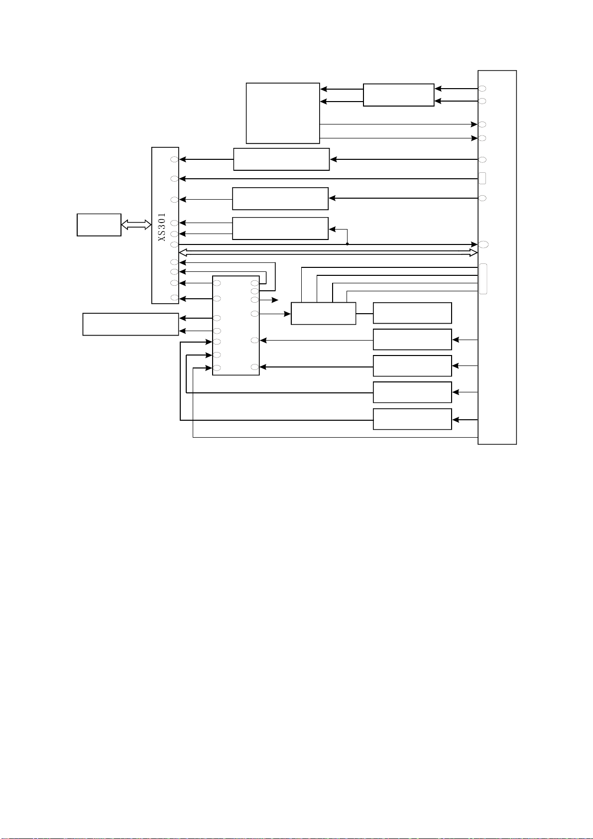
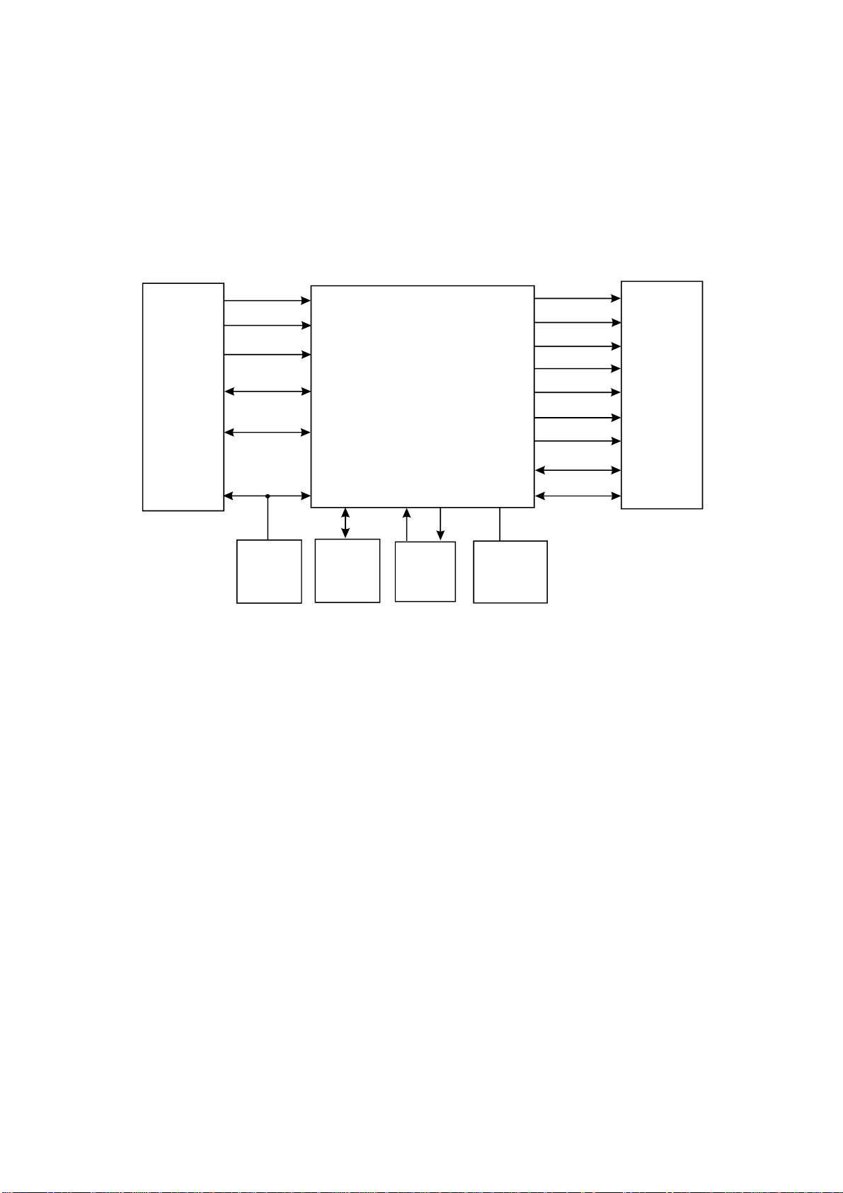
3.1.1Blockdiagramoftheplayer
DV717SIiscomposedofdecodecircuit,servocircuit,audiocircuit,videocircuit,MICcircuitand
powercircuit.Blockdiagramisshownasinthefollowingfigure3.1.1.1:
Remote
control
Microphone
Loader
U205(HCU04)
KEY
U403(HS0038A2)
U6014558
U210(Cs5340)
U302(D5954)
URST#
U401(Pt6961)
Headphone
outputjack
U207(Cs4360)
U201(Mt1389)
U214(FLASH)
U211(SDRAM)
L
R
I C
2
U603
TDA1308
U219
U220
U221
4580
1.8V
U209(LM1117MP-1.8)
H_L
H_R
RT
LS
RS
LFT
CC
LED
LT
A/V
2
I C
OUTPUT
BOARD
2
I C
U202(24LLC02)
Audio
output
Videooutput
Figure3.1.1.1Blockdiagramoftheplayer
-12-
Mainpanel
4973-21
XS401
Xs403
XS402
IR
GND
VFDST
VFDCK
VFDAT
Loaderframe Smallbracket
XS307 Xs306 XS301
Decodeboard
2521S-0
XS201
XS203
Laserhead
XS203
PDAT2
PDAT1
SPDIF
VCC
Y
C
Pr
Y1
Pb
VIEDO
PDAT0
L
R
SL
SR
CC
LFE
+10V
AVboard
7717-0
XS702
Subsidiary
panel
9973-2
CN502
CN502
Powerboard
5DV717-0
AC220V
XS601
MICandheadphoneboard
6717-0
XS603
3.1.3IntroductiontoICoftheplayer
IntroductiontoICoftheplayerisshownasinthefollowingtable:
Semi-finished PCB
name
Power board
5DV717-0
Main panel 4973-2
OK board 6717-0
Decode board
2521S-0
IC model name Location Function
AZ431 U503 Precise voltage regulator
HS817 U502 Photoelectric coupler
FSDH321 U501 Power switch IC
PT6312 U401 Control panel IC
HS0038B3V U402 Remote control receiver
KA4558 U601
TDA1308 U603 Headphone amplifying
NJM4558 U219,U220,U221
HCU04 U205 Phase inverter
HY57V641620HGT-7 U211 SDRAM
LM1117 U209 1.8V voltage regulator IC
24C02 U202 EEPROM
MT1389 C version U201 Decode chip
Operational amplifier (MIC
amplifying)
Operational amplifier (audio
amplifying)
D5954 U302 Servo drive
CS4360 U207 D/A inverter
CS5340 U210 A/D inverter
29LV160BE U214 FLASH
-14-
SectionTwoUnitCircuitPrinciple
3.2.1Laserheadpinintroduction
Laserheadpinintroductionisshowninthefollowingtable:
Pin Name
1 F- Input loader 2.52 2.34 0.46
2 F+ Input loader 2.49 2.49 0.93
3 T+ Input loader 2.53 2.51 0.94
4 T- Input loader 2.58 2.51 0.93
5 C Input MT1389 2.2 2.25 2.04 Disc data signal
6 D Input MT1389 2.2 3.2 2.04 Disc data signal
7 IOA Input MT1389 0.01 3.2 3.21
8 RF Input MT1389 2.21 2.53 1.28 The sum of disc data signal
9 A Input MT1389 2.17 2.22 2.04 Disc data signal
10 B Input MT1389 2.19 2.27 2.04 Disc data signal
11 F Input MT1389 2.07 2.44 2.03 Supplementary signal used in trace
12 GND Ground 0.01 0.01 0 Grounding
13 V20 Input loader 2.04 2.06 2.03 Reference voltage
Signal flow
direction
DVD disc CD disc No disc Function description
Focus error signal is added to two sides of
pick-up focus coil
Trace error signal is added to two sides of
pick-up trace coil
Disc identification signal, CD is 3.3V, DVD
is 0V
14 Vcc Input loader 5.04 5.04 5.02 Supply voltage for loader
15 E Input MT1389 2.06 2.45 2.03 Disc data signal
16 Blanking haning in air 0.01 0 0 unused
17 VR-CD Input loader 0.21 0.01 0
18 VR-DVD Input loader 0.01 0.2 0
-15-
Through the handling inside loader, make
sure MD11 is 180mV when reading CD
Through the handling inside loader, make
sure MD11 is 180mV when reading DVD
19 LD-CD Input loader 0.09 2.1 0 CD laser power control signal
20 MDII Input MT1389 0.21 0.2 0 CD and DVD laser power monitoring signal
High frequency overlapping signal produces
21 HFM Input loader 5.04 5.04 5.02
22 Blanking unused 0.01 0.1 0
23 LD-DVD Input loader 2.21 0.1 0 DVD laser power control signal
24 GND unused 0.01 0.01 0 Grounding
laser with different wave length inside
loader
Note:1.WhenreadingDVD,thereareonlyA,B,C,Dsignals.
2.WhenreadingCD,thereareA,B,C,D,E,Fsignals.
3.RFO=A+B+C+D.
4.Focuserrorsignal=(A+C)-(B+D)Traceerrorsignal=E-F.
3.2.2Discidentificationcircuit
1.Thecircuitschematicdiagramisshownasthefollowingfigure3.2.2.1:
AVCC
R308
100K
V305
R309
10K
R311
10K
IOA
3904-S
R310
100K
R311R0
DQSO
Loader
V303
2SK3018-S
16
17
7
V304
2SK3018-S
Figure3.2.2.1Discidentificationcircuit
2.Workingprinciple:whenreadingCDdisc,theloaderoutputsahighlevel(3.3v)toIOA;when
readingDVDdisc,theloaderoutputsalowlevel(0V)toIOA.
U201
MT1389
114
WhenreadingCDdisc,IOAishighlevel;V304andV305areon;V305collectorelectrodeislow
level;V303drainelectrodeisequaltohangintheair(laserreceiverpipeinsideloaderselectsCD
channel).WhenreadingDVDdisc,IOAislowlevel;V304andV305cutoff;V303ison;V304drain
electrodeisequaltohangintheair(laserreceiverpipeinsideloaderselectsCDchannel).
Note:V303andV304areMOSpipe.
-16-
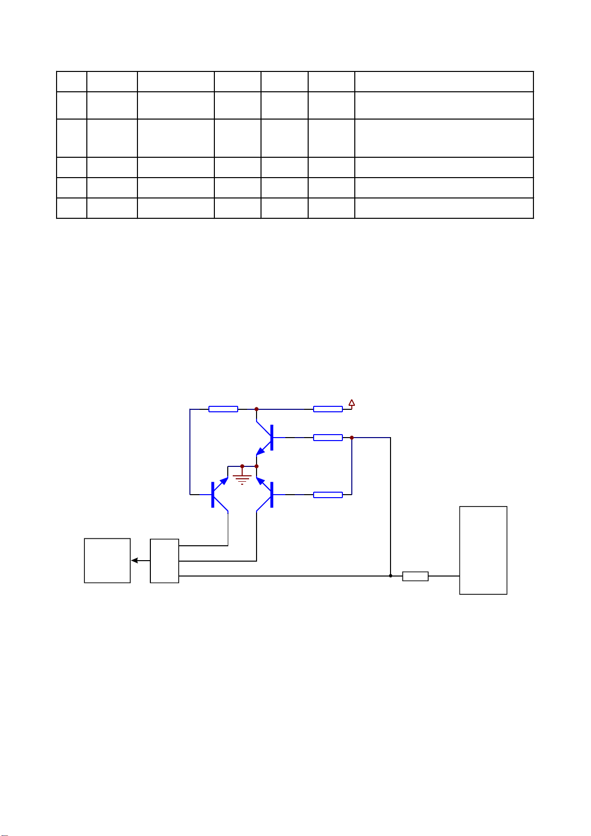
3.2.3Laserpowercontrolcircuit
1.Thecircuitschematicdiagramisshownasthefollowingfigure3.2.3.1:
A
B
U201
C
Loader
G
D
E
F
Figure3.2.3.1Laserpowercontrolcircuitdiagram
2.Workingprinciple:Pin20ofMT1389isVCDlaserpowerstrong/weaksignalinputcheckingpin;
pin21isDVDlaserpowerstrong/weaksignalinputcheckingpin;23pinisVCDlaserpowerdrivecontrol
outputpinandpin22isDVDlaserpowerdrivecontroloutputpin.
WhenreadingVCDdisc,ifpin20ofU201(MT1389)hasdetectedthatthelaseroutputpowerittoo
strong,afterbeingprocessedbyU201(MT1389)internalcircuit,pin23outputvoltageincreasesandthe
on-statedegreeofV302decreasestomakethevoltagesuppliedforpick-updecreaseandthelight
emittingoflaserheadbecomeweak.Ifpin20hasdetectedthatthelaseroutputpoweristoolow,pin23
outputvoltagedecreases;on-statedegreeofV302increasesandthelightemittingoflaserhead
becomestrongtoreachthepurposeofautomaticallyadjustinglaseroutputpower.
WhenreadingDVDdisc,pin21issignalinputcheckingpinandpin22isdrivecontroloutputpin.
TheworkingprincipleisthesamewiththatwhenplayingVCDdisc.
3.Keypointvoltage(unit:V),shownasthefollowingtable:
Key point Position Voltage when reading DVD Voltage when reading VCD
A Emitter electrode of V301 2.9 3.2
B Base electrode of V301 2.2 3.2
C Collector electrode of V301 2.2 0
-17-
D Collector electrode of V302 0 2.2
E Base electrode of V302 3.2 2.2
F Emitter electrode of V302 3.2 2.9
G one end of R228 0.2 0.2
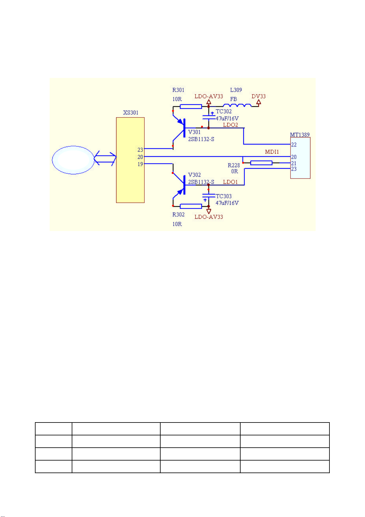
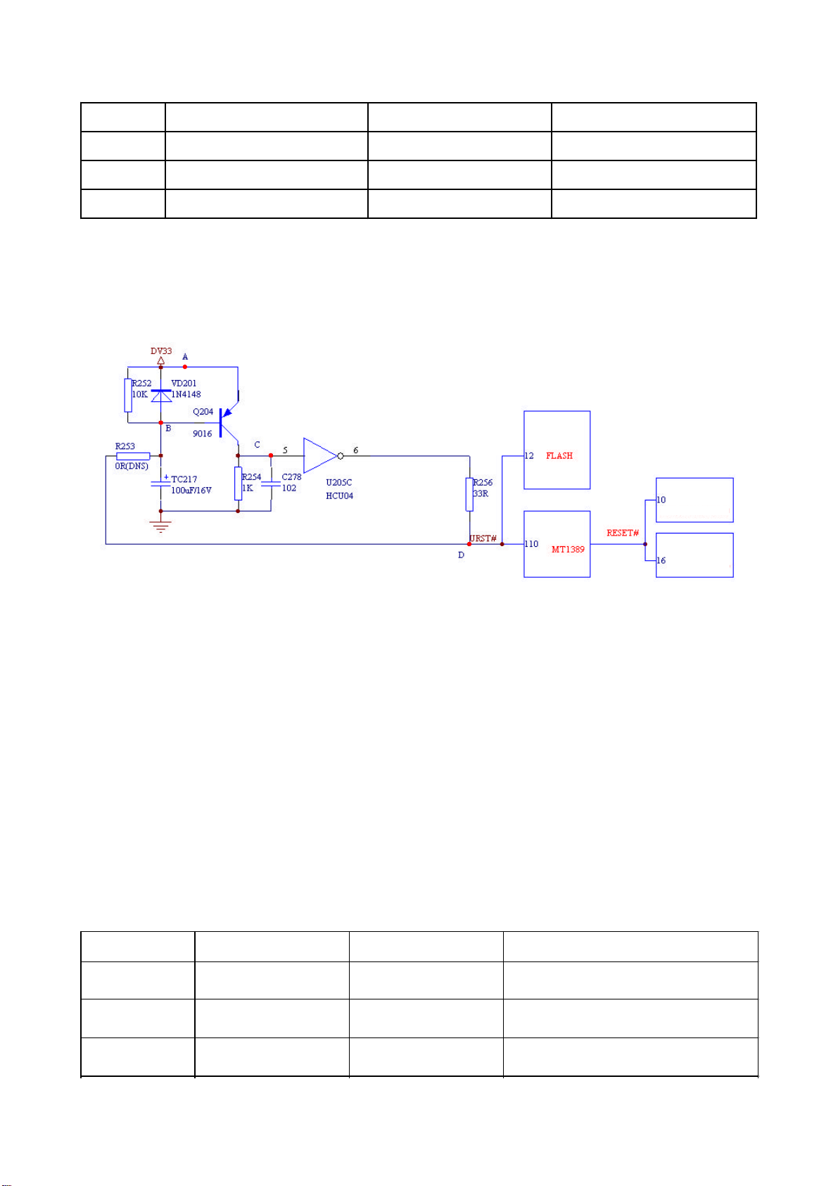
3.2.4Resetcircuit
1.Thecircuitschematicdiagramisshownasthefollowingfigure3.2.4.1:
U207(CS4360)
U201
U210(CS5340)
Figure3.2.4.1Resetcircuitschematicdiagram
2.Workingprinciple:ThetwoendsvoltageofcapacitorT217cannotchangesuddenly,anodeofthe
capacitorbeginschargingfrom0VandnowtriodeQ204ison.Pin5ofphaseinverterU205(HCU04)
outputportishighvoltageandpin6ofitislowvoltagetoresetchipU201(MT1389)andchipU214
(FLASH).Whenchargeofthecapacitoriscloseto3.3V,triodeQ204cutoff;pin5ofphaseinverter
inputportislowlevel;phaseinverteroutputshighvoltagefrompin6andMT1389resetfinishes.After
resetofMT1389,resetsignalisalsogiventosoundD/AconversionchipCS4360andsoundA/D
conversionchipCS5340Vfortheirresetting.
3.Keypointvoltage(unit:V),shownasthefollowingtable:
Key Point Position Voltage Remark
DV33 (pointA) Cathode of diode VD201 3.3V
Point B Anode of diode VD201 After resetfinishes, 3.3V
Point C Pin 5 of phase inverter After reset finishes, 0V
-18-
After power-off, TC217 dischargecurrent from
this point
After reset finishes, voltage rises from0V up to
3.3V.
After reset finishes, voltage decreases from
3.3V down to 0V.
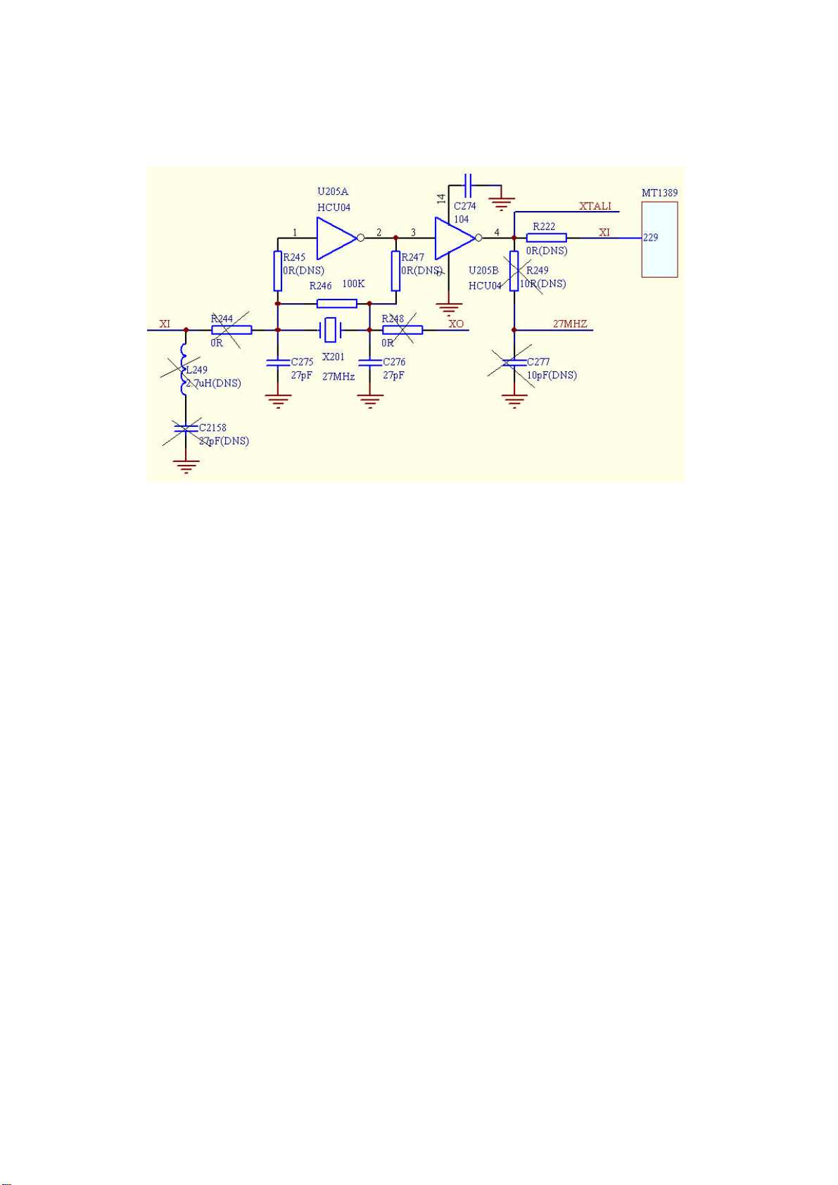
3.2.5Clockcircuit
1.Thecircuitschematicdiagramisshownasthefigure3.2.5.1.
Figure3.2.5.1Clockcircuit
Note:Elementsmarkedwith“X”symbolarethoseunusedinpractice.
2.Workingprinciple:27MHZclockprovidesworkingclockforsystem.Whenpoweringon,capacitor
C275andC276willgenerateaconcussion,soavibrationoccursoncrystaloscillator.Afterseveral
timesoffeedback,astable27MHZclocksignalisfinallygeneratedoncrystaloscillator.Thefunctionof
phaseinverteristoincreasefeedbackcoefficientandforisolation.
3.Thiscircuitmayprobablycausethesetroubles:powersupplynotconnected;notreaddisc;
colourdistortionofpictureandnocolourofpicture.
Note:DCvoltageofpointAandBis1.47Vwheninnormalworking.
3.2.6Discin/outcircuit
1.Thecircuitschematicdiagramisshownasthefollowingfigure3.2.6.1:
2.Electriccurrentwhendiscin/out
Opendisctray:VCCV306CEelectrodeonLOAD+ElectricmachineLOAD-V308CE
electrodeonR326Ground
Whennotopeningdisctray,pin51and39ofU201(MT1389)arelowlevel.Whenopeningdisctray,
pin51ofU201(Mt1389)sendsahighlevel;V308ison;V308collectorelectrodechangesintolowlevel;
→→
→→→→→
-19-
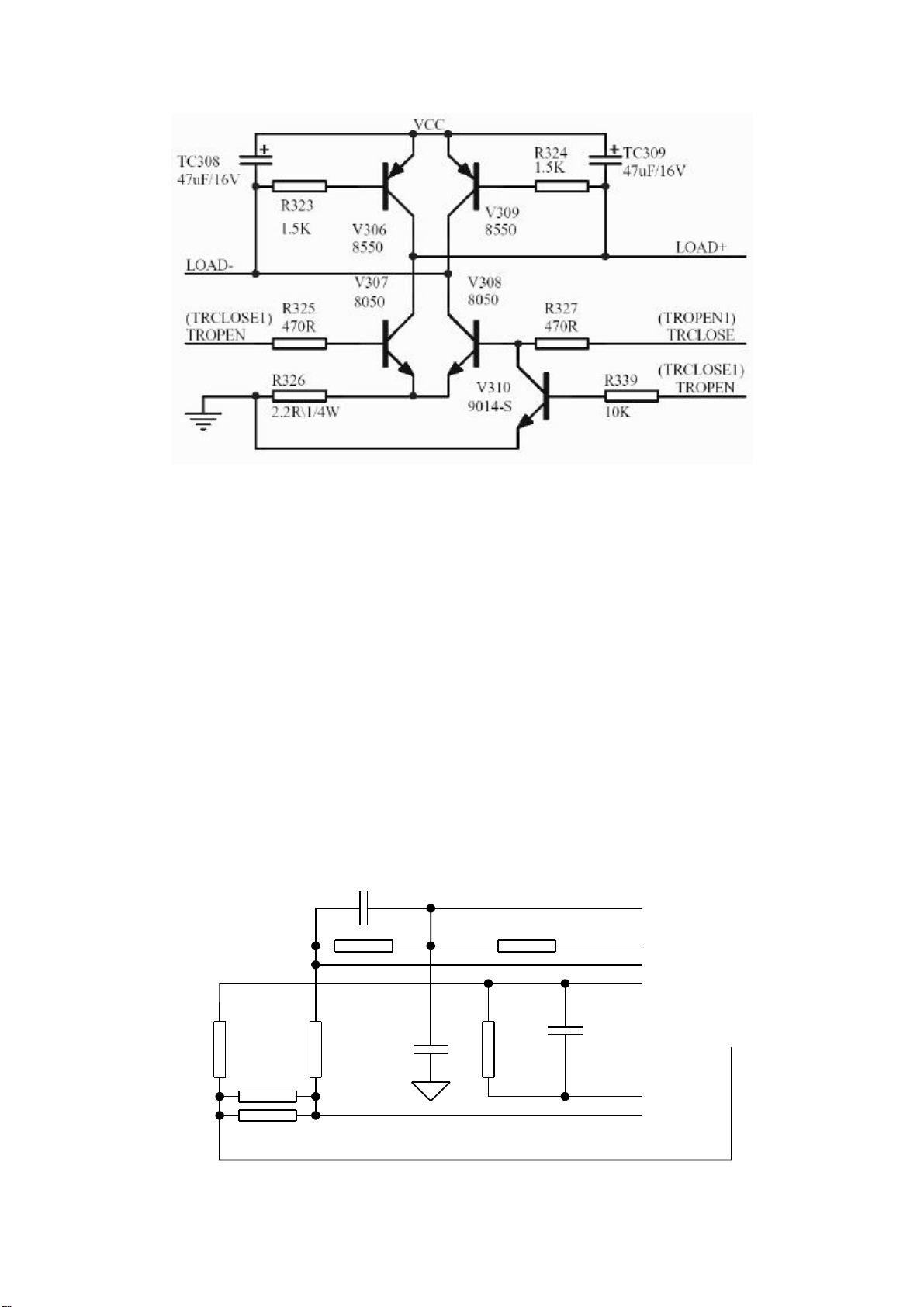
Figure3.2.6.1Discin/outcircuit
LOAD-changesintolowlevel;V306baseelectrodechangesintolowlevel;V306ison.V306collector
electrodechangesintohighlevelandLOAD+changesintohighlevel.
Closedisctray:VCCV309CEelectrodeonLOAD-ElectricmachineLOAD+V307CE
electrodeonR326Ground
→→
→→→→→
whenclosingdisctray,pin39ofU201(Mt1389)sendsahighlevel;V307ison;collectorelectrode
changesintolowlevel;LOAD+islowlevel;baseelectrodethroughR324andV309islowlevel;V309is
on;V309collectorelectrodechangesintohighlevel;LOAD-changesintohighlevel.
3.2.7Mainaxisbrakingcircuit
1.Thecircuitschematicdiagramisshownasthefollowingfigure3.2.7.1:
R317
R320
2200pF
680K
C308
DNS
R318
R322
680K
0R
OPO
ADIN
OP+
C310
2200pF
V1P4
SP-
OP-
SP+
R319
150K
R321
R340
C307
150K
1R
1R
Figure3.2.7.1mainaxisbrakingcircuitdisgram
-20-
Theequivalentcircuitisshownasthefollowingfigure:
R317
R320
2200pF
680K
C308
DNS
34
47
35
36
12
D5954
11
MT1389
A/D
DMO
37
5
OPO
0R
R318
R322
680K
M
ADIN
OP-
OP+
C310
2200pF
V1P4
SP-
SP+
R319
150K
R321
R340
C307
150K
1R
1R
2.Workingprinciple:
Toprolongtheservicelifeofelectricmachineanddecreasetheinfluenceofstart-upconcussion
currenttothemachine,whenthereisdiscin,thedevelopmentpersonneldesignthemainaxiselectric
machineinrunningstatealways.Eventhough“STOP”buttonispressed,discwillnotstoprunning
immediately.Thuswhenpressing“OPEN”button,abrakingsignalisrequiredtomakethemainaxis
electricmachinestoprunningtofulfillthecompletionofopeningdisctrayinashortperiod.Inthecourse
ofplayback,
Press“OPEN"buttonandmainaxisdrivesignaldisappears.Forthereasonofinertia,themainaxis
electricmachineisstillinrunningstate,andnowtheinducedvoltageachievedbytheinduced
electromotiveforcewhichisgeneratedbyelectricmachine'srunningonsamplingresistorR321and
R340outputsfrompin34throughresistorE319,R320andpin36ofMT1389afterbeingprocessed
insideMT1389andmagnified,thensendstopin47ofMT1389throughR13;afterA/Dconversionand
thecorrespondingprocessinginsideMT1389,aninstantelectricmachinereversalbrakingsignalis
outputtedfrompin37ofMT1389tomakethemainaxiselectricmachinedecreasespeed.When
MT1389detectsthediscstopsrunning,disctraywillopentoensurethatdiscwillnotrunwhendisctray
opens.
3.Keypointvoltage(unit:V),shownasthefollowingtable:
Key point Position Normal working voltage (V)
Voltage change when door is
opened (V)
SP+ pin 11 of D5954, pin 5 of XS303 3.79
SP- pin 12 of 5954, pin 6 of XS303 1.38
OP+ pin 36/B of MT1389 1.38
OP- pin 35/A of MT1389 1.53
-21-
3.79→0.70→1.80
1.38→3.40→1.80
1.38→3.10→1.80
1.53→3.08→1.98
OPO pin 34/C of MT1389 2.44
2.44→0.40→2.50
ADIN pin 47/D of MT1389 2.44
2.41→0.41→2.44
DMSO pin 5 of D5954 1.42 1.42
VIP4 pin 30 of MT1389 1.41 1.41
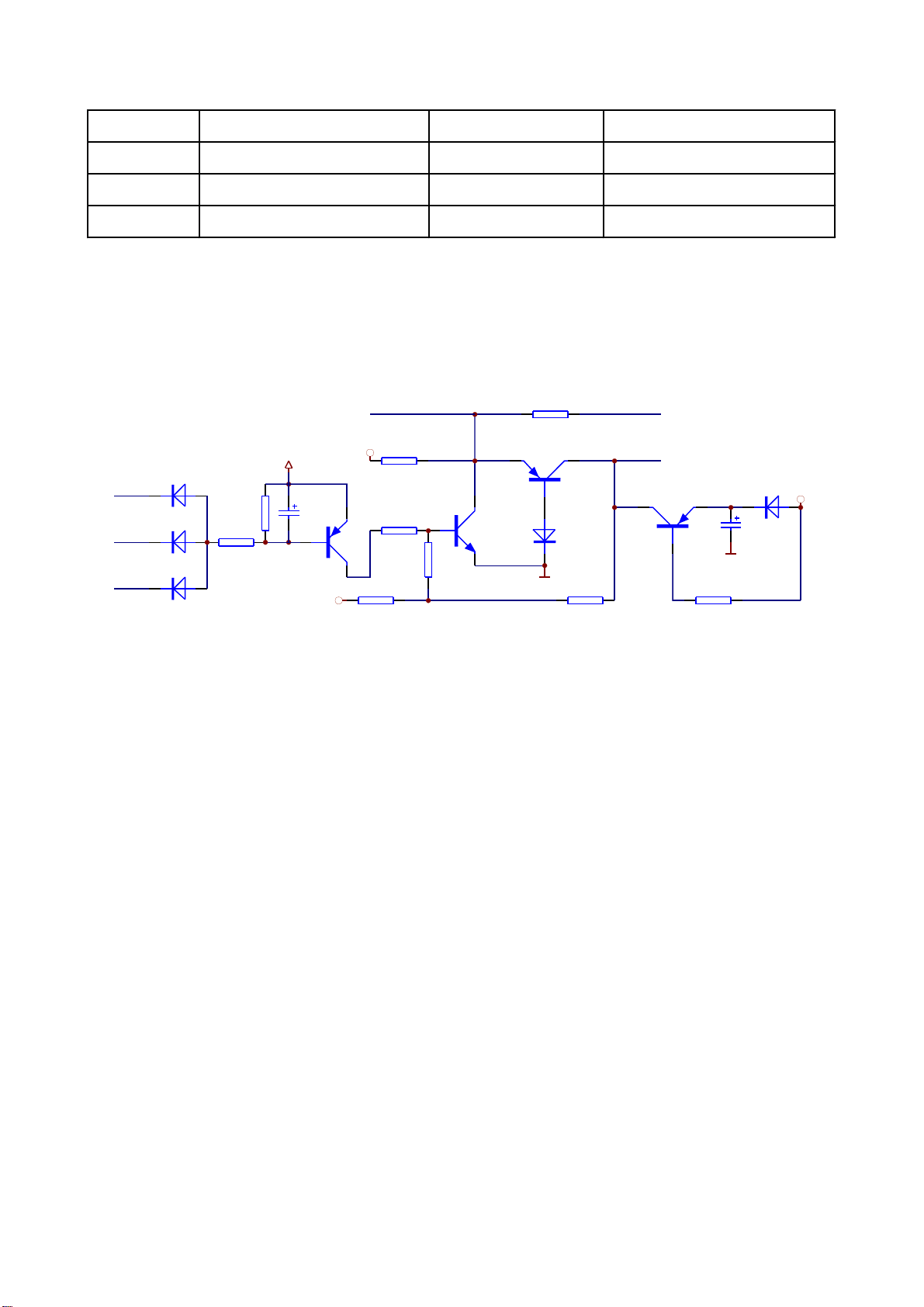
3.2.8Mutecircuitandpower-offquietingcircuit
1.Thecircuitschematicdiagramisshownasthefollowingfigure3.2.8.1:
MUTE1
A
MUTE2
B
MUTE3
C
VD207
1N4148
VD208
1N4148
VD209
1N4148
VCC
R2101
10K
D E
R2102
1K
TC238
100uF/10V
Q211
1015-S
-9V
MUTEA
+9V
F
R2105
10K
R2103
1K
R2104
1K
G
R2106
10K
k
R21070R(DNS)
Q218
H
1015-S
Q212
2SC1815-YS
AGND
I
VD205
1N4148
J
R2108
10K
VOICE-DET
MUTE-1
Q219
1015-S
L
M
AGND
R2109
10K
VD206
1N4148
VCC
TC235
100uF/10V
Figure3.2.8.1Muteandpower-0ffquietingcircuit
2.Workingprinciple:underthecontrolofICtoMT1389,CS4360sends3mutecontrolsignals,
2
MUTE1,MUTE2,MUTE3frompin28,25and18whichisaddedtomutecircuit.Thegeneratedmute
controlsignalMUTE-1isaddedtothebaseelectrodeofeachswitchingtubeQ205-Q210of6-path
analogchanneltomaketheswitchingtubeandmakeaudiosignalbypassintogroundtoreachthe
purposeofmute.Theworkingmechanismisthatwhennoaudiosignalcomestoacertainpath,CS4360
changesthemutecontrolsignalcorrespondingwiththispathtohighlevel.AfterpressingMUTEbutton,
3-pathmutesignals allchangetohighlevel.
Whenworkingnormally(playingdiscs),onlyonepathsignalofthe3-pathsignals,MUTE1,MUTE2
andMUTE3changesintolowlevel,nowQ211ison.ThecollectorelectrodeofQ211ishighlevel;Q212
isalsoonanditscollectorelectrodeislowlevel;Q218iscutoff;MUTE-1islowlevelandsoundoutputs
normally.
Whenmuting,MUTE1,MUTE2andMUTE3outputtedbyCS4360allchangeintohighlevel.Atthis
time,forthebaseelectrodeofQ211ishighlevel,Q211iscutoffandQ212isalsocutoff.Theemitter
electrodeofQ218changesintohighlevelandalsoison.+9Vvoltageis addedtoMUTE-1through
EmitterCollectorofQ218,theoutputtedhighlevelisaddedtothebaseelectrodeofswitchingtube
Q205~Q210.Theswitchingtubeisonandsoundisbypassedtoground.
-22-

Power-offquieting:whenworkingnormally,becausethereisnoforwardbias,Q219isincutoffstate.
Whenpoweringoff,+9VdisappearsandthebaseelectrodeofQ219changesintolowlevel.For
capacitorTC235dischargeishighleveltotheemitterelectrode,Q219ison.ThedischargeofTC235
makesMUTE-1outputshighlevelandaddtoeachswitchingtubethroughEmitter-CollectorofQ219to
maketheswitchingtubeonandsoundisbypassedtogroundtorealizethefunctionofpower-offquieting.
Power-onquieting:whenpoweringon,VCCisconnectedtopowersupply,voltageofthetwoends
of Tc238cannotchangesuddenly.ThebaseelectrodeofQ211changesintoabout5VandthenQ211is
cutoff,Q212iscutoffandMUTE-1changesintoabout1.68toperformpower-onquietingfunction.
Thefunctionof-9Vvoltageinthefigureistoensurethesecurecutoffofeachswitchingtubewhen
circuitisworkingnormally.
3.Keypointvoltage(unit:V),shownasthefollowingtable:
KEY POINT
NO MUTE
MUTE
INSERT
MICROPHO
NG
A B C D E F G H I J K L M
0.02 0.02 0.02 0.53 4.55 5.2 0.84 0.12 -0.15 -4.27 -4.27 5 5
5.02 5.02 5.02 5.18 5.23 -3.86 -3.87 1.67 0.81 1.63 -3.87 5 5
0.02 5.02 0.02 0.53 4.52 5.2 0.64 0.12 -0.15 -4.27 -4.27 5 5
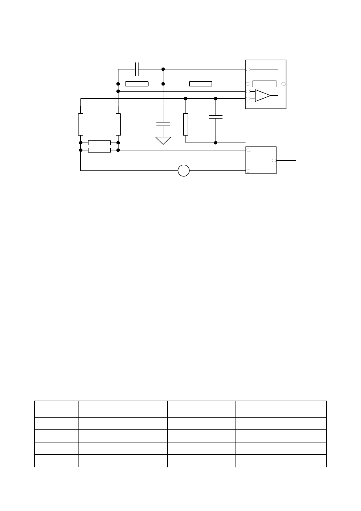
3.2.9Servocircuit
1.DK1005SadoptsSANYO62decoderandMTKdecodesolution(MT1389+FLASH(16M)+
SDRAM(64M)).Theservocircuitismainlycomposedoffrontsignalprocessing,digitalservo
processing,signalprocessingICT1389anddrivecircuitD5954,inwhichMT1389isthemain
componentofdecodecircuitatthesametime.
2.Thecircuitfunctionalblockdiagramisshownasfigure3.2.9.1.
TheExplanationtotheblockdiagram:Afterpoweringonordiscin,discidentificationcircuit
identifiesthediscinsertedintoloader,andjudgeswhetherthediscisCDorDVDtoconductthe
correspondingcontrol.Atthesametime,MT1389adjustslaseroutputpowerthroughlaserpower
controlcircuit.Pin20ofMT1389isVCDlaserpowerstrongness/weaknessdetectingsignalinputpin,
pin21isDVDlaserpowerstrongness/weaknessdetectingsignalinputpin,pin23isVCDlaserpower
drivecontroloutputpinandpin22isDVDlaserpowerdrivecontroloutputpin.WhenreadingVCDdisc,
ifpin20detectslaseroutputpoweristoostrong,outputvoltageofpin23ofMT1389increasesandon-
stateofV302decreasestomakethevoltageprovidedforpick-updecreaseandlightemissionoflaser
headbecomestrong.
-23-
Discin/outelectric
machineand
detectingswitch
Discin/outcircuit
TROUT
TRIN
TROPEN
TRCLOSE
39
51
48
49
Loader
Feedelectric
machineonloader
23
20
19
18
17
7
2
1
4
SL+
3
SL-
DVDlaserpowercontrol
VCDlaserpowercontrol
Discidentificationcircuit
15
17
17
18
23
26
28
U602
D5954
14
13
SP-
12
SP+
12
5
1
IOA
A、B、C、D、E、F(a、b、c、d)
Mainaxis
brakingcircuit
Mainaxiselectric
machineonloader
Integrationcircuit
Integrationcircuit
OPO
ADIN
OP-
OP+
22
20
21
23
114
47
34
35
36
MT1389
Integrationcircuit
Integrationcircuit
Figure3.2.9.1Servocircuitdiagram
Afterloaderreadingdiscinformation,A,B,C,D,E,FsignalsaresentouttoMt1389(DVDonly
hasA,B,C,Dsignals),andtheninputtedfrompin2~11,18,19ofMT1389.Afterbeingamplifiedand
processedbythepre-amplifierinsideMT1389,nowsignalsareseparatedtotwopartsforprocessing
insideMt1389:
AfterbeingprocessedbydigitalservosignalcircuitinsideMT1389,onepartofsignalform
correspondingservocontrolsignalsandoutputFOO,TRO,DMO,FMOdigitalservocontrolsignalsfrom
pin42,pin41,pin37,pin38ofMt1389respectively,thenchangeintoanalogservocontrolsignalFOSO,
TRSO,DMSO,FMSOthroughintegrationcircuitcomposedbyresistorcapacitor,andsendtodriver
circuitBA5954foramplificationtobringalongfocuscoil,tracecoil,mainaxiselectricmachineandfeed
electricmachineafterdriveamplification.Amongthese,focusandtraceservoareusedtocorrect
objectivepositionaccurately;feedservoisusedtobringalonglaserheadtomakeradiallarge-scale
movewhichbelongstothepreliminaryadjustmenttopick-upposition;andmainaxisservoisusedto
controlmainaxiselectricmachinetomakeitreadsignalsinmeansofconstantlinearvelocityandbring
alongdisctorotate.
-24-

AfterprocessingofamplificationbyVGAvoltagecontrolamplifierandequalizationfrequency
compensationinsideMT1389,anotherpartofsignalsarechangedintodigitalsignalsthroughinternal
A/Dconverter.WhenloaderisreadingCD/VCDsignals,thesesignalsareconductedEFMdemodulation
insideMT1389,andthenoutputtedtolatterstageforAVdecodingafterfinishingCIRC(Cross
InterleavedReed-SolomonCode)errorcorrectioninside.WhenloaderisreadingDVDsignals,these
signalsareconductedESMdemodulationinsideMT1389,andthensenttolatterstagefordecoding
afterfinishingRSPCerrorcorrectioninside.
Theotherpartofservoisopen/closedisctraycircuit.Afterpanelorremotecontrolleremits
open/closedisctraysignaltoMT1389,inusualconditions,TROPENandTRCLOSEsentoutbypin39,
51ofMt1389arebothlowlevel,whensignalof“open”comes,afterMt1389makesdiscstoprotating
throughmainaxisbrakingcircuit,TRCLOSEissethightomakeopen/closeelectricmachineonloader
frameruntobringalongdisttraytoeject.AfterdisctrayejectingtoproperSignalofopeningtoproper
position(TR_OUT)issethighlevel(0V)throughthedetectingswitchonloaderframe,MT1389pulls
downTRCLOSEandopen/closeelectricmachinestoprunning.WhenMT1389receiving“close”signal,
TROPENissethighlevelbyMT1389,open/clodeelectricmachinetunsconverselytobringalongdisc
traytoclose.Afterdisctrayclosingtoproperposition,signalofclosingtoproperposition(TR_IN)isset
lowlevelthroughthedetectingswitchonloaderframe,MT1389pullsdownTROPENandelectric
machinestopsrunningtofinish“close”process.
3.Explanationtoservoterms
FOO:whenrotating,discmayprobablymoveupwardsordownwardsslightlytomakethefocusof
laseremittedbypick-upcannotjustlyfallondatapitofdisc,sopick-upisrequiredtomoveupwardsor
downwardstomakefocusaimatdatapitjustly.Whenpick-upismovingupwardsordownwards,it
meansthatpick-upismakingfocusacts.
TRO:datainformationissaveindiscinformoftracks.Theprocesswhenpick-upmovesfromone
tracktoanotheronetoreaddataistrace.Inthisprocess,itisobjective,buttheentirepick-up,that
movesforwardsorbackwards,andthemovingrangeisverysmall.
FMO:similartoactsoftrace,theactsoffeedarelargerthanthoseoftrace.Feedconductsalarge
scalemovementfirstly,andthentracemovesslightlyinthisrange.Feedmovesforawhile,anddoes
notmoveforanotherwhile;buttracemovesallthetime.Feedisroughadjustmentandtraceisfine.
DMO:itisthetopthatholdsupdisc.Itsrotationspeeddecidesthatofdisc.Itsrotationisgenerated
byanindividualDCelectricmachine,inwhichrotationspeedofDVDistwiceoverthatofCD.
Hint:Inordertoobservetheseprocesses,youmaytakedownuppercoverofthemachine,and
thentheloadercoverboard.Whenpoweronwithnodiscinordiscinafterdiscout,youmayobserve
thatpick-upreturnstoinnerringfirstlyandthenspringsbackforalittledistance,whichisfeedprocess.
Thenpick-upwillemitlightandyoumaynoticetheobjectivemovesupwardsanddownwards,whichis
focusprocess.Inface,inthesametimeoffocus,theobjectivealsomovesupwardsandbackwardsto
-25-
Maketraceacts.Becausetherangeissmall,itisnoteasytoobserve,andmeanwhileDEMOdisctray
alsorotatesslightly,whichisDEMOacts.
3.2.10Decodecircuit
1.Decodecircuitblockdiagramisshowninthefollowingfigure3.2.10.1:
FLASH
PWR
PRD
PCE
A0~A20
AD0~AD7
URST
Reset
circuit
MT1389
SDA
SCL
EEPROM
24C02
Figure3.2.10.1Decodecircuitblockdiagram
27M
Clock
V18
1.8Vvoltage
regulating
U206
SDCLK
SDCKE
DCS
DRAS
SWE
SDRAM
DQM0
DQM1
DQ0~DQ15
MA0~MA11
2.Workingprinciple:thisdecodecircuitismainlycomposedofMt1389,SDRAMandFLASH.The
importantconditionsfordecodecircuitworking:
(1)Reset:refertoresetcircuitworkingprinciplefordetails.
(2)Clock:thissystemadopts27Mexternalclockinputandproducestheclocksignalrequired
insidesystemthroughinternalfrequencydoublingcircuit.
(3)Power:decodechipadoptstwogroupsofpowersupply:3.3Vand1.8V,inwhich1.8Vis
providedforinternallogiccontrolcircuit,sowecallcarevoltage.
Afterpoweron,resetcircuitperformsresettoCPU(8032)andFLASHinsideMt1389,decodechip
outputsresetsignalatthesametimetoperformresettoothercircuit.Aftersystemreset,readsignalis
sentouttoFLASHtoreadtheinformationsavedinFLASHandmachinedisplayspoweronpicture.
Servosystembeginstoworktocheckwhethermachineclosestoproperpositionandwhetherswitchis
turnedoff,ifnot,closeactionisperformed.Afterdoordetectswitchisturnedoff,themachinebeginsto
carryoutthepreparationworkforreadingdiscandpaneldisplayatthesametime.
Playbackprocess:laserheadpicksupdiscsignalfromdisc,afterbeingprocessed byservo
system,andsendsittodecodecircuitfordecoding,andsignalafterbeingdecodedissavedinSDRAM
-26-