

Page 1
Confidential
Edition
Approved by
BBK COMPANY
DP710/DP810
Distribution
Approved by
Service Manual
Page 2

-
-
Contents
s
s
1. Cover
2. Contents
3. Specifications
3.1 Product Overview
3.2 DP710 Specification
3.3 DP810 Specification
4. Warning
5. Disassembly
5.1 Disassembling the Outer Screws and the Strap Holder
------------------------------------------------------------------------------------------P1
------------------------------------------------------------------------------------P2~P5
-------------------------------------------------------------------------------P6~P10
------------------------------------------------------------------P6~P8
------------------------------------------------------------------ P9
------------------------------------------------------------------ P10
------------------------------------------------------------------------------------P11
-------------------------------------------------------------------------------P12~P35
Bottom Screws -------------------------------------------------------------------P12
Right Screws -------------------------------------------------------------------P12
Left Screws and Strap Holder ---------------------------------------------------P12
---------------------
P12
5.2 Disassemble Back Cover Unit
Notes on the Diassembly of the Back Cover -------------------------- P13
LCD --------------------------------------------------------------------------------LCD Sponge and Paste --------------------------------------------------------P14
Back Button Board and Fastening Screws ---------------------------------- P14
Direction Button ------------------------------------------------------------------P15
Direction Button Cover --------------------------------------------------------P15
W-T Button -------------------------------------------------------------------------P15
4 Function Buttons -----------------------------------------------------------P15
Direction Button Cover -----------------------------------------------------P16
TFT Protector ----------------------------------------------------------------P16
5.3 Disassemble the Battery Cover Unit
-----------------------------------------------------P13~P16
---------------------------------------------
P14
P17
Page 3

Battery Cover Shaft -----------------------------------------------------------P17
-
-
-
Battery Cover Sheet and Fastening Screws------------------------------------ P17
5.4 Discharge the Main Board
Disassemble the Main Board
Notes on the Disassembly of the Main Board
Main PCB Sponge-------------------------------------------------------------------P19
MC_Pet P19
Connection betwee the LENS FPC and the M/B
Connection between the CCD FPC and the M/B
Disassemble M/B Fastening Screws
Xe Line(+/-)
Trigger Line -------------------------------------------------------------------P20
MC Line(+/-) --------------------------------------------------------------------AF Light Line(+/-) --------------------------------------------------------------P20
-------------------------------------------------------------------------
------------------------------------------------------------------ P20
--------------------------------------------------
------------------------------------------------
--------------------------
--------------------------P19
--------------------------P19
--------------------------------------P19
P18~P20
P18
P18
P20
MIC Line(+/-) -----------------------------------------------------------------P20
Speaker Line(+/-) -----------------------------------------------------------------P20
5.5 Disassemble the Lens Unit
Disassemble the Lens Fastening Screws
CCD FPC
LENS FPC
5.6 Disassemble the Body Unit
Disassemble the Body Fastening Screws
Disassemble the Main Capacitor Unit
Main Capacitor
CAP Board -------------------------------------------------------------------
MC Line(+/-)
---------------------------------------------------------------------------P21
---------------------------------------------------------------------------P21
-----------------------------------------------------P21
---------------------------------- P21
--------------------------------------------------------P22~P27
---------------------------------- P22
--------------------------------------P23
----------------------------------------------------------- P23
P23
-------------------------------------------------------------P23
Page 4

-
-
-
-
-
-
Disassemble the Speaker
Disassemble the Power PCB Unit and Fastening Screws --------------- P25
Disassemble the Battery Buffer and Fastening Screws---------------------- P26
Disassemble the Battery Buffer Thinking Proof-------------------------------P26
Disassemble the Reflector Umbrella ----------------------------------------P27
Reflector Umbrella --------------------------------------------------------P27
Xe Line(+/-) ------------------------------------------------------------------ P27
-------------------------------------------------------P24
Xe Tube and Silicone -----------------------------------------------------Trigger Line and Cu Foil --------------------------------------------------P27
5.7 Disassemble the Middle Cover Unit
Disassemble the Flash Panel and Fastening Screws ------------------------P28
AF_LED ---------------------------------------------------------------------------P28
AF_LED Line(+/-) -------------------------------------------------------------P28
Disassemble the Middle Cover and the Front Cover
Disassemble the Top PCB Unit and Fastening Screws
Disassemble the Power Key ---------------------------------------------------P30
Disassemble the Modedial board Brush Fastening Screws------------------P31
Disassemble the Modedial Body Board Fastening Screws------------------ P31
Disassemble the Mold LED Light Guide
P27
-------------------------------------------P28~P34
--------------------
--------------------
---------------------------------
P29
P30
P31
Mode Ball and Modedial Spring
Shutter Button and Shutter button Spring ------------------------------------P33
Disassemble the Modedial Unit
5.8 Disassemble the Front Cover Unit
Disassemble the MIC ----------------------------------------------------------- P35
Disassemble the Self LED Leader ---------------------------------------------P35
--------------------------------------------
--------------------------------------------
--------------------------------------------
P32
P34
P35
Page 5

6. Test Statio
n
-
-
-
-
-
-
l
--------------------------------------------------------------------------------------P36~P43
Test Items and Procedure for Main parts while being Replaced
List of Measurement Instruments used for the Test ---------------------------P36~P38
Operation Procedure for each Test Item --------------------------------------------------P39
Operation Procedure for Self test, Lens test, and EFA
Run- in Test ------------------------------------------------------------------------------P39
End Voltage Setting --------------------------------------------------------------- P40
ISO Sensitivity, Shutter Calibration, CCD Bad Pixel Compensation,
Color Calibration, White Image Auto Shot (5-in-1)
Auto Focus Inspection ------------------------------------------------------------------ P41
Flash Calibration Operation (Cali Flash)
USB ID Writing Operation ----------------------------------------------------------
7. Circuit Diagram
-------------------------------------------------------------------------
--------------------------------------
---------------
--------------------
---------------
P36
P39
P40
P42
P42~P43
P44~P62
Precautions -------------------------------------------------------------------------------------P44
M/B -------------------------------------------------------------------------------------------CCD FPC ------------------------------------------------------------------------------------TOP/B ------------------------------------------------------------------------------------------P62
8. Too
9. BOM
--------------------------------------------------------------------------------------------- P63~P64
------------------------------------------------------------------------------------------P65~P66
P45~P60
P61
Page 6
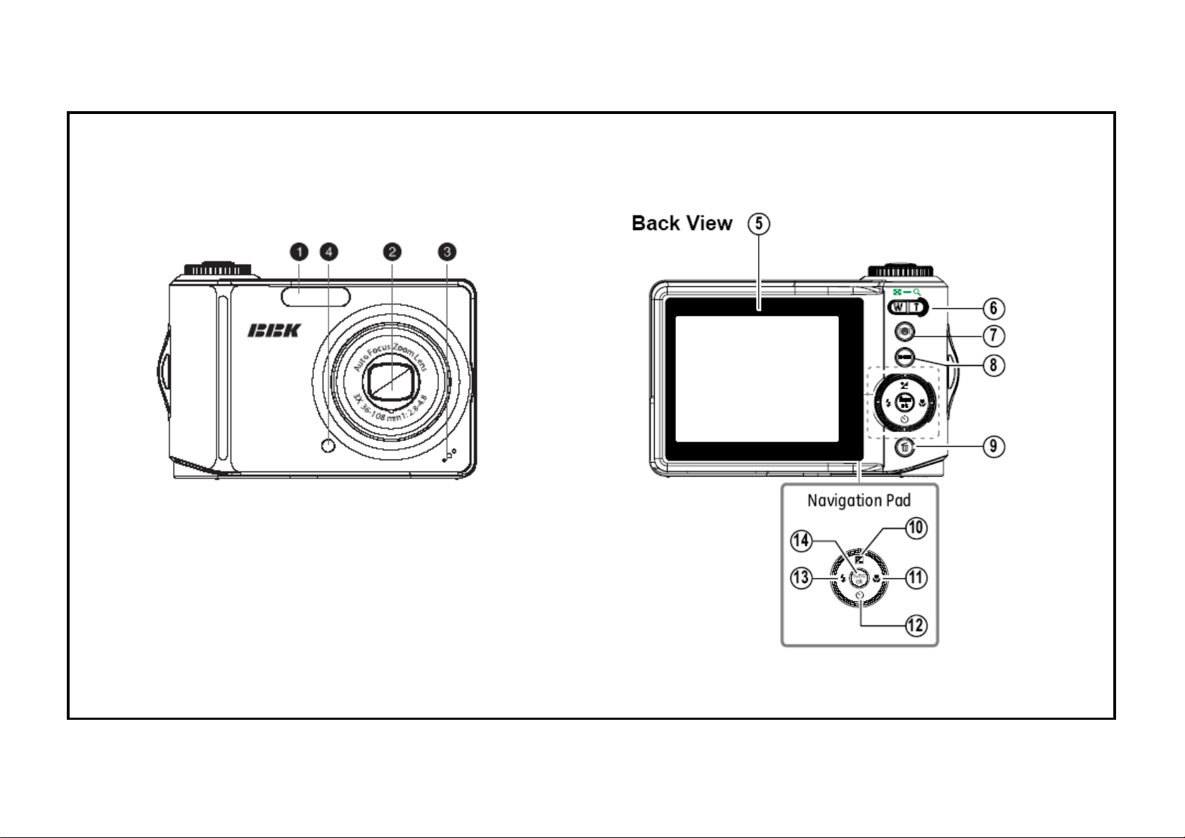
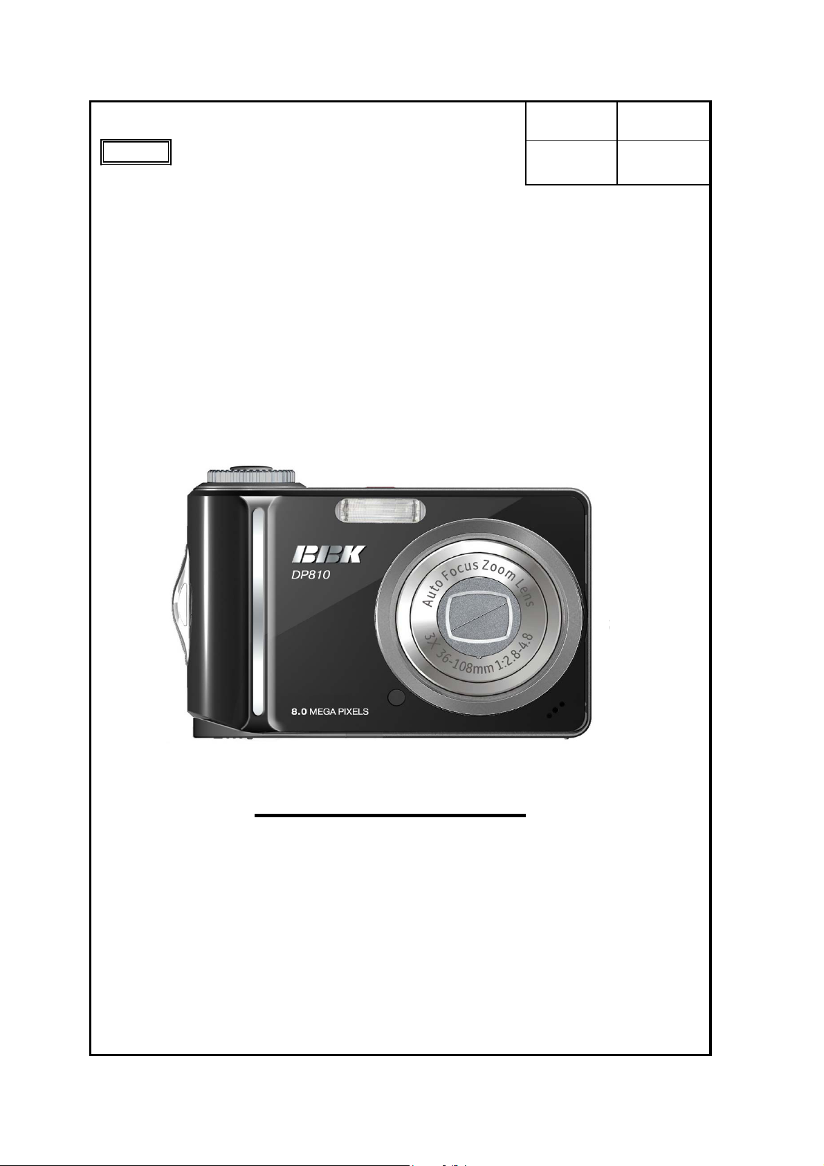
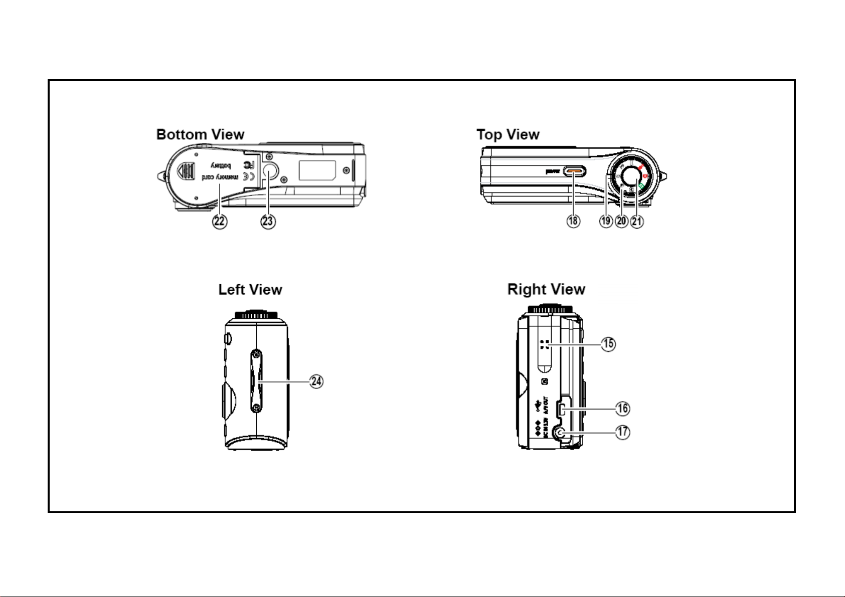
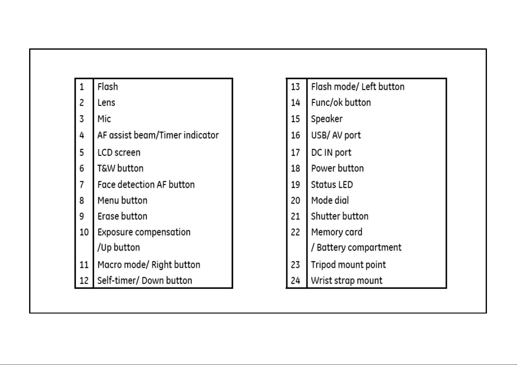
Specifications
Product Overview
Front View
###
Page 7
Page 8
Page 9
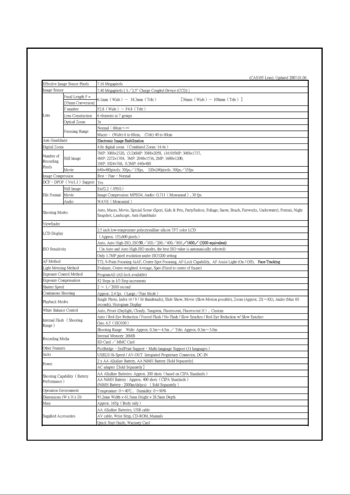
DP710 Specifications
Page 10
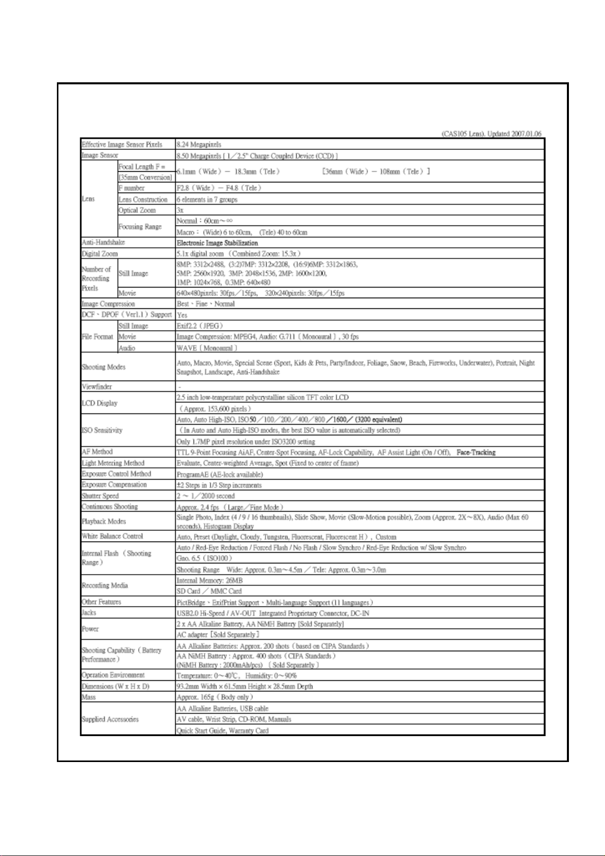
DP810 Specifications
Page 11
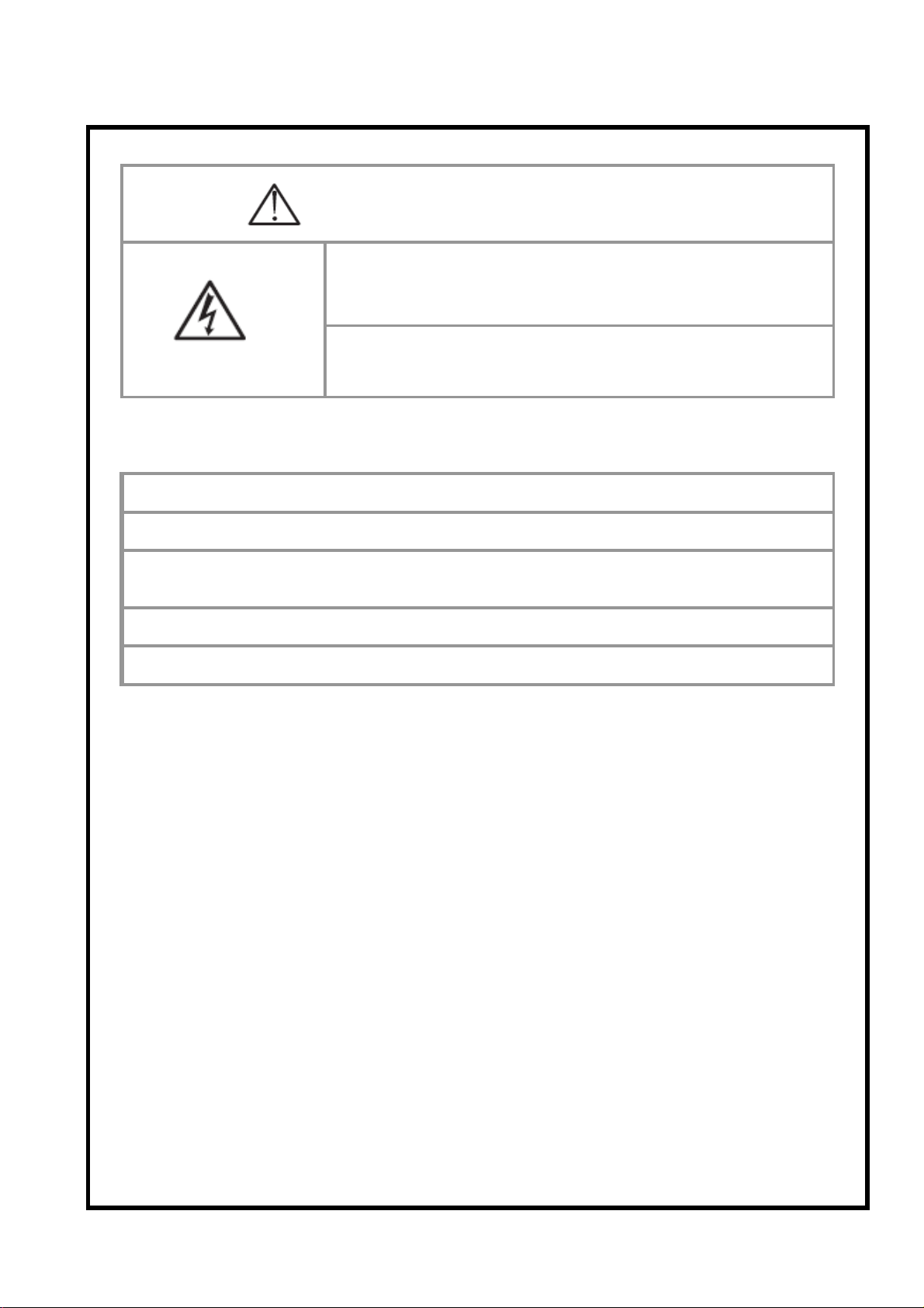
Warning
There is electrical current inside the camera. Please
●
be careful while removing the cover to avoid electric
shock.
While removing the cover, please discharge the large
●
capacitors according to the Repair Manual.
Description of the use of lead-free solder in the product.
●
●
●
●
Note:
In this product, lead-free solder is used.
During the soldering, the Unleaded Soldering Machine and solder iron must be used.
It is not allowed to mix the lead-free solder and the lead-alloy solder.
The Soldering Machine cannot be used together with the solder iron.
It is necessary to take out the SD card and the battery before disassembling the camera.
★
While disassembling the camera, it is necessary to pay attention to the locations
★
of the soldering joints and the soldering methods of various conducting wires, the
screw types, and the fastening methods for screws.
There is weak static current in the electronic device, so it must be connected to the ground.
★
Page 12
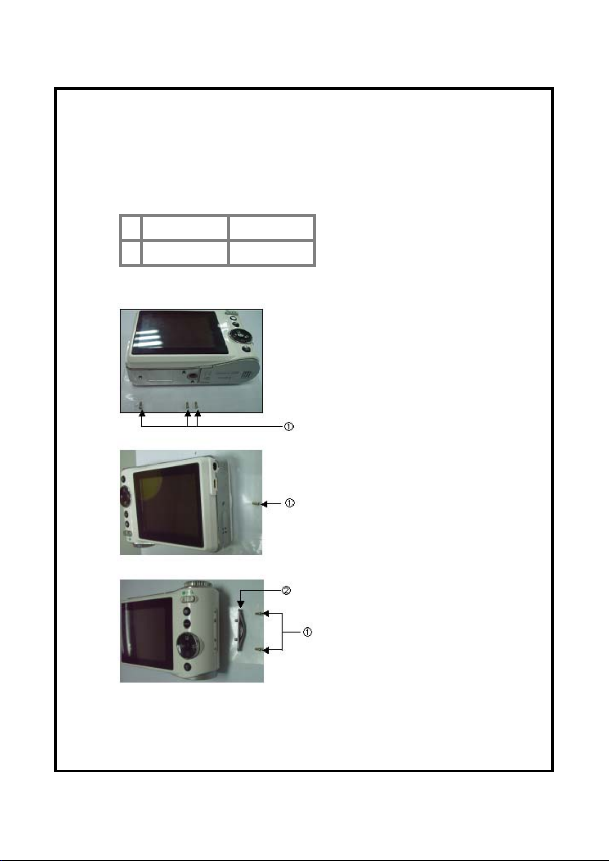
Disassembly
Disassembling the Outer Screws and the Strap Holder
CR074161399 Outer Screws
①
CR073030699 Strap Holder
②
①
Note: After ① is disassembled, apply force gently to remove ②.
Page 13
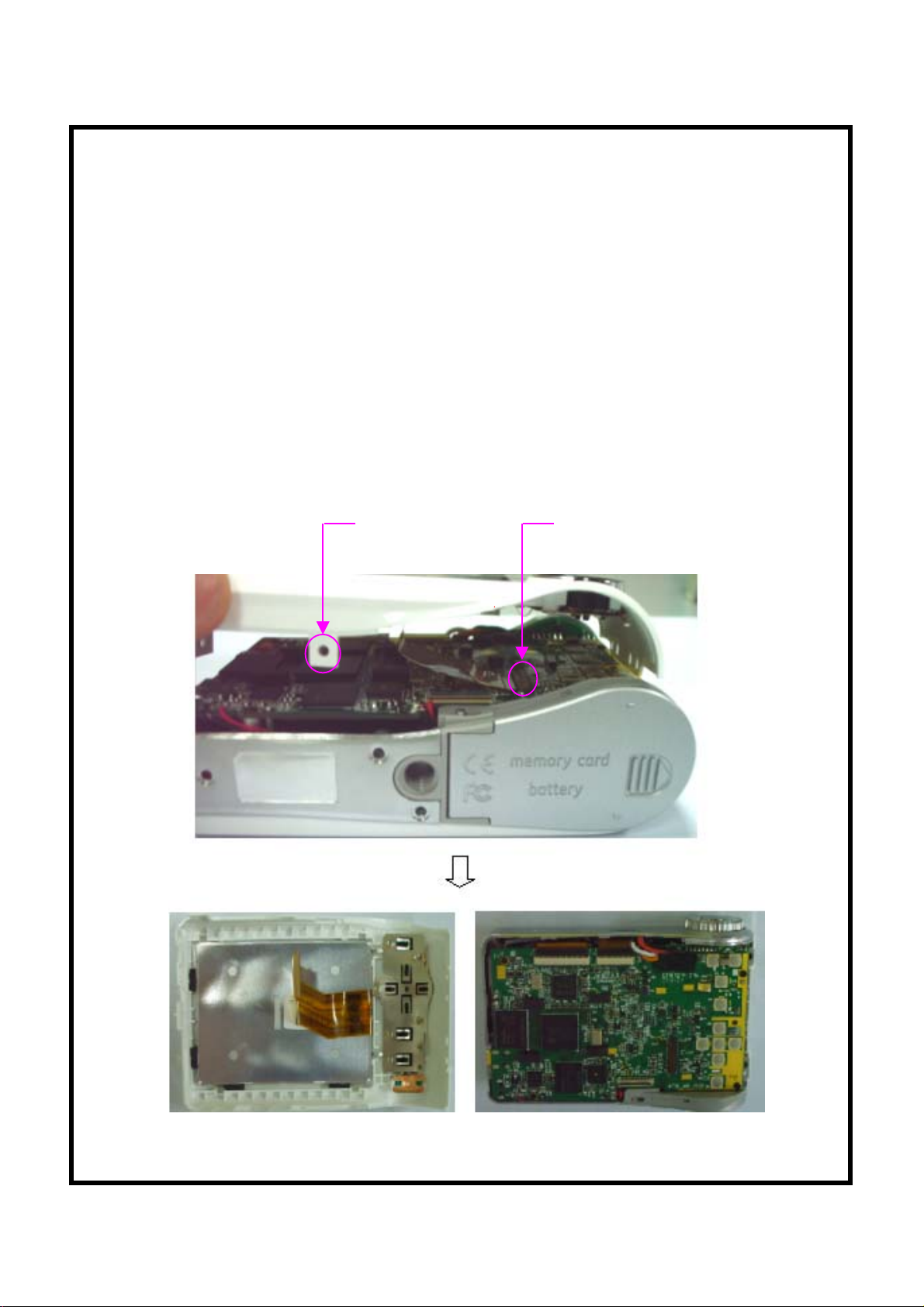
Disassemble Back Cover Unit
After the outer screws and the strap holder are removed, the back cover
unit can be disassembled.
Note: 1. While disassembling the back cover unit, be careful not to apply too much force to
avoid damage to the back cover hook(s).
2. The TFT LCD FPC is connected to the CONNECTOR on the M/B, so after the
back cover is separated from the middle cover, the connection between the LCD
FPC and the M/B can be accessed (as shown in the figure).
Hook position on
the back cover
(example)
Connection joint on
the M/B for the
LCD FPC
Page 14
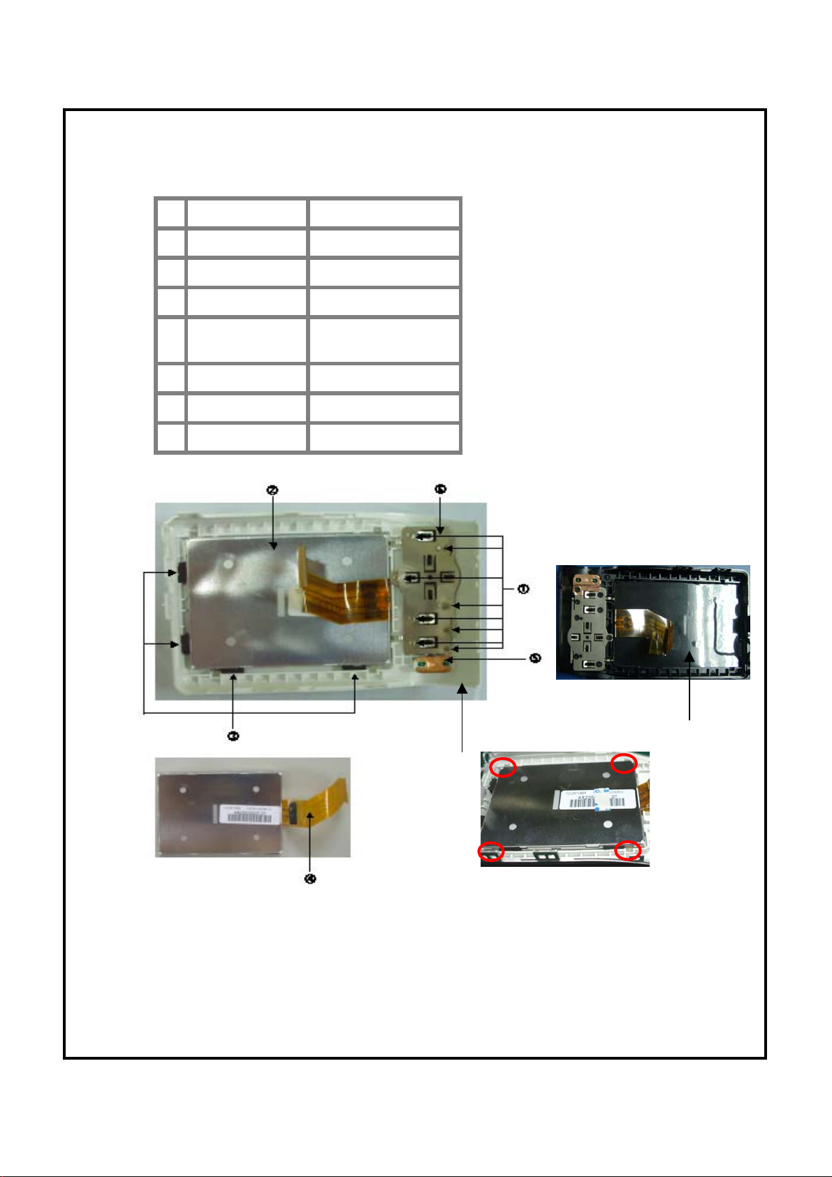
Disassemble the Back Cover Unit - 1
CR073070299
①
ELC0730009
②
CR073032399
③
CR073032699
④
CR073033099
⑤
CR073031199
⑥
CR073032799
⑦
CR073011199
⑧
Screw
LCD
LCD Sponge
LCD-FPC Tape
W/T Button AntiStatic Paste
Button Buffer
LCD Tape
LCD Insulated Pet
⑧
⑦
Figure 1
Note:
1. While assembling, attach the LCD-FPC tape on the back cover, attach the LCD
sponges on the back cover according to the 4 positions in Figure 1, assemble the
LCD and then fix it with adhesive (as shown in Figure 2).
Figure 2
Page 15

Disassemble the Back Cover Unit - 2
CR073030899
①
CR073030799
②
CR073030299
③
CR073033099
④
CR073032199
⑤
CR073031099
⑥
CR073031999
⑦
CR073031699
⑧
Direction Button Ring
Direction Button
W-T Button
W-T Button Anti- Static Paste
Delete Key (Black)
OK Key (Black)
MENU Key
Face Clear Key
Note:
1. While assembling the Face Clear key, MENU key, OK key, and the Delete key,
the thinking proof design on the back cover can avoid the assembly in the reverse
direction.
2. Assemble the direction button first and then the OK key.
3. After the 4 buttons are assembled, the back button board should be assembled
and the screws are then fastened.
Page 16

Disassemble the Back Cover Unit - 3
CR073031299 TFT Protector
①
CR073032599
②
CR073030299 W-T Button
③
CR073031699 Face Clear Key
④
CR073031999 MENU Key
⑤
CR550330499
⑥
CR073031099 OK Key (Black)
⑦
CR550335599 OK Key Cover
⑧
CR073032199 Delete Key (Black)
⑨
CR073030499 W-T Spring
⑩
TFT Protector Paste
Direction Button
Cover (Black)
Note:
1. The direction button cover and the direction button are fixed with adhesive.
2. After the direction button ring is assembled, the direction button should be assembled.
The thinking proof design can avoid the assembly in the reverse direction.
3. After the W-T button spring is assembled, press the W-T button into position.
Page 17

Disassemble the Battery Cover Unit
CR073040399 Battery Cover Shaft
①
CR510240299 Battery Cover Sheet
②
CR073040199 Battrey Cover
③
CR074161299 Screw
④
Note:
1. While taking out the battery cover shaft, open the battery cover and then place
the camera upside down to take out the battery cover shaft.
2. While assembling, assemble the battery cover sheet into the battery positioning
slot and then fasten the screws.
3. Put the battery cover into the body at the open position, insert the battery cover
shaft into the positioning hole and fix it and then close the battery cover.
Page 18

Discharge the Main Board
p
Disassemble the Main Board
EWI0730059 MC Line(+) Electrode
①
EWI0730069 MC Line(-) Electrode
②
EWI0730019 Xe Line(+) Electrode
③
CR073033799
④
Note: After the MC_PET is torn off, discharge is performed by using the discharge
rod. While discharging, the positive electrode of the discharge rod should be placed
at position ① or ③ in the following figure and the negative electode should be
laced at position②.
MC_PET
Page 19

Disassemble the Main Board - 1
CR0730001U9
①
CR0830001U9
CR073070199 Screw
②
CR073033799 MAIN PCB SPONGE
③
CR073010599 MC_PET
④
CCD FPC
⑤
CCD FPC CONECTOR
⑥
LENS FPC
⑦
LENS FPC CONECTOR
⑧
MAIN PCB UNIT
Note:
1. Before disassembling the M/B, make sure that the main capacitor has been
discharged completely.
2. While disconnecting CCD FPC and LENS FPC from the M/B, pay attention to
avoid damaging the connector on the M/B.
Page 20

Disassemble the Main Board - 2
EWI0730059
①
EWI0730069
②
EWI0730019
③
EWI0730029
④
EWI0730009
⑤
EWI0730039
⑥
EWI0730049
⑦
MIC Line(+) Electrode
⑧
MIC Line(-) Electrode
⑨
Speaker Line(+) Electrode
⑩
Speaker Line(-) Electrode
⑪
MC line(+) Electrode
MC line(-) Electrode
Xe Line(+) Electrode
Xe Line(-) Electrode
Trigger Line Electrode
AF Light Line(+) Electrode
AF Light Line(-) Electrode
a
Note: While soldering the wires, pay attention not to mix up the position or reverse
the positive/negative electrode (there are +/- marks printed on the M/B)
Page 21

Disassemble the Lens unit
CR0730601U9 LENS UNIT
①
CC039225899 SCREW
②
CCD FPC
③
LENS FPC
④
CR073011099
⑤
M/B sustained sponge
②
③④
①
②②
⑤
Note: While disassembling or assembling the lens unit, pay attention
not to damage CCD FPC and Lens FPC.
While assembling, press the lens unit into position, and then fasten the
screws.
Page 22

Disassemble the Body Unit - 1
CR073070199 Screw*5
①
Body Unit
Note:
After the Body fastening screws are removed and the Body Unit, the middle cover and the
front cover are to be diassembled, disassemble the Body Unit from the Tripod thread hole
first. Pay attention not to scratch or damage the appearance. (as shown i
Middle Cover and Front Cover Unit
Tripod Thread Hole
Page 23

Disassemble the Body Unit -2
ECA0606039
①
EBO3012049
②
EWI0730069
③
EWI0730059
④
CR011311199 Capacitor tape
⑤
Main capacitor
CAP board
MC line(-)
MC line(+)
①
③
⑤
③
②
①
④
The side printed in white is the negative electrode.
Note: The side on the Capacitor printed in white should be connected to the negative
wire by soldering.
Page 24

Disassemble the Body Unit -3
ESP3002109 Speaker
①
①
Note: While attaching the Speaker, the wires should face to the bottom side of the
Body to prevent the soldering operation being impeded due to insufficient length of
the wire.
Page 25

Disassemble the Body Unit -4
CR0730004U9 POWER PCB UNIT
①
CR073070299
②
Screw
Note:
While disassembling or assembling the POWER PCB UNIT, pay attention not to
damage the electronic parts on the POWER PCB UNIT.
Page 26

Disassemble the Body Unit -5
CR510210299 Battery Buffer(+)
①
CR510210399 Battery Buffer(-)
②
CR074161299 Screw
③
CR074150199
④
ISOLATION
PIECE (FC)
③
④
Note:
1
While disassembling or assembling the battery buffer, pay attention to avoid
defective contact due to deformation.
2
Assemble the isolation piece (FC) into the positive battery buffer.
3. After the +/- battery buffers are assembled into position, fasten the screws.
Page 27

Disassemble the Body Unit -6
⑦
EWI0730009 Xe Line(+)
①
EWI0730019 Trigger Line
②
EWI0730029 Xe Line(-)
③
CC039109499 Cu Foil
④
CR050310399 Reflector Umbrella
⑤
CR074150299 Xe Silicone
⑥
EXE3003029
⑦
Assembly:
Xe Tube
①
②
③
④
⑥
Note: The end with black core of the Xe tube
(as shown in the figure) is the negative end
for connecting the wire. It should be
identified carefully while inserting it into the
reflector umbrella and soldering the wires
(as shown in the above figure)
1. Attach the Cu Foil on the surface of the reflector umbrella, then connect the
trigger line on the Cu foil by soldering (the side of the reflector umbrella)
2. Put the Xe Silicone around the negative end of the Xe tube (black end is negative),
insert it into the reflector umbrellas, and then put it around the positive end of the Xe
tube.
3. Connect the wires (+/-) for the Xe tube on either side of the Xe tube (Orange for
positive, Brown for negative)
4. Brush the black insulation adhesive on the solder joints of the wires to cover the
solder joints.
Page 28

Disassemble the Middle Cover Unit - 1
CR073020299
①
CR073020399 Flash Panel
②
CR073070199 Screw
③
CR074161299 Screw
④
EDI3055059 AF_LED
⑤
EWI0730039 AF_LED Line(+)
⑥
EWI0730049 AF_LED Line(-)
⑦
Middle Cover
②③①④
⑦⑤⑥ ⑤
Note:
1. After the AF_LED is assembled into position, it should be fixed with
adhesive around.
Page 29

Disassemble the Middle Cover Unit - 2
After the middle cover and the fastening screws on the front cover are disassembled,
the middle cover can be separated from the front cover
Middle Cover Unit Front Cover Unit
Note: While disassembling the middle cover unit and the front cover unit,
do not apply too much force on the top joint to avoid damage on the front
cover.
Page 30

Disassemble the Middle Cover Unit - 3
CR0730002U9 TOP PCB UNIT
①
CR073070299 Screw
②
CR073020799 POWER KEY
③
Note: The power key is assembled and fixed by pressing to fit, while
disassembling or assembling, do not apply too much force on it to prevent
the frame of the power key from deforming so that the response of the
button will change.
Page 31

Disassemble the Middle Cover Unit - 4
CR073021099 Modedial Board Brush
①
CR085070299
②
CR073021299
③
CR073021199
④
Screw
Mold LED light guide
Modedial Body Board
①
②
④
③
Note:
1. While disassembling and assembling the Modedial Board Brush, it is
necessary to prevent the brush from deformation. (it must be kept at the same
level)
2. While disassembling the Modedial Body Board, pay attention to prevent the
bottom spring and the steel ball from falling out.
3. After the Modedial Body Board is assembled, fasten the screws.
4. After the Modedial Board Brush is assembled into the Modedial, it is
necessary to fasten the screw.
Page 32

Disassemble the Middle Cover Unit - 5
p
CR073021499 Modedial Spring
①
CR073021399 Mode Ball
②
CR073021299
③
CR073020899
④
Mold LED light guide
Modedial Body
①
②
④
③
Note:
1. While assembling the Spring and the Mode Ball, assemble the spring first and
then assemble the Mode ball. After that, Assemble the modedial body board into
osition, and fasten the screws.
2. After the Mold LED light guide is assembled into position, fix it with
adhesive.
Page 33

Disassemble the Middle Cover Unit --6
CR073020599
①
CR073020699
②
Shutter Button
Shutter Button Spring
①②
Shutter
Button Hook
Note:
1. While disassembling the Shutter Button, separate the Shutter Button hook from
the Modedial first. Pay attention not to apply too much force to avoid damage to the
hook.
2. While attaching the Modedial cover on the Modedial, align the small dip (between
the Motion Picture Mode Mark and the Manual Mode Mark) to the small dot on the
Modedial
3. While assembling the Shutter Button Spring, the small winding side should face to
the Modedial.
Page 34

Disassemble the Middle Cover Unit --7
CR073020899
①
CR073020999 Modedial Cover
②
CR073021799
③
Modedial Body
Modedial Cover Paste
①
Note: While assembling the Modedial Cover, the small dip on the edge should be aligned
to the small dot on the Modedial body (as the red circle shown in the above figure) and
then attach it on the Modeldial body.
②
(Attach on the back of the Modedial Cover)
③
Page 35

Disassemble the Front Cover Unit
CR007020199
CR007021599
①
CR008020199
CR008021599
EMI3003219
②
CR073020499
③
Front Cover(Black)
Front Cover(Silver)
Front Cover(Black)
Front Cover(Silver)
MIC
Self LED leader
②③①
Note: After the Self LED leader is assembled into position, it should be fixed with
adhesive around.
LOGO should be attached on the circular positioning hole on the Front Cover. Note
that the logo should not be attached slantedly.
Page 36

6. Test Station
6-1 Test Items and Procedure for Main parts while being Replaced
CCD
Bad Pixel
Compensation
Color
Calibration
Auto
Focus
Cali
Flash
Write USBIDLanguage
Setting
⑪⑫ ⑬ ⑭
Lens Unit
CCD Unit
M/B Unit
Flash Unit
Version
Update
Self
Test
Lens
Test
EFA Run In
End
Voltage
ISO
Sensitivity
Shutter
Calibration
①②③ ④ ⑤ ⑥ ⑦ ⑧⑨ ⑩
①②③ ④ ⑤ ⑥ ⑦ ⑧⑨ ⑩
①②③④⑤⑥⑦ ⑧ ⑨ ⑩
①②③
Note:1.For End Voltage Setting, the feedback type constant current source is used.
2. After replacing the M/B, each test item must be adjusted; otherwise, the “Need Cali” message will appear. (It is used as the indication in the
software control. If there is any missed operation, Red "Need Cali" message will be shown at the low
6-2 List of Measurement Instruments used for the Test
Name of the Used Instrument
Camera Holder Stage (Test Stage)
For carrying and fixing the camera.
Note
Ordinary Constant Power Supply
For providing stable power supply to the camera. (It will be used for all test items except the End Voltage Setting). It can be
substituted by a stable adapter.
Dummy Battery Simulation Fixture For End Voltage Setting
Feedback Type Constant Power
Supply
Wood Box
DC Light
S/D Card
For End Voltage Setting. With its feedback design, the voltage stability is excellent so that the End Voltage setting can be
precise.
(As shown in Figure 4-1) For Self Test, Lens Test, and EFA. (While calibrating, the distance to the CCD side of the camera is
60 cm)
For Self Test, Lens Test and EFA
Containing the menu documents
Page 37

Wood
50cm(inf) chart
60cm(normal)
600mm
Light
Camera
Camera Holder
Light
CHART
Power Line
Figure 4-1 Figure 4-2
LV-2001A
Luminance Box
Camera
Test Stage
Camera
Test Stage
5cm(micro)
40cm(micro) chart
Camera
The distance
between the lens
and the luminance
box should be less
than 1cm.
Desktop
Figure 4-3 Figure 4-4
Power Line
Page 38

Chart Sensor
Dark
Box
Power Line
Test Stage
LV-2001A Luminance Box As shown in Figure 4-4, for ISO Sensitivity, Shutter calibration, CCD Bad Pixel compensation and Color calibration.
Auto-Focus Inspection Fixture
Dark Box for flash calibration.
18% Reflection Chart
Camera
Figure 4-5
1.(As shown in Figure 4-2) For Auto Focus Range Inspeciton of the camera. For A730/A830, the micro range mode
(micro):5~40cm, the normal mode (normal):40~infinity
2.The Chart Card is shown as in Figure 4-3. For Micro mode, the line spacing in the chart i
As shown in Figure 4-5 (Dimensions: approx. 50x50x50cm)
18% reflection chart for flash calibration (Dimensions: 30x30cm)
Counter
Counter Record the number of flashes during the flash calibration.
PC
USB Cable
For writing USB ID
For writing USB ID
Page 39

6-3 Operation Procedure for each Test Item
6-3.1 Operation Procedure for Self test, Lens test, and EFA
(1) . Take the camera, open the battery box cover, insert the SD card (containing the automatic menu document for Self test), plug the
power line, and then press "Power" button to start up.
(2). As shown in the following figure, the camera will automatically execute the self-test program. For the test result, observe the lower
right corner on the LCD, if "PASS" appears, then the product is good. (If there is any fault, the camera will rema
(3). Press the Power button to shut down the camera. Unplug the power line and pick out the SD card.
6-3.2 Run- in Test
(1). Take the camera, open the battery box cover, insert the SD card (containing the automatic menu), insert the power line, and press the
"Power" button to start up. The camera will automatically execute the RUN IN test program (as shown in the followin
(2). After the RUN IN test is performed for 15 minutes, there will be flashing along with the shot in the RUN IN test. After the test is
complete, "RUN IN END" will appear on the LCD. Turn off the power and unplug the power line and SD card.
Page 40

6-3.3 End Voltage Setting
(1). Take the camera, insert the S/D Card (containing the automatic Menu for End Voltage Setting), place the camera on the camera
holder, use the 2.26V power supply, and then press the power button to start up. The camera will automatically perform th
(2). BC Voltage Specifications (AVG: 810±30 for good products, otherwise defective)
(3). Turn off the power, take out the camera and unplug the S/D Card.
6-3.4 ISO Sensitivity, Shutter Calibration, CCD Bad Pixel Compensation, Color Calibration, White Image Auto Shot (5-in-1)
(1). Take the camera, open the battery box cover, insert the SD Card (containing the automatic Menu for the 5-in-1 test), place the camera
on the camera holder, make sure that the camera lens is aimed at the Luminance Box (the distance between the lens an
(2) If NG is found during the test, the program will hint automatically. (For example: if there is a CCD Bad Pixel defect, the LCD will show
BAD PIXEL: FAIL)
(3). Turn off the power, take out the camera, and unplug the S/D card.
(4) Note: The luminance and the color temperature must meet the requirements (Luminance:950±50cd/㎡; Color Temperature:3150±50K)
Page 41

6-3.5 Auto Focus Inspection
(1) Take the camera, insert the SD card (containing the automatic Menu), place the camera on the camera holder and then turn on the
power. The auto focus fixture will perform the test for 4 different distances to the Chart.
Note: (Auto Focus fixture can align the camera to the chart card by using the rotation of the motor through the electronic circuit control)
(2) If there is no Auto Focus Fixture, the following substitution method can be adopted:
Step 1: Take the camera, insert the SD card (containing the automatic Menu for Auto Focus), place the camera on the camera holder and
then turn on the power. Perform the Auto Focus at a distance of 0.6 meter to the object.
Step 2: After “FOCUS PASS” is shown, shut off machine and take out SD Card. Turn on the power again, and perform the same test for the
distances of 5cm, 40cm, and 60cm at vertical stripe Chart and infinity (it can also be focused at an object at an infini
Note:
There are two reasons for the above-said action: 1. Perform the Auto Focus inspection at different distances; 2. If the Auto Focus Test is not
performed, the "Need Cali" will not disappear)
For 5cm Chart, the mode should be Wide&Micro;
For 40cm Chart, the mode should be Tele&Micro;
For 60cm Chart, the mode should be □Wide&Normal □Tele&Norma;
For Infinity, the mode should be □Wide&Normal □Tele&Norma;
Page 42

6-3.6 Flash Calibration Operation (Cali Flash)
l
(1) . Take the camera, open the battery box cover, insert the SD card (containing the automatic Menu for Cali Flash), plug the power line,
switch the camera mode into manual mode, place the camera on the camera holder and fix it, make sure that the counte
(2). The camera will automatically execute the self-test program, the reading on the counter will change from 0 to 12 continuously, which
means that it has flashed 12 times. The camera will then automatically show the message: GO FOR REDEYE. At this m
Observe the LCD, FAIL:NG PASS: OK
(3). After Shutter calibration is “OK”, the Amplifier of the Camera will send out four times of warning sound. (for the anti-vibration
inspection as shown in the following figure). After the result is OK, turn off the power, and take out the SD card.
6-3.7 USB ID Writing Operation
(1) Insert the SD card (containing USB ID automatic Menu) plug the power line plug the USB cable and the camera wil
start up automatically.
(2) Double click on the application program
(3) Enter the serial number of the camera in the pop-up dialog (Arbitrary 10 characters), and then click OK.
(4) Retrieve the USB unplug the USB cable and the entered serial number will automatically be shown on the LCD and the camera
will automatically shut down. The USB ID writing operation is complete.
Page 43

r
t
g
o
r
Double Click
Enter the
S/N
Click
OK
Note: If the operation is not successfully completed, the following message will appea
1
2
3
4
5
6
If "Self Test; Lens Test; EFA; USB ID" is displayed, it implies the operations for Self Test, Lens Test and EFA are missed o
there is test FAIL during the three test items.
If "RUN IN; USB ID" is displayed, it implies that the operation for RUN IN test is missed or there is test FAIL during RUN IN test.
If "BC VOLTAGE; USB ID" is displayed, it implies that the operation for BC voltage setting is missed or there is test FAIL during BC vol
If "Shutter; ISO; Bad Pixel; Color; USB ID" is displayed, it implies that the operations for 5-in-1 tests are missed or there is test FAIL durin
If "AUTO FOCUS; USB ID" is displayed, it implies that the operation for Auto Focus test is missed or there is test FAIL during the Auto F
If "CALI FLASH/GYRO; USB ID" is displayed, it implies that the operation for the calibration is missed or there is a test FAIL
during the Flash flash Calibration/Anti-Vibration test.
7 For the camera that has successfully passed the USB ID writing operation, the message "NEED CALI" will automatically disappear.
Page 44

7. Circuit Diagram
7.1 Precautions
7.1.1 Notes on the Replacement of Main Board
1>.
2>.
1. After removing the Rear Cover and Lens Press Board, bleed the current of
Main Capacitor to prevent the Capacitor from discharging current to human
body.
While assembling the main board, it is necessary to fasten all the screws on the
main board and then connect it with the top cover by soldering. If the screws are
fastened after the Top cover is soldered, the copper foil on the main board will
fall off.
7.1.2 Procedures for Turning on the Instruments
1 Turn on the power (Power key on /USB on)
2 The MSP430 operation starts (PWR_ENB output signal is transmitted)
3 Turn on the three sets of voltage sources 1.3 V → 1.8 V → 3.3V
4 The MSP430 transmits SYS_RST output signal, DM350 operation starts
5 The start-up screen appears and the lens starts running.
→ Make sure that the LCD can display correctly (verify the start-up screen).
→ Make sure that the output of the CCD is correct (picture image is correct).
Page 45

DP710/DP810 BOM Table of the Unit
Model No.NO
1 CR073010199 Frame 1
2 CR510210399 Battery Buffer(+) 1
3 CR510210499 Battery Buffer(-) 1
4 CR074150199 ISOLATION PIECE(FC) 1
5 CR074150299 Xe silicone 1
6 CR011311199 Capacitor tape 1
7 CR050310399 Reflect umbrella 1
8 CR073010599 MC_PET 2
9 CR073010799 ESD sheet 1
10 CR073011199 Lcd insulated 1
11 CR073011099 M/b sustained Pet 1
11 CR007020199 front Cover(Silver) 1
12 CR007021599 front Cover(Black) 1
14 CR008020199
15 CR008021599
18 CR073020399 Flash panel 1
19 CR073020499 Self LED leader 1
20 CR073030299 W-T button 1
21 CR073030499 W-T SPRING 2
22 CR073030699 strap holder 1
23 CR073030199
24 CR073030399
26 CR073030199
27 CR073030399
30 CR073030799 Direction Button Body 1
31 CR073030899 Direction Button Holder 1
32 CR550330499 Direction Button Cover (Black) 1
33 CR073031199 Button Buffer 1
34 CR073031299 TFT protector 1
35 CR073032599 TFT protector tape 1
36 CR550335599 OK KEY COVER 1
37 CR073031099 ok key(Black) 1
38 CR073031999 menu key(Black) 1
39 CR073032199 delete key(Black) 1
40 CR073031699 face clear key(Black) 1
41 CR073032399 sponge 8
42 CR073032699 FPC tape 1
43 CR073032799 LCD tape 1
44 CR073033099 W/T PET 1
front Cover(Silver)
front Cover(Black)
Back Cover (Silver)
Back Cover (Black)
Back Cover (Silver)
Back Cover (Black)
English Name
Number of
Parts
Note
1
1
1
1
1
1
Page 46

45 CR073033799 MAIN PCB SPONGE 1
46 CR073040199 battery cover 1
47 CR510240299 battery cover sheet 1
48 CR073040399 battery Cover Shaft 1
49 CR073020299 Middle cover 1
50 CR073020599 Shutter Button 1
51 CR073020799 POWER KEY 1
52 CR073020699 Shutter Key Spring 1
53 CR073020899 Modedial Body 1
54 CR073020999 Modedial Cover 1
55 CR073021799 Modedial Cover Paste 1
56 CR073021099 Modedial Board Brush 1
57 CR073021199 Modedial Body Board 1
58 CR073021299 Mold LED light guide 1
59 CR073021399 Mode ball 1
60 CR073021499 Modedial spring 1
61 EDI3055059 AF_LED 1
62 CR073022199 LED sponge 1
63 CR073033699 POWER PCB PORON 1
64 CR073033399 ESD Cu foil 1
65 CR073033899 Middle cover tape 1
66 CC039225899 screw 3
67 CR074161399 Outer Screw 6
68 CR075760599 screw 3
69 CR073070299 screw 8
70 CR085070299 screw 2
71 CR073070199 screw 10
72 CR074161299 screw 4
73 EWI0730009 trigger line 1
74 EWI0730019 Xe line(+) 1
75 EWI0730029 Xe line(-) 1
76 EWI0730039 LED line(+) 1
77 EWI0730049 LED line(-) 1
78 EWI0730059 MC line(+) 1
79 EWI0730069 MC line(-) 1
80 EXE3003029 Xe tube 1
81 CC039109499 Cu foil 1
82 ECA0606039 main capacitor 1
83 EBO3012049 CAP board 1
84 EMI3003219 MIC 1
85 ESP3002109 SPEAKER 1
86 ELC0730009 LCD 1
87 CR0730001U9 MAIN PCB UNIT 1
88 CR0730002U9 TOP PCB UNIT 1
89 CR0730004U9 POWER PCB UNIT 1
90 CR0730601U9 LENS UNIT 1
91 CR073033999 Battery CON PORON 2
 Loading...