

Page 1
© 2003 by B&B Electronics. All rights reserved.
www.bb-elec.com orders@bb-elec.com support@bb-elec.com
International Office: 707 Dayton Road PO Box 1040 Ottawa, IL 61350 USA 815-433-5100 Fax 433-5104
European Office: Westlink Commercial Park Oranmore Co. Galway Ireland +353 91 792444 Fax +353 91 792445
PRODUCT INFORMATION B&B ELECTRONICS
485PTBR-0812-1/2
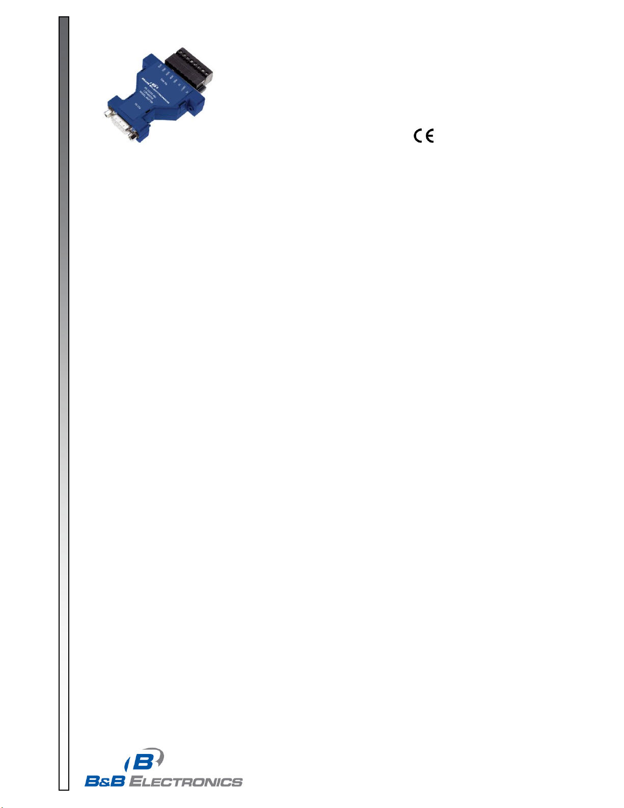
Model: 485PTBR
RS-232 to RS-485 Converter
Description
The 485PTBR converts unbalanced RS-232 signals to balanced, full or half-duplex RS-485 signals. RS-485 is an
enhanced version of the RS-422 Standard. It allows multiple drivers and receivers on a two-wire system. The RS-232
port has a female DB-9 connector with pins 2(RD), 3(TD), and 5(SG) supported. Pins 7(RTS) and 8(CTS) are tied
together. Also pins 6(DSR), 1(CD), and 4(DTR) are tied together, but not passed through the converter. The RS-485
port has an 8-position pluggable terminal block connector.
Baud Rate
The 485PTBR can accept baud rates from 300 baud to 115.2K baud. In order to change the baud rate on the 485PTBR
a resistor and possibly a capacitor must be changed. By looking up the selected baud rate on Table 1 the resistor and
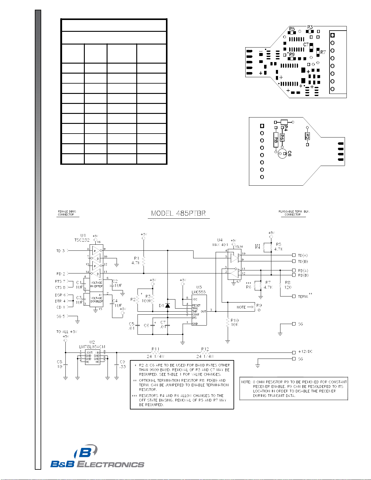
capacitor value can be determined. Remove R3 and C7 from the printed circuit board. Place new components in the R2
and C6 locations. See Figure 1 and 2 for resistor and capacitor locations.
Biasing Resistors
The biasing resistors R5 and R7 can also be altered. The 485PTBR comes standard with 4.7K biasing resistors. To
change the value of biasing resistors, remove R5 and R7 and replace with new value in locations R4 and R6. See
Figure 1 and 2 for resistor locations.
Termination Resistor
The termination resistor location for the 485PTBR is located at R8. A termination resistor can be placed in the R8
location and a jumper wire placed from the terminal location to RD(B). We recommend a value of 100 to 120 ohm
resistor for termination. See Figure 2 for termination resistor location.
Constant Receiver Enable
The 485PTBR is standard setup with the receiver disabled during transmission. The 485PTBR can be set up for
constant receiver enable. When R9 is removed the receiver is in constant receive mode (four-wire). When R9 is in the
circuit the 485PTBR is in half-duplex mode (two-wire). See Figure 1 for jumper location.
Data Line Polarity
The polarity of the two RS-485 lines must be correct. With no data being sent, the RS-232 line should be negative and
the RS-485 “A” terminal should be negative with respect to the “B” terminal. If your equipment uses a “+” and “-“ naming
scheme, in most cases the “A” line will be connected to the “-“ and the “B” line will be connected to the “+”.
Page 2
© 2003 by B&B Electronics. All rights reserved.
www.bb-elec.com orders@bb-elec.com support@bb-elec.com
International Office: 707 Dayton Road PO Box 1040 Ottawa, IL 61350 USA 815-433-5100 Fax 433-5104
European Office: Westlink Commercial Park Oranmore Co. Galway Ireland +353 91 792444 Fax +353 91 792445
PRODUCT INFORMATION B&B ELECTRONICS
Table 1
COMPONENT REPLACEMENTS FOR
CHANGING BAUD RATE TIMEOUTS
Baud
Rate
Time
(ms)
Resistor
(R3)
(ohm)
Capacitor
(C7)
(mfd)
300 33.3 330K 0.1
600 16.6 160K 0.1
1200 8.33 820K 0.01
2400 4.16 430K 0.01
4800 2.08 200K 0.01
9600 1.04 100K 0.01
19200 .520 56K 0.01
38400 .260 27K 0.01
57600 .176 16K 0.01
115200 .0868 8.2K 0.01
Figure 1. PC Board Layout - Top
Figure 2. PC Board Layout - Bottom
485PTBR-0812-2/2
 Loading...