


Multi-Interface PCI Bus Serial Cards
(RS-232 / RS-422 / RS-485)
Models 3PCIU2, 3PCIU4, 3PCIU8
(Non-Isolated) and
Models 3PCIOU1, 3PCIOU2, 3PCIOU4
(Isolated)
Manual Documentation Number 3PCIoUx-1008

International Headquarters
B&B Electronics Mfg. Co. Inc.
707 Dayton Road
Ottawa, IL 61350 USA
Phone (815) 433-5100 -- General Fax (815) 433-5105
Website: www.bb-elec.com
Sales e-mail: orders@bb-elec.com -- Fax (815) 433-5109
Technical Support e-mail: support@bb.elec.com -- Fax (815) 433-5104
European Headquarters
B&B Electronics
Westlink Commercial Park
Oranmore, Co. Galway, Ireland
Phone +353 91-792444 -- Fax +353 91-792445
Website: www.bb-europe.com
Sales e-mail: sales@bb-europe.com
Technical Support e-mail: support@bb-europe.com
© 2008 B&B Electronics – Revised February 2008
Manual Documentation Number 3PCIoUx-1008
B&B Electronics Mfg Co Inc – 707 Dayton Rd - PO Box 1040 - Ottawa IL 61350 - Ph 815-433-5100 - Fax 815-433-5104 – www.bb-elec.com B&B Electronics Ltd – Westlink Commercial Park – Oranmore, Galway, Ireland – Ph +353 91-792444 – Fax +353 91-792445 – www.bb-europe.com

CAUTION:
This is an Electrostatic Sensitive Device. Use ESD precautions for safe handling.
Before removing the card from the anti-static protective packaging:
- Discharge any static electricity buildup on your body by touching a large grounded metal surface or the metal chassis on equipment connected to earth ground by a 3-wire power cord. Use of a grounding wrist strap is recommended.
-Avoid touching the gold connectors or other parts on the card except when necessary to set the configuration DIP switches.
-Remove AC power from the computer before inserting the card
© 2008 B&B Electronics. No part of this publication may be reproduced or transmitted in any form or by any means, electronic or
mechanical, including photography, recording, or any information storage and retrieval system without written consent. Information in this manual is subject to change without notice, and does not represent a commitment on the part of B&B Electronics.
B&B Electronics shall not be liable for incidental or consequential damages resulting from the furnishing, performance, or use of this manual.
All brand names used in this manual are the registered trademarks of their respective owners. The use of trademarks or other designations in this publication is for reference purposes only and does not constitute an endorsement by the trademark holder.
Manual Documentation Number 3PCIoUx-1008 |
Table of Contents |
i |

|
|
Table of Contents |
|
TABLE OF CONTENTS ........................................................................................... |
|
II |
|
CHAPTER 1: GENERAL INFORMATION |
........................................................... |
1 |
|
|
INTRODUCTION ........................................................................................................... |
|
1 |
|
FEATURES................................................................................................................... |
|
1 |
|
MIPORT MODELS AND FEATURES............................................................................... |
|
3 |
|
QUICK START GUIDE .................................................................................................. |
|
5 |
|
SPECIFICATIONS.......................................................................................................... |
|
7 |
CHAPTER 2: SERIAL CARD SETUP..................................................................... |
|
8 |
|
|
PRE-SETUP STEPS ....................................................................................................... |
|
8 |
|
ESD Precautions.................................................................................................... |
|
8 |
|
Initial Configuration .............................................................................................. |
|
8 |
|
OVERVIEW OF OPERATIONAL MODES......................................................................... |
|
9 |
|
RS-232 Mode.......................................................................................................... |
|
9 |
|
RS-422 Mode.......................................................................................................... |
|
9 |
|
RS-485 Mode.......................................................................................................... |
|
9 |
|
OPERATING MODE SELECTION ................................................................................. |
|
10 |
|
Setting the DIP Switches on RS-232/422/485 Ports............................................. |
11 |
|
|
Setting the DIP Switches on RS-422/485 Only Ports........................................... |
12 |
|
|
INSTALLING THE SERIAL CARD................................................................................. |
|
14 |
CHAPTER 3: DRIVER SOFTWARE INSTALLATION...................................... |
15 |
||
|
INSTALLING WINDOWS VISTA DRIVER SOFTWARE................................................... |
15 |
|
|
Pre-Installation Steps........................................................................................... |
|
15 |
|
Using the Found New Hardware Wizard............................................................. |
|
16 |
|
INSTALLING WINDOWS XP PROFESSIONAL DRIVER SOFTWARE ............................... |
17 |
|
|
Windows Settings ................................................................................................. |
|
17 |
|
Pre-Installation Steps........................................................................................... |
|
17 |
|
Using the Found New Hardware Wizard............................................................. |
|
18 |
|
Checking the Driver Installation.......................................................................... |
|
20 |
|
INSTALLING WINDOWS 2000 PROFESSIONAL DRIVER SOFTWARE ............................ |
22 |
|
|
Windows Settings ................................................................................................. |
|
22 |
|
Pre-Installation Steps........................................................................................... |
|
22 |
|
Using the Found New Hardware Wizard............................................................. |
|
23 |
|
Checking the Driver Installation.......................................................................... |
|
27 |
|
INSTALLING WINDOWS 98 OR ME DRIVER SOFTWARE............................................. |
28 |
|
|
Windows Settings ................................................................................................. |
|
28 |
|
Pre-Installation Steps........................................................................................... |
|
28 |
|
Using the Add New Hardware Wizard................................................................. |
|
29 |
|
Checking the Driver Installation.......................................................................... |
|
32 |
ii |
Table of Contents |
Manual Documentation Number 3PCIoUx-1008 |
|

INSTALLING WINDOWS NT DRIVER SOFTWARE ....................................................... |
|
34 |
INSTALLING WINDOWS NT DRIVER SOFTWARE ....................................................... |
|
34 |
Windows Settings ................................................................................................. |
|
34 |
Pre-Installation Steps........................................................................................... |
|
34 |
Installing the Driver Software.............................................................................. |
|
34 |
Configuring the Serial Ports ................................................................................ |
|
37 |
CHAPTER 4: SETTING DRIVER OPTIONS ....................................................... |
|
40 |
CONFIGURING PORT SETTINGS (DOES NOT APPLY TO WINDOWS NT.) ..................... |
40 |
|
SETTING THE FIFO BUFFERS .................................................................................... |
|
41 |
SETTING THE RTS CONTROL PARAMETER................................................................ |
|
42 |
SETTING THE HARDWARE HANDSHAKING LEVEL..................................................... |
|
42 |
CHANGING THE COM PORT NAME/NUMBER............................................................ |
|
42 |
CHAPTER 5: INSTALLING LINUX DRIVER SOFTWARE ............................. |
44 |
|
INSTALLING MIPORT DRIVERS IN LINUX .................................................................. |
|
44 |
Preparing the Linux Files .................................................................................... |
|
44 |
Compiling the Driver ........................................................................................... |
|
44 |
Installing the Driver............................................................................................. |
|
45 |
CHECKING THE DRIVER INSTALLATION .................................................................... |
|
47 |
USING THE EXAR SERIAL GUI EXAMPLE APPLICATION ........................................... |
48 |
|
Preparing the Example Application Files............................................................ |
|
48 |
Running the Exar Serial Test GUI ....................................................................... |
|
48 |
Configuring Port Settings .................................................................................... |
|
50 |
CHAPTER 6: REMOVING DRIVERS, PORTS AND CARDS............................ |
51 |
|
REMOVING MIPORT CARDS FROM WIN98/ME/2000/2003 SERVER/XP/VISTA......... |
51 |
|
Uninstalling the MIport Card .............................................................................. |
|
51 |
Uninstalling the COM ports................................................................................. |
|
51 |
Removing INF and PNF Driver Files .................................................................. |
|
52 |
REMOVING MIPORT CARDS FROM WINDOWS NT..................................................... |
|
54 |
Uninstalling the MIport Card .............................................................................. |
|
54 |
Uninstalling the Driver ........................................................................................ |
|
54 |
CHAPTER 7: RS-232 CONNECTIONS/OPERATION......................................... |
55 |
|
RS-232 MODE .......................................................................................................... |
|
55 |
RS-232 SIGNAL DESIGNATIONS AND DB-9 PINOUT ................................................. |
|
55 |
RS-232 Signal Designations................................................................................. |
|
56 |
DTE AND DCE ......................................................................................................... |
|
56 |
RS-232 SIGNAL LEVELS ........................................................................................... |
|
57 |
HANDSHAKING ......................................................................................................... |
|
57 |
RTS CONTROL IN RS-232 MODE ............................................................................. |
|
57 |
CHAPTER 8: RS-422/485 CONNECTIONS/OPERATION ................................. |
59 |
|
RS-422/485 MODE ................................................................................................... |
|
59 |
Manual Documentation Number 3PCIoUx-1008 |
Table of Contents |
iii |

RS-422/485 SIGNAL DESIGNATIONS AND DB-9 PINOUT .......................................... |
59 |
RS-422/485 Signal Designations ......................................................................... |
60 |
RS-422/485 DIFFERENTIAL SIGNALS........................................................................ |
60 |
RS-422 OPERATION.................................................................................................. |
61 |
RS-422 Limitations............................................................................................... |
61 |
RS-485 OPERATION.................................................................................................. |
61 |
Send Data Control ............................................................................................... |
62 |
RS-485 TERMINATION RESISTORS............................................................................ |
63 |
RS-485 NETWORK BIASING...................................................................................... |
63 |
2-WIRE RS-485 CONNECTIONS ................................................................................ |
65 |
2-Wire RS-485 Mode: .......................................................................................... |
65 |
4-WIRE RS-422 AND RS-485 CONNECTIONS............................................................ |
65 |
RS-422 Point to Point Connection ....................................................................... |
65 |
RS-422 Point to Multipoints Connection ............................................................. |
66 |
4-Wire RS-485 Connection .................................................................................. |
66 |
CHAPTER 9: TROUBLESHOOTING MIPORT CARDS.................................... |
68 |
STARTING UP............................................................................................................ |
68 |
CHECKING CONNECTIONS......................................................................................... |
68 |
RS-232/422/485 Operation .................................................................................. |
68 |
RS-232 Operation ................................................................................................ |
68 |
RS-422/485 Operation ......................................................................................... |
69 |
CHECKING THE MIPORT CARD ................................................................................. |
69 |
Support................................................................................................................. |
71 |
APPENDIX A: DIP SWITCH/MODE SETTINGS .................................................. |
1 |
SETTING THE DIP SWITCHES ON RS-232/422/485 PORTS........................................... |
1 |
DIP Switch 1 (RS-232/422/485 ports).................................................................... |
1 |
DIP Switch 2 (RS-232/422/485 ports).................................................................... |
1 |
DIP Switch 3 (RS-232/422/485 ports).................................................................... |
2 |
SETTING THE DIP SWITCHES ON RS-422/485 ONLY PORTS........................................ |
2 |
APPENDIX B: CONNECTOR PINOUTS ............................................................... |
1 |
RS-232 PINOUTS ........................................................................................................ |
1 |
RS-422/485 PINOUTS ................................................................................................. |
2 |
APPENDIX C: TROUBLESHOOTING WITH COMTEST ................................. |
1 |
COMTEST FEATURES .................................................................................................. |
1 |
INSTALLING COMTEST ............................................................................................... |
2 |
LOOPBACK TESTING WITH COMTEST ......................................................................... |
2 |
APPENDIX D: DECLARATION OF CONFORMITY STATEMENT ................ |
5 |
iv |
Table of Contents |
Manual Documentation Number 3PCIoUx-1008 |
General Information
Chapter 1: General Information
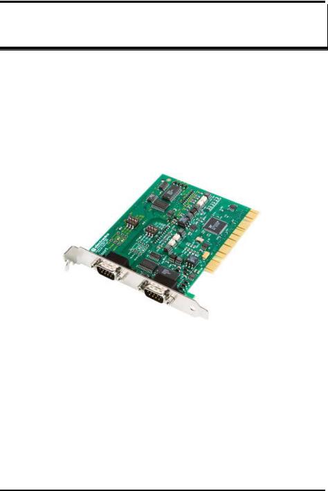
Introduction
MIport PCI serial interface cards allow you to add RS-232, RS-422 and RS485 interfaces to Windows based computers equipped with a PCI bus. Depending on your choice of card one, two or four optically isolated serial ports, or two, four or eight non-isolated serial ports, can be added. MIport PCI serial cards are Plug and Play compatible, which allows the Windows Operating System and driver to set the addresses and IRQ used by the card.
Figure 1. A 3PCIOU2 Optically Isolated Two-Port PCI Serial
Interface Card
Features
•Optically isolated or non-isolated models available
•Isolated models available in 1, 2 or 4 ports
•Non-isolated models available in 2, 4 or 8 ports
•4 and 8 port models include fanout cables
•Plug & Play compatible – Windows sets addresses and IRQ used
•5 volt and 3.3 volt PCI bus compatible
•PCI-X compatible
Manual Documentation Number 3PCIoUx-1008 |
Chapter 1 |
1 |

General Information
•Conform to the PCI V2.3 Universal PCI specification
•RS-232/RS-422/RS-485 interfaces
•2-wire or 4-wire RS-485 operation (half or full-duplex)
•Automatic Send Data Control for RS-485 operation
•Buffered high speed XR17D15x PCI Bus UARTs (16C550 compatible) with 64 byte FIFOs for input/output with programmable trigger thresholds
•Advanced driver function for COM port rename (Refer to Chapter 4)
•Supports baud rates up to 460.8 kbps
•Windows 98, ME, NT4.0, 2000, 2003 Server, XP, Vista and Linux 2.4 supported
2 |
Chapter 1 |
Manual Documentation Number 3PCIoUx-1008 |

General Information
MIport Models and Features
|
Model |
Ports |
Interface |
Connectors |
|
|
|
Number |
|
|
|
|
|
|
3PCIOU1 |
1 |
RS-232/422/485 |
DB-9 male |
|
|
|
|
|
|
|
|
|
|
3PCIOU2 |
2 |
RS-232/422/485 |
DB-9 male |
|
|
|
|
|
|
|
|
|
|
3PCIOU4 |
4 |
2 RS-232/422/485 ports |
2 x DB-9 male |
|
|
|
|
|
2 RS-422/485 ports |
2 x DB-9 male use 2nd expansion |
|
|
|
|
|
|
slot |
|
|
|
|
|
|
|
|
|
|
|
Figure 2. MIport Optically Isolated PCI Cards |
|
|
||
|
|
|
|
|
|
|
Manual Documentation Number 3PCIoUx-1008 |
Chapter 1 |
3 |
|
|||

General Information
|
Model |
Ports |
Interface |
Connectors |
|
|
Number |
|
|
|
|
|
3PCIU2 |
2 |
RS-232/422/485 |
2 x DB-9 male |
|
|
|
|
|
|
|
|
3PCIU4 |
4 |
RS-232/422/485 |
DB-37 female |
|
|
|
|
|
(plus DB-37 to 4x DB-9 male |
|
|
|
|
|
cable) |
|
|
|
|
|
|
|
|
3PCIU8 |
8 |
4 RS-232/422/485 ports |
DB-78 female |
|
|
|
|
4 RS-232 ports |
(plus DB-78 to 8x DB-9 male |
|
|
|
|
|
cable) |
|
|
|
|
|
|
|
|
|
Figure 3. MIport Non-Isolated PCI Cards |
|
||
|
|
|
|
|
|
4 |
|
Chapter 1 |
Manual Documentation Number 3PCIoUx-1008 |
|
|
General Information
Quick Start Guide
CAUTION:
This is an Electrostatic Sensitive Device. Use ESD precautions for safe handling.
Before removing the card from the anti-static protective packaging:
- Discharge any static electricity buildup on your body by touching a large grounded metal surface or the metal chassis on equipment connected to earth ground by a 3-wire power cord. Use of a grounding wrist strap is recommended.
-Avoid touching the gold connectors or other parts on the card except when necessary to set the configuration DIP switches.
-Remove AC power from the computer before inserting the card
1.Determine the interface requirements of your application, including:
a.Interface standard(s) (RS-232, RS-422 or RS-485)
b.Data transmission mode (Two-wire or four-wire)
c.Cable lengths, connectors, pinouts
Note: For information on cables and pinouts refer to Chapter 5 (RS-
232)or Chapter 6 (RS-422/RS-485).
2.Set the operating mode DIP switches to configure the communications interface for the required interface standard and transmit/receive mode.
Note: Refer to the DIP switch table in Chapter 2.
3.Shut down your computer. (You may want to unplug the computer power cord to prevent accidentally turning the computer on during installation.)
4.Install the PCI card in your computer and replace the cover.
5.Connect the cable(s) from the card to your peripheral device (Cable also can be connected/changed later.)
6.Power up the computer
7.Insert the driver disc into your CD-ROM drive
8.Wait until new hardware is detected.
9.Follow the instructions in the Add New Hardware Wizard. (This varies depending on your operating system.)
Note: Refer to Chapter 3.
10. Check for new COM ports in Device Manager.
Manual Documentation Number 3PCIoUx-1008 |
Chapter 1 |
5 |

General Information
11.Select the appropriate COM port, double-click and check properties.
12.Check and set up Port Settings
13.Under Advanced Settings, set Buffer, RTS Control and Hysteresis Level. Change the COM port name, if necessary.
14.If your card was not connected to a peripheral device in Step 5, make your connections now. (Powering down the computer while making connections is recommended.)
15.Use a communications test program (such as ComTest) to check communications between the computer and your peripheral device.
6 |
Chapter 1 |
Manual Documentation Number 3PCIoUx-1008 |
|
|
|
|
General Information |
|
|
|
Specifications |
|
|
|
|
|
|
|
|
|
|
||
|
OS Supported |
Windows 98, ME, NT 4.0, 2000, 2003 Server, XP, Vista and Linux 2.4 |
|
|
||
|
Bus |
PCI bus (33MHz/32-bit) PCI Bus specification |
|
|
||
|
Slot |
Requires one PCI slot (3.3V or 5V signaling) |
|
|
||
|
Baud Rates |
Maximum: |
Up to 460.8 kbps (RS-232/422/485) |
|
|
|
|
|
Typical: |
75, 110, 134, 150, 300, 600, 1200, 1800, 2400, 4800, |
|
||
|
|
|
7200, 9600, 14.4k, 19.2k, 38.4k, 57.6k, 115.2k, |
|
|
|
|
|
|
230.4k, 460.8k |
|
|
|
|
UARTs |
XR17D15x (16C550 compatible) with 64 byte FIFO buffers |
|
|
||
|
Character Length |
5, 6, 7 or 8 bits |
|
|
|
|
|
Parity |
Even, odd, none, space or mark |
|
|
|
|
|
Stop Bits |
1, 1.5 or 2 |
|
|
|
|
|
Optical Isolation |
2000 VDC minimum on all lines |
|
|
|
|
|
(3PCIOU1, |
Ports are isolated from the PC power and ground, as well as other ports |
|
|
||
|
3PCIOU2, |
on the same card. |
|
|
|
|
|
3PCIOU4 only) |
|
|
|
|
|
|
|
|
|
|
|
|
|
Connectors |
3PCIOU1: |
1 – DB-9 male |
|
|
|
|
|
3PCIOU2: |
2 – DB-9 male |
|
|
|
|
|
3PCIOU4: |
2 – DB-9 male (RS-232/422/485 ports) |
|
|
|
|
|
|
2 – DB-9 male via ribbon cable on 2nd expansion slot |
|
||
|
|
|
bracket (RS-422/485 ports) |
|
|
|
|
|
3PCIU2: |
2 – DB-9 male |
|
|
|
|
|
3PCIU4: |
1 – DB-37 female with DB-37 to 4 x DB-9 male |
|
|
|
|
|
|
cable |
|
|
|
|
|
3PCIU8: |
1 - DB-78 female with DB-78 to 8 x DB-9 male |
|
|
|
|
|
|
cable (4 x RS-232/422/485 and 4 x RS-232) |
|
|
|
|
Data Signals |
RS-232: |
TD, RD, RTS, CTS, DTR, DSR, DCD, RI and GND |
|
||
|
|
|
(TD, RD, RTS, CTS, GND only on 3PCIOU4) |
|
|
|
|
|
RS-422: |
TD(A)-, TD(B)+, RD(A)-, RD(B)+ and GND |
|
|
|
|
|
RS-485: |
Data(A)-, Data(B)+ and GND |
|
|
|
|
Environmental |
Operating temperature range: 0º to 50ºC minimum |
|
|
||
|
|
Operating humidity: 5% to 95%, non-condensing |
|
|
||
|
Dimensions |
4.8 x 3.8 in (12.2 x 9.6 cm) card edge |
|
|
|
|
|
|
(Mounting bracket, 1.2 x 12.1 x 0.9 cm) |
|
|
|
|
|
Accessories |
Software: |
Driver CD-ROM disc for Windows 98, ME, NT, |
|
|
|
|
|
|
4.0, 2000, 2003 Server, XP, Vista, and Linux 2.4 |
|
|
|
|
|
Manual: |
Instruction Manual Contained on CD ROM |
|
|
|
|
|
Figure 4. MIport Serial Card Specifications |
|
|
||
|
|
|
|
|
|
|
|
Manual Documentation Number 3PCIoUx-1008 |
Chapter 1 |
7 |
|
||

Serial Card Setup
Chapter 2: Serial Card Setup
The following Serial Card Setup section applies to the following PCI cards:
•3PCIOU1 one port optically isolated PCI serial card
•3PCIOU2 two port optically isolated PCI serial card
•3PCIOU4 four port optically isolated PCI serial card
•3PCIU2 two port non-isolated PCI serial card
•3PCIU4 four port non-isolated PCI serial card
•3PCIU8 eight port non-isolated PCI serial card
Any deviations from the procedure for specific models are noted.
Pre-Setup Steps
Your serial card has been tested for proper operation before packaging and shipping. It should be in perfect mechanical and electrical condition upon receipt.
ESD Precautions
To ensure a successful installation and setup it is important that you follow the standard ESD precautions outlined below:
CAUTION:
This is an Electrostatic Sensitive Device. Use ESD precautions for safe handling.
Before removing the card from the anti-static protective packaging:
- Discharge any static electricity buildup on your body by touching a large grounded metal surface or the metal chassis on equipment connected to earth ground by a 3-wire power cord. Use of a grounding wrist strap is recommended.
-Avoid touching the gold connectors or other parts on the card except when necessary to set the configuration DIP switches.
-Remove AC power from the computer before inserting the card
Initial Configuration
The ports in your MIport card are normally pre-configured for RS-232 operation. To ensure the card is configured correctly for your desired operating mode, you will have to check and/or set the three operating mode DIP switches on the card. If you are configuring for RS-485 Mode you also may have to set up the RTS Control parameter in the device driver.
Note: Refer to Chapter 4 for information on Setting Driver Options.
8 |
Chapter 2 |
Manual Documentation Number 3PCIoUx-1008 |

Serial Card Setup
Overview of Operational Modes
RS-232 Mode
In RS-232 Mode MIport serial ports function as buffered standard PC serial ports and operate as DTEs (Data Terminal Equipment). RS-232 interfaces are commonly used for communications with modems, serial printers, and computer-controlled devices such as security equipment, bar code scanners and point-of-sale devices.
For most MIport models, RS-232 Mode supports eight single-ended signal lines and signal ground (GND) including transmit (TD), receive (RD) and six hardware handshake lines (DTR, DSR, RTS, CTS, DCD, RI). The only exception to this is the MIport Model 3PCIOU4 card, which supports TD, RD, RTS, CTS and GND.
RS-422 Mode
In RS-422 mode MIport serial ports provide two sets of differential signal pairs (TD and RD) and signal ground for each port. The RS-422 standard uses balanced differential drivers and receivers for each signal. This facilitates greater communication distances than unbalanced systems such as RS-232. In RS-422 mode the transmitter and receiver are always enabled (TX ON, RX ON).
RS-422 operation is suitable for interconnecting a computer and one device for full duplex (point-to-point) bi-directional communication, or a computer and several devices for unidirectional (point-to-multipoints) communication. RS-422 interfaces are commonly used for video editing/control, camera control, electronic signage, television studio/satellite dish control, performance lighting and audio equipment control.
RS-485 Mode
In RS-485 Mode MIport cards provide RS-485 interfaces which operate with the same signals and signal levels as RS-422. RS-485 interfaces differ from RS-422 in that they allow multiple devices to share the same communication link using half duplex (2-wire) or full duplex (4-wire) connections. Since it is possible to have more than one transmitter connected to the media, transmitters must be enabled only while sending data, and tri-stated at all other times so other devices can use the wire pair. MIport cards automatically enable the transmitter at the appropriate time using Automatic Send Data Control, based on the contents of the output buffer. When the buffer has data to send, the transmitter is enabled (TX SD). When all data in the buffer has been sent, the transmitter is disabled and tri-stated to a high impedance state.
Manual Documentation Number 3PCIoUx-1008 |
Chapter 2 |
9 |

Serial Card Setup
In half-duplex operation, the receiver is disabled during transmit (RX  ), and enabled when not transmitting. In full-duplex operation the receiver is always enabled (RX ON). Since RS-485 transmitters are tri-stated when not transmitting, the receive inputs must be biased to ensure the media floats in the Mark state so that the first Space state is detected correctly at the start of the next transmission.
These serial cards incorporate the necessary biasing to accommodate up to 32 standard nodes. (Typical input resistance (Rin) for each load is 12kΩ). Provisions are made for custom biasing and/or termination.
Note: For more information on RS-485 Mode refer to Chapter 6
Operating Mode Selection
The hardware address and IRQ for the serial card is set by the Windows Operating System using driver information files and the Plug and Play OS.
The Operating Mode is set using DIP switches, Device Manager Driver Settings and by your cable connections and software. Each port on a MIport card has an associated DIP switch to set its operating mode. The port number associated with the DIP switch is clearly silk screened on the printed circuit board.
Note: Refer to Appendix x for DIP switch locations on various MIport cards.
10 |
Chapter 2 |
Manual Documentation Number 3PCIoUx-1008 |

Serial Card Setup
Setting the DIP Switches on RS-232/422/485 Ports
Set the DIP switches to configure the desired operating mode as follows:
|
|
Switch 1 |
||
422/485 |
|
232 Switch 2 |
||
|
||||
|
||||
TX On |
|
TX SD Switch 3 |
||
|
||||
RX On |
|
RX |
|
|
|
SD |
|||
|
|
|
|
|
RS-232 Mode
422/485 |
|
232 |
|
|
|
|
|
||
TX On |
|
TX SD |
||
|
||||
RX On |
|
RX |
|
|
|
SD |
|||
|
|
|
|
|
RS-422 Mode
422/485 |
|
232 |
|
|
|
|
|
||
TX On |
|
TX SD |
||
|
||||
RX On |
|
RX |
|
|
|
SD |
|||
|
|
|
|
|
4-wire RS-485 Mode
422/485 |
|
232 |
|
|
|
|
|
||
TX On |
|
TX SD |
||
|
||||
RX On |
|
RX |
|
|
|
SD |
|||
|
|
|
|
|
2-wire RS-485 Mode
Figure 5. RS-232/422/485 DIP Switch Settings.
DIP Switch 1 (RS-232/422/485 ports)
The top DIP switch (1) configures the port for RS-232 or RS-422/485 operation. This switch is the only one that is required to be set for RS-232 operation. The positions of switches 2 and 3 do not matter when switch 1 is set for RS-232 operation.
DIP Switch 2 (RS-232/422/485 ports)
The middle DIP switch (2) configures the port for RS-485 or RS-422 operation. For RS-422 operation (which uses two wire pairs and sends point- to-point or point-to-multipoints) the transmitter can be enabled all the time. Placing the middle DIP switch in the TX ON position accomplishes this.
For RS-485 operation the middle DIP switch is placed in the TX SD position. In this position the transmitter is only enabled when data is being sent. The transmitter is tri-stated when not sending data, allowing other transmitters on the communications line to transmit without interference.
Manual Documentation Number 3PCIoUx-1008 |
Chapter 2 |
11 |

Serial Card Setup
DIP Switch 3 (RS-232/422/485 ports)
The bottom DIP switch (3) configures the port for half-duplex (two-wire) RS-485 operation or full-duplex (four wire) RS-422/RS-485 operation. Placing the bottom DIP switch in the RX ON position configures the port for four wire operation. In this mode the receiver is continuously enabled, allowing it to receive all data on the communications line. Since the transmitter sends data on the other wire pair the port does not receive its own transmissions.
Placing the bottom DIP switch in the RX  position configures the port for two wire operation. In this mode the transmitter and receiver are connected to the same wire pair. The receiver is disabled when its transmitter is sending, preventing the port from receiving its own data.
Setting the DIP Switches on RS-422/485 Only Ports
The 3PCIOU4 MIport card provides a combination of RS-232/422/485 and RS-422/485 only ports. Ports that do not include RS-232 operation use double DIP switches rather than triple DIP switches. These DIP switches operate the same as the two bottom DIP switches in the RS232/422/485 ports
|
|
|
Switch 1 |
|
|
|
||
TX On |
|
TX SD Switch 2 |
|
|
|
|||
|
|
|
|
|||||
RX On |
|
RX |
|
|
|
|
|
|
|
SD |
|
|
|
||||
|
|
|
|
|
|
|
|
|
RS-422 Mode |
|
|
|
|||||
|
|
TX On |
|
|
TX SD |
|||
|
|
|
|
|||||
|
|
|
|
|||||
|
|
RX On |
|
|
RX |
|
|
|
|
|
|
|
SD |
||||
|
|
|
|
|
|
|
|
|
4-wire RS-485 Mode
TX On |
|
TX SD |
||
|
||||
RX On |
|
RX |
|
|
|
SD |
|||
|
|
|
|
|
2-wire RS-485 Mode
Figure 6. RS-422/485 only DIP Switch Settings
DIP Switch 1 (RS-422/485 only)
The top DIP switch (1) configures the port for RS-485 or RS-422 operation. For RS-422 operation (which uses two wire pairs and sends point-to-point or point-to-multipoints) the transmitter can be enabled all the time. Placing the middle DIP switch in the TX ON position accomplishes this.
12 |
Chapter 2 |
Manual Documentation Number 3PCIoUx-1008 |

Serial Card Setup
For RS-485 operation the middle DIP switch is placed in the TX SD position. In this position the transmitter is only enabled when data is being sent. The transmitter is tri-stated when not sending data, allowing other transmitters on the communications line to transmit without interference.
DIP Switch 2 (RS-422/485 only)
The bottom DIP switch (2) configures the port for half-duplex (two-wire) RS-485 operation or full-duplex (four wire) RS-422/RS-485 operation. Placing the bottom DIP switch in the RX ON position configures the port for four wire operation. In this mode the port’s receiver is continuously enabled, allowing it to receive all data on the communications line. Since the port’s transmitter sends data on the other wire pair the port does not receive its own transmissions.
Placing the bottom DIP switch in the RX  position configures the port for two wire operation. In this mode the port’s transmitter and receiver are connected to the same wire pair. The receiver is disabled when its transmitter is sending, preventing the port from receiving its own data.
Manual Documentation Number 3PCIoUx-1008 |
Chapter 2 |
13 |

Serial Card Setup
Installing the Serial Card
CAUTION:
This is an Electrostatic Sensitive Device. Use ESD precautions for safe handling.
Before removing the card from the anti-static protective packaging:
- Discharge any static electricity buildup on your body by touching a large grounded metal surface or the metal chassis on equipment connected to earth ground by a 3-wire power cord. Use of a grounding wrist strap is recommended.
-Avoid touching the gold connectors or other parts on the card except when necessary to set the configuration DIP switches.
-Remove AC power from the computer before inserting the card
1.Shut down your computer.
2.Unplug the power cord to remove power to prevent accidentally turning on the computer during installation.
3.Remove the cover of the computer.
4.Locate an empty PCI expansion slot.
5.Remove the expansion slot cover. Save the retaining screw.
6.Ground yourself to the computer chassis before and while inserting the card.
7.Install the card into the unused slot. Be certain that the card is inserted completely (fully seated) in the slot.
8.Secure the card with the mounting screw from Step 5.
9.Replace the cover; plug in the power cord.
10.Connect your cables.
11.Power up the system.
12.Install the drivers as described in Chapter 3.
14 |
Chapter 2 |
Manual Documentation Number 3PCIoUx-1008 |
Driver Software Installation
Chapter 3: Driver Software Installation
Installing Windows Vista Driver Software
Installation of the MIport driver software on Windows Vista is a three-step process:
1.Windows Vista searches and identifies new hardware that has been installed.
2.You use the Found New Hardware Wizard to install the driver software for the card.
3.You use the Found New Hardware Wizard to install the software for each port on the card.
There are several possible methods for installing the software. The procedure outlined here is recommended for most situations.
Note: If at some point in the future, you want to update these drivers, remove the old drivers before installing the new version. Refer to Chapter 6 for driver removal procedures.
Pre-Installation Steps
1.Configure the port(s) on the card for the desired mode (RS-232, RS422 or RS-485) using the three DIP switches on the card.
2.If configuring for RS-422 or RS-485 Modes, and bias or termination resistors are needed, add them at this time.
Note: Refer to Chapter 2 of information on DIP switch settings and bias/termination resistors.
3.Install the card in the slot. Use appropriate ESD handling precautions.
4.Power up the computer
5.Insert your driver disc in the CD-ROM drive.
Manual Documentation Number 3PCIoUx-1008 |
Chapter 3 |
15 |

Driver Software Installation
Using the Found New Hardware Wizard
Windows will detect the PCI card and start the Found New Hardware Wizard to begin the driver installation. The following dialog box will appear:
Drive software (on CD-ROM) is provided with your MIport card. Do not connect to Windows Update to search for software.
6.Select No, not at this time and click Next.
PCI Card Software Installation
Once the new hardware has been detected, the wizard will proceed to install the software for the card. The following dialog box will appear:
7.To begin the installation of the software for the PCI card, click
Install the software automatically. Click Next.
Windows will find the appropriate files on the CD, then display a dialog box concerning Window Logo testing for Vista. This feature of Vista simply indicates that these drivers have not yet undergone the Microsoft testing procedure required to use the Windows Vista Logo on the packaging. Diver compatibility is not affected.
8.Click Continue Anyway.
A dialog box will appear indicating the software installation is proceeding.
9.When the Completing the Found New Hardware Wizard dialog appears, click Finish.
Port Driver Installation
The Welcome to the Found New Hardware Wizard will appear again, indicating it has detected a port on the PCI card. Repeat the steps above to install the port driver software.
If the cared you are installing has more than one port, Windows Vista will find each port in sequence and re-launch the Found New Hardware Wizard for each port. Repeat the previous steps for each port.
Checking the Driver Installation
You may want to check to verify that the new B&B COM ports are now available.
1.From the Widows Desktop, click Start → Control Panel
→System and Maintenance → Device Manager
2.In the Device Manager, click Multi-port serial adapters.
16 |
Chapter 3 |
Manual Documentation Number 3PCIoUx-1008 |

Driver Software Installation
All serial adapter cards should appear in the list. Additional information about the cards can be obtained by double-clicking the name of the card.
3.Click Ports (COM & LPT)
All installed ports should appear in the list. The COM port number assigned to each port will be shown.
Installing Windows XP Professional Driver Software
Installation of the MIport driver software on Windows XP Professional is a three-step process:
1.Windows XP searches for and identifies new hardware that has been installed.
2.You use the Found New Hardware Wizard to install the driver software for the card.
3.You use the Found New Hardware Wizard to install the software for each port on the card.
There are several possible methods for installing the software. The procedure outlined here is recommended for most situations.
Note: If at some point in the future, you want to update these drivers, remove the old drivers before installing the new version. Refer to Chapter 6 for driver removal procedures.
Windows Settings
Windows Classic settings are used in the following screenshots. To configure Windows XP for Windows Classic settings, position the mouse pointer over the Taskbar (at the bottom of the Desktop), then right click. On the menu that appears, click Properties. The Taskbar and Start Menu Properties dialog will appear. Click the Start Menu tab, then click Classic Start Menu. Click OK.
Pre-Installation Steps
4.Configure the port(s) on the card for the desired mode (RS-232, RS422 or RS-485) using the three DIP switches on the card.
5.If configuring for RS-422 or RS-485 Modes, and bias or termination resistors are needed, add them at this time.
Manual Documentation Number 3PCIoUx-1008 |
Chapter 3 |
17 |

Driver Software Installation
Note: Refer to Chapter 2 of information on DIP switch settings and bias/termination resistors.
6.Install the card in the slot. Use appropriate ESD handling precautions.
7.Power up the computer
8.Insert your driver disc in the CD-ROM drive.
Using the Found New Hardware Wizard
Windows will detect the PCI card and start the Found New Hardware Wizard to begin the driver installation. The following dialog box will appear:
Figure 7. The XP Found New Hardware Wizard
Driver software (on CD-ROM) is provided with your MIport card. Do not connect to Windows Update to search for software.
9.Select No, not this time and click Next.
PCI Card Software Installation
Once the new hardware has been detected, the wizard will proceed to install the software for the card. The following dialog box will appear:
18 |
Chapter 3 |
Manual Documentation Number 3PCIoUx-1008 |

Driver Software Installation
Figure 8. The “Install the Card Software Automatically” Dialog
10.To begin the installation of the software for the PCI card, click
Install the software automatically. Click Next.
Windows will find the appropriate files on the CD, then display a dialog box concerning Windows Logo testing for XP. This feature of XP simply indicates that these drivers have not yet undergone the Microsoft testing procedures required to use the Windows XP Logo on the packaging. Driver compatibility is not affected.
Figure 9. Windows Logo Testing Screen
Manual Documentation Number 3PCIoUx-1008 |
Chapter 3 |
19 |

Driver Software Installation
11. Click Continue Anyway.
A dialog box will appear indicating the software installation is proceeding.
12.When the Completing the Found New Hardware Wizard dialog appears, click Finish.
Port Driver Installation
The Welcome to the Found New Hardware Wizard will appear again, indicating it has detected a port on the PCI card. Repeat the steps above to install the port driver software.
If the card you are installing has more than one port, Windows XP will find each port in sequence and re-launch the Found New Hardware Wizard for each port. Repeat the previous steps for each port.
Checking the Driver Installation
You may want to check to verify that the new B&B COM ports are now available.
1.From the Windows Desktop, click Start → Settings → Control
Panel → System
2.On the System Properties dialog box, click the Hardware tab, then click the Device Manager button. The Device Manager window will appear:
20 |
Chapter 3 |
Manual Documentation Number 3PCIoUx-1008 |

Driver Software Installation
Figure 10. The Device Manager Window
3.In the Device Manager, click Multi-port serial adapters.
All serial adapter cards should appear in the list. Additional information about the cards can be obtained by double-clicking the name of the card.
4.Click Ports (COM & LPT)
All installed ports should appear in the list. The COM port number assigned to each port will be shown.
Manual Documentation Number 3PCIoUx-1008 |
Chapter 3 |
21 |

Driver Software Installation
Installing Windows 2000 Professional Driver
Software
Installation of the MIport driver software on Windows 2000 Professional is a three-step process:
1.Windows searches for and identifies new hardware that has been installed.
2.You use the Found New Hardware Wizard to install the driver software for the card.
3.You use the Found New Hardware Wizard to install the software for each port on the card.
There are several possible methods for installing the software. The procedure outlined here is recommended for most situations.
Note: If at some point in the future, you want to update these drivers, remove the old drivers before installing the new version. Refer to Chapter 6 for driver removal procedures.
Windows Settings
Windows Classic settings are used in the following screenshots. To configure Windows for Windows Classic settings, position the mouse pointer over the Taskbar (at the bottom of the Desktop), then right click. On the menu that appears, click Properties. The Taskbar and Start Menu Properties dialog will appear. Click the Start Menu tab, then click Classic Start Menu. Click OK.
Pre-Installation Steps
4.Configure the port(s) on the card for the desired mode (RS-232, RS422 or RS-485) using the three DIP switches on the card.
5.If configuring for RS-422 or RS-485 Modes, and bias or termination resistors are needed, add them at this time.
Note: Refer to Chapter 2 of information on DIP switch settings and bias/termination resistors.
6.Install the card in the slot. Use appropriate ESD handling precautions.
7.Make sure PnP OS is set in the BIOS.
8.Power up the computer
9.Insert your driver disc in the CD-ROM drive.
22 |
Chapter 3 |
Manual Documentation Number 3PCIoUx-1008 |
 Loading...