

Page 1
Quick Start Guide
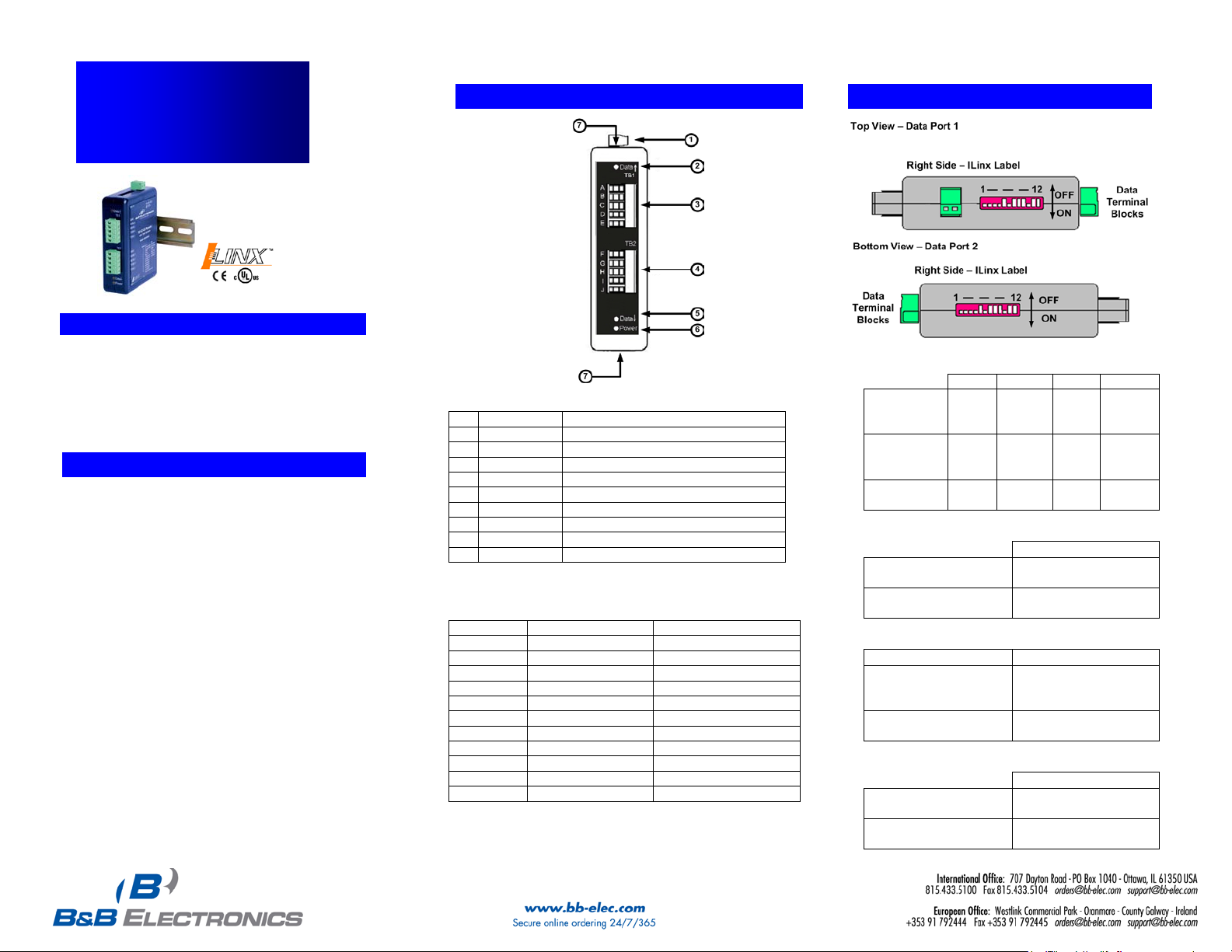
1
Power TB
2 Position, Removable
2
Data Received on TB1
3
TB 1
5 Position, Removable
4
5
DATA LED
Red Flashes when RS-422/485
Data Transmitted on TB2
6
Power LED
Red, ON When Power Applied
7
Dip Switch
12 Position, One on the top of the
Unit, on the bottom of the unit
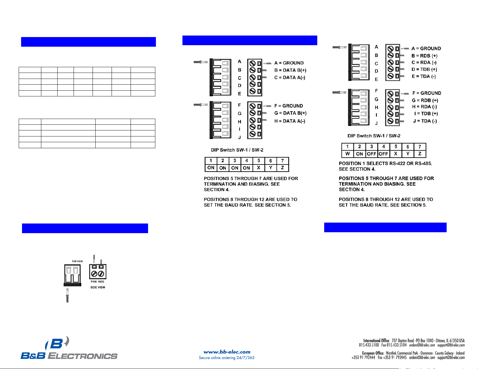
TB1
RS-485 2-Wire
RS-422/485 4-Wire
A
GND
GND
B
Data B(+)
RDB(+)
C
D
---
TDB(+)
E
---
TDA(-)
TB2
RS-485 2-Wire
RS-422/485 4-Wire
F
GND
GND G Data B(+)
RDB(+)
H
Data A(-)
RDA(-)
I
---
TDB(+)
J
---
TDA(-)
RS-485
2-Wire
Half Duplex
RS-485
4-Wire
Full Duplex
Full Duplex
5
Use the 120Ω
Built in Termination
Use External
or no termination
Bias Resistor
Use External or no
Transmit Bias Resistor
Use the 1.2KΩ Receive
Bias Resistor
Transmit Bias Resistor
ILinx 485OPDRI
Triple Isolated RS-422/485
Repeater
11.. CChheecckk ffoorr RReeqquuiirreedd HHaarrddwwaarree
ILinx 485OPDRI Isolated Repeater
This Quick Start Guide
Additional Items Required but not included
o A 10 to 48 VDC Power Supply.
o RS-422/485 Cables.
IInnffoorrmmaattiioonn –– UULL CCllaassss 11 DDiivv 22
22..
1. Power, input /output (I/O) wiring must be in
accordance with Class 1 Division 2 wiring methods
[Article 501.10(B) of the National Electric code,
NFPA70] and in accordance with the local authority
having jurisdiction.
2. Maximum ambient air temperature 80°C
3. WARNING – EXPLOSION HAZARD:
SUBSTITUTION OF ANY COMPONENTS MAY
IMPAIR SUITABLITY FOR CLASS 1, DIVISION 2.
4. WARNING – EXPLOSION HAZARD: WHEN IN
HAZARDOUS LOCATIONS, TURNING OFF
POWER BEFORE REPLACING OR WIRING
MODULES
5. WARNING – EXPLOSION HAZARD: DO NOT
DISCONNECT EQUIPMENT UNLESS POWER HAS
BEEN SWITCHED OFF OR THE AREA IS KNOWN
TO BE NON-HAZARDOUS.
6. WARNING – THIS APPARATUS IS SUITABLE FOR
USE IN CLASS 1 DIVISION 2, GROUPS A, B, C,
AND D, OR UNCLASSIFIED AREAS
.
IInnffoorrmmaattiioonn –– FFrroonntt PPaanneell
33..
Front Panel
DATA LED Red, Flashes when RS-422/485
TB 2 5 Position, Removable
RS-422/485 Terminal Blocks
Data A(-) RDA(-)
Documentation Number – p/n 8455r002 485OPDRI-2212qsg
©2010 B&B Electronics Manufacturing Company
IInnffoorrmmaattiioonn -- DDIIPP SSwwiittcchh
44..
Communications Mode
1 2 3 4
ON ON ON ON
RS-422
Termination Resistor
ON OFF OFF OFF
OFF OFF OFF OFF
ON
Transmit Bias
Use the 1.2KΩ
Transmit
Receive Bias
Use External or no
OFF
6
OFF
ON
7
OFF
ON
Page 2
RS-422 / Four Wire RS-485
Switch Selectable
Baud Timeout
2.4
ON
OFF
OFF
OFF
OFF
4.37
4.8
OFF
ON
OFF
OFF
OFF
2.03
19.2
OFF
OFF
OFF
ON
OFF
0.57
38.4
OFF
OFF
OFF
OFF
ON
0.27
Resistor Selectable
Baud
Timeout
(Kbps)
8 through 12
R-7 / 28 Value
(ms)
1.2
OFF
820 KΩ
8.32
57.6
OFF
16 KΩ
0.16
115.2
OFF
8.2 KΩ
0.08
230.4
OFF
4.3 KΩ
0.04
460.8
OFF
2.2 KΩ
0.02
RRSS--442222//448855 TTiimmee OOuutt
55..
(Kbps) 8 9 10 11 12 (ms)
9.6 OFF OFF ON OFF OFF 1.02
Pre-defined timeouts are set using switches 8 through 12.
Resistor selectable baud rates are set by inserting a through
hole resistors (R-7 and R-28) on the circuit board.
Timeout selections are equal to one character time at the
indicated baud rate. Setting the converter to 9600 will
generally work at 9600 and higher baud rates. In RS-422
mode, timeouts are not required.
WWiirriinngg EExxaammpplleess
88..
Two Wire RS-485
Documentation Number – p/n 8455r002 485OPDRI-2212qsg
©2010 B&B Electronics Manufacturing Company
PPoowweerr CCoonnnneeccttiioonn
66..
Power Requirements:
10 – 48 VDC @ 0.2A
n
99.. OOppeerraattiioon
1. During normal operation, the Power LED
should be illuminated.
2. When data is sent or received on either port,
the corresponding Data LED should flash.
 Loading...