

Page 1
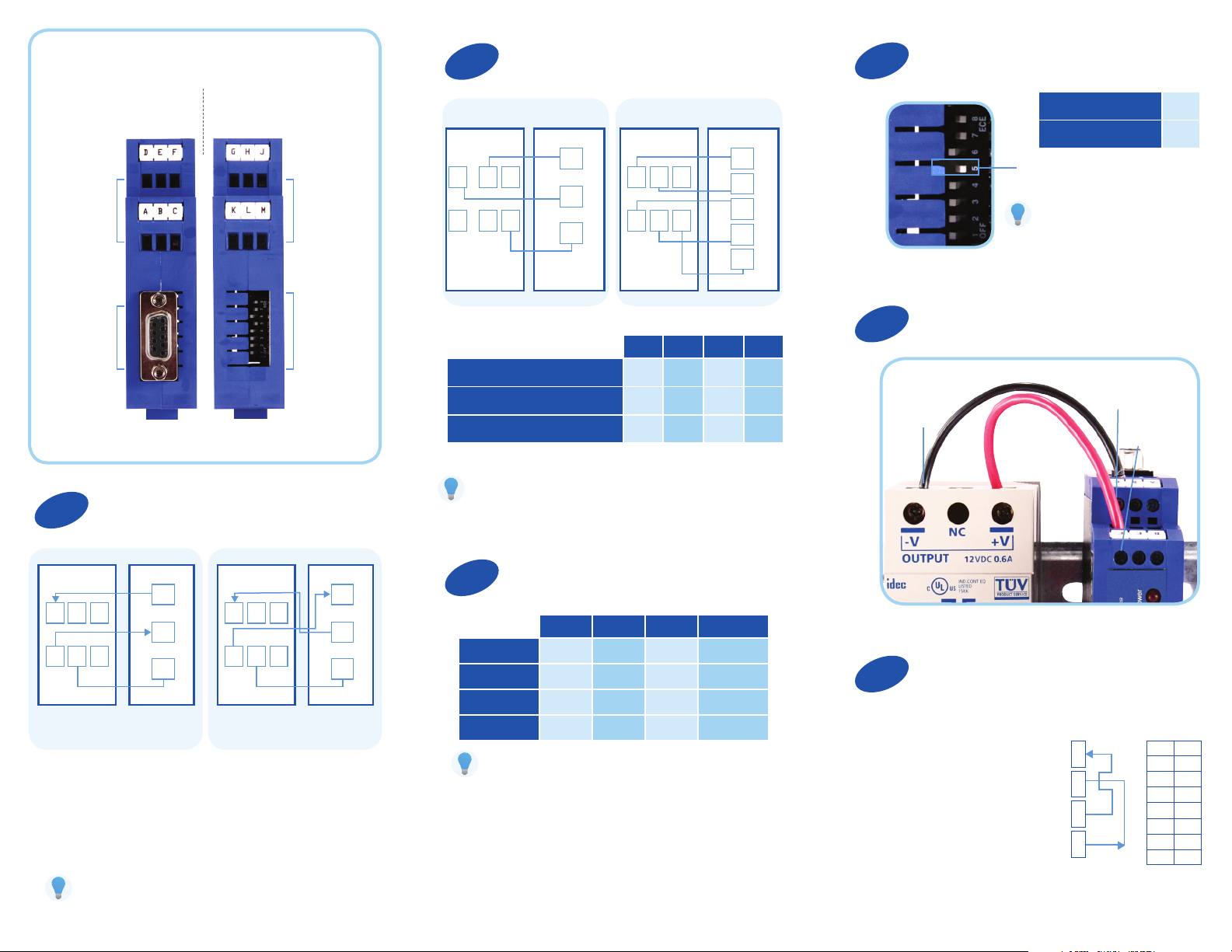
Product Overview
Set The 422/485 Side of Converter
2
Termination Switch: Set to OFF (Recommended)
4
Top View
(232 and Power Side)
Bottom View
(422/485 Side)
Terminal Block
Connectors
A – F
DB9 F PINS
Please Note:
Terminal block and DIP switch settings located on product.
1
Connect Your RS232 Device
(Terminal Block OR DB9 Port)
Terminal Block
Connectors
G – M
DIP Switches
1 – 8
2 Wire 485 4 Wire 485/422
Your Device Your Device485LDRC9 485LDRC9
DATA
B (+)
G
HLJ
K
RS-485 2-Wire Half Duplex
RS-485 4-Wire Full Duplex
RS-422 Full Duplex
M
Additional tech notes on 422/485 are located at:
http://www.bb-elec.com/485LDRC9
DATA
A (-)
GND
G
KHLJM
SW-1 SW-2 SW-3 SW-4
ON ON ON ON
ON OFF OFF OFF
OFF OFF OFF OFF
RDA (-)
RDB (+)
TDA (-)
TDB (+)
GND
Connect Your Power Supply
5
External Power
Supply
Use the 120Ω
Built-in Termination
Use External or
No Termination
Switch 5
If you want to enable termination,
refer to: ht tp://www.bb -elec.com/
485LDRC9
Terminal C:
(Ground/V (–)
Terminal F:
V (+)
ON
OFF
D
AEBFC
Computer
Your Device485LDRC9
TD
D
RD
AEBFC
GND
DTE DCE
Field Device
Your Device485LDRC9
TD
RD
GND
• Use a straight through DB9 to DB9 if you are
connecting to a computer (DTE).
• Use a cross over (null modem) DB9 to DB9
if you are not connecting to a computer. (DCE)
Additional tech notes on RS232 DTE DCE connections
are located at: ht tp://ww w.bb - el ec.com/tech/DTE- DCE
Set the Dipswitch Settings for Baud Rate
3
SW-6 SW-7 SW-8 Timeout (MS)
2400
4800
9600
19.2K
For baud rates not listed above refer to:
http://www.bb-elec.com/485LDRC9
OFF OFF ON 4.16
OFF ON OFF 2.08
ON OFF OFF 1.04
ON ON ON 0.580
Converter uses 0.5 W
Loopback Test (Optional)
6
To verify serial port and 485LDRC9 functionality
• Congure for RS- 485 four wire,
9600 baud.
• Jumper terminals H to L and G to K.
• Connect a PC to the RS-232 port
(see Step 1).
• Using HyperTerminal or similar program,
connect to the appropriate COM port
(remember to set the baud rate at 9600).
Turn off HyperTerminal local echo.
• Start typing. If you can see the data
you are typing, you have a good loop-
back. If you cannot, contact tech support.
• LED Indicators: Power is ON when power
is applied. TD flashes when RS-422/485
data is sent. RD flashes when RS-422/485
data is received.
Set DIP
Switches to:
ON
L
K
H
G
1
OFF
2
OFF
3
OFF
4
5
OFF
6
OFF
7
OFF
8
RS-485 4-Wire
ON
Page 2
Troubleshooting
Timing Issues?
(Usually applies when using 2-wire 485)
The 485LDRC9 uses RC time constant. This means that when you
are setting the DIP switches for the “baud rate” you are setting a
turnaround time, not a “baud rate”.
Sometimes the turnaround time on a RS-485 2-wire device does not
match the turnaround time that is set on the 485LDRC9, even though
they are both set for the same baud rate. Refer to the chart in
Step 3 to match the turnaround time of your RS-485 2-wire device.
If you do not know the turnaround time of your device you can do the
following:
• Keep your device at its current baud rate, but change
the “baud rate” on the 485LDRC9. Set it for one
or two steps above or below the baud rate of your
device until you get communication.
• Alternatively, you can use the 485DRCi-PH instead of
the 485LDRC9. The 485DRCi-PH uses bitwise control
so you do not have to worry about matching the
timing of your device.
Check Type of Cable Used
A 24 gauge twisted pair, shielded cable is preferred. Category
5 cable is available as shielded twisted pair (STP), as well
as unshielded twisted pair (UTP) and generally exceeds the
recommendations for RS-422, making it an excellent choice
for RS- 422 and RS-485 systems.
Are You Hooking a Signal Ground
(common, reference) on the RS-422/485 side?
The specications for most RS-422 and RS-485 devices indicate that
the device can withstand a maximum VCM of -7 volts to +12 volts.
The function of the GND connection is to tie the signal grounds of all
nodes on a network to one common ground potential. This ensures
that the common mode voltage cannot exceed the specied value.
A signal ground is required on the 485LDRC9 because it is an
optically isolated device. If you do not have a signal ground
(common, reference) on your RS422/485 device, you can hook to the
DC power ground of your RS422/485 device.
Caution: Make sure that this is connected correctly.
Note: Do not use the shield drain wire as the signal ground between RS-422/485 devices.
RS-422/485 systems may communicate successfully without the signa l ground when nodes
are located close togethe r and circuit grounds for all nodes are at the same potential--e.g., a
controlled lab environment. However, this practice is not recommended. If a signal ground is
not used when nodes are separated by distance, and there is the possibility of lightning and/
or other electrical noise, the common mode voltage can rise to levels that could compromise
communications, or even damage the transceivers in the system nodes.
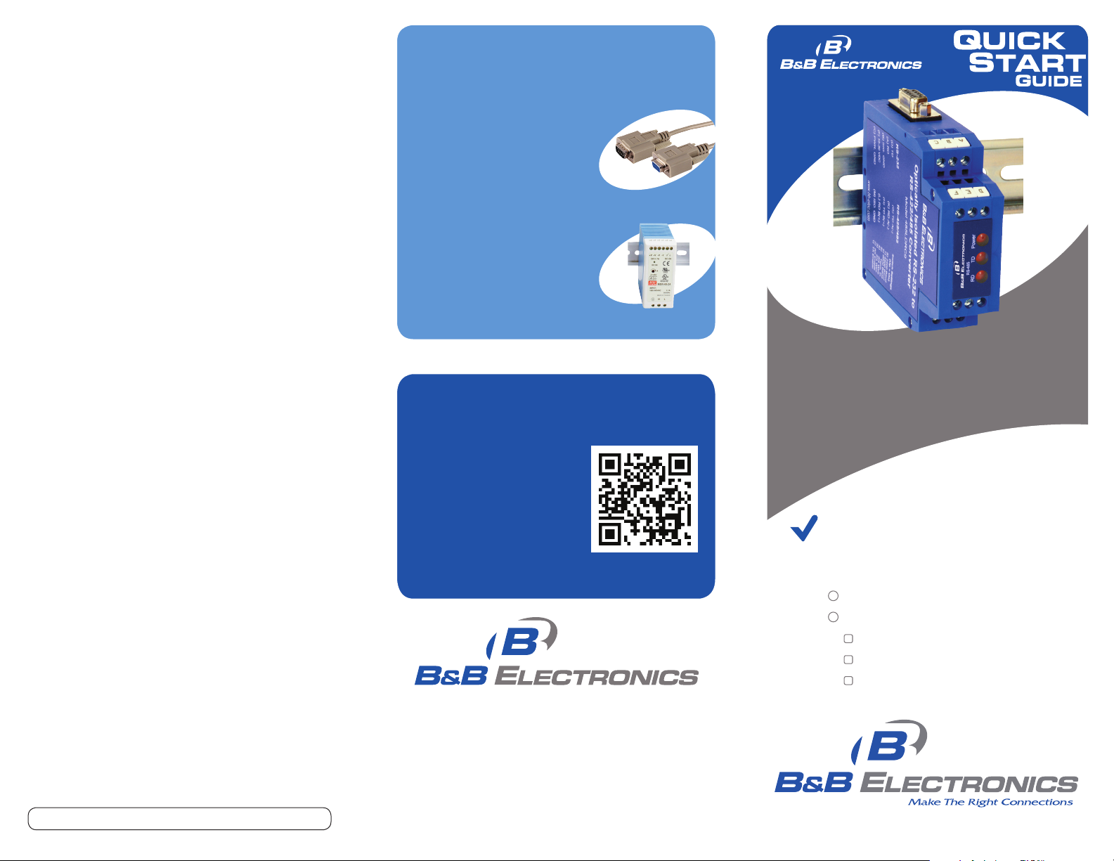
Recommended Accessories
and Power Supplies
Ready To Use Cables For
Serial And USB
http://www.bb-elec.com/485LDRC9/
ACC
9PA M F6
Industrial Power Supplies
http://www.bb-elec.com/485LDRC9/
ACC
MDR- 40 -24
Fast, Easy Answers
• First, check step 6.
• Then use your smart
phone to access complete
documentation on our
web site. Simply scan
the code to the right.
http://www.bb-elec.com/485LDRC9
1-888-948-2248 | Europe: +353 91 792444
www.bb-elec.com
485LDRC9
Optically Isolated
RS-232 to RS-422/485 Converter
First Things First...
Before you begin, be sure you have
the following:
485LDRC9 Serial Converter
Additional items required but not included:
Power Supply
RS-232 Cable
RS-422/485 Cable
Document number – p/n 8413 r003 485LDRC9 - 1112
707 Dayton Road | PO Box 1040 | Ottawa, IL 61350
Phone: 815-433-5100 | Fax: 815-433-5109
www.bb-elec.com | E-mail: info@bb-elec.com
© 2012 B&B Elect ronics Manu facturing Company
Fast and easy on the web:
www.bb-elec.com
Page 3

485LDRC9
Optically Isolated
RS-232 to RS-422/485 Converter
UL Installation Information
Underwriters Laboratories Conditions of Acceptability –
When installed in the end-use equipment, consideration
should be given to the following:
1. The wiring terminals are suitable for factory wiring only.
2. This device is to be mounted in a suitable enclosure
in the end-product.
3. This device is suitable for operation at a maximum surrounding
air temperature as described in the documentation.
4. These devices are intended for use in a pollution
degree 2 environment.
• Input Voltage: 10 – 30 VDC
• Input Power: 0.5 Watts
• Wire Range: 12 – 24 AWG
• Tightening Torque: 4 kgf-cm
• Temperature rating of eld installed conductors is 105° C
minimum, sized for 60° C ampacity
• Use copper wire only
• Maximum surrounding ambient air temperature 80° C
Document number – p/n 8413 r003 485LDRC9 - 1112
 Loading...