

Page 1
© 2003 by B&B Electronics. All rights reserved.
www.bb-elec.com orders@bb-elec.com support@bb-elec.com
International Office: 707 Dayton Road PO Box 1040 Ottawa, IL 61350 USA 815-433-5100 Fax 433-5104
European Office: Westlink Commercial Park Oranmore Co. Galway Ireland +353 91 792444 Fax +353 91 792445
PRODUCT INFORMATION B&B ELECTRONICS
Switch 1
TX Enable
Switch 2
RX Enable
Switch 3
2/4 Wire
Switch 4
2/4 Wire
RS-485 2-Wire Mode
(half-duplex)
ON
ON
ON
ON
RS-485 4-Wire Mode
(full-duplex)
ON
OFF
OFF
OFF
RS-422 Mode
(full-duplex)
OFF
OFF
OFF
OFF
Switch
6
Switch
7
Switch 8 R11
Time (ms)
1200
OFF
OFF
OFF
820k
8.33
2400
OFF
OFF
ON
Not Used
4.16
4800
OFF
ON
OFF
Not Used
2.08
9600
ON
OFF
OFF
Not Used
1.04
19200
ON
ON
ON
Not Used
.580
38400
OFF
OFF
OFF
27k
.260
57600
OFF
OFF
OFF
16k
.176
115200
OFF
OFF
OFF
8.2k
.0868
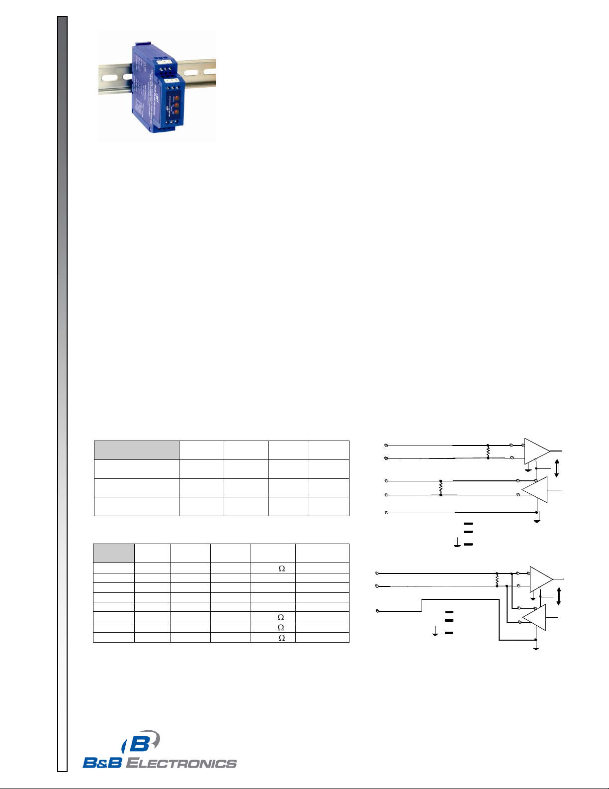
TYPICAL TWO-WIRE RS-485 SETUP
Generator
Receiver
Circuit ground
DATA +
(TERMINAL BLOCK H)
GND
(TERMINAL BLOCK M)
DATA -
(TERMINAL BLOCK G)
G
RRtBGARB
A
RX
TX
485DRC/485LDRC
TYPICAL RS-422/485 4 WIRE
GND
(TERMINAL BLOCK M)
TD A -
(TERMINAL BLOCK G)
TD B +
(TERMINAL BLOCK H)
RD A -
(TERMINAL BLOCK K)
RD B +
(TERMINAL BLOCK L)
Receiver
Circuit ground
Generator
R
G
R
Rt
Rt
B
AAB
ENABLE
G
RX
TX
485DRC/485LDRC
485LDRC-0812-1/3
Models 485DRC and 485LDRC
Industrial DIN Rail Mounted
Optically Isolated RS-232 to
RS-422/485 Converters
With Surge Suppression
Introduction
The DIN Rail mountable Models 485DRC and 485LDRC optically isolate and convert unbalanced, full or half-duplex
RS-232 signals to optically isolated, balanced, full or half-duplex RS-422 or RS-485 signals at baud rates up to 115.2
kbps. These units also surge suppress the RS-422/485 lines. They feature Send Data Control circuitry so no software
control of handshake lines is required in RS-485 mode.
LEDs
The 485LDRC includes all the above features plus 3 LED’s: one indicating RS-485 Transmit Data, one for RS-485
Receive Data, and one for power.
Description
The 485DRC/485LDRC has screw down terminal blocks on the RS-232 side and the RS-422/RS-485 side. Transmit
(TD), Receive (RD) and Ground are supported on the RS-232 side. The unit is powered by a supply voltage of 10 to
30VDC on the RS-232 side, useful where 24VDC is commonly found. Transmit Data A (-), Transmit Data B (+), Receive
Data A (-), Receive Data B (+), and Ground are supported on the RS-422/RS-485 side. Communication features on the
485DRC/485LDRC are dipswitch selectable on the unit.
RS-485 Mode with Send Data Control
Send Data Control recognizes the first bit of data from the RS-232 side, enables the transmitter and disables the
receiver. After the last bit of data is sent from the RS-232 side, the timeout waits one character length, then disables the
transmitter and enables the receiver. The timeout can be selected with dipswitches or by changing the value of R11 (see
Table 2). If the system requires the line to be “turned around” faster, i.e. the slave device starts responding before the
transmitter of the 485DRC/485LDRC is disabled, R11 can be changed to meet the specific baud rate. Termination
resistance can be selected with Switch 5 for high baud rates and long cable distances. See B&B Electronics’ RS-422/485
Application Note available on the website or by mail. Factory setting: 9600 baud.
Table 1. Typical Communication Setups
Table 2. Baud Rate Selection
In a two-wire setup, switches 3 & 4 should be “ON”, making terminal block (G)
the Data (–) line and terminal block (H) the Data (+) line.
Page 2
© 2003 by B&B Electronics. All rights reserved.
www.bb-elec.com orders@bb-elec.com support@bb-elec.com
International Office: 707 Dayton Road PO Box 1040 Ottawa, IL 61350 USA 815-433-5100 Fax 433-5104
European Office: Westlink Commercial Park Oranmore Co. Galway Ireland +353 91 792444 Fax +353 91 792445
PRODUCT INFORMATION B&B ELECTRONICS
485LDRC-0812-2/3
Terminal Block Configuration
RS-232
(D) TD (input)
(A) RD (output)
(B) SIG. GND
(F) +10 to 30VDC
(C) PWR. GND
RS-422/485
TDA (G) Tx inverted or (-) (output)
RDA (K) Rx inverted or (-) (input)
TDB (H) Tx non-inverted or (+) (output)
RDB (L) Rx non-inverted or (+) (input)
ISO. GND (M) Isolated RS-422/485 Signal Ground/Common
Switch Settings (UP = ON)
1 - Tx Enable (On for 485 mode. Off for 422 mode.)
2 - Rx Enable (On for 2-wire 485 mode. Off for 4-wire 485 and 422 mode.)
3 - 2/4 Wire (On for 2-wire/half duplex. Off for 4-wire full duplex.)
4 - 2/4 Wire (On for 2-wire. Off for 4-wire.)
5 - Termination Resistors (On for termination. Off for no termination.)
6 - 9600 Baud (On for 9600, Off for others. See Table 2 for additional baud rates.)
7 - 4800 Baud (On for 4800, Off for others. See Table 2 for additional baud rates.)
8 - 2400 Baud (On for 2400, Off for others. See Table 2 for additional baud rates.)
Page 3

© 2003 by B&B Electronics. All rights reserved.
www.bb-elec.com orders@bb-elec.com support@bb-elec.com
International Office: 707 Dayton Road PO Box 1040 Ottawa, IL 61350 USA 815-433-5100 Fax 433-5104
European Office: Westlink Commercial Park Oranmore Co. Galway Ireland +353 91 792444 Fax +353 91 792445
PRODUCT INFORMATION B&B ELECTRONICS
DECLARATION OF CONFORMITY
Manufacturer’s Name: B&B Electronics Manufacturing Company
Manufacturer’s Address: P.O. Box 1040
707 Dayton Road
Ottawa, IL 61350 USA
Model Number: 485DRC and 485LDRC
Description: RS-485 Converter Optical Isolated DIN Converters
Type: Light industrial ITE equipment
Application of Council Directive: 89/336/EEC
Standards: EN 55022
EN 61000-6-1
EN 61000 (-4-2, -4-3, -4-4, -4-5, -4-6, -4-8, -4-11)
Robert M. Paratore, Director of Engineering
485LDRC-0812-3/3
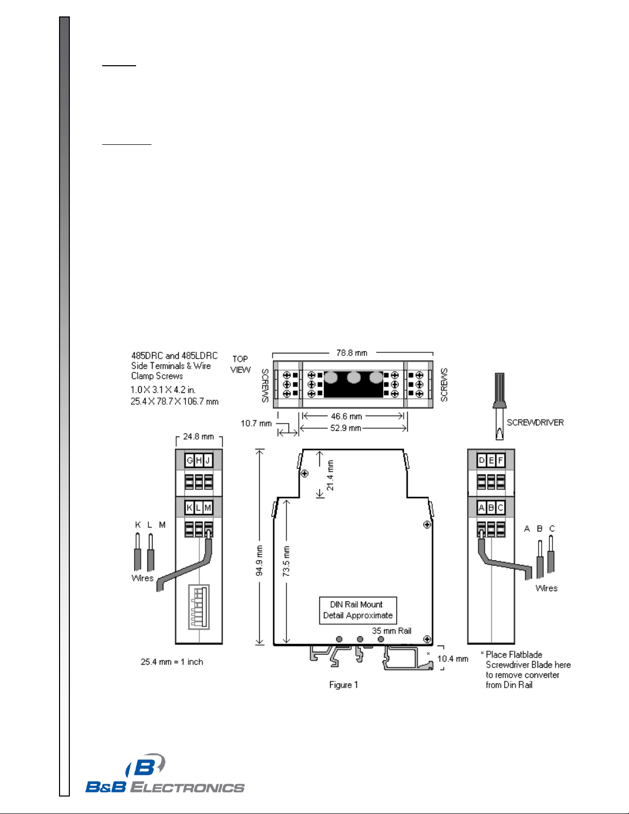
Removing Converter from DIN Rail
A flat blade screwdriver will be needed when removing the 485DRC / 485LDRC from a 35mm DIN rail.
1. Place a flat blade screwdriver blade in disengage clip on the converter enclosure (See Figure 1).
2. Gently pry on screwdriver handle.
3. Rock enclosure toward you to release it from the DIN rail.
Specifications
Dimensions: 4.2 x 3.1 x 1.0 in (106.7 x 78.7 x 25.4mm)
Temperature Range: -40 to +80°C (-40 to +176°F)
Humidity Range: 0 to 95% non-condensing
Supply Voltage: +10 to 30VDC @ 100mA
+9 to 30 VAC @ 100 mA
Data Rates: 1200 to 115.2 kbps
2400 to 19200 kbps switch selectable
Connectors: Screw down terminal blocks for RS-232 and RS-422/485 sides
LED’s: (485LDRC only) – Transmit Data, Receive Data and Power
Isolation: 2000VAC Optical Isolation of Data Signals and Ground
Surge Suppression: 7.5V, bi-directional avalanche breakdown device
500W peak power dissipation
Clamping time < 1 picosecond (theoretical)
 Loading...