

Page 1
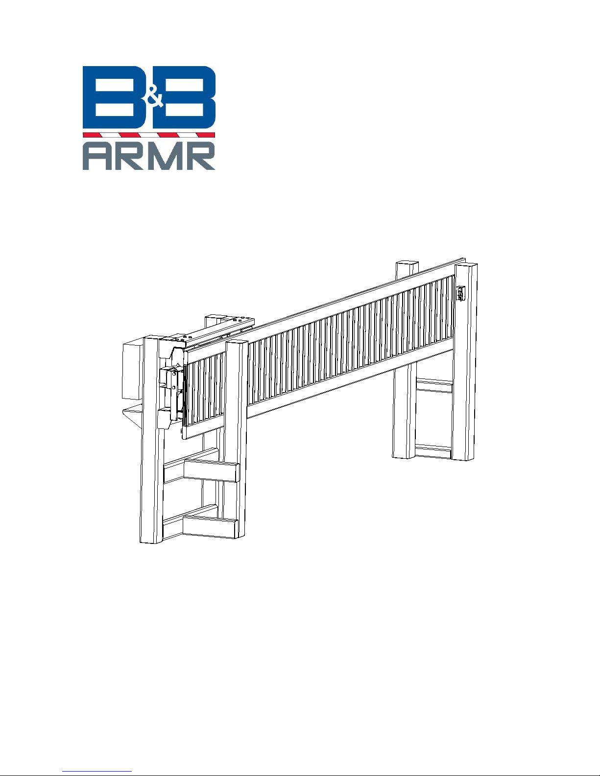
MODEL 480 SERIES
SLIDING GATE
OPERATIONS & MAINTENANCE
MANUAL
B&B ARMR CORPORATION
CORPORATE AND TECHNICAL SUPPORT:
2009 CHENAULT DRIVE 1934 OLD GALLOWS ROAD
CARROLLTON, TX 75006
SUITE 114
PHONE: (800) 367-0387
FAX: (972) 385-9887
© 2006 B&B ARMR Corporation 0480-9001 Revision A3
FIELD SERVICE:
VIENNA, VA 22182
PHONE: (703) 752-6108
FAX: (703)752-6288
MADE IN THE USA
Page 2
Installation and Operations Manual — Model 480 Series INTRODUCTION ii
Your safety is extremely important to us. If you have any
questions or are in doubt about any aspect of the equipment,
please contact us.
INTRODUCTION
Welcome!
Congratulations on your purchase of a B&B ARMR vehicle barrier. In addition to
providing detailed operating instructions, this manual describes how to install, maintain,
and troubleshoot your vehicle barrier. If you require additional assistance with any
aspect of your vehicle barrier's installation or operation, please contact us.
We have years of experience in all aspects of perimeter security and related disciplines,
and our products are used throughout the world to control access and to protect people,
equipment, and facilities. We offer a broad range of vehicle barrier and related security
services:
Turnkey installations
Routine barrier preventative maintenance or emergency repairs (including
work on non-B&B ARMR products)
Spare or replacement parts
Custom designs or special installations
Equipment upgrades (modernize your old equipment with state-of-the-art
hydraulics and control systems)
Ancillary security equipment such as security guard enclosures, card readers,
security lighting, and many other security related products.
Safety
© 2006 B&B ARMR Corporation WWW.BB-ARMR.COM (800)-367-0387
Page 3
Installation and Operations Manual — Model 480 Series INTRODUCTION iii
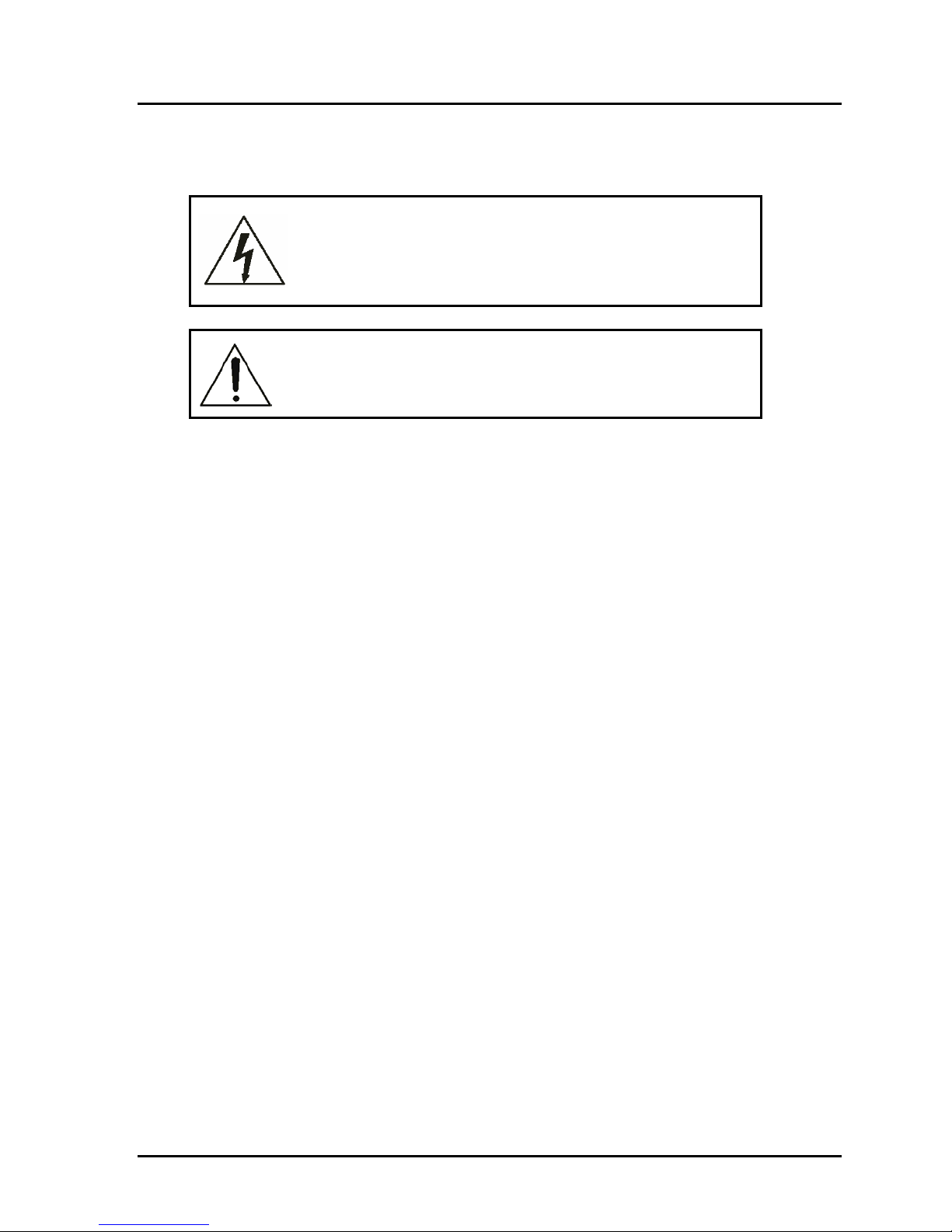
SYMBOL MEANING:
The lightning flash with arrowhead symbol, within an
equilateral triangle, is intended to alert the user to the
presence of uninsulated "dangerous voltage" within the
product's enclosure that may be of sufficient magnitude to
constitute a risk of electric shock to persons.
The exclamation point within an equilateral triangle is
intended to alert the user to the presence of important
operating and maintenance (servicing) instruction in the
literature accompanying the product.
B&B ARMR does not assume responsibility for injury to persons or property during
installation, operation, or maintenance. As the user, you are responsible for correct and
safe installation, operation, and maintenance of this equipment. Users must follow the
specific instructions and safety precautions located in this manual. In addition they must:
Follow the safety standards of the Occupational Safety and Health Administration
(OSHA), as well as other applicable federal, state, and local safety regulations and
industry standards and procedures. For installation outside the United States, users must
also follow applicable international, regional, and local safety standards.
Engage only trained and experienced staff to install, operate, and maintain the equipment.
Ensure that all repairs are performed correctly, using properly trained technicians and the
correct tools and equipment.
Additional safety devices may be included with this barrier system:
o Vehicle loop detector(s) – Safety loop
o Traffic arms
o Traffic lights
How to Contact Us
If you have any questions or experience any problems with your vehicle barrier—or if we
can help you with any other facility security issues—please contact us directly at:
Corporate And Technical Support: Field Service:
2009 Chenault Drive 1934 Old Gallows Road
Carrollton, TX 75006
Suite 114
Phone: (800) 367-0387
Fax: (972) 385-9887
© 2006 B&B ARMR Corporation WWW.BB-ARMR.COM (800)-367-0387
Vienna, VA 22182
Phone: (703) 752-6108
Fax: (703)752-6288
Page 4

Installation and Operations Manual — Model 480 Series TABLE OF CONTENTS 5
Table of Contents
INTRODUCTION........................................................................................................ii
Safety..............................................................................................................................ii
How to Contact Us ...................................................................................................... iii
1 ORIENTATION ...................................................................................................5
1.1 Overview...................................................................................................................................... 5
1.1.1 Drive Stanchion ...................................................................................................................... 6
1.1.2 Receiving Stanchion ............................................................................................................... 6
1.1.3 Gate Section............................................................................................................................ 6
1.1.4 Operator.................................................................................................................................. 6
1.1.5 Battery Compartment .............................................................................................................7
1.1.6 Battery Control Box................................................................................................................ 7
1.1.7 Support Wheels....................................................................................................................... 7
1.1.8 Drive Wheels/Pinion............................................................................................................... 7
1.1.9 Options ................................................................................................................................... 7
1.2 Final Pre-operation Checklist..................................................................................................... 7
2 OPERATION ........................................................................................................8
2.1 Introduction................................................................................................................................. 8
2.2 Control ........................................................................................................................................ 8
2.3 Operating Time............................................................................................................................ 9
3 MAINTENANCE .................................................................................................9
3.1 Introduction................................................................................................................................. 9
3.2 Spare Parts.................................................................................................................................. 9
3.3 Monthly Inspections .................................................................................................................. 10
3.4 Six-Month Inspections ............................................................................................................... 11
3.5 Annual Maintenance Inspections............................................................................................... 11
4 TROUBLESHOOTING ......................................................................................11
4.1 Model 480 Troubleshooting Guide............................................................................................ 12
5 WARRANTY........................................................................................................ 14
6 APPENDIX.......................................................................................................... 14
Equipment Maintenance Log Form ......................................................................................................... 15
© 2006 B&B ARMR Corporation WWW.BB-ARMR.COM (800)-367-0387
Page 5
Installation and Operations Manual — Model 480 Series ORIENTATION 5
1 ORIENTATION
1.1 Overview
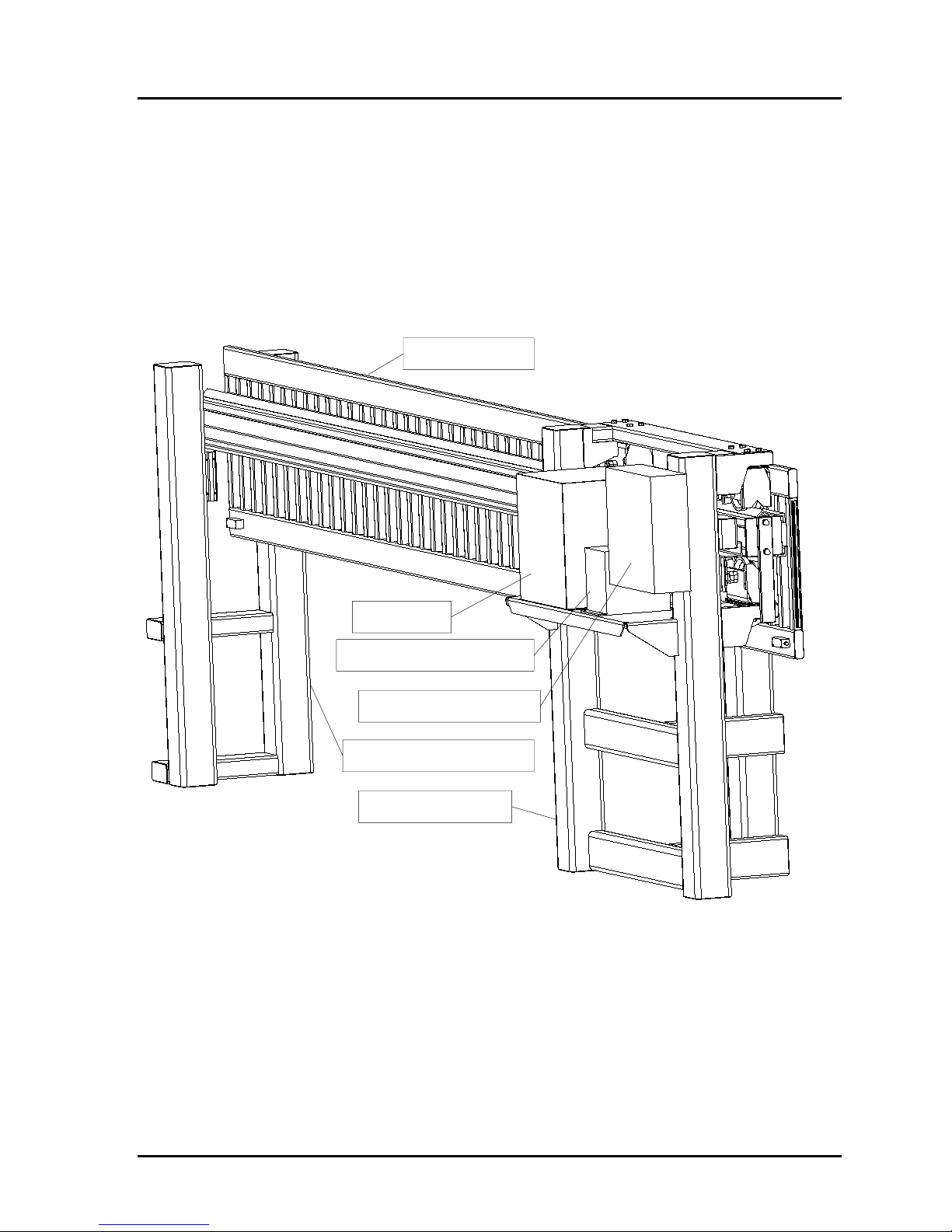
The model 480 vehicle barrier is designed to contain a vehicle impact and prevent that
vehicle from entering a restricted access control area. The barrier consists of two cast in
place foundation stanchions, the cantilever gate panel, and barrier drive operator.
3. Gate Section
4. Operator
5. Battery Compartment
6. Battery Control Box
2. Receiving Stanchion
1. Drive Stanchion
© 2006 B&B ARMR Corporation WWW.BB-ARMR.COM (800)-367-0387
Page 6
Installation and Operations Manual — Model 480 Series ORIENTATION 6
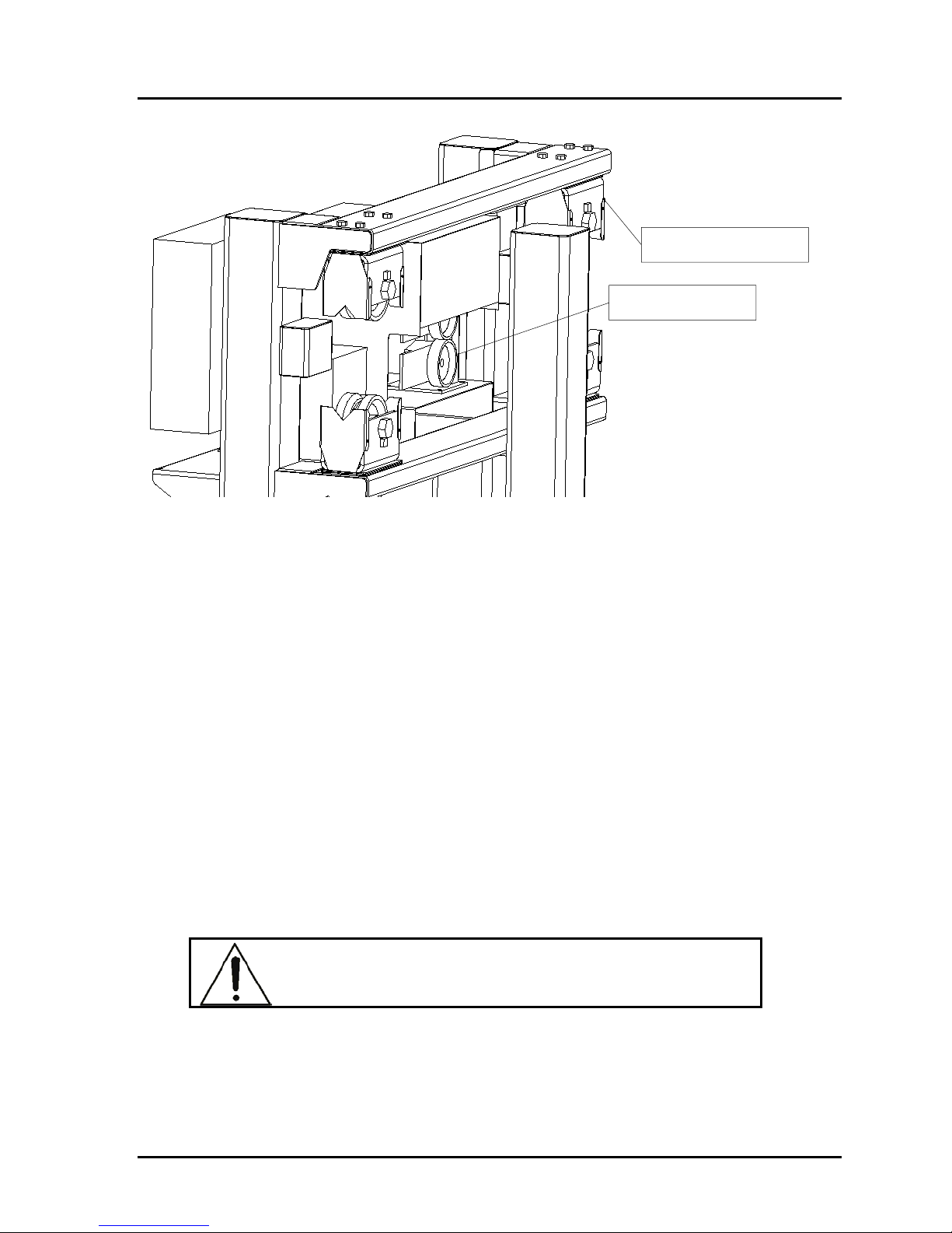
7. Support Wheels
8. Drive Wheels
Figure 1: Model 480 Cantilever Gate barrier
Figure 1 orients you to the basic components of the Model 480 vehicle barrier.
1.1.1 Drive Stanchion
The drive stanchion supports the main structure of the barrier as well as all the necessary
components to position the gate section closed and open. The “H” type design is
engineered to provide both operational structural integrity as well as crash impact
strength.
1.1.2 Receiving Stanchion
The receiving stanchion holds the gate section in place during crash impact. This
component also is engineered using the structural “H” section to allow for maximum
strength and rigidity.
1.1.3 Gate Section
The gate section provides the structure to move the impact force to the stanchions and
support the gate pickets. It is fabricated with a steel I-beam construction coupled with
vertical pickets.
CAUTION: This barrier is made of heavy steel components.
Ensure all personnel are cleared of area during operation.
1.1.4 Operator
The drive operator of the 480 barrier utilizes a LXLR production unit. Please refer to the
LXLR user and operations manual for further details.
© 2006 B&B ARMR Corporation WWW.BB-ARMR.COM (800)-367-0387
Page 7
Installation and Operations Manual — Model 480 Series ORIENTATION 7
CAUTION: Hydraulic hoses are under extreme pressure. Use
caution when working on barrier with access cover removed.
1.1.5 Battery Compartment
The battery compartment houses the back up battery system in the product. Please refer
to the LXLR user and operations manual for further information.
The batteries in this unit can produce high current. Extreme
care should be used during maintenance and service.
1.1.6 Battery Control Box
This box houses the control circuits used to monitor and charge the batteries.
1.1.7 Support Wheels
The V-grove support wheels guide the barrier and support the gate section. These steel
wheels are designed for long life and provide a cantilever solution which requires no
other guide support wheels.
1.1.8 Drive Wheels/Pinion
The standard LXLR operator used in this product includes a pair of pinch wheels to drive
the gate section during operation. Some products are equipped with a rack and pinion to
drive the gate. Operation is similar for either drive device. For further details on the
LXLR, please refer to the LXLR user and operations manual.
1.1.9 Options
The Model 480 vehicle barrier is available with a broad array of options and field
installed kits. Consult your ordering documentation to determine whether your system
has the optional equipment.
A traffic control gate arm to warn the vehicle operator. This gate arm is
positioned on the attack side of the barrier and does not open to allow traffic
until the barrier is fully open (stowed), and the gate lowers to block traffic
before the barrier starts to close (deploy).
Red/amber traffic lights. The light remains red if the gate is in any position
except fully open.
Infrared safety beams to detect pedestrian traffic or as an additional vehicle
sensing device.
1.2 Final Pre-operation Checklist
Before operating the Model 480 vehicle barrier, go through the checklist below and
verify that each of these steps has been completed.
© 2006 B&B ARMR Corporation WWW.BB-ARMR.COM (800)-367-0387
Page 8

Installation and Operations Manual — Model 480 Series INSTALLATION 8
CAUTION: For your safety, complete each of these steps
before operating the barrier!
Verify unit has hydraulic fluid to recommended level.
Verify control unit is plugged in and cable is routed clear of barrier operation.
Verify area is clear of personnel and other obstructions.
Ensure supplied power to drive unit matches product requirements.
Verify electrical hookups are completed per electrical wiring diagram
matching particular product.
It is recommended the unit be cycled 4 complete cycles prior to any vehicle or
pedestrian traffic.
2 OPERATION
2.1 Introduction
The barrier operates driving the pinch idler wheel into the pinion gear in the direction
commanded. The pinion is driven by a hydraulic motor and delivers the power to close
and open the gate.
2.2 Control
The 480 unit is controlled by an open/close/stop pushbutton station. The
station can be mounted on the 480 drive stanchion or at a remote guard station
or building. The push button station operates a PLC in the LXLR control
cabinet. Please reference LXLR manual for more details.
The gate will open, close and stop based on the input from the push button
station. The gate will not close if there is an object (vehicle, person, etc)
triggering the safety devices. If the gate has started to close and a safety is
triggered, the gate will reverse direction. The LXL operator is equipped with
an auto-close timer which is factory set at 10 seconds.
The gates are optionally connected with a key pad station on the safe side of
the barrier. The key pad is activated by a loop detector in the ground. If a
proper code is entered, the gate will open.
The gate can be manually operated by lifting the yellow release lever on the
operator. The lever has to be opened completely to prevent dragging on the
rack. It takes a minimum of 3 persons to manually push the sliding gate.
For emergency power off, the LXLR has a disconnect switch mounted below
the control cabinet. The battery back up system has two circuit breakers to
turn off.
The 480 gate should not be operated in heavy snow and ice unless the operator
and surrounding areas of the gate are cleared of the snow and ice.
© 2006 B&B ARMR Corporation WWW.BB-ARMR.COM (800)-367-0387
Page 9
Installation and Operations Manual — Model 480 Series MAINTENANCE 9
2.3 Operating Time
The operating time for the 480 gate is approximately 20-25 seconds to open and close.
The time is dependent on the gate length and the gate alignment. The pressure range is
300 psi to 800 psi depending on gate length and alignment.
3 MAINTENANCE
Do not attempt repairs unless you are trained and qualified.
This vehicle barrier can cause equipment damage and severe
injury if it is operated or maintained improperly.
3.1 Introduction
The Model 480 Series vehicle barriers are designed to be largely maintenance free. As
with any complex electromechanical device however, they must be regularly inspected to
ensure they are operating correctly. We recommend a simple monthly visual inspection
and a more thorough biannual inspection as described below. Please contact B&B ARMR
Technical Service Support for assistance with inspections, maintenance, or repairs if
needed.
Component damage is likely if a vehicle strikes the barrier. If this occurs, contact B&B
ARMR. We can help you assess the damage to make sure there is no hidden damage that
will compromise safety or effectiveness and help you determine which components
should be replaced.
3.2 Spare Parts
To ensure continuous gate performance, we recommend the following spare parts be kept
on hand per gate:
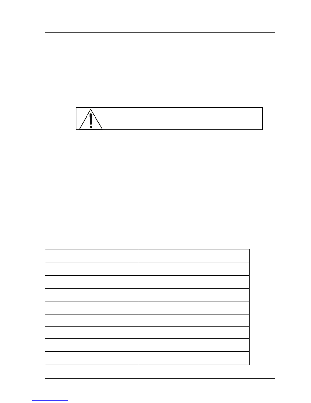
Part Number Description
XHYD-HOSE-LXL-1 HOSE ASSY, HYD. FEEDER
XHYD-HOSE-LXL-2 HOSE ASSY, HYD. JUMPER
XHYD-HOSE-LXL-3 HOSE ASSY, HYD. FEEDER
XHYD-VALVE-DC VALVE SOFT SHIFT, 24 VDC
XPCB-LXL-1-BB-A BOARD ASSY, LXL
XPLC-6ED1052 LOGO, 12/24 RC, 8I/40
XPLC-6ED1055 LOGO, EXPANSION MODULE
YR838-M50100SB RECTIFIER, 100 AMP, 480 VAC
XSEN-42GRL-9000 PHOTOELECTRIC SENSOR, TRANSMITTER
ALLEN BRADLEY
XSEN-42GRR-9002 PHOTOELECTRIC SENSOR,
RECEIVER,ALLEN BRADLEY
XDECT-LMA1200 LOOP DETECTOR
XCHGR-2903-1-24 BATTERY CHARGER
XSWI-P&FNBB15 SWITCH, PROX, P&F
XTRANS-MSP300 TRANSDUCER, PRESSURE
© 2006 B&B ARMR Corporation WWW.BB-ARMR.COM (800)-367-0387
Page 10

Installation and Operations Manual — Model 480 Series MAINTENANCE 10
XCONT-8900X24DC CONTACTOR, SINGLE POLE, 60 AMP, 24VDC
COIL
XRADIO-MWT02 DOOR EDGE TRANSMITTER, MILLER EDGE
XWHEEL-23345T15 V-GROOVE WHEEL, 8" X 4", MCMASTER
XLAMP-67W/120V LAMP, 67W, 120V
XRADIO-MWR03 RECEIVER, WIRELESS 3 CHANNEL
3.3 Monthly Inspections
We recommend you perform the following visual inspections monthly on the barrier
system. An equipment maintenance log is supplied in the appendix to assist in the
logging. Standard maintenance will require 1 man hours every 3 months and 8 man
hours every 6 months. The maintenance should be preformed by a mechanical person
and a certified electrician to certify the electrical systems is still performing correctly.
Tools required are screw drivers, phillips driver, and socket set.
Inspect the condition of the finish. If rust is present, wire brush and sand the
area then paint with a primer and a matching color.
Check oil for level, pressure, and condition in the HPU (Recommended oil:
Mobil EAL 224)
If oil is contaminated replace immediately (Recommended oil: Mobil EAL
224).
Check barrier for operation through normal cycles.
Adjust barrier speed to ensure proper operation. Check original submittal
documents for normal operating speed for close and open.
During the opening and closing cycles, verify the barrier operates smoothly
and does not bind. Also verify that the barrier does not hit with excessive
force when it is in the full-open or full-closed positions. If necessary, adjust
the barrier’s speed.
Check the hydraulic pumping unit for leaks at all points.
Visually inspect the operation and electrical contacts.
Tighten electrical contacts if required.
Check, adjust, and tighten all sensors (limit switches, proximity switches).
If applicable, check traffic lights and replace any burned bulbs or LEDs.
Check safety devices (loop, IR, etc.) for proper operation and report any
anomalies (if applicable).
Check the PLC for normal operation of all logic and functions.
Lubricate all pivot points.
Check hoses for wear and report any abnormalities.
Check the operation of the control panel(s).
Check the control panel’s buttons and lights for proper operation and replace
if necessary.
Follow LXLR maintenance procedures.
Inspect main 12V batteries and maintain every 3 months. Add fluid if
necessary or replace batteries if they will no hold a charge.
© 2006 B&B ARMR Corporation WWW.BB-ARMR.COM (800)-367-0387
Page 11

Installation and Operations Manual — Model 480 Series MAINTENANCE 11
Safety edge transmitters must have the 9V battery changed every 3 months to
prevent failure of the safety device
The 480 gate must be operated a minimum of 2-3 times per week. If the gate
has not been operated in a period of one month or more, the gate may need to
be pushed to get it to operator correctly.
Check the wear on the pinion, idler wheel, and V-groove wheels every 6
months. On the V-groove wheels the wear may cause the gate to become unlevel and the shimming may need to be adjusted or the wheels replaced.
Update the operation and maintenance log.
3.4 Six-Month Inspections
We recommend you perform the following inspections every six months.
Repeat the visual inspections in the monthly inspection list.
Turn the master power switch on the control circuit box to the OFF position.
Inspect the hydraulic system for signs of oil leaks.
The rack should be lubricated once every 6 months.
CAUTION: The hydraulic system when in operation is under
extreme pressure. Verify pressure on the barrier is completely
relieved prior to removal of any hydraulic fittings.
Check the hoses for wear or abrasion.
Check all fittings for tightness.
Inspect the oil level. Add oil as necessary. We recommend using
environmentally safe oil such as Mobil EAL 224.
Measure the resistance in any traffic loops and log the measurements and
report anomalies (if applicable).
When the inspection is complete, turn the power on and test cycle the barrier
to verify operation and control.
3.5 Annual Maintenance Inspections
We recommend you perform the following inspections annually.
Perform all quarterly maintenance steps.
Replace the hydraulic fluid.
4 TROUBLESHOOTING
The table below provides a general guidance on identifying and correcting any problems
with your Model 480 Series vehicle barrier. If you encounter problems that you cannot
fix, contact B&B ARMR and we will gladly work with you to correct them.
© 2006 B&B ARMR Corporation WWW.BB-ARMR.COM (800)-367-0387
Page 12

Installation and Operations Manual — Model 480 Series TROUBLESHOOTING 12
4.1 Model 480 Troubleshooting Guide
The table below provides guidance on identifying and correcting any problems with your
Model 480 Series vehicle barrier. Please refer to the LXLR O&M manual for more
detailed troubleshooting guides referring to the drive unit. If you encounter problems that
you cannot fix, contact B&B ARMR and we will gladly work with you to correct them.
Symptom Actions
1. Check power
2. Check overload protector
3. Check PLC output on pumping unit
4. Check that safeties are clear.
Barrier does not
close when
commanded on
control panel
Barrier does not
close when
commanded on
control panel
HPU pump will not
build up pressure but
is running
HPU pump will not
turn on
Barrier makes noise
during operation
5. Check push button operation
6. Check PLC input on pumping unit.
7. Check pressure gauge
8. Manually raise the barrier by depressing the directional control
valve to see if problem is mechanical or electrical.
9. Check for binding between moving plate and frame. Check
connection of linkage between frame and plate. Check for
foreign debris.
1. Check power
2. Check PLC output on pumping unit
3. Check that safeties are clear.
4. Check push button operation
5. Check PLC input on pumping unit.
6. Check for binding between moving plate and frame. Check
connection of linkage between frame and plate. Check for
foreign debris.
1. Check power
2. Close pressure relief valve
1. Check power
2. Check motor overload, press start.
3. Check motor starter.
4. Check low level switch.
5. Check pressure switch.
1. Check linkage between frame and plate. Be sure it is secure
and properly lubricated (dry graphite spray).
2. Check hinge area for debris and proper lubrication (dry
graphite spray).
3. Check hydraulic cylinder clevis pins for lubrication (multi-
grade grease).
© 2006 B&B ARMR Corporation WWW.BB-ARMR.COM (800)-367-0387
Page 13

Installation and Operations Manual — Model 480 Series TROUBLESHOOTING 13
Symptom Actions
1. Check that the pressure relief valve is closed (fully
Hydraulic unit
excessively hot
clockwise).
2. Check that the pressure switch is adjusted to shut the motor
off before 1900 PSI.
3. Check for correct voltages.
1. Check for mechanical binds.
Barrier moves too
slowly
2. Check flow control valve.
3. In extreme cold temperatures, a higher grade hydraulic fluid
may be required to keep viscosity constant.
Traffic indicator
light does not change
1. Check bulbs.
2. Check PLC outputs.
3. Check proper limit switch operation.
© 2006 B&B ARMR Corporation WWW.BB-ARMR.COM (800)-367-0387
Page 14

Installation and Operations Manual — Model 480 Series WARRENTY 14
5 WARRANTY
B&B-ARMR CORPORATION warranties for a period of one year, after delivery F.O.B.
plant, unless otherwise specified by Supplier, from failure of operation in ordinary use
and against defects due to faulty material or workmanship. Any defective equipment in
the Barrier shall be returned to the factory, at Supplier’s option, for repair or replacement,
and Supplier assumes no responsibility for service at any consumer site. Supplier is in no
event responsible for any labor costs under the warranty. Subject to the above limitation,
all service, parts, and replacements necessary to maintain the equipment as warranted
shall be furnished by the end user. Supplier shall not have any liability under these
specifications, other than for repair or replacement as described above for equipment
malfunction or equipment failure of any kind, caused for any reason, including, but not
limited to unauthorized repairs, improper installation, installation not performed by
Supplier personnel, nor by Supplier authorized personnel, failure to perform
manufacturer’s suggested routine maintenance, modifications, misuse, accident,
catastrophe, neglect, natural disaster, act of God or if at any time the power supplied to
any part of the Security Barrier falls short or exceeds the rate of tolerance for the
equipment.
The exclusive remedy for breach of any warranty by Supplier shall be the repair or
replacement at supplier’s option, of any defects in the equipment. IN NO EVENT
SHALL THE SUPPLIER OF SECURITY BARRIER BE LIABLE FOR
CONSEQUENTIAL OR SPECIAL DAMAGES OR ANY KIND OF DAMAGES TO
ANYONE. Except as provided herein, Supplier makes no warranties or representations
to consumer or to anyone else and consumer hereby waives all liability against Supplier
as well as any other person for the design, manufacture, sale, installation, and/or
servicing of the Security Barrier.
THE FOREGOING WARRANTIES ARE IN LIEU OF ALL OTHER WARRANTIES
EXPRESS OR IMPLIED, INCLUDING THE IMPLIED WARRANTY OF
MERCHANTABILITY AND FITNESS FOR A PARTICULAR PURPOSE. NO
OTHER WARRANTIES EXIST.
Any modification or alteration by anyone other than B&B-ARMR will render the
warranty herein as null and void.
6 APPENDIX
© 2006 B&B ARMR Corporation WWW.BB-ARMR.COM (800)-367-0387
Page 15
Installation and Operations Manual — Model 480 Series APPENDIX 15
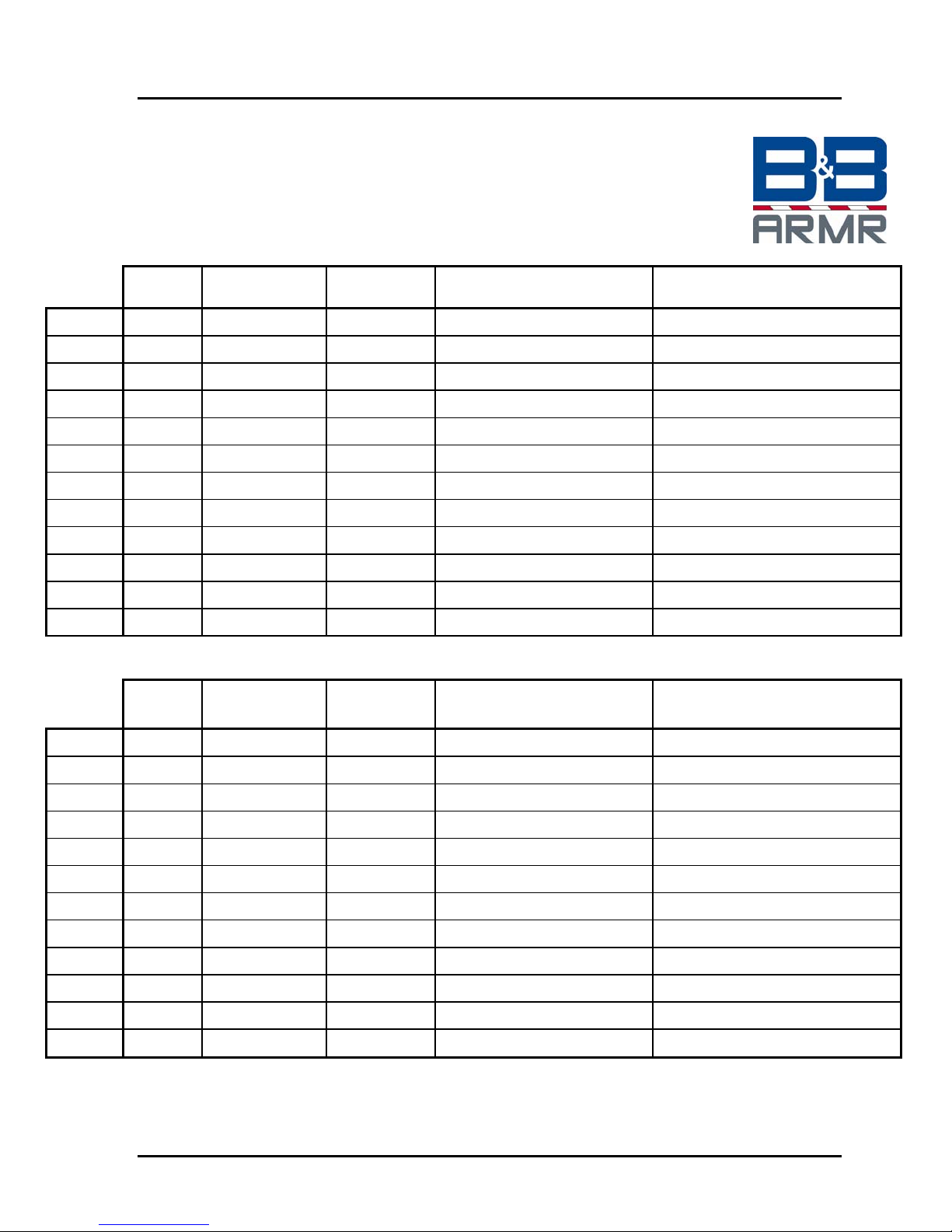
Equipment Maintenance Log Form
Product Type:________________________ B&B ARMR
800-367-0387
Location:____________________________ [email protected]
Date Performed By
Jan Yes No
Feb Yes No
Mar Yes No
Apr Yes No
May Yes No
Jun Yes No
Jul Yes No
Aug Yes No
Checklist
Complete
Anomalies Notes
Sep Yes No
Oct Yes No
Nov Yes No
Year Yes No
Date Performed By
Jan Yes No
Feb Yes No
Mar Yes No
Apr Yes No
May Yes No
Jun Yes No
Jul Yes No
Aug Yes No
Sep Yes No
Oct Yes No
Checklist
Complete
Anomalies Notes
Nov Yes No
Year Yes No
© 2006 B&B ARMR Corporation WWW.BB-ARMR.COM (800)-367-0387
 Loading...