

Page 1
e
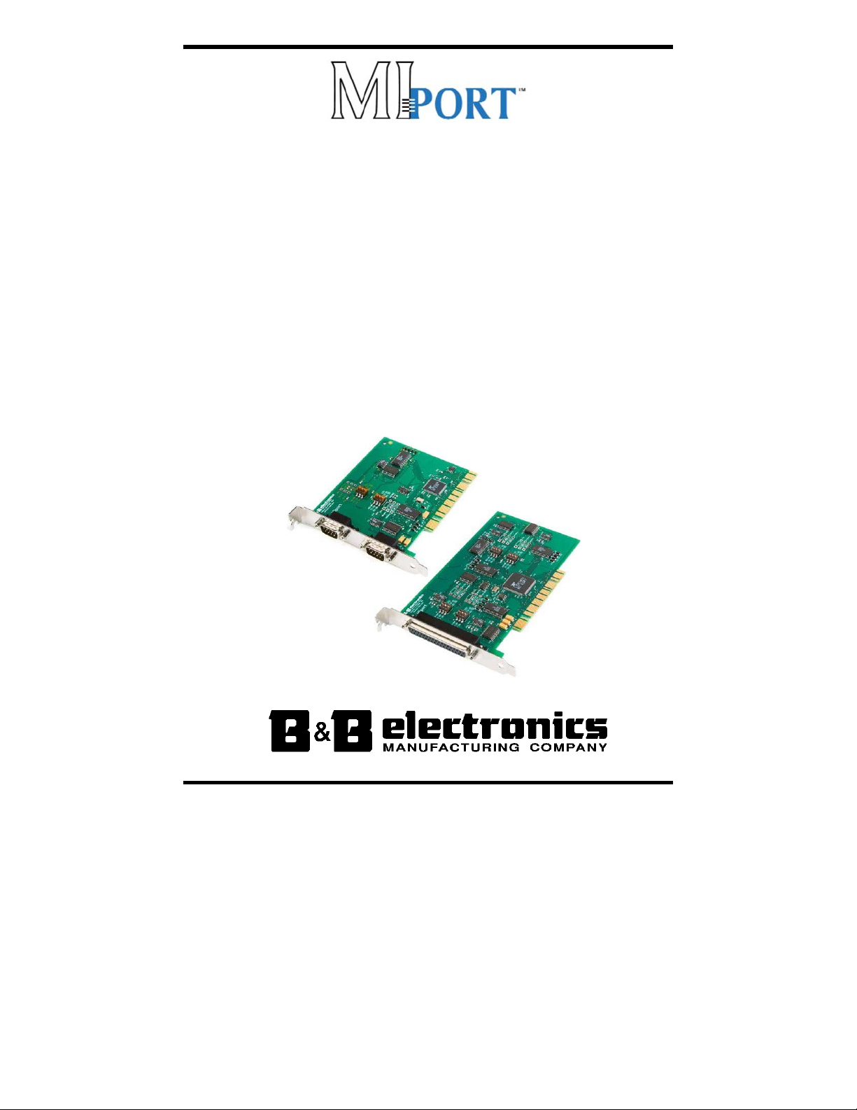
MMuullttii--IInntteerrffaacce
PPCCII BBuuss SSeerriiaall CCaarrdds
s
((RRSS--223322 // RRSS--442222 // RRSS--448855))
MMooddeellss 33PPCCIIUU22,, 33PPCCIIUU44,, 33PPCCIIUU88
)
((NNoonn--IIssoollaatteedd)
aanndd
MMooddeellss 33PPCCIIOOUU11,, 33PPCCIIOOUU22,, 33PPCCIIOOUU44
((IIssoollaatteedd))
Manual Documentation Number 3PCIoUx-1008
Page 2

International Headquarters
B&B Electronics Mfg. Co. Inc.
707 Dayton Road
Ottawa, IL 61350 USA
Phone (815) 433-5100 -- General Fax (815) 433-5105
Website: www.bb-elec.com
Sales e-mail: orders@bb-elec.com
Technical Support e-mail: support@bb.elec.com
European Headquarters
B&B Electronics
Westlink Commercial Park
Oranmore, Co. Galway, Ireland
Phone +353 91-792444 -- Fax +353 91-792445
Website: www.bb-europe.com
Sales e-mail: sales@bb-europe.com
Technical Support e-mail: support@bb-europe.com
© 2008 B&B Electronics – Revised February 2008
-- Fax (815) 433-5109
-- Fax (815) 433-5104
Manual Documentation Number 3PCIoUx-1008
B&B Electronics Mfg Co Inc – 707 Dayton Rd - PO Box 1040 - Ottawa IL 61350 - Ph 815-433-5100 - Fax 815-433-5104 – www.bb-elec.com
B&B Electronics Ltd – Westlink Commercial Park – Oranmore, Galway, Ireland – Ph +353 91-792444 – Fax +353 91-792445 – www.bb-europe.com
Page 3

CAUTION:
This is an Electrostatic Sensitive Device. Use ESD precautions for safe
handling.
Before removing the card from the anti-static protective packaging:
- Discharge any static electricity buildup on your body by touching a large
grounded metal surface or the metal chassis on equipment connected to earth
ground by a 3-wire power cord. Use of a grounding wrist strap is recommended.
- Avoid touching the gold connectors or other parts on the card except when
necessary to set the configuration DIP switches.
- Remove AC power from the computer before inserting the card
©
2008 B&B Electronics. No part of this publication may be reproduced or transmitted in any form or by any means, electronic or
mechanical, including photography, recording, or any information storage and retrieval system without written consent. Information
in this manual is subject to change without notice, and does not represent a commitment on the part of B&B Electronics.
B&B Electronics shall not be liable for incidental or consequential damages resulting from the furnishing, performance, or use of
this manual.
All brand names used in this manual are the registered trademarks of their respective owners. The use of trademarks or other
designations in this publication is for reference purposes only and does not constitute an endorsement by the trademark holder.
Manual Documentation Number 3PCIoUx-1008 Table of Contents i
Page 4

TTaabbllee ooff CCoonntteennttss
TABLE OF CONTENTS ...........................................................................................II
CHAPTER 1: GENERAL INFORMATION ........................................................... 1
INTRODUCTION ........................................................................................................... 1
FEATURES ................................................................................................................... 1
MIPORT MODELS AND FEATURES ............................................................................... 3
QUICK START GUIDE .................................................................................................. 5
SPECIFICATIONS .......................................................................................................... 7
CHAPTER 2: SERIAL CARD SETUP ..................................................................... 8
PRE-SETUP STEPS ....................................................................................................... 8
ESD Precautions .................................................................................................... 8
Initial Configuration .............................................................................................. 8
OVERVIEW OF OPERATIONAL MODES ......................................................................... 9
RS-232 Mode .......................................................................................................... 9
RS-422 Mode .......................................................................................................... 9
RS-485 Mode .......................................................................................................... 9
OPERATING MODE SELECTION ................................................................................. 10
Setting the DIP Switches on RS-232/422/485 Ports ............................................. 11
Setting the DIP Switches on RS-422/485 Only Ports ........................................... 12
INSTALLING THE SERIAL CARD ................................................................................. 14
CHAPTER 3: DRIVER SOFTWARE INSTALLATION ...................................... 15
INSTALLING WINDOWS VISTA DRIVER SOFTWARE ................................................... 15
Pre-Installation Steps ........................................................................................... 15
Using the Found New Hardware Wizard ............................................................. 16
INSTALLING WINDOWS XP PROFESSIONAL DRIVER SOFTWARE ............................... 17
Windows Settings ................................................................................................. 17
Pre-Installation Steps ........................................................................................... 17
Using the Found New Hardware Wizard ............................................................. 18
Checking the Driver Installation .......................................................................... 20
INSTALLING WINDOWS 2000 PROFESSIONAL DRIVER SOFTWARE ............................ 22
Windows Settings ................................................................................................. 22
Pre-Installation Steps ........................................................................................... 22
Using the Found New Hardware Wizard ............................................................. 23
Checking the Driver Installation .......................................................................... 27
INSTALLING WINDOWS 98 OR ME DRIVER SOFTWARE ............................................. 28
Windows Settings ................................................................................................. 28
Pre-Installation Steps ........................................................................................... 28
Using the Add New Hardware Wizard ................................................................. 29
Checking the Driver Installation .......................................................................... 32
ii Table of Contents Manual Documentation Number 3PCIoUx-1008
Page 5

INSTALLING WINDOWS NT DRIVER SOFTWARE ....................................................... 34
INSTALLING WINDOWS NT DRIVER SOFTWARE ....................................................... 34
Windows Settings ................................................................................................. 34
Pre-Installation Steps ........................................................................................... 34
Installing the Driver Software .............................................................................. 34
Configuring the Serial Ports ................................................................................ 37
CHAPTER 4: SETTING DRIVER OPTIONS ....................................................... 40
CONFIGURING PORT SETTINGS (DOES NOT APPLY TO WINDOWS NT.) ..................... 40
SETTING THE FIFO BUFFERS .................................................................................... 41
SETTING THE RTS CONTROL PARAMETER ................................................................ 42
SETTING THE HARDWARE HANDSHAKING LEVEL ..................................................... 42
CHANGING THE COM PORT NAME/NUMBER ............................................................ 42
CHAPTER 5: INSTALLING LINUX DRIVER SOFTWARE ............................. 44
INSTALLING MIPORT DRIVERS IN LINUX .................................................................. 44
Preparing the Linux Files .................................................................................... 44
Compiling the Driver ........................................................................................... 44
Installing the Driver ............................................................................................. 45
CHECKING THE DRIVER INSTALLATION .................................................................... 47
USING THE EXAR SERIAL GUI EXAMPLE APPLICATION ........................................... 48
Preparing the Example Application Files ............................................................ 48
Running the Exar Serial Test GUI ....................................................................... 48
Configuring Port Settings .................................................................................... 50
CHAPTER 6: REMOVING DRIVERS, PORTS AND CARDS............................ 51
REMOVING MIPORT CARDS FROM WIN98/ME/2000/2003 SERVER/XP/VISTA ......... 51
Uninstalling the MIport Card .............................................................................. 51
Uninstalling the COM ports ................................................................................. 51
Removing INF and PNF Driver Files .................................................................. 52
REMOVING MIPORT CARDS FROM WINDOWS NT ..................................................... 54
Uninstalling the MIport Card .............................................................................. 54
Uninstalling the Driver ........................................................................................ 54
CHAPTER 7: RS-232 CONNECTIONS/OPERATION ......................................... 55
RS-232 MODE .......................................................................................................... 55
RS-232 SIGNAL DESIGNATIONS AND DB-9 PINOUT ................................................. 55
RS-232 Signal Designations ................................................................................. 56
DTE AND DCE ......................................................................................................... 56
RS-232 SIGNAL LEVELS ........................................................................................... 57
HANDSHAKING ......................................................................................................... 57
RTS CONTROL IN RS-232 MODE ............................................................................. 57
CHAPTER 8: RS-422/485 CONNECTIONS/OPERATION ................................. 59
RS-422/485 MODE ................................................................................................... 59
Manual Documentation Number 3PCIoUx-1008 Table of Contents iii
Page 6

RS-422/485 SIGNAL DESIGNATIONS AND DB-9 PINOUT .......................................... 59
RS-422/485 Signal Designations ......................................................................... 60
RS-422/485 DIFFERENTIAL SIGNALS ........................................................................ 60
RS-422 OPERATION .................................................................................................. 61
RS-422 Limitations ............................................................................................... 61
RS-485 OPERATION .................................................................................................. 61
Send Data Control ............................................................................................... 62
RS-485 TERMINATION RESISTORS ............................................................................ 63
RS-485 NETWORK BIASING ...................................................................................... 63
2-WIRE RS-485 CONNECTIONS ................................................................................ 65
2-Wire RS-485 Mode: .......................................................................................... 65
4-WIRE RS-422 AND RS-485 CONNECTIONS ............................................................ 65
RS-422 Point to Point Connection ....................................................................... 65
RS-422 Point to Multipoints Connection ............................................................. 66
4-Wire RS-485 Connection .................................................................................. 66
CHAPTER 9: TROUBLESHOOTING MIPORT CARDS .................................... 68
STARTING UP ............................................................................................................ 68
CHECKING CONNECTIONS ......................................................................................... 68
RS-232/422/485 Operation .................................................................................. 68
RS-232 Operation ................................................................................................ 68
RS-422/485 Operation ......................................................................................... 69
CHECKING THE MIPORT CARD ................................................................................. 69
Support ................................................................................................................. 71
APPENDIX A: DIP SWITCH/MODE SETTINGS .................................................. 1
SETTING THE DIP SWITCHES ON RS-232/422/485 PORTS ........................................... 1
DIP Switch 1 (RS-232/422/485 ports) .................................................................... 1
DIP Switch 2 (RS-232/422/485 ports) .................................................................... 1
DIP Switch 3 (RS-232/422/485 ports) .................................................................... 2
SETTING THE DIP SWITCHES ON RS-422/485 ONLY PORTS ........................................ 2
APPENDIX B: CONNECTOR PINOUTS ............................................................... 1
RS-232 PINOUTS ........................................................................................................ 1
RS-422/485 PINOUTS ................................................................................................. 2
APPENDIX C: TROUBLESHOOTING WITH COMTEST ................................. 1
COMTEST FEATURES .................................................................................................. 1
INSTALLING COMTEST ............................................................................................... 2
LOOPBACK TESTING WITH COMTEST ......................................................................... 2
APPENDIX D: DECLARATION OF CONFORMITY STATEMENT ................ 5
iv Table of Contents Manual Documentation Number 3PCIoUx-1008
Page 7
General Information
Introduction
MIport PCI serial interface cards allow you to add RS-232, RS-422 and RS485 interfaces to Windows based computers equipped with a PCI bus.
Depending on your choice of card one, two or four optically isolated serial
ports, or two, four or eight non-isolated serial ports, can be added. MIport
PCI serial cards are Plug and Play compatible, which allows the Windows
Operating System and driver to set the addresses and IRQ used by the card.
CChhaapptteerr 11:: GGeenneerraall IInnffoorrmmaattiioonn
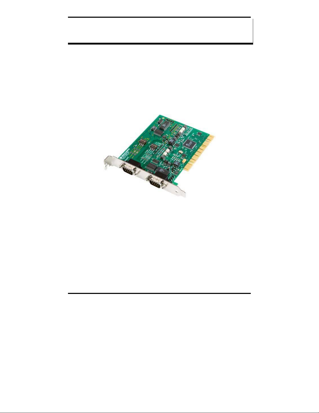
Figure 1. A 3PCIOU2 Optically Isolated Two-Port PCI Serial
Interface Card
Features
• Optically isolated or non-isolated models available
• Isolated models available in 1, 2 or 4 ports
• Non-isolated models available in 2, 4 or 8 ports
• 4 and 8 port models include fanout cables
• Plug & Play compatible – Windows sets addresses and IRQ used
• 5 volt and 3.3 volt PCI bus compatible
• PCI-X compatible
Manual Documentation Number 3PCIoUx-1008 Chapter 1 1
Page 8

General Information
• Conform to the PCI V2.3 Universal PCI specification
• RS-232/RS-422/RS-485 interfaces
• 2-wire or 4-wire RS-485 operation (half or full-duplex)
• Automatic Send Data Control for RS-485 operation
• Buffered high speed XR17D15x PCI Bus UARTs (16C550 compatible)
with 64 byte FIFOs for input/output with programmable trigger
thresholds
• Advanced driver function for COM port rename (Refer to Chapter 4)
• Supports baud rates up to 460.8 kbps
• Windows 98, ME, NT4.0, 2000, 2003 Server, XP, Vista and Linux 2.4
supported
2 Chapter 1 Manual Documentation Number 3PCIoUx-1008
Page 9
General Information
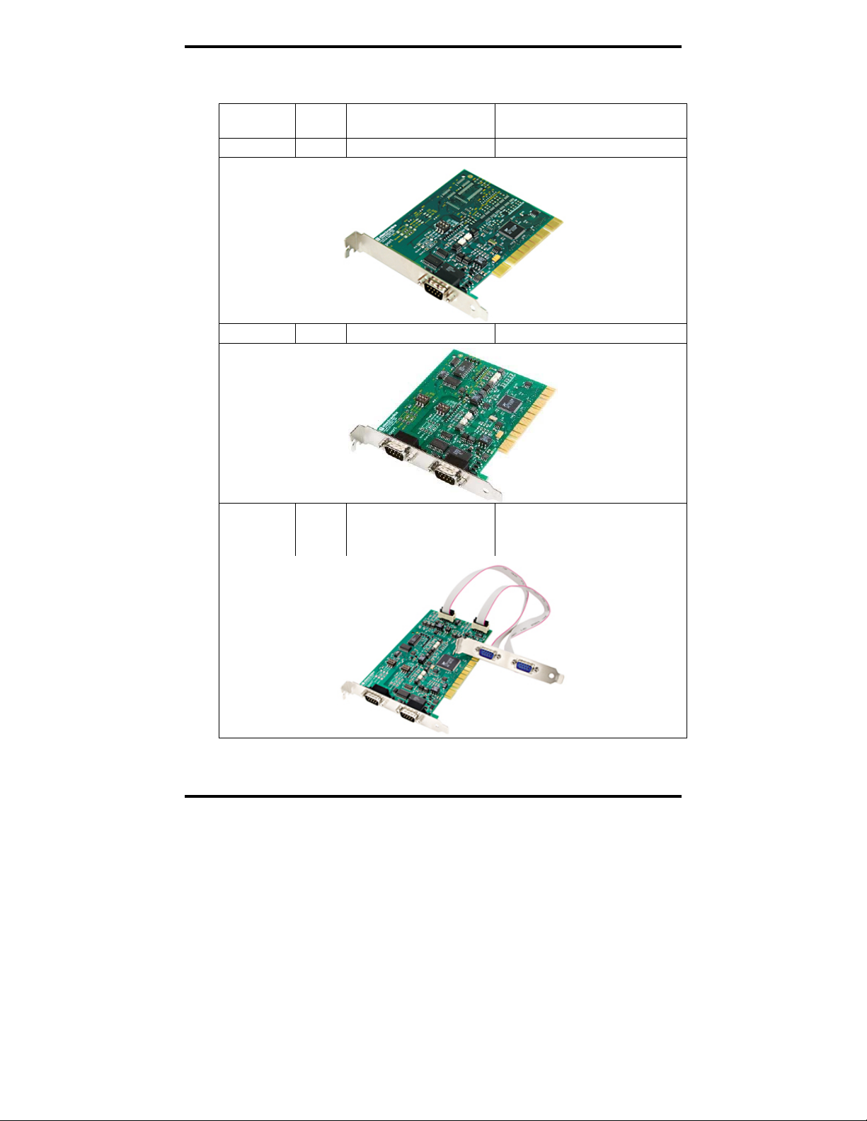
MIport Models and Features
Model
Number
3PCIOU1
3PCIOU2
3PCIOU4
Ports Interface Connectors
1 RS-232/422/485 DB-9 male
2 RS-232/422/485 DB-9 male
4 2 RS-232/422/485 ports
2 RS-422/485 ports
2 x DB-9 male use 2nd expansion
2 x DB-9 male
slot
Figure 2. MIport Optically Isolated PCI Cards
Manual Documentation Number 3PCIoUx-1008 Chapter 1 3
Page 10
General Information
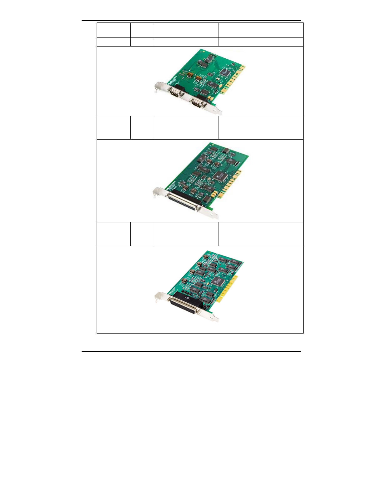
Model
Number
3PCIU2
3PCIU4
Ports Interface Connectors
2 RS-232/422/485 2 x DB-9 male
4 RS-232/422/485 DB-37 female
(plus DB-37 to 4x DB-9 male
cable)
3PCIU8
8 4 RS-232/422/485 ports
4 RS-232 ports
DB-78 female
(plus DB-78 to 8x DB-9 male
cable)
Figure 3. MIport Non-Isolated PCI Cards
4 Chapter 1 Manual Documentation Number 3PCIoUx-1008
Page 11

General Information
Quick Start Guide
CAUTION:
This is an Electrostatic Sensitive Device. Use ESD precautions for safe
handling.
Before removing the card from the anti-static protective packaging:
- Discharge any static electricity buildup on your body by touching a large
grounded metal surface or the metal chassis on equipment connected to earth
ground by a 3-wire power cord. Use of a grounding wrist strap is recommended.
- Avoid touching the gold connectors or other parts on the card except when
necessary to set the configuration DIP switches.
- Remove AC power from the computer before inserting the card
1. Determine the interface requirements of your application, including:
a. Interface standard(s) (RS-232, RS-422 or RS-485)
b. Data transmission mode (Two-wire or four-wire)
c. Cable lengths, connectors, pinouts
Note: For information on cables and pinouts refer to Chapter 5 (RS-
232) or Chapter 6 (RS-422/RS-485).
2. Set the operating mode DIP switches to configure the
communications interface for the required interface standard and
transmit/receive mode.
Note: Refer to the DIP switch table in Chapter 2.
3. Shut down your computer. (You may want to unplug the computer
power cord to prevent accidentally turning the computer on during
installation.)
4. Install the PCI card in your computer and replace the cover.
5. Connect the cable(s) from the card to your peripheral device (Cable
also can be connected/changed later.)
6. Power up the computer
7. Insert the driver disc into your CD-ROM drive
8. Wait until new hardware is detected.
9. Follow the instructions in the Add New Hardware Wizard. (This
varies depending on your operating system.)
Note: Refer to Chapter 3.
10. Check for new COM ports in Device Manager.
Manual Documentation Number 3PCIoUx-1008 Chapter 1 5
Page 12

General Information
11. Select the appropriate COM port, double-click and check properties.
12. Check and set up Port Settings
13. Under Advanced Settings, set Buffer, RTS Control and Hysteresis
14. If your card was not connected to a peripheral device in Step 5,
15. Use a communications test program (such as ComTest) to check
Level. Change the COM port name, if necessary.
make your connections now. (Powering down the computer while
making connections is recommended.)
communications between the computer and your peripheral device.
6 Chapter 1 Manual Documentation Number 3PCIoUx-1008
Page 13

General Information
Specifications
OS Supported
Bus
Slot
Baud Rates
UARTs
Character Length
Parity
Stop Bits
Optical Isolation
(3PCIOU1,
3PCIOU2,
3PCIOU4 only)
Connectors
Data Signals
Environmental
Dimensions
Accessories
Windows 98, ME, NT 4.0, 2000, 2003 Server, XP, Vista and Linux 2.4
PCI bus (33MHz/32-bit) PCI Bus specification
Requires one PCI slot (3.3V or 5V signaling)
Maximum: Up to 460.8 kbps (RS-232/422/485)
Typical: 75, 110, 134, 150, 300, 600, 1200, 1800, 2400, 4800,
7200, 9600, 14.4k, 19.2k, 38.4k, 57.6k, 115.2k,
230.4k, 460.8k
XR17D15x (16C550 compatible) with 64 byte FIFO buffers
5, 6, 7 or 8 bits
Even, odd, none, space or mark
1, 1.5 or 2
2000 VDC minimum on all lines
Ports are isolated from the PC power and ground, as well as other ports
on the same card.
3PCIOU1: 1 – DB-9 male
3PCIOU2: 2 – DB-9 male
3PCIOU4: 2 – DB-9 male (RS-232/422/485 ports)
nd
2 – DB-9 male via ribbon cable on 2
expansion slot
bracket (RS-422/485 ports)
3PCIU2: 2 – DB-9 male
3PCIU4: 1 – DB-37 female with DB-37 to 4 x DB-9 male
cable
3PCIU8: 1 - DB-78 female with DB-78 to 8 x DB-9 male
cable (4 x RS-232/422/485 and 4 x RS-232)
RS-232: TD, RD, RTS, CTS, DTR, DSR, DCD, RI and GND
(TD, RD, RTS, CTS, GND only on 3PCIOU4)
RS-422: TD(A)-, TD(B)+, RD(A)-, RD(B)+ and GND
RS-485: Data(A)-, Data(B)+ and GND
Operating temperature range: 0º to 50ºC minimum
Operating humidity: 5% to 95%, non-condensing
4.8 x 3.8 in (12.2 x 9.6 cm) card edge
(Mounting bracket, 1.2 x 12.1 x 0.9 cm)
Software: Driver CD-ROM disc for Windows 98, ME, NT,
4.0, 2000, 2003 Server, XP, Vista, and Linux 2.4
Manual: Instruction Manual Contained on CD ROM
Figure 4. MIport Serial Card Specifications
Manual Documentation Number 3PCIoUx-1008 Chapter 1 7
Page 14
Serial Card Setup
CChhaapptteerr 22:: SSeerriiaall CCaarrdd SSeettuupp
The following Serial Card Setup section applies to the following PCI cards:
• 3PCIOU1 one port optically isolated PCI serial card
• 3PCIOU2 two port optically isolated PCI serial card
• 3PCIOU4 four port optically isolated PCI serial card
• 3PCIU2 two port non-isolated PCI serial card
• 3PCIU4 four port non-isolated PCI serial card
• 3PCIU8 eight port non-isolated PCI serial card
Any deviations from the procedure for specific models are noted.
Pre-Setup Steps
Your serial card has been tested for proper operation before packaging and
shipping. It should be in perfect mechanical and electrical condition upon receipt.
ESD Precautions
To ensure a successful installation and setup it is important that you follow the
standard ESD precautions outlined below:
CAUTION:
This is an Electrostatic Sensitive Device. Use ESD precautions for safe
handling.
Before removing the card from the anti-static protective packaging:
- Discharge any static electricity buildup on your body by touching a large
grounded metal surface or the metal chassis on equipment connected to earth
ground by a 3-wire power cord. Use of a grounding wrist strap is recommended.
- Avoid touching the gold connectors or other parts on the card except when
necessary to set the configuration DIP switches.
- Remove AC power from the computer before inserting the card
Initial Configuration
The ports in your MIport card are normally pre-configured for RS-232
operation. To ensure the card is configured correctly for your desired operating
mode, you will have to check and/or set the three operating mode DIP switches
on the card. If you are configuring for RS-485 Mode you also may have to set
up the RTS Control parameter in the device driver.
Note: Refer to Chapter 4 for information on Setting Driver Options.
8 Chapter 2 Manual Documentation Number 3PCIoUx-1008
Page 15

Serial Card Setup
Overview of Operational Modes
RS-232 Mode
In RS-232 Mode MIport serial ports function as buffered standard PC serial
ports and operate as DTEs (Data Terminal Equipment). RS-232 interfaces are
commonly used for communications with modems, serial printers, and
computer-controlled devices such as security equipment, bar code scanners
and point-of-sale devices.
For most MIport models, RS-232 Mode supports eight single-ended signal
lines and signal ground (GND) including transmit (TD), receive (RD) and six
hardware handshake lines (DTR, DSR, RTS, CTS, DCD, RI). The only
exception to this is the MIport Model 3PCIOU4 card, which supports TD,
RD, RTS, CTS and GND.
RS-422 Mode
In RS-422 mode MIport serial ports provide two sets of differential signal
pairs (TD and RD) and signal ground for each port. The RS-422 standard
uses balanced differential drivers and receivers for each signal. This
facilitates greater communication distances than unbalanced systems such as
RS-232. In RS-422 mode the transmitter and receiver are always enabled (TX
ON, RX ON).
RS-422 operation is suitable for interconnecting a computer and one device
for full duplex (point-to-point) bi-directional communication, or a computer
and several devices for unidirectional (point-to-multipoints) communication.
RS-422 interfaces are commonly used for video editing/control, camera
control, electronic signage, television studio/satellite dish control,
performance lighting and audio equipment control.
RS-485 Mode
In RS-485 Mode MIport cards provide RS-485 interfaces which operate with
the same signals and signal levels as RS-422. RS-485 interfaces differ from
RS-422 in that they allow multiple devices to share the same communication
link using half duplex (2-wire) or full duplex (4-wire) connections. Since it is
possible to have more than one transmitter connected to the media,
transmitters must be enabled only while sending data, and tri-stated at all
other times so other devices can use the wire pair. MIport cards automatically
enable the transmitter at the appropriate time using Automatic Send Data
Control, based on the contents of the output buffer. When the buffer has data
to send, the transmitter is enabled (TX SD). When all data in the buffer has
been sent, the transmitter is disabled and tri-stated to a high impedance state.
Manual Documentation Number 3PCIoUx-1008 Chapter 2 9
Page 16

Serial Card Setup
In half-duplex operation, the receiver is disabled during transmit (RX ),
and enabled when not transmitting. In full-duplex operation the receiver is
always enabled (RX ON). Since RS-485 transmitters are tri-stated when not
transmitting, the receive inputs must be biased to ensure the media floats in
the Mark state so that the first Space state is detected correctly at the start of
the next transmission.
These serial cards incorporate the necessary biasing to accommodate up to 32
standard nodes. (Typical input resistance (Rin) for each load is 12kΩ).
Provisions are made for custom biasing and/or termination.
Note: For more information on RS-485 Mode refer to Chapter 6
Operating Mode Selection
The hardware address and IRQ for the serial card is set by the Windows
Operating System using driver information files and the Plug and Play OS.
The Operating Mode is set using DIP switches, Device Manager Driver
Settings and by your cable connections and software. Each port on a MIport
card has an associated DIP switch to set its operating mode. The port number
associated with the DIP switch is clearly silk screened on the printed circuit
board.
Note: Refer to Appendix x for DIP switch locations on various MIport
cards.
10 Chapter 2 Manual Documentation Number 3PCIoUx-1008
Page 17
Serial Card Setup
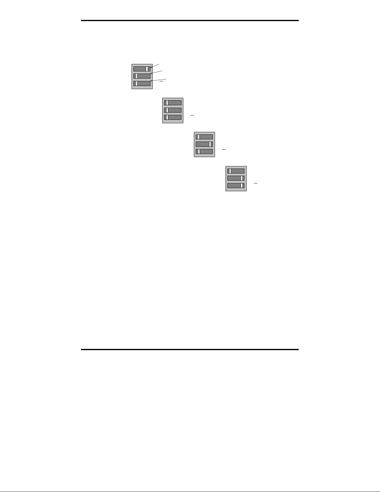
Setting the DIP Switches on RS-232/422/485 Ports
Set the DIP switches to configure the desired operating mode as follows:
422/485
TX On
RX On
Switch 1
232
TX SD
RX SD
Switch 2
Switch 3
RS-232 Mode
422/485
TX On
RX On
232
TX SD
RX SD
RS-422 Mode
422/485
TX On
RX On
232
TX SD
RX SD
4-wire RS-485 Mode
422/485
TX On
RX On
2-wire RS-485 Mode
232
TX SD
RX SD
Figure 5. RS-232/422/485 DIP Switch Settings.
DIP Switch 1 (RS-232/422/485 ports)
The top DIP switch (1) configures the port for RS-232 or RS-422/485
operation. This switch is the only one that is required to be set for RS-232
operation. The positions of switches 2 and 3 do not matter when switch 1 is
set for RS-232 operation.
DIP Switch 2 (RS-232/422/485 ports)
The middle DIP switch (2) configures the port for RS-485 or RS-422
operation. For RS-422 operation (which uses two wire pairs and sends pointto-point or point-to-multipoints) the transmitter can be enabled all the time.
Placing the middle DIP switch in the TX ON position accomplishes this.
For RS-485 operation the middle DIP switch is placed in the TX SD position.
In this position the transmitter is only enabled when data is being sent. The
transmitter is tri-stated when not sending data, allowing other transmitters on
the communications line to transmit without interference.
Manual Documentation Number 3PCIoUx-1008 Chapter 2 11
Page 18
Serial Card Setup
DIP Switch 3 (RS-232/422/485 ports)
The bottom DIP switch (3) configures the port for half-duplex (two-wire)
RS-485 operation or full-duplex (four wire) RS-422/RS-485 operation.
Placing the bottom DIP switch in the RX ON position configures the port for
four wire operation. In this mode the receiver is continuously enabled,
allowing it to receive all data on the communications line. Since the
transmitter sends data on the other wire pair the port does not receive its own
transmissions.
Placing the bottom DIP switch in the RX
position configures the port for
two wire operation. In this mode the transmitter and receiver are connected to
the same wire pair. The receiver is disabled when its transmitter is sending,
preventing the port from receiving its own data.
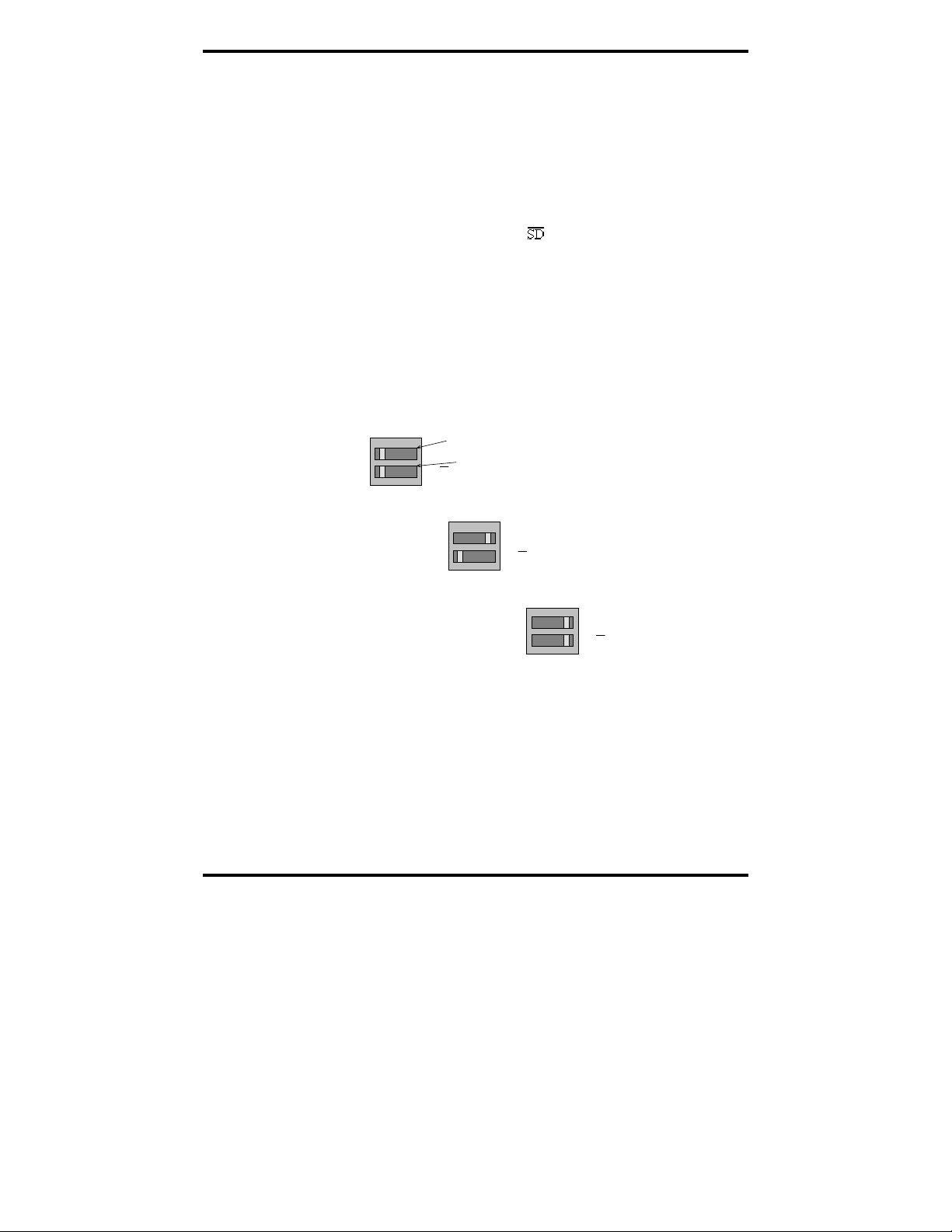
Setting the DIP Switches on RS-422/485 Only Ports
The 3PCIOU4 MIport card provides a combination of RS-232/422/485 and
RS-422/485 only ports. Ports that do not include RS-232 operation use
double DIP switches rather than triple DIP switches. These DIP switches
operate the same as the two bottom DIP switches in the RS232/422/485 ports
TX On
RX On
RS-422 Mode
Figure 6. RS-422/485 only DIP Switch Settings
Switch 1
TX SD
Switch 2
RX SD
TX On
RX On
4-wire RS-485 Mode
TX SD
RX SD
TX On
RX On
2-wire RS-485 Mode
TX SD
RX SD
DIP Switch 1 (RS-422/485 only)
The top DIP switch (1) configures the port for RS-485 or RS-422 operation.
For RS-422 operation (which uses two wire pairs and sends point-to-point or
point-to-multipoints) the transmitter can be enabled all the time. Placing the
middle DIP switch in the TX ON position accomplishes this.
12 Chapter 2 Manual Documentation Number 3PCIoUx-1008
Page 19

Serial Card Setup
For RS-485 operation the middle DIP switch is placed in the TX SD position.
In this position the transmitter is only enabled when data is being sent. The
transmitter is tri-stated when not sending data, allowing other transmitters on
the communications line to transmit without interference.
DIP Switch 2 (RS-422/485 only)
The bottom DIP switch (2) configures the port for half-duplex (two-wire)
RS-485 operation or full-duplex (four wire) RS-422/RS-485 operation.
Placing the bottom DIP switch in the RX ON position configures the port for
four wire operation. In this mode the port’s receiver is continuously enabled,
allowing it to receive all data on the communications line. Since the port’s
transmitter sends data on the other wire pair the port does not receive its own
transmissions.
Placing the bottom DIP switch in the RX
position configures the port for
two wire operation. In this mode the port’s transmitter and receiver are
connected to the same wire pair. The receiver is disabled when its transmitter
is sending, preventing the port from receiving its own data.
Manual Documentation Number 3PCIoUx-1008 Chapter 2 13
Page 20

Serial Card Setup
Installing the Serial Card
CAUTION:
This is an Electrostatic Sensitive Device. Use ESD precautions for safe
handling.
Before removing the card from the anti-static protective packaging:
- Discharge any static electricity buildup on your body by touching a large
grounded metal surface or the metal chassis on equipment connected to earth
ground by a 3-wire power cord. Use of a grounding wrist strap is recommended.
- Avoid touching the gold connectors or other parts on the card except when
necessary to set the configuration DIP switches.
- Remove AC power from the computer before inserting the card
1. Shut down your computer.
2. Unplug the power cord to remove power to prevent accidentally
turning on the computer during installation.
3. Remove the cover of the computer.
4. Locate an empty PCI expansion slot.
5. Remove the expansion slot cover. Save the retaining screw.
6. Ground yourself to the computer chassis before and while inserting
the card.
7. Install the card into the unused slot. Be certain that the card is
inserted completely (fully seated) in the slot.
8. Secure the card with the mounting screw from Step 5.
9. Replace the cover; plug in the power cord.
10. Connect your cables.
11. Power up the system.
12. Install the drivers as described in Chapter 3.
14 Chapter 2 Manual Documentation Number 3PCIoUx-1008
Page 21

Driver Software Installation
CChhaapptteerr 33:: DDrriivveerr SSooffttwwaarree IInnssttaallllaattiioonn
Installing Windows Vista Driver Software
Installation of the MIport driver software on Windows Vista is a three-step
process:
1. Windows Vista searches and identifies new hardware that has been
installed.
2. You use the Found New Hardware Wizard to install the driver
software for the card.
3. You use the Found New Hardware Wizard to install the software for
each port on the card.
There are several possible methods for installing the software. The procedure
outlined here is recommended for most situations.
Note: If at some point in the future, you want to update these drivers,
remove the old drivers before installing the new version. Refer to
Chapter 6 for driver removal procedures.
Pre-Installation Steps
1. Configure the port(s) on the card for the desired mode (RS-232, RS-
422 or RS-485) using the three DIP switches on the card.
2. If configuring for RS-422 or RS-485 Modes, and bias or termination
resistors are needed, add them at this time.
Note: Refer to Chapter 2 of information on DIP switch settings and
bias/termination resistors.
3. Install the card in the slot. Use appropriate ESD handling
precautions.
4. Power up the computer
5. Insert your driver disc in the CD-ROM drive.
Manual Documentation Number 3PCIoUx-1008 Chapter 3 15
Page 22

Driver Software Installation
Using the Found New Hardware Wizard
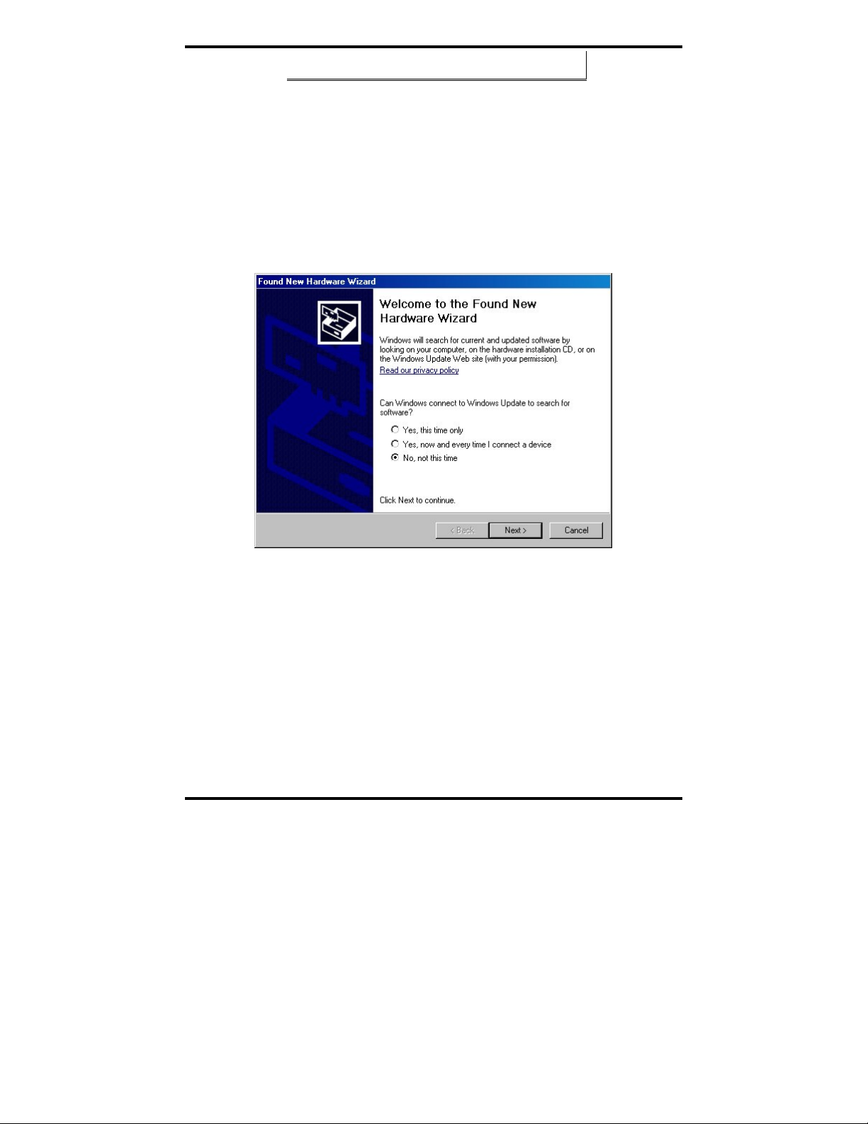
Windows will detect the PCI card and start the Found New Hardware
Wizard
to begin the driver installation. The following dialog box will appear:
Drive software (on CD-ROM) is provided with your MIport card. Do not
connect to Windows Update to search for software.
6. Select No, not at this time and click Next.
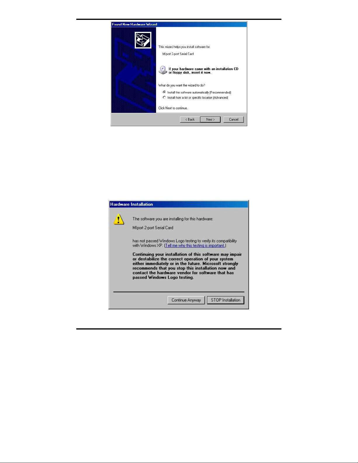
PCI Card Software Installation
Once the new hardware has been detected, the wizard will proceed to install
the software for the card. The following dialog box will appear:
7. To begin the installation of the software for the PCI card, click
Install the software automatically. Click Next.
Windows will find the appropriate files on the CD, then display a
dialog box concerning Window Logo testing for Vista. This feature
of Vista simply indicates that these drivers have not yet undergone
the Microsoft testing procedure required to use the Windows Vista
Logo on the packaging. Diver compatibility is not affected.
8. Click Continue Anyway.
A dialog box will appear indicating the software installation is
proceeding.
9. When the Completing the Found New Hardware Wizard dialog
appears, click Finish.
Port Driver Installation
The Welcome to the Found New Hardware Wizard will appear again, indicating it has
detected a port on the PCI card. Repeat the steps above to install the port driver
software.
If the cared you are installing has more than one port, Windows Vista will find each
port in sequence and re-launch the Found New Hardware Wizard for each port.
Repeat the previous steps for each port.
Checking the Driver Installation
You may want to check to verify that the new B&B COM ports are now available.
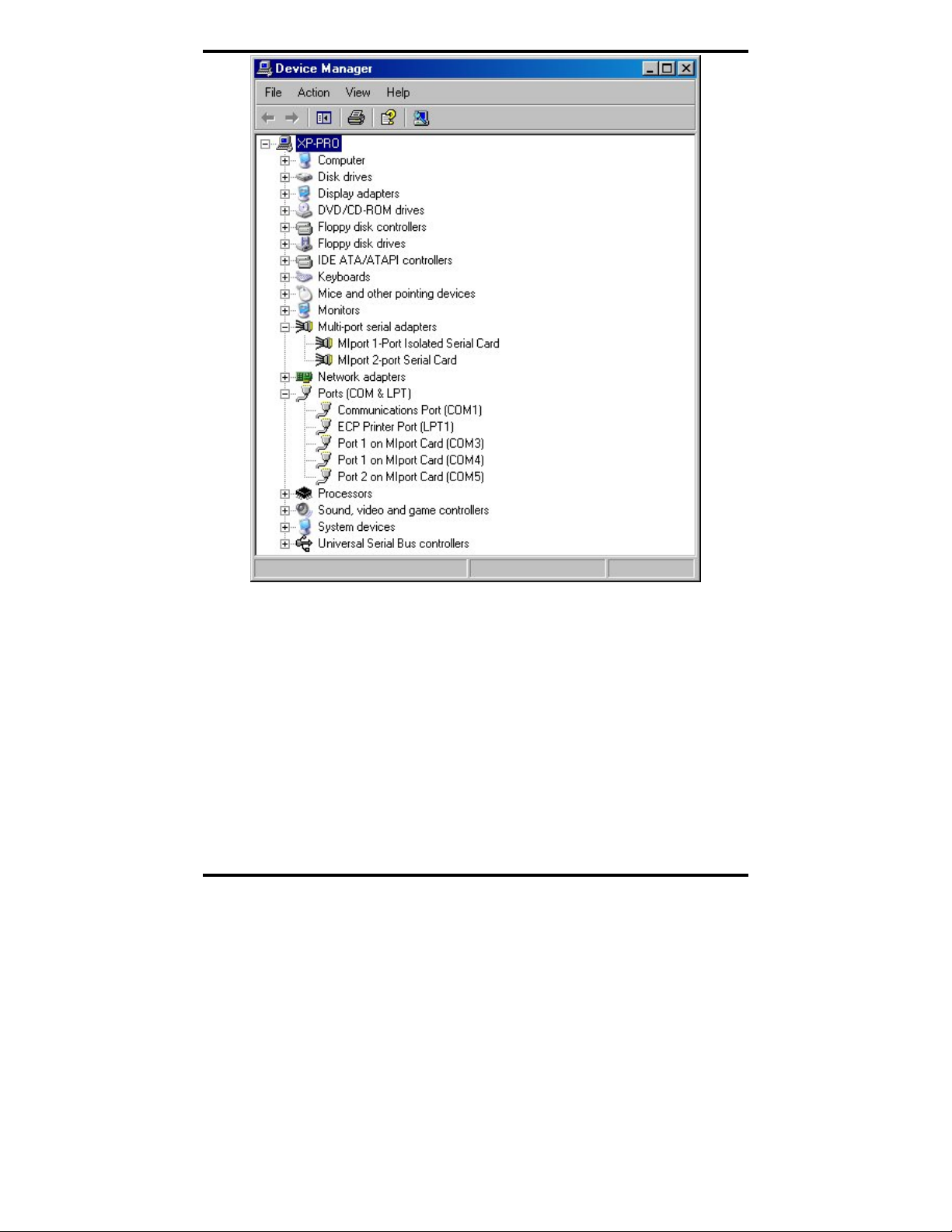
1. From the Widows Desktop, click Start → Control Panel
→System and Maintenance → Device Manager
2. In the Device Manager, click Multi-port serial adapters.
16 Chapter 3 Manual Documentation Number 3PCIoUx-1008
Page 23

Driver Software Installation
All serial adapter cards should appear in the list. Additional
information about the cards can be obtained by double-clicking the
name of the card.
3. Click Ports (COM & LPT)
All installed ports should appear in the list. The COM port number
assigned to each port will be shown.
Installing Windows XP Professional Driver Software
Installation of the MIport driver software on Windows XP Professional is a
three-step process:
1. Windows XP searches for and identifies new hardware that has
been installed.
2. You use the Found New Hardware Wizard to install the driver
software for the card.
3. You use the Found New Hardware Wizard to install the software for
each port on the card.
There are several possible methods for installing the software. The procedure
outlined here is recommended for most situations.
Note: If at some point in the future, you want to update these drivers,
remove the old drivers before installing the new version. Refer to
Chapter 6 for driver removal procedures.
Windows Settings
Windows Classic settings are used in the following screenshots. To configure
Windows XP for Windows Classic settings, position the mouse pointer over
the
Taskbar (at the bottom of the Desktop), then right click. On the menu
that appears, click Properties. The Taskbar and Start Menu Properties
dialog will appear. Click the Start Menu tab, then click Classic Start Menu.
Click
OK.
Pre-Installation Steps
4. Configure the port(s) on the card for the desired mode (RS-232, RS-
422 or RS-485) using the three DIP switches on the card.
5. If configuring for RS-422 or RS-485 Modes, and bias or termination
resistors are needed, add them at this time.
Manual Documentation Number 3PCIoUx-1008 Chapter 3 17
Page 24
Driver Software Installation
Note: Refer to Chapter 2 of information on DIP switch settings and
bias/termination resistors.
6. Install the card in the slot. Use appropriate ESD handling
precautions.
7. Power up the computer
8. Insert your driver disc in the CD-ROM drive.
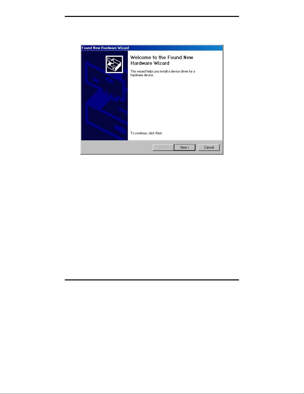
Using the Found New Hardware Wizard
Windows will detect the PCI card and start the Found New Hardware
Wizard to begin the driver installation. The following dialog box will appear:
Figure 7. The XP Found New Hardware Wizard
Driver software (on CD-ROM) is provided with your MIport card.
Do not connect to Windows Update to search for software.
9. Select
PCI Card Software Installation
No, not this time and click Next.
Once the new hardware has been detected, the wizard will proceed to install
the software for the card. The following dialog box will appear:
18 Chapter 3 Manual Documentation Number 3PCIoUx-1008
Page 25
Driver Software Installation
Figure 8. The “Install the Card Software Automatically” Dialog
10. To begin the installation of the software for the PCI card, click
Install the software automatically. Click Next.
Windows will find the appropriate files on the CD, then display a
dialog box concerning Windows Logo testing for XP. This feature
of XP simply indicates that these drivers have not yet undergone the
Microsoft testing procedures required to use the Windows XP Logo
on the packaging. Driver compatibility is not affected.
Figure 9. Windows Logo Testing Screen
Manual Documentation Number 3PCIoUx-1008 Chapter 3 19
Page 26

Driver Software Installation
11. Click Continue Anyway.
A dialog box will appear indicating the software installation is
proceeding.
12. When the
Completing the Found New Hardware Wizard dialog
appears, click Finish.
Port Driver Installation
The Welcome to the Found New Hardware Wizard will appear again,
indicating it has detected a port on the PCI card. Repeat the steps above to
install the port driver software.
If the card you are installing has more than one port, Windows XP will find
each port in sequence and re-launch the
each port. Repeat the previous steps for each port.
Checking the Driver Installation
You may want to check to verify that the new B&B COM ports are now
available.
1. From the Windows Desktop, click
Panel → System
2. On the
System Properties dialog box, click the Hardware tab, then
click the Device Manager button. The Device Manager window
will appear:
Found New Hardware Wizard for
Start → Settings → Control
20 Chapter 3 Manual Documentation Number 3PCIoUx-1008
Page 27
Driver Software Installation
Figure 10. The Device Manager Window
3. In the Device Manager, click Multi-port serial adapters.
All serial adapter cards should appear in the list. Additional
information about the cards can be obtained by double-clicking the
name of the card.
4. Click
Ports (COM & LPT)
All installed ports should appear in the list. The COM port number assigned
to each port will be shown.
Manual Documentation Number 3PCIoUx-1008 Chapter 3 21
Page 28

Driver Software Installation
Installing Windows 2000 Professional Driver
Software
Installation of the MIport driver software on Windows 2000 Professional is a
three-step process:
1. Windows searches for and identifies new hardware that has been
installed.
2. You use the Found New Hardware Wizard to install the driver
software for the card.
3. You use the Found New Hardware Wizard to install the software for
each port on the card.
There are several possible methods for installing the software. The procedure
outlined here is recommended for most situations.
Note: If at some point in the future, you want to update these drivers,
remove the old drivers before installing the new version. Refer to
Chapter 6 for driver removal procedures.
Windows Settings
Windows Classic settings are used in the following screenshots. To configure
Windows for Windows Classic settings, position the mouse pointer over the
Taskbar (at the bottom of the Desktop), then right click. On the menu that
appears, click Properties. The Taskbar and Start Menu Properties dialog will
appear. Click the
Start Menu tab, then click Classic Start Menu. Click OK.
Pre-Installation Steps
4. Configure the port(s) on the card for the desired mode (RS-232, RS-
422 or RS-485) using the three DIP switches on the card.
5. If configuring for RS-422 or RS-485 Modes, and bias or termination
resistors are needed, add them at this time.
Note: Refer to Chapter 2 of information on DIP switch settings and
bias/termination resistors.
6. Install the card in the slot. Use appropriate ESD handling
precautions.
7. Make sure PnP OS is set in the BIOS.
8. Power up the computer
9. Insert your driver disc in the CD-ROM drive.
22 Chapter 3 Manual Documentation Number 3PCIoUx-1008
Page 29
Driver Software Installation
Using the Found New Hardware Wizard
Windows will detect the PCI card and start the Found New Hardware
Wizard
to begin the driver installation. The following dialog box will appear:
Figure 11. The Windows 2000 Add New Hardware Wizard
The driver installation goes through several steps, after finding the
driver files. The first part installs the driver for the card, then after
Finish, the second part installs the serial driver for the COM port.
Do not remove the CD until completed.
10. Click Next.
PCI Card Software Installation
Once the new hardware has been detected, the wizard will proceed to install
the software for the card. The following dialog box will appear:
Manual Documentation Number 3PCIoUx-1008 Chapter 3 23
Page 30

Driver Software Installation
Figure 12. The “What do you want Windows to do?” dialog
11. To begin the installation of the software for the PCI card, click
Search for a suitable driver for my device, then click Next.
Figure 13. The “Windows will search for new driver” dialog
12. Select CD-ROM Drive, then click Next.
24 Chapter 3 Manual Documentation Number 3PCIoUx-1008
Page 31
Driver Software Installation
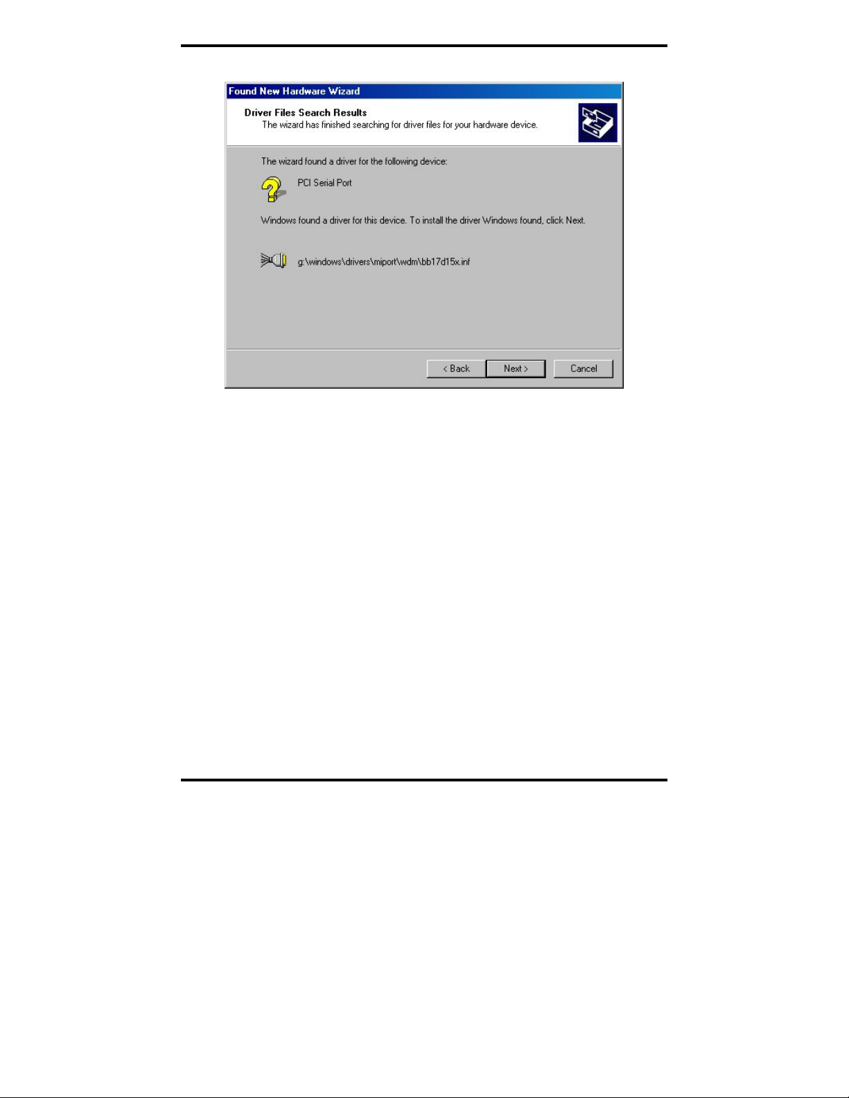
Windows will find the appropriate files on the CD.
Figure 14. The “Windows driver file search for the device” dialog
13. To begin the installation of the software for the PCI card, click
Next.
Windows will display the
Digital Signature Not Found dialog box.
This feature simply indicates that these drivers have not yet
undergone the Microsoft testing procedures required to use the
Windows logo on the packaging. Driver compatibility is not
affected.
Manual Documentation Number 3PCIoUx-1008 Chapter 3 25
Page 32

Driver Software Installation
Figure 15. The Digital Signature Not Found Dialog
14. Click Yes
A dialog box will appear indicating the software installation is
proceeding.
15. When the
Completing the Found New Hardware Wizard dialog
appears, click Finish.
Port Driver Installation
The Add New Hardware Wizard will appear again, indicating it has detected
a port on the PCI card. Repeat the steps above to install the port driver
software.
If the card you are installing has more than one port, Windows will find each
port in sequence and re-launch the
Found New Hardware Wizard for each
port. Repeat the previous steps for each port.
26 Chapter 3 Manual Documentation Number 3PCIoUx-1008
Page 33

Driver Software Installation
Checking the Driver Installation
You may want to check to verify that the new B&B COM ports are now
available.
1. From the
Panel → System
2. On the
Windows Desktop, click Start → Settings → Control
System Properties dialog box, click the Hardware tab, then
click the Device Manager button. The Device Manager window
will appear:
Figure 16. System Properties Screen
3. In the Device Manager, click Multi-port serial adapters
All serial adapter cards should appear in the list. Additional
information about the cards can be obtained by double-clicking the
name of the card.
4. Click
Ports (COM & LPT)
All installed ports should appear in the list. The COM port number
assigned to each port will be shown.
Manual Documentation Number 3PCIoUx-1008 Chapter 3 27
Page 34

Driver Software Installation
Installing Windows 98 or ME Driver Software
Installation of the MIport driver software on Windows 98 is a three-step
process:
1. Windows searches for and identifies new hardware that has been
installed.
2. You use the Found New Hardware Wizard to install the driver
software for the card.
3. You use the Found New Hardware Wizard to install the software for
each port on the card.
There are several possible methods for installing the software. The procedure
outlined here is recommended for most situations.
Note: If at some point in the future, you want to update these drivers,
remove the old drivers before installing the new version. Refer to
Chapter 6 for driver removal procedures.
Windows Settings
Windows Classic settings are used in the following screenshots. To configure
Windows for Windows Classic settings, position the mouse pointer over the
Taskbar (at the bottom of the Desktop), then right click. On the menu that
appears, click
will appear. Click the Start Menu tab, then click Classic Start Menu. Click
OK.
Properties. The Taskbar and Start Menu Properties dialog
Pre-Installation Steps
1. Configure the port(s) on the card for the desired mode (RS-232, RS-
422 or RS-485) using the three DIP switches on the card.
2. If configuring for RS-422 or RS-485 Modes, and bias or termination
resistors are needed, add them at this time.
Note: Refer to Chapter 2 of information on DIP switch settings and
bias/termination resistors.
3. Install the card in the slot. Use appropriate ESD handling
precautions.
4. Make sure PnP OS is set in the BIOS.
5. Power up the computer
6. Insert your driver disc in the CD-ROM drive.
28 Chapter 3 Manual Documentation Number 3PCIoUx-1008
Page 35

Driver Software Installation
Using the Add New Hardware Wizard
Windows will detect the PCI card and start the Add New Hardware Wizard
to begin the driver installation. The following dialog box will appear:
Figure 17. The Add New Hardware Wizard dialog
The driver installation goes through several steps, after finding the
driver files. The first part installs the driver for the card, then after
Finish, the second part installs the serial driver for the COM port.
Do not remove the CD until completed.
7. Click Next.
PCI Card Software Installation
Once the new hardware has been detected, the wizard will proceed to install
the software for the card. The following dialog box will appear:
Manual Documentation Number 3PCIoUx-1008 Chapter 3 29
Page 36

Driver Software Installation
Figure 18. The “What do you want Windows to do?” dialog
8. To begin the installation of the software for the PCI card, click
Search for the best driver for your device, then click Next.
Figure 19. The “Windows will search for new drivers” dialog
30 Chapter 3 Manual Documentation Number 3PCIoUx-1008
Page 37

Driver Software Installation
9. Select “Specify a location” and choose the
E:\ Windows\Drivers\MIport\98_ME folder.
NOTE: In Windows ME you will need to select the Driver from this folder:
E:\ Windows\Drivers\MIport\98_ME
Windows will find the appropriate files on the CD.
Figure 20. The “Windows driver file search for the device” dialog
10. Click Next.
Figure 21. The “Windows has finished installing” dialog
Manual Documentation Number 3PCIoUx-1008 Chapter 3 31
Page 38

Driver Software Installation
11. Click Finish. Installation will complete automatically.
Port Driver Installation
The Add New Hardware Wizard will appear again, indicating it has detected
a port on the PCI card. Repeat the steps above to install the port driver
software.
If the card you are installing has more than one port, Windows will find each
port in sequence and re-launch the
port. Repeat the previous steps for each port.
Checking the Driver Installation
You may want to check to verify that the new B&B COM ports are now
available.
1. From the Windows Desktop, click Start → Settings → Control
Panel → System
Found New Hardware Wizard for each
2. On the
System Properties dialog box, click the Hardware tab, then
click the Device Manager button. The Device Manager window
will appear:
32 Chapter 3 Manual Documentation Number 3PCIoUx-1008
Page 39

Driver Software Installation
Figure 22. System Properties Screen
3. In the
Device Manager, click Multiport Serial Cards
All serial adapter cards should appear in the list. Additional
information about the cards can be obtained by double-clicking the
name of the card.
4. Click
Ports (COM & LPT)
All installed ports should appear in the list. The COM port number
assigned to each port will be shown.
Manual Documentation Number 3PCIoUx-1008 Chapter 3 33
Page 40

Driver Software Installation
Installing Windows NT Driver Software
Installation of the MIport driver software on Windows NT is a two-step process:
1. Installing the driver software.
2. Configuring the ports
Note: If at some point in the future, you want to update these drivers,
remove the old drivers before installing the new version. Refer to
Chapter 6 for driver removal procedures.
Windows Settings
Windows Standard settings are used in the following screenshots. To
configure Windows NT for Windows Standard settings, open the Control
Panel
and double-click the Display icon. Click the Appearance tab and
select Windows Standard under Scheme, then click OK.
Pre-Installation Steps
1. Configure the port(s) on the card for the desired mode (RS-232, RS-
422 or RS-485) using the three DIP switches on the card.
2. If configuring for RS-422 or RS-485 Modes, and bias or termination
resistors are needed, add them at this time.
Note: Refer to Chapter 2 of information on DIP switch settings and
bias/termination resistors.
3. Install the card in the slot. Use appropriate ESD handling
precautions.
4. Power up the computer and login as the Administrator, or as a user
that is a member of the Administrators group.
5. Insert your driver disc in the CD-ROM drive.
Installing the Driver Software
The driver software only has to be installed once regardless of how many
MIport cards and/or ports are added to the system. If the driver software
already has been installed you can go directly to
Ports later in this section.
1. Using
Windows NT Explorer find the NT install.exe file on the
MIport installation CD. The file is located on the CD-ROM at:
E:\Windows\Drivers\MIport\NT4
34 Chapter 3 Manual Documentation Number 3PCIoUx-1008
Configuring the Serial
Page 41

Driver Software Installation
Figure 23. The Install.exe file in Windows NT Explorer
2. Double-click the install.exe file. The MIport Driver v1.0.0 for
Windows NT 4.0 Installation Welcome dialog will appear.
Figure 24. The NT Driver Installation Welcome Dialog
Manual Documentation Number 3PCIoUx-1008 Chapter 3 35
Page 42

Driver Software Installation
3. Click Next on the Welcome dialog. The Copyright Information
dialog will appear.
4. Click
5. Click
Next on the Copyright Information dialog. The Select
Destination Directory dialog will appear.
Next to install the files in the suggested directory.
Figure 25. The Select Destination Directory Dialog
The Ready to Install! dialog will appear.
6. Click
7. Click
36 Chapter 3 Manual Documentation Number 3PCIoUx-1008
Next. The Installation Completed! dialog will appear.
Finish. The driver software is now installed.
Page 43
Driver Software Installation
Configuring the Serial Ports
Before using the serial ports, they must be configured.
1. Open the
Control Panel.
Figure 26. The NT Control Panel Showing the BB Electronics
MIport Card Applet Icon
2. Double-click the BB Electronics MIport Card applet icon. The
B&B Electronics Multiport Boards dialog will appear showing the
port(s) on the MIport card as not assigned.
3. Select a name for the first port from the dropdown list.
Make a Note: If more than one MIport card is installed, select the
board in the Boards dropdown list first.
Manual Documentation Number 3PCIoUx-1008 Chapter 3 37
Page 44

Driver Software Installation
4. Click Settings for the port.
Figure 27. Selecting Port Names
5. In the
Communications Port Settings dialog that appears set the
bits per second, data bits, parity, stop bits and flow control if they
need to be changed from the default values.
Figure 28. Communications Port Settings
6. If you change any parameters the OK button will become available.
Click
OK to accept the changes.
7. Click
38 Chapter 3 Manual Documentation Number 3PCIoUx-1008
Advanced. The Advanced Setting dialog will appear.
Page 45

Driver Software Installation
8. In the Advanced Settings dialog set the Receive buffer: Low,
Transmit buffer: Low, RTS Control and Hardware handshaking
Hysteresis level (characters)
Note: For more information on advanced settings refer to Chapter 4
as necessary.
Figure 29. The Advanced Port Setting Dialog
9. Click OK to return to the Communications Port Settings.
10. Click
Cancel to return to the Assign Ports dialog.
11. Repeat the procedure for any additional ports on the list.
12. Re-start your computer so the changes will take effect.
Note: After restarting the computer, you can check the Ports applet to
make sure that the driver assigned the COMx names to the serial
ports; however, you must not change the settings of the serial port
within the Ports applet.
Manual Documentation Number 3PCIoUx-1008 Chapter 3 39
Page 46

Setting Driver Options
CChhaapptteerr 44:: SSeettttiinngg DDrriivveerr OOppttiioonnss
Configuring Port Settings (Does not apply to Windows NT.)
By entering the Properties dialog a variety of information can be obtained
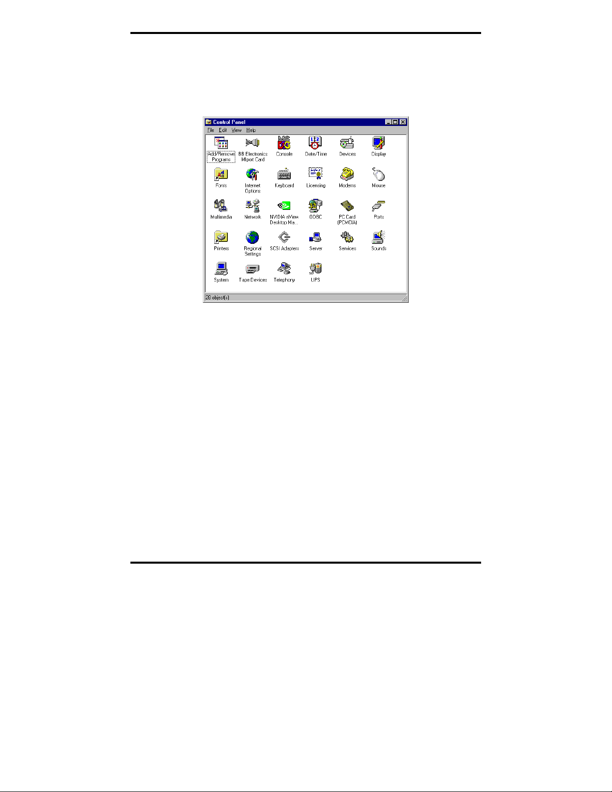
and several port parameters can be configured.
1. On the
2. On the
The dialog will display the current settings for Bits per second, Data
Ports (COM & LPT) list, double-click the name of the port to
be configured.
Port Properties dialog, click the Port Settings tab.
bits, Parity, Stop bits and Flow control. If necessary,
change these settings to the required values.
Figure 30. The Port Settings Dialog
3. Click Advanced…
40 Chapter 4 Manual Documentation Number 3PCIoUx-1008
Page 47

Setting Driver Options
The Advanced Port Settings dialog will appear. This screen allows
you to set the Receive and Transmit FIFO buffer thresholds, RTS
Control parameters, Hardware handshaking hysteresis level and the
COM port name.
Figure 31. The Advanced Settings for COM# dialog
Setting the FIFO Buffers
MIport cards use UARTs that contain 64-byte transmit and receive FIFO
(first in, first out) buffer registers. The transmit buffer holds the data to be
sent; the receive buffer holds the data received.
The
Transmit buffer: Low parameter in the Advanced Port Settings dialog
allows you to set the minimum value at which the UART will request more
data from the computer. As the MIport card is transmitting data, the number
of bytes left in the transmit buffer will decrease. When the buffer reaches the
value set, the UART will request more data from program memory. This is
intended to optimize the throughput of the data. Typically this parameter is
set at zero and usually does not have to be changed.
The
Receive buffer: Low parameter in the Advance Port Settings dialog
allows you to set the value at which the UART will request that the computer
read the data that has been received. As the MIport card is receiving data the
contents of the receive buffer increases, when it reaches the value set, the
Manual Documentation Number 3PCIoUx-1008 Chapter 4 41
Page 48

Setting Driver Options
UART will request that the computer transfer the contents of the buffer to
program memory. This is intended to optimize the throughput of the data.
The default value is 14. Usually this parameter does not have to be changed.
Setting the RTS Control Parameter
1. Set RTS Control to Normal for RS-232; set RTS Control to RS-
485 Mode for 2-wire or 4-wire RS-485 operation. Either setting can
be used for RS-422.
Typically the COM parameters set in this dialog box are overridden
by the software application.
Note: For proper operation the DIP switches on the PCI card must be
set for the same mode. Refer to Chapter 2 for more information on
configuring the DIP switches.
2. The Direction control delay (bit times) box allows you to set the
length of time the Transmit driver continues to be enabled after the
last bit of data in the transmit register has been sent. The purpose of
this setting is to maintain the transmission line in a know (idle) state
until the data has reached its destination. If the line is released too
soon it can pick up noise that could cause problems on the
communications system. This parameter is preset to a value of 10
bit times and typically will not have to be changed. For longer
transmission lines this value may have to be increased.
Setting the Hardware Handshaking Level
The Hardware handshaking Hysteresis level (characters) parameter
allows you to set how long the local UART will continue to accept data after
its receive buffer has reached the point at which it asks the computer to
transfer the data to program memory. When this point is reached the UART
de-asserts the RTS hardware handshake line (which is connected to the
remote UART’s CTS line), stopping the remote device from sending data
until its CTS line is re-asserted. This will occur when the local receive FIFO
buffer has been cleared. The default value for this parameter is 0. Typically
this value will not need to be changed.
Changing the COM Port Name/Number
1. To change the COM port number assigned to the port, click the
COM Port Name arrow and select the new COM Port Name from
the list.
42 Chapter 4 Manual Documentation Number 3PCIoUx-1008
Page 49
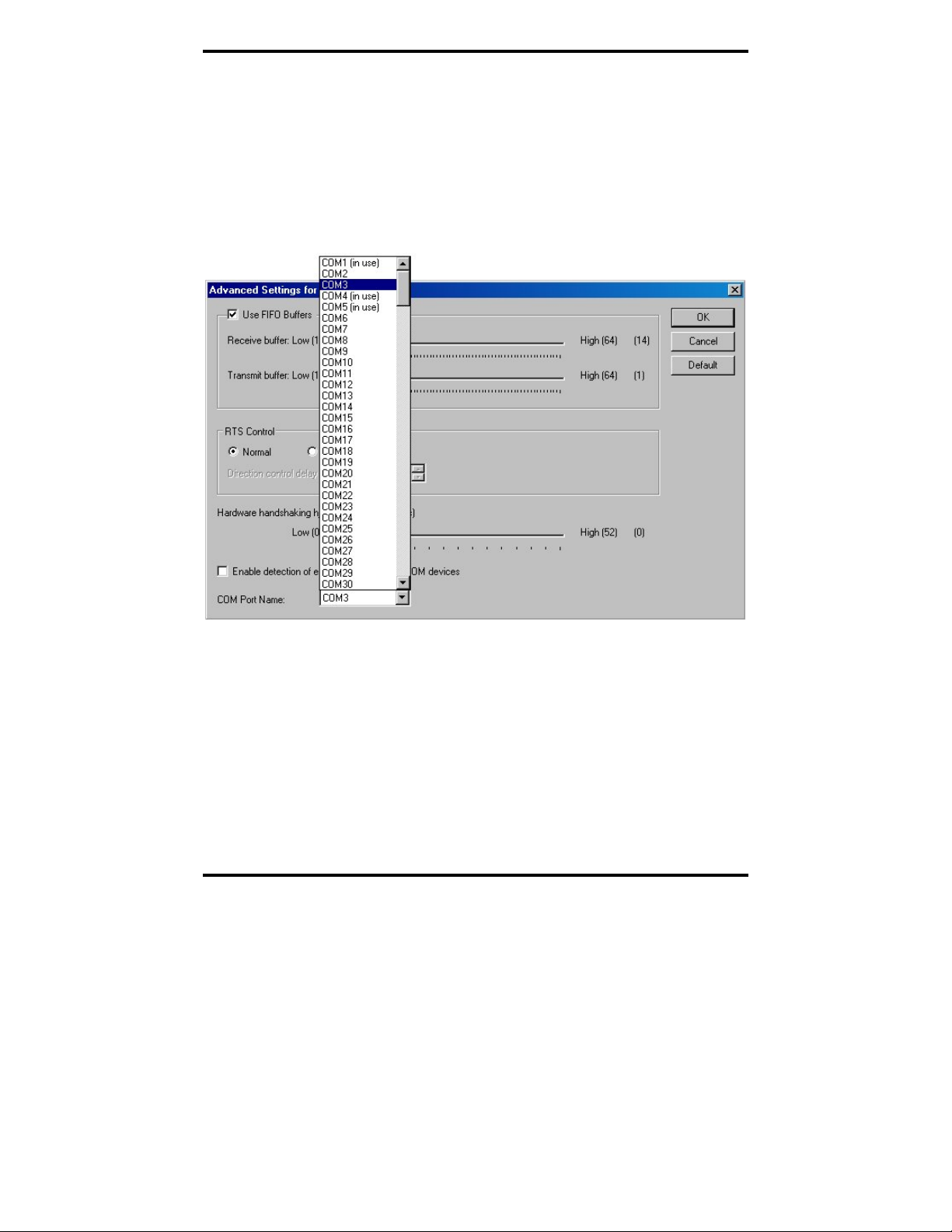
Setting Driver Options
Available names for COM numbers are shown. Select a new number
from those not “in use”. COM numbers from COM1 to COM256
may be available. COM numbers “in use” may be used by
motherboard ports, modems, virtual COM ports for network serial
server devices or FAX modems. Formerly installed USB to serial
adaptors, PCI cards or other hardware may have reserved a COM
number. The device may need to be added back to the system, then
the software removed. Advanced editing of the registry may
required to clean up the problem. Special permissions are required
with 2000 or XP.
Figure 32. Changing the COM Port Name/Number
2. After selecting a new COM name/number, Click OK, then click
OK again on the Settings page.
After returning to the
Device Manager screen, it should refresh
automatically. The name/number of the port in the Device Manager
list should now show the change.
Manual Documentation Number 3PCIoUx-1008 Chapter 4 43
Page 50

Installing Linux Driver Software
CChhaapptteerr 55:: IInnssttaalllliinngg LLiinnuuxx DDrriivveerr
Installing MIport Drivers in Linux
Note to the Editor(s): All commands and directories are case sensitive in
Linux. When updating this section, be very careful about then things are
uppercase or lowercase.
Installation of the Linux driver software for MIport cards is a three-step
process:
1. Preparing the Linux files
2. Compiling the driver
3. Installing the driver
Preparing the Linux Files
The following procedure assumes you have mounted your MIport driver CDROM under /mnt/cdrom
1. Open a terminal window and execute the following steps at the
command prompt.
SSooffttwwaarree
2. Change to a user directory on your system:
cd /home/username
3. Untar the driver files
tar zxpf /mnt/cdrom/Linux/Drivers/MIport-1.0.0.tar.gz
Compiling the Driver
Open a terminal window and execute the following steps at the command
prompt to ompile and install the driver:
1. Change to installation directory:
cd /home/username/bbelec/drivers/MIport
44 Chapter 5 Manual Documentation Number 3PCIoUx-1008
Page 51
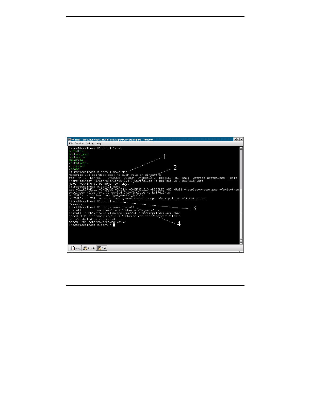
Installing Linux Driver Software
2. Remove any temporary files:
make clean
3. Make a dependency file:
make dep
4. Make the driver file:
make
Installing the Driver
1. If the user is not root, switch to the root user
su
2. Install the driver files as root
make install
Figure 33. Building the Driver in a Terminal Window
Manual Documentation Number 3PCIoUx-1008 Chapter 5 45
Page 52

Installing Linux Driver Software
3. Make the device nodes:
a.
b.
4. Modify the startup script to automatically start the driver:
cp /home/username/bbelec/drivers/MIport/rc.bb17d15x /etc/rc.d
WARNING: Do not overwrite /etc/rc.d/rc.serial if it already exists!
Note: These scripts will create the device nodes /dev/tty/M0/ and/dev/cum0
for each port, where the 0 is the number of the port.
If
/etc/rc.d/rc.serial already exists append the commands from:
/home/username/bbelec/drivers/MIport/rc.serial
to
/etc/rc.d/rc.serial
The commands in /home/username/bbelec/drivers/MIport/rc.serial are:
./bbmknod_sh if the system uses sh for its shell
./bbmknod_csh if the system uses a c-shell environments
#!/bin/sh
if [ -f /etc/rc.d/rc.bb17d15x ]; then
sh /etc/rc.d/rc.bb17d15x
fi
5. Restart the computer
/sbin/shutdown –r now
Note: Only the root user and members of the “uucp” group will have
access to the driver. Add users to the “uucp” group as needed.
46 Chapter 5 Manual Documentation Number 3PCIoUx-1008
Page 53

Installing Linux Driver Software
Checking the Driver Installation
Open a terminal window and execute the following steps at the command
prompt to check the driver installation:
1. If the user is not root, then switch to the root user:
su
2. Check that the driver is running:
/sbin/lsmod | grep bb17d15x
3. Switch from the root user back to the user
4. a. Copy rc.bb15d15x
cp /home/username/bbelec/drivers/MIport/rc.bb17d15x/etc/rc.d
b. Modify or create /etc/rc.serial to call /etc/rc.d/rc.bb.17d15x
WARNING: DO NOT OVERWRITE AN EXISTING
/etc/rc.serial
If /etc/rc.serial already exists
following commands to the end of the file:
if [ -f /etc/rc.d/rc.bb17d15x ]; then
sh /etc/rc.d/rc.bb17d15x
fi
If /etc/rc.serial does not exist
command:
cp /home/username/bbelec/drivers/MIport/rc.serial/etc/rc.d
c. Modify /etc/rc.d/rc.local to call /etc/rc.d/rc.serial
If the following commands are not in /etc/rc.d/rc.local , then
add them to the end of the file:
if [ -f /etc/rc.d/rc.serial ]; then
sh /etc/rc.d/rc.serial
fi
5. Switch from the root user back to the user with the command:
in /etc/rc.d then add the
, then copy it with the following
exit
Manual Documentation Number 3PCIoUx-1008 Chapter 5 47
Page 54

Installing Linux Driver Software
Using the Exar Serial GUI Example Application
The Exar Serial Test GUI is a program included on your MIport software CD
that can be used to check the operation of your MIport card. The following
procedure describes how to set up and run this application.
Preparing the Example Application Files
1. Open a terminal window and execute the following steps at the
command prompt.
2. Change to a user directory on your system:
cd /home/username
3. Untar the driver files
tar zxpf /mnt/cdrom/Linux/Programs/exser.tar.gz
4. See /home/username/GUI/INSTALL for instructions on compiling
and installing the application.
Running the Exar Serial Test GUI
5. To run the Exar Serial Test GUI:
a. Launch the application from a terminal window:
/home/username/GUI/exser/exser &
or
b. Edit the menu for your windows manager and add
/home/username/GUI/exser/exser as an application.
48 Chapter 5 Manual Documentation Number 3PCIoUx-1008
Page 55

Installing Linux Driver Software
Figure 34. The Blank Application Window
6. Click File, Open. The Open Device dialog will appear.
Figure 35. The Open device dialog box
7. Type the name of the device in the File name box. The name will be
ttyM0, ttyM1, etc. Click Open.
The screen will change from gray to white and the name of the file
will appear at the top of the screen.
Manual Documentation Number 3PCIoUx-1008 Chapter 5 49
Page 56

Installing Linux Driver Software
Figure 36. The Open Application Window
Configuring Port Settings
1. Click Serial, Port Settings. The Serial port parameters dialog will
appear. The dialog will display the current serial port settings. Enter
the parameters required for your application.
Note: Refer to Chapter 4 for detailed explanations of serial port
settings.
Figure 37. The Exar Serial Port Parameters dialog
50 Chapter 5 Manual Documentation Number 3PCIoUx-1008
Page 57

Removing Drivers, Ports and Cards
CChhaapptteerr 66:: RReemmoovviinngg DDrriivveerrss,, PPoorrttss aanndd
CCaarrddss
You may need to remove the card from your system or remove the current
driver before installing a driver upgrade. The following sections describe
removal procedures.
Removing MIport Cards from Win98/ME/2000/2003
Server/XP/Vista
Uninstalling the MIport Card
1. In the Device Manager, under Multi-port serial adapters, right-
click the card to be uninstalled. NOTE: The card must still be
physically installed in the computer, otherwise it will not show up in
the Device Manager.
2. In the pop-up menu that appears, click
3. On the
4. After a few seconds the dialog will disappear. In the
Confirm Device Removal dialog that appears, click OK.
Manager the listings for the card (under Multi-port serial adapters)
and all associated COM ports (under Ports (COM & LPT)) will be
gone.
Uninstall.
Device
5. Physically remove the MIport card from the computer.
Uninstalling the COM ports
1. In the Device Manager, under Ports (COM & LPT), right-click
the COM port to be uninstalled.
2. On the
3. After a few seconds the dialog will disappear. In the
This procedure will not affect other ports or the card itself. To
uninstall the card and all its ports use the preceding procedure.
Manual Documentation Number 3PCIoUx-1008 Chapter 6 51
Confirm Device Removal dialog that appears, click OK.
Device
Manager the listings for the port (under Ports (COM & LPT)) will
be gone.
Page 58
Removing Drivers, Ports and Cards
Removing INF and PNF Driver Files
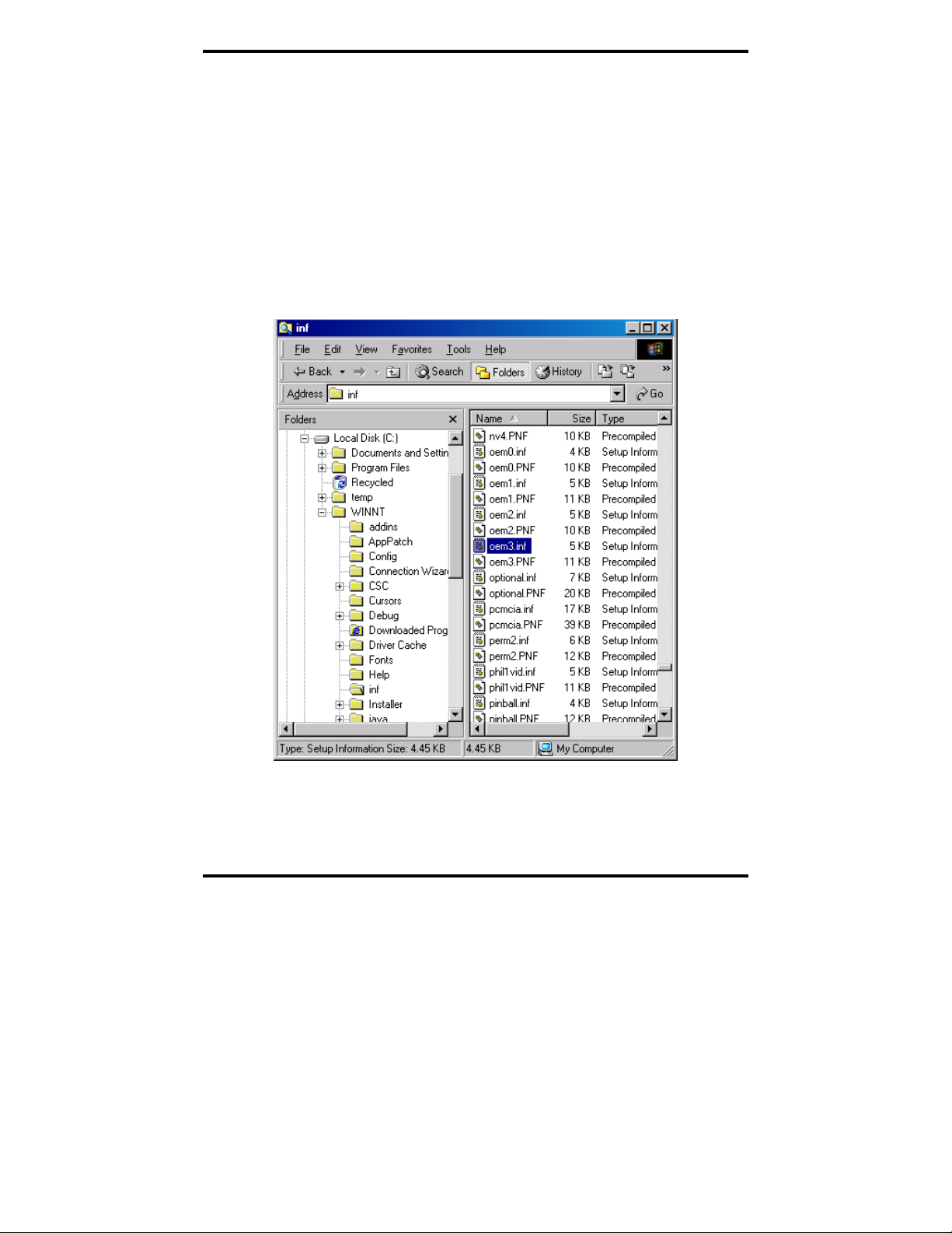
1. Open Windows Explorer as follows: From the Windows Desktop,
click
Programs → Accessories → Windows Explorer
2. Under the Windows directory expand the inf sub-directory and find
the oemX.inf and oemX.PNF files (where X represents the number
of the file).
The operating system names these files during the installation
process. To locate the correct INF files, search for files in
C:\Windows\Inf and its subdirectories for a file named *.INF that
contains the text “Disk #6404”. There will be two files, unless the
installation failed, then there might only be one file. Then, the
customer can double-check that it is in fact a B&B Electronics file.
Figure 38. Finding the INF files in Windows Explorer
To find these files you may need to set your Views (under My
Computer) to show all files and folders if the INF directory and .inf
files are not visible.
52 Chapter 6 Manual Documentation Number 3PCIoUx-1008
Page 59
Removing Drivers, Ports and Cards
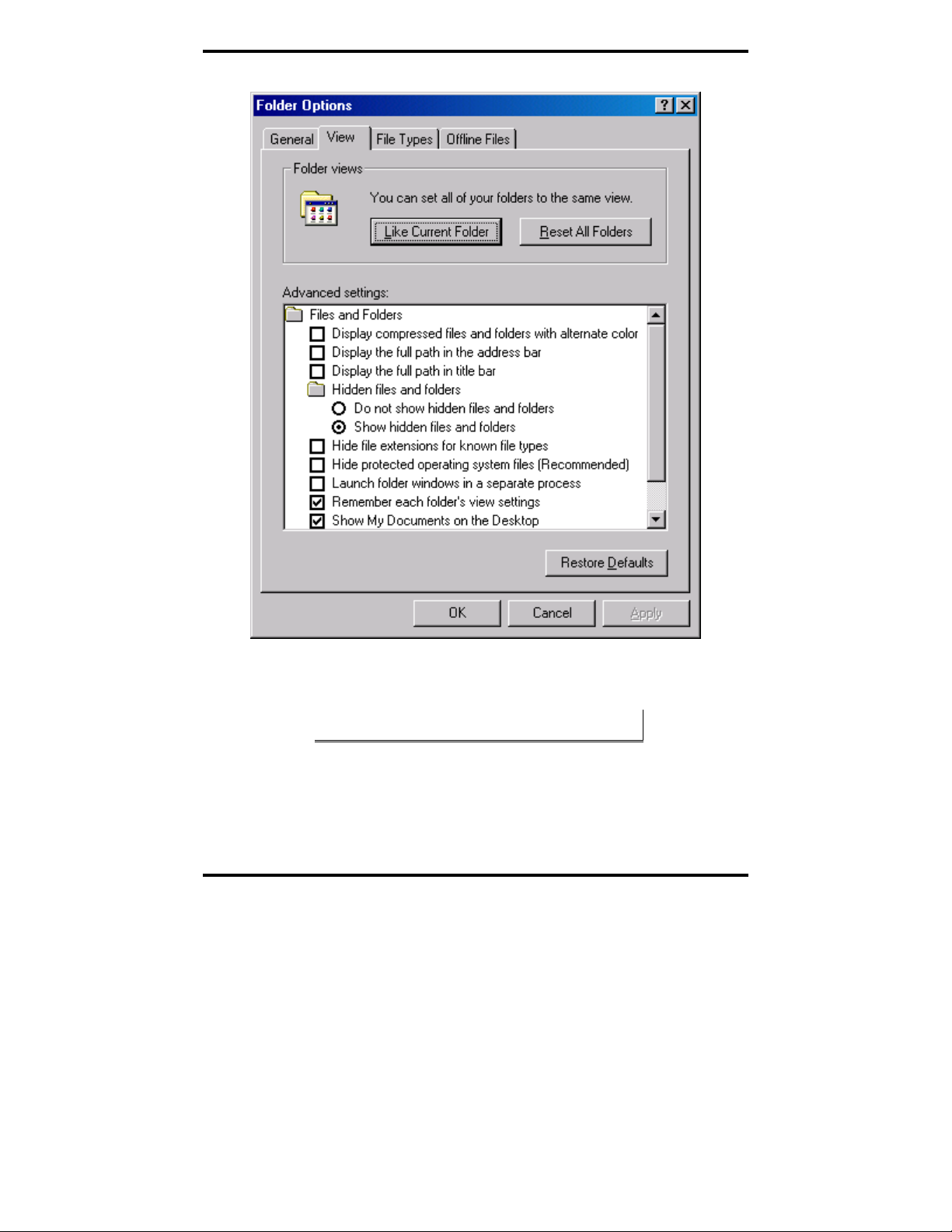
Figure 39. Setting the Folder Options to Display Hidden Files
3. Delete the oemx.inf and oemx.pnf files found in Step 2..
CAUTION! Be careful to delete only the files associated with the PCI
card you are trying to uninstall.
Manual Documentation Number 3PCIoUx-1008 Chapter 6 53
Page 60

Removing Drivers, Ports and Cards
Removing MIport Cards from Windows NT
Uninstalling the MIport Card
1. The Driver must be uninstalled.
Uninstalling the Driver
1. Using Windows NT Explorer locate the uninstall.exe file in the
B&B installation directory. (The default installation directory is
C:\Program Files\B&B Electronics\MIport)
Figure 40. Uninstall.exe in the B&B Program Files
2. Double-click the Uninstall.exe file name. The Select Uninstall
Method
3. Select
dialog will appear.
Automatic and click Next. The Perform Uninstall dialog
will appear.
4. Click
5. Return to
Finish.
Windows NT Explorer and refresh the window (Click
View, then click Refresh). The MIport subdirectory under
C:\Program Files\B&B Electronics should no longer be there.
54 Chapter 6 Manual Documentation Number 3PCIoUx-1008
Page 61

RS-232 Connections/Operation
CChhaapptteerr 77:: RRSS--223322
CCoonnnneeccttiioonnss//OOppeerraattiioonn
RS-232 Mode
In RS-232 Mode MIport serial ports function as buffered standard PC serial
ports and operate as DTEs (Data Terminal Equipment). RS-232 interfaces are
commonly used for communications with modems, serial printers, and
computer-controlled devices such as security equipment, bar code scanners
and point-of-sale devices.
RS-232 Signal Designations and DB-9 Pinout
RS-232 Mode supports eight single-ended signal lines and signal ground. The
DB-9 male connector is configured as a standard RS-232 (DTE) serial port.
The table below shows the signal names and pin numbers.
RS-232 Signal
Name
DCD Data Carrier Detect Input 1
RD Receive Data Input 2
TD Transmit Data Output 3
DTR Data Terminal Ready Output 4
GND Signal Ground ------ 5
DSR Data Set Ready Input 6
RTS Request to Send Output 7
CTS Clear to Send Input 8
RI Ring Indicator Input 9
RS-232 Signal
Description
Direction
(DTE)
DB-9M
Pin
Figure 41. RS-232 Signal Designations and DB-9 Pinout
Note: Refer to Appendix B for additional cable configurations and
pinouts
Manual Documentation Number 3PCIoUx-1008 Chapter 7 55
Page 62

RS-232 Connections/Operation
RS-232 Signal Designations
The primary RS-232 signals are TD (transmit) and RD (receive). Together
with GND (ground), they often are referred to as a “3-wire” interface.
The
RTS (Request to Send) and CTS (Clear to Send) signals are handshaking
lines used to indicate to the other device that data can be sent or received.
These lines may be enabled or disabled on a byte-by-byte basis and are used
to prevent buffer overrun or the loss of data.
Two secondary handshaking signals are
DSR (Data Set Ready). They are usually enabled when the device is powered
up and the port is open. They may be used for flow control by some devices
instead of RTS and CTS.
DCD (Data Carrier Detect) is used by a modem to indicate Carrier to the
computer so data can be sent/received.
RI (Ring Indicator) is output by a modem to indicate that the phone or FAX
line has a incoming call, so it can be handled.
DTE and DCE
There are two types of RS-232 ports:
DTE (Data Terminal Equipment) which is typically a computer
•
DCE (Data Communications Equipment) which is typically a modem.
•
Data Terminal Equipment (DTE)
When a DTE is connected to a DCE they are linked directly together using a
modem cable wired pin to pin so that the inputs match the outputs of the
other.
Data Communications Equipment (DCE)
DTR (Data Terminal Ready) and
When two pieces of equipment of the same type are interconnected (a DTE
connected to a DTE, or a DCE to a DCE), a crossover (often called a null
modem) cable is needed to route the outputs of one to the inputs of the other.
This type of cable is needed to interconnect two computers with RS-232.
Note: Refer to Appendix B for straight-through and null modem cable
diagrams and pinouts.
56 Chapter 7 Manual Documentation Number 3PCIoUx-1008
Page 63

RS-232 Connections/Operation
RS-232 Signal Levels
RS-232 signal lines are referenced to ground, and each signal can alternate
above and below ground. The RS-232 standard specifies output voltages
must be no less than +5 volts and no greater than +25 volts to represent a
Space on a transmit line (or an asserted handshake line). Output voltages
must be between –5 volts and –25 volts to represent a Mark on a transmit line
(or an de-asserted handshake line).
The standard specifies that RS-232 inputs accept voltage levels between –3
volts and –25 volts for a Mark (asserted handshake) and between +3 volts to
+25 volts for a Space (de-asserted handshake). Typically RS-232 voltages
will be between +3V to +11V and –3V to –11V.
Handshaking
To control the flow of data between two devices, some software uses
hardware handshaking. RS-232 devices which require hardware handshaking
require connection of RTS/CTS and/or DTR/DSR lines in order to operate
properly.
Programs for RS-232 may chose to use only the RS-232 TD and RD data
lines and ignore hardware handshaking inputs (set up as None in the port
configuration). In some cases the software may require connections to verify
that a cable is connected and the devices are ready for access (typically
DTR/DSR is used).
Some devices may use software handshaking in which data characters (e.g.
Xon/Xoff ) are sent to start and stop the incoming or outgoing data. These
unprintable characters have the decimal value (17) and (19), and can often be
generated in a terminal program with CTL+Q or CTL+S.
RTS Control In RS-232 Mode
In RS-232 mode, MIport cards support software and hardware handshaking.
Handshake lines can be controlled from the communications software used
with your application. When operating a MIport card port in RS-232 mode,
set the
RTS Control driver setting to Normal. This ensures that the RTS line
will be free to be controlled by your software. If your communications
software uses software handshaking, hardware handshake lines will not be
required.
Manual Documentation Number 3PCIoUx-1008 Chapter 7 57
Page 64

RS-232 Connections/Operation
Figure 42. RTS Control – Select Normal for RS-232 Operation
58 Chapter 7 Manual Documentation Number 3PCIoUx-1008
Page 65
RS-422/ 485 Connections/Operation
RS-422/485 Mode
In RS-422/RS-485 mode MIport serial ports provide two sets of differential
signal pairs and signal ground for each port. The RS-422 and RS-485
standards use balanced differential drivers and receivers for each signal. This
facilitates greater communication distances than unbalanced systems such as
RS-232.
RS-422 operation is suitable for interconnecting a computer and one device
for full duplex (point-to-point) bi-directional communication, or a computer
and several devices for unidirectional (point-to-multipoint) communication.
RS-422 interfaces are commonly used for video editing/control, camera
control, electronic signage, television studio/satellite dish control,
performance lighting and audio equipment control.
RS-485 operates with the same signals and signal levels as RS-422 but differs
in that it allows multiple devices to share the same communication link using
half duplex (2-wire) or full duplex (4-wire) connections. RS-485 interfaces
are commonly used in manufacturing and industrial/commercial control
applications such as programmable logic controllers, telemetry, and process
control.
CChhaapptteerr 88:: RRSS--442222//448855
CCoonnnneeccttiioonnss//OOppeerraattiioonn
RS-422/485 Signal Designations and DB-9 Pinout
Name Description Direction DB-9 M Pin
RD(A) −
TD(B) + Transmit Data B Output 2
TD(A) −
GND Signal Ground ------ 5
RD(B) + Receive Data B Input 9
Figure 43. RS-422/485 Signal Designations and DB-9 Pinout
Note: Refer to Appendix B for additional cable configurations and
pinouts
Manual Documentation Number 3PCIoUx-1008 Chapter 8 59
Receive Data A Input 1
Transmit Data A Output 3
Page 66

RS-422/485 Connections/Operation
RS-422/485 Signal Designations
Typically RS-422 and RS-485 interfaces use five lines including two signal
pairs and ground. One signal pair is the transmit pair, labeled
TD(B)+. The other signal pair is the receive pair, labeled RD(A)- and RD(B)+.
Signal ground is labeled
GND.
TD(A)- and
RS-422/485 Differential Signals
In RS-422 and RS-485 interfaces signals are sent on differential pairs. In the idle, or
Mark, state, the TD(A)- line will be 0V with respect to (wrt) ground and the TD(B)+
line will be about 4.4V wrt ground. Sensing differentially across the two lines, the
voltage will be –4.4V (representing a Mark state). When the transmitter changes to the
Space state TD(A)- goes to +4.4V and TD(B)+ goes to 0V. In that state the differential
voltage will be +4.4V
Figure 44. Differential transmitter/receiver
The receiver input is a differential circuit which senses the difference in
voltage across the transmission line as described above. In addition, any
common mode noise picked up equally on both wires of the twisted pair is
cancelled. Receiver sensitivity is rated at 200mV. A separate signal
ground/common connection provides a common mode reference for the
transmitter and receiver (and is often used to ground a shield in the cable).
These factors provide reliable communications at much greater distances than
RS-232.
60 Chapter 8 Manual Documentation Number 3PCIoUx-1008
Page 67

RS-422/ 485 Connections/Operation
RS-422 Operation
In RS-422 mode, the transmitter is enabled (TX ENABLE) all the time, and
the receiver is enabled (RX ENABLE) all the time. Typical point-to-point
connections use a transmitter and receiver at each end with two wire pairs
connecting them. The transmit lines of the device at one end of the link are
connected to the matching receive lines of the device at the other end. The
second device transmit lines are connected to the receive lines of the first.
Another common connection mode—point to multipoints—connects the
transmit pair from the master device transmitter to the receive lines of many
listening slave devices. In this scenario the communications is one-way.
None of the listening devices have transmitters connected to reply to the
master.
RS-422 Limitations
The limitation of RS-422 operation is that only one transmitter can be
connected to a wire pair because the transmitter is active all the time. Even
when the transmitter is not sending data it will assume the idle, or Mark, state
in which TD(A)- is at 0V with respect to ground and TD(B) line is at about
4.4V with respect to ground. If another transmitter output is connected to the
same wire pair, and attempts to begin sending data by setting the line pair to
Space state, the first transmitter will hold the opposite state and neither can
communicate. To overcome this limitation, RS-485 mode was developed, in
which transmitters connected to the line are put into a high-impedance (tristate) state when not transmitting.
RS-485 Operation
RS-485 solves some of the limitations of RS-422, allowing multidrop
communications using 2-wire and 4-wire connections from multiple
transmitters and receivers.
To accomplish multidrop operation the transmit driver must be enabled only
during transmit (by asserting the enable input (TX SD) of the transmitter) and
tri-stated to a high impedance after the data has been sent. In the 2-wire (half
duplex) mode, the receiver is enabled when not transmitting, and disabled
(RX
device receive its own transmissions).
Manual Documentation Number 3PCIoUx-1008 Chapter 8 61
) during transmit (called ‘echo off’ because it avoids having the
Page 68

RS-422/485 Connections/Operation
Figure 45. An RS-485 Two-Wire Multidrop Connection
Send Data Control
MIport cards provide Send Data Control (SDC) for the RS-485 driver and
receiver. This is hardware controlled based on the contents of the UART
output buffer. When data is present, the driver is enabled; when the output
buffer becomes empty, it is disabled. This automatically handles whatever
baud rate is used.
The RS-485 transmitter and receiver have separate settings for 2-wire modes
(TX SD, RX SD) or 4-wire (TX SD, RX ENABLE).
Figure 46. Setting RTS Control for RS-485
62 Chapter 8 Manual Documentation Number 3PCIoUx-1008
Page 69

RS-422/ 485 Connections/Operation
The RS-485 mode is set by configuring the DIP switch setting on the MIport
card and by selecting RS-485 Mode under RTS Control in the Advanced
COM port settings dialog box.
Note: For more information on COM port settings refer to Chapter 2
and Chapter 5
RS-485 Termination Resistors
In some applications termination resistors must be connected across the
communications line to ensure reliable communications. Termination
resistors absorb signal reflections that can occur when a data signal reaches
the end of a transmission line and encounters an impedance higher than that
of the transmission line itself. Typically termination resistors are not required
for communications links that operate at less that 19.2 kbps. At higher bit
rates a termination resistor of 120 ohms may be required. Termination
resistors should be connected across the communications line at the extreme
opposite ends of the network.
Through hole pads are provided on MIport cards to install termination
resistors. When adding termination resistors the value of biasing resistors
must be appropriately sized as well.
RS-485 Network Biasing
Unlike RS-422, where the transmitter holds the TD(B)+ line high and the
TD(A)- line low (in the idle, or Mark state) when not transmitting data, in a
RS-485 network, the transmitter tri-states to a high impedance state when not
sending data.
It is important to maintain the Mark state for all RS-485 receivers when no
data is being sent. Maintaining the line in the Mark state minimizes noise
(that would otherwise be picked up by a high impedance line). It also
provides the starting point so that when a transmitter begins to send data the
leading edge of the start bit can transition from the Mark to Space state.
To maintain the Mark state biasing is required. Biasing is the technique of
placing pull up (to positive voltage) and pull down (to ground) resistors on
the line so that all RD(A)- receiver inputs remain at least 200 mV more
negative than RD(B)+ inputs (Mark state). This ensures the inputs will
remain above the receiver threshold of 200mV for all devices on that section
of the network. If the biasing is not maintained, the first data bit of a signal
may not be detected, and one or more devices may not respond to commands,
or may operate intermittently.
Manual Documentation Number 3PCIoUx-1008 Chapter 8 63
Page 70

RS-422/485 Connections/Operation
Figure 47. RS-485 Biasing Resistors
MIport RS-485 receivers come pre-biased from the factory with a 4.7 kΩ
pull-up resistor on the RD(B)+ line and a 4.7 kΩ pull-down resistor on the
RD(A)- line. These values are usually adequate for networks that do not
implement termination resistors and have 31 or fewer nodes. When
termination is used, biasing must be increased (resistors decreased),
calculated according to the termination value and number of nodes.
Through hole pads are provided on MIport cards for adding termination
resistors and bias resistors. The photograph below shows the layout of
through hole pads for installing termination and bias resistors. On all MIport
cards the top set of holes is for the termination resistor. The middle and
bottom sets of holes are for bias resistors. (Note the factory installed 4.7k
resistors in the photograph.) Since bias resistors are always the same value
(e.g R pullup = R pulldown = 4.7k) there is no need to identify which set of
holes is for pull up and which is for pull down.
Figure 48. Termination and Bias Resistor Placement
Note: For more information on termination, biasing and how to
calculate resistor values download the RS-422/485 Application Note
from www.bb-elec.com
64 Chapter 8 Manual Documentation Number 3PCIoUx-1008
Page 71

RS-422/ 485 Connections/Operation
2-Wire RS-485 Connections
The following diagram shows how to wire the DB-9 connector that will plug
into your MIport card for 2-wire RS-485 operation.
Figure 49. 2-Wire RS-485 Connections
2-Wire RS-485 Mode:
Your cables must bridge pins #1 & #3 and pins #2 & #9 in order to receive
and transmit. Connect from Pin #2 to Data B(+) of your devices and from pin
#3 to Data A(-) of your devices. Make sure your DIP switches are set, and
that the driver Setting for RTS Control is RS-485 Mode in the Device
Manager, Port Settings, Advanced.
Note that the EIA RS-422 Specification labels data lines with an "A" and "B"
designator. Some RS-422 or RS-485 equipment uses a "−" and "+"
designator. In most cases, the "A" line is the equivalent of the "−" line and
the "B" line is the equivalent of the "+" line. Some device manufacturers may
not follow the standard designation for RS-422 or RS-485, using the A
connection for “+” and the B for “-“. In such cases, reversing the line pair
permits operation.
4-Wire RS-422 and RS-485 Connections
RS-422 Point to Point Connection
For RS-422 point to point communications connect the MIport card and to
one RS-422 device only.
1. Connect the TD(B) pin #2 on the computer to RD(B) on the device.
2. Connect the TD(A) pin #3 on the computer to RD(A) on the device.
Manual Documentation Number 3PCIoUx-1008 Chapter 8 65
Page 72

RS-422/485 Connections/Operation
3. Connect the RD(B) pin #9 on the computer to TD(B) on the device.
4. Connect the RD(A) pin #1 on the computer to TD(A) on the device.
5. Connect the Signal Ground pin #5 to Signal Ground on the device.
RS-422 Point to Multipoints Connection
In a multi-slave RS-422 connection, TD(B) and TD(A) connect to RD(B) and
RD(A) on all the slaves. If the slaves have Transmit connections, only one
device can be connected back to the master.
Figure 50. RS-422 Master to RS-422 Receive Only Devices
4-Wire RS-485 Connection
In a 4-wire RS-485 system, each receive line connects to the same receive
terminal on all slaves, and each transmit line connects to the same transmit
terminal on all slaves. The master to the first slave is connected as above.
66 Chapter 8 Manual Documentation Number 3PCIoUx-1008
Page 73
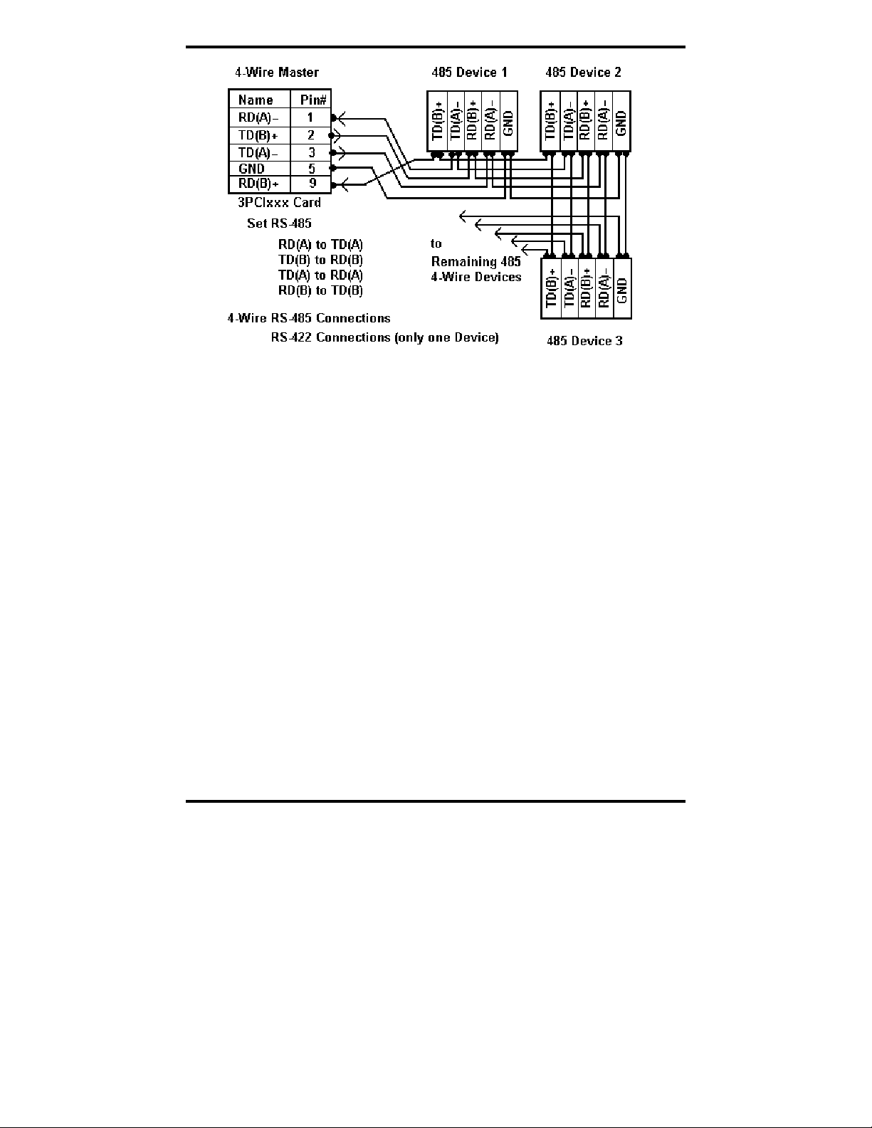
RS-422/ 485 Connections/Operation
Figure 51. 4-Wire RS-422 or RS-485 Connections
Manual Documentation Number 3PCIoUx-1008 Chapter 8 67
Page 74

Troubleshooting MIport Cards
CChhaapptteerr 99:: TTrroouubblleesshhoooottiinngg MMIIppoorrtt
Your MIport card should be fully functional when you receive it from the
factory. Operational problems encountered on first use will typically be the
result of incorrect connections or operation. The following procedure will
assist you in locating the source of you problems.
Starting Up
If you have any trouble starting your system after installing the card, the card
may not be properly seated in the slot. Power down the computer, remove
and re-insert it, or try a different slot. Ensure your system is set for PnP OS.
(Windows NT and Linux should be set to non-PnP.)
Checking Connections
RS-232/422/485 Operation
1. Ensure that you have set up your card for the correct mode of
operation (RS-232, RS-422, RS-485 2-wire or 4-wire) using the DIP
switches on the card and Advanced Port Settings.
Note: For more information on DIP switches refer to Chapter 2. For
more information on Driver Settings refer to Chapter 5.
CCaarrddss
2. Ensure your communications parameters (baud rate, parity, stop
bits) are set correctly at both ends of your link.
RS-232 Operation
1. MIport cards are DTE devices. If you are connected to a DCE
device use a straight through cable. If you are connected to another
DTE device, use a crossover, or null cable.
2. If hardware handshaking is required, ensure you have the right
cables and that both ends of your link are configured the same for
handshaking.
68 Chapter 9 Manual Documentation Number 3PCIoUx-1008
Page 75
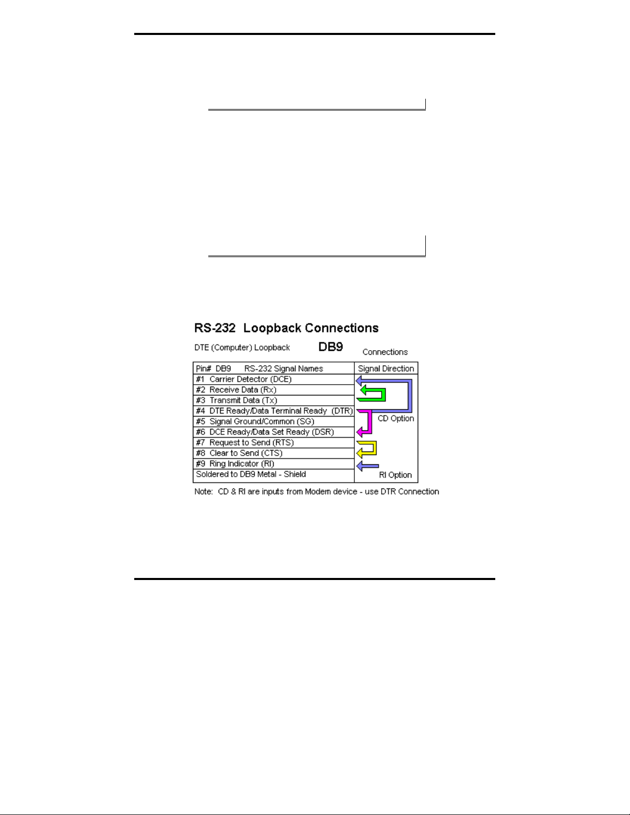
Troubleshooting MIport Cards
RS-422/485 Operation
1. Check your pinouts. In RS-422 or RS-485 mode the "A" lines
should match your "A" or "−" lines. "B" lines should match your
"B" or "+" lines.
Note: RS-422/485 pinouts are non-standard.
2. Make sure you have RTS Control set to the correct mode: Normal
for RS-232, RS-485 Mode for RS-485. RS-422 mode works in
either setting if the mode jumpers are set correctly.
Checking the MIport Card
Using ComTest and a loopback connection, you can check the operation of
your MIport card separate from the rest of your communications system.
Note: Refer to Appendix C for information on how to install and use
ComTest
1. A loopback connection for RS-232 connects the Transmit output to
the Receive input (pins #2 & #3 on the DB-9 connector). Use
connections below to check all.
Figure 52. RS-232 Loopback w/Handshaking Connections
2. For RS-422 or 4-wire RS-485, connect the TD(A) to RD(A) and the
TD(B) to RD(B). Then use the ComTest program to send
characters, and observe the characters being received.
Manual Documentation Number 3PCIoUx-1008 Chapter 9 69
Page 76

Troubleshooting MIport Cards
Figure 53. RS-232 Loopback Connector
3. To check 2-wire RS-485 RS-422 or 4-wire RS-485 Loopback
Connections, you must either enable the receiver by moving the
receive jumper to RX ENABLE mode, or use one port to transmit to
another 2-wire RS-485 port or converter by cross connecting and
loading ComTest twice, one copy for each port.
Characters typed in one copy of ComTest will appear in the receive
window of the other. Note that software must ignore the RS-232
handshaking lines in RS-422/RS485 mode, the input lines (CTS,
DSR, DCD, RI) are not pulled high.
4. Some manufacturers label their data connections for A and B
reverse of the standard for RS-422 or RS-485, so that the A line is
(+) and B line is inverted (-) following the IC standard. In such a
case, just swap the wires and try it. No damage occurs in the RS485 mode, just no devices will respond. The EIA standard for signal
labels defines the B line as positive relative to A during the
“MARK” state.
5. Try another software package for troubleshooting. Some
applications try to bypass the Windows drivers and access the
hardware directly.
6. Check the B&B website for available FAQs or troubleshooting
hints.
7. Contact B&B Electronics Technical Support for troubleshooting
assistance.
70 Chapter 9 Manual Documentation Number 3PCIoUx-1008
Page 77

Troubleshooting MIport Cards
Support
USA Office
Technicians are available at (815) 433-5100 to answer your questions from 8
AM - 5 PM weekdays (Central Time).
Email: support@bb-elec.com
European Office
Technicians are available at +353 91 792444 to answer your questions from
8:30 AM – 5 PM weekdays (GMT).
Email: support@bb-europe.com
Manual Documentation Number 3PCIoUx-1008 Chapter 9 71
Page 78

Page 79
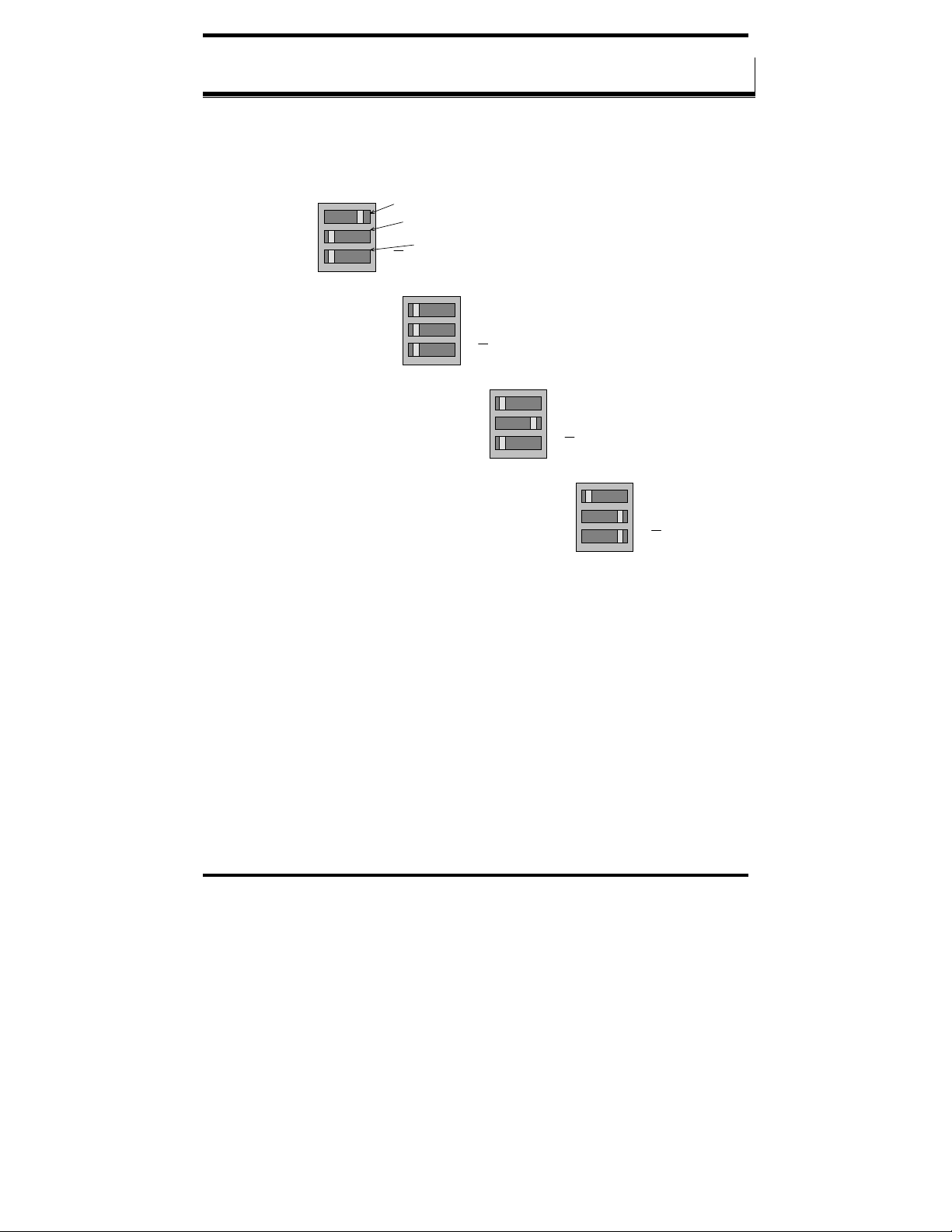
DIP Switch / Mode Settings
AAppppeennddiixx AA:: DDIIPP SSwwiittcchh//MMooddee SSeettttiinnggss
Setting the DIP Switches on RS-232/422/485 Ports
Set the DIP switches to configure the desired operating mode as follows:
422/485
TX On
RX On
RS-232 Mode
Switch 1
232
Switch 2
TX SD
RX SD
422/485
TX On
RX On
RS-422 Mode
Switch 3
232
TX SD
RX SD
422/485
TX On
RX On
4-wire RS-485 Mode
232
TX SD
RX SD
422/485
TX On
RX On
232
TX SD
RX SD
2-wire RS-485 Mode
Figure 54. RS-232/422/485 DIP Switch Settings.
DIP Switch 1 (RS-232/422/485 ports)
The top DIP switch (1) configures the port for RS-232 or RS-422/485
operation. This switch is the only one that is required to be set for RS-232
operation. The positions of switches 2 and 3 do not matter when switch 1 is
set for RS-232 operation.
DIP Switch 2 (RS-232/422/485 ports)
The middle DIP switch (2) configures the port for RS-485 or RS-422
operation. For RS-422 operation (which uses two wire pairs and sends pointto-point or point-to-multipoints) the transmitter can be enabled all the time.
Placing the middle DIP switch in the TX ON position accomplishes this.
Manual Documentation Number 3PCIoUx-1008 Appendix A A -1
Page 80

DIP Switch / Mode Settings
For RS-485 operation the middle DIP switch is placed in the TX SD position.
In this position the transmitter is only enabled when data is being sent. The
transmitter is tri-stated when not sending data, allowing other transmitters on
the communications line to transmit without interference.
DIP Switch 3 (RS-232/422/485 ports)
The bottom DIP switch (3) configures the port for half-duplex (two-wire)
RS-485 operation or full-duplex (four wire) RS-422/RS-485 operation.
Placing the bottom DIP switch in the RX ON position configures the port for
four wire operation. In this mode the receiver is continuously enabled,
allowing it to receive all data on the communications line. Since the
transmitter sends data on the other wire pair the port does not receive its own
transmissions.
Placing the bottom DIP switch in the RX
position configures the port for
two wire operation. In this mode the transmitter and receiver are connected to
the same wire pair. The receiver is disabled when its transmitter is sending,
preventing the port from receiving its own data.
Setting the DIP Switches on RS-422/485 Only Ports
The 3PCIOU4 MIport card provides a combination of RS-232/422/485 and
RS-422/485 only ports. Ports that do not include RS-232 operation use
double DIP switches rather than triple DIP switches. These DIP switches
operate the same as the two bottom DIP switches in the RS232/422/485 ports
TX On
RX On
RS-422 Mode
Figure 55. RS-422/485 only DIP Switch Settings
Switch 1
TX SD
Switch 2
RX SD
TX On
RX On
4-wire RS-485 Mode
TX SD
RX SD
TX On
RX On
2-wire RS-485 Mode
TX SD
RX SD
A-2 Appendix A Manual Documentation Number 3PCIoUx-1008
Page 81

DIP Switch / Mode Settings
DIP Switch 1 (RS-422/485 only)
The top DIP switch (1) configures the port for RS-485 or RS-422 operation.
For RS-422 operation (which uses two wire pairs and sends point-to-point or
point-to-multipoints) the transmitter can be enabled all the time. Placing the
middle DIP switch in the TX ON position accomplishes this.
For RS-485 operation the middle DIP switch is placed in the TX SD position.
In this position the transmitter is only enabled when data is being sent. The
transmitter is tri-stated when not sending data, allowing other transmitters on
the communications line to transmit without interference.
DIP Switch 2 (RS-422/485 only)
The bottom DIP switch (2) configures the port for half-duplex (two-wire)
RS-485 operation or full-duplex (four wire) RS-422/RS-485 operation.
Placing the bottom DIP switch in the RX ON position configures the port for
four wire operation. In this mode the port’s receiver is continuously enabled,
allowing it to receive all data on the communications line. Since the port’s
transmitter sends data on the other wire pair the port does not receive its own
transmissions.
Placing the bottom DIP switch in the RX
position configures the port for
two wire operation. In this mode the port’s transmitter and receiver are
connected to the same wire pair. The receiver is disabled when its transmitter
is sending, preventing the port from receiving its own data.
Manual Documentation Number 3PCIoUx-1008 Appendix A A -1
Page 82

Page 83

Connector Pinouts
AAppppeennddiixx BB:: CCOONNNNEECCTTOORR PPIINNOOUUTTSS
RS-232 Pinouts
Name Description Direction
DCD Data Carrier Detect Input 1
RD Receive Data Input 2
TD Transmit Data Output 3
DTR Data Terminal Ready Output 4
GND Signal Ground ------ 5
DSR Data Set Ready Input 6
RTS Request to Send Output 7
CTS Clear to Send Input 8
RI Ring Indicator Input 9
Figure 56. RS-232 Signal Designations and DB-9 Pinout
Signal Name DB-9 Pin
DCD 1 8
DTR 4 20
GND 5 7
DSR 6 6
RTS 7 4
CTS 8 5
Chassis GND Shield (DB-
DB-9M
(DTE)
DB-25 Pin
(DTE)
RD 2 3
TD 3 2
RI 9 22
9 Shell)
(DTE)
1
Pin
Figure 57. RS-232 DB-9 to DB-25 Conversion Cable Pinout
Manual Documentation Number 3PCIoUx-1008 Appendix B B -1
Page 84

Connector Pinouts
RS-422/485 Pinouts
Name Description Direction DB-9M
RD(A) −
TD(B) + Transmit Data B Output 2
TD(A) −
GND Signal Ground ------ 5
RD(B) + Receive Data B Input 9
Figure 58. RS-422/485 Signal Designations and DB-9 Pinout
With 2-wire RS-485 mode operation, your connection cable must jumper
TD(A) to RD(A) and TD(B) to RD(B). Connect from TD(A) and TD(B) to
the Data A(−) and Data B(+) wires of your RS-485 network.
Note: Refer to Chapter 2 for example connections.
Note that the EIA RS-422 Specification labels data lines with an "A" and "B"
designator. Some RS-422 equipment uses a "−" and "+" designator. In almost
all cases, the "A" line is the equivalent of the "−" line and the "B" line is the
equivalent of the "+" line.
Receive Data A Input 1
Transmit Data A Output 3
Pin
Note: For more information on RS-422 communications refer to the
B&B Electronics RS-422/485 Application Note at www.bb-elec.com
Figure 59. 2-Wire RS-485 Wiring Diagram
B-2 Appendix B Manual Documentation Number 3PCIoUx-1008
Page 85

Connector Pinouts
Figure 60. 2-Wire RS-485 Wiring
Manual Documentation Number 3PCIoUx-1008 Appendix B B -1
Page 86

Page 87

Troubleshooting with ComTest
AAppppeennddiixx CC:: TTrroouubblleesshhoooottiinngg WWiitthh
CCoommTTeesstt
ComTest is a simple 32-bit Windows (Windows 98, 2000, 2003 Server, ME, XP, NT
4.0 and Vista) COM port test program included on the MIport CD. (It can also be
downloaded from the B&B Electronics website at:
allows multiple ports at any address and IRQ, to be opened at any given time.
ComTest Features
• A Windows Terminal Program for Simple Checks of Serial Ports. Works
with USB Serial Converters & ISA or PCI Serial Cards
• Serial Port Access under Windows 98/2000/2003 Server/XP/Vista –
COM1-COM8 or above.
• Dual Windows show typed transmit characters in a separate window
from received characters.
• Transmit & Receive Activity Indicators
• Unprintable Characters Shown in Hex – 2 Digits Within Left & Right
Angle Brackets.
• Visual Indication of Handshaking Lines – DTR DSR DCD and RTS
CTS. (Red = Hi)
• Option for Setting DTR or RTS lines high or low.
• Option for Repeat Mode – last character or Function Character Sequence
is repeated until set off.
• Configuration Settings:
o Baud Rates 150, 300, 600, 1200, 2400, 9600, 19.2, 28.4, 57.6,
115.2K (9600 default and recommended)
o Parity: None, Odd, Even, Mark, Space (None default)
o Data Bits: 5, 6, 7, 8 (8 default)
o Stop Bits: 1, 1.5, 2 (1 default)
www.bb-elec.com. The program
Manual Documentation Number 3PCIoUx-1008 Appendix C C-1
Page 88

Troubleshooting with ComTest
Installing ComTest
1. From Windows Explorer, under Windows, Programs, COMTest,
find the setup.exe file on the MIport CD.
Figure 61. Loading ComTest
2. Run Setup.exe to install ComTest on your program menu under
B&B Electronics.
Loopback Testing with ComTest
To familiarize yourself with the operation of ComTest connect a loopback
plug to a COM port on your PC and perform the following procedure:
1. Make any required loopback connections on the port to be tested.
C-2 Appendix C Manual Documentation Number 3PCIoUx-1008
Page 89

Troubleshooting with ComTest
Figure 62. RS-232 Loopback w/Handshaking Connections
2. From the Windows Desktop click Start → Programs → B&B
Electronics
→ ComTest → ComTest.
ComTest will start and then open the
Select Port dialog box.
3. Select the COM port you want to access or test. (The drop down
box shows available ports that are not currently in use).
4. Click
OK. The Configure Port dialog will appear.
5. Select the desired baud rate, parity, data bits, stop bits. (Defaults
are common settings).
6. Type characters. They will appear in the upper window.
If you are performing a loopback test, you should see the characters
appear in the lower window as they are received.
7. On the
Option menu, click DTR to assert or de-assert the DTR
hardware handshake line. The DTR indicator at the bottom of the
window will be red when asserted.
If DTR is looped back to DSR and DCD their indicators should also
be red.
8. On the
Option menu, click RTS to assert or de-assert the RTS
hardware handshake line. The RTS indicator at the bottom of the
window will be red when asserted.
If RTS is looped back to CTS, the CTS indicator should be red.
Manual Documentation Number 3PCIoUx-1008 Appendix C C-1
Page 90

Troubleshooting with ComTest
9. When testing is completed, close the program.
Note: For more information on using ComTest to troubleshoot MIport
cards and software see Chapter 7.
C-4 Appendix C Manual Documentation Number 3PCIoUx-1008
Page 91

Declaration of Conformity
AAppppeennddiixx DD:: DDeeccllaarraattiioonn ooff CCoonnffoorrmmiittyy
SSttaatteemmeenntt
Manufacturer’s Name: B&B Electronics Manufacturing Company
Manufacturer’s Address: P.O. Box 1040
707 Dayton Road
Model Numbers: 3PCIoUx Universal PCI Cards
Description: Optically Isolated Serial PCI Card
Type: Light industrial equipment
Application of Council Directive: 89/336/EEC
Standards: EN 55022
EN 61000-6-1
EN 61000 (-4-2, -4-3, -4-4, -4-5, -4-6, -4-8, -4-11)
Michael J. Fahrion, Director of Engineering
DECLARATION OF CONFORMITY
Ottawa, IL 61350 USA
Manual Documentation Number 3PCIoUx-1008 Appendix D D-1
Page 92

Declaration of Conformity
Phone (815) 433-5100 -- General Fax (815) 433-5105
Sales e-mail: orders@bb-elec.com
Technical Support e-mail: support@bb.elec.com
Technical Support e-mail: support@bb-europe.com
International Headquarters
B&B Electronics Mfg. Co. Inc.
707 Dayton Road
Ottawa, IL 61350 USA
Website: www.bb-elec.com
European Headquarters
B&B Electronics
Westlink Commercial Park
Oranmore, Co. Galway, Ireland
Phone +353 91-792444 -- Fax +353 91-792445
Website: www.bb-europe.com
Sales e-mail: sales@bb-europe.com
-- Fax (815) 433-5109
-- Fax (815) 433-5104
D-2 Appendix D Manual Documentation Number 3PCIoUx-1008
 Loading...