

Page 1
12345
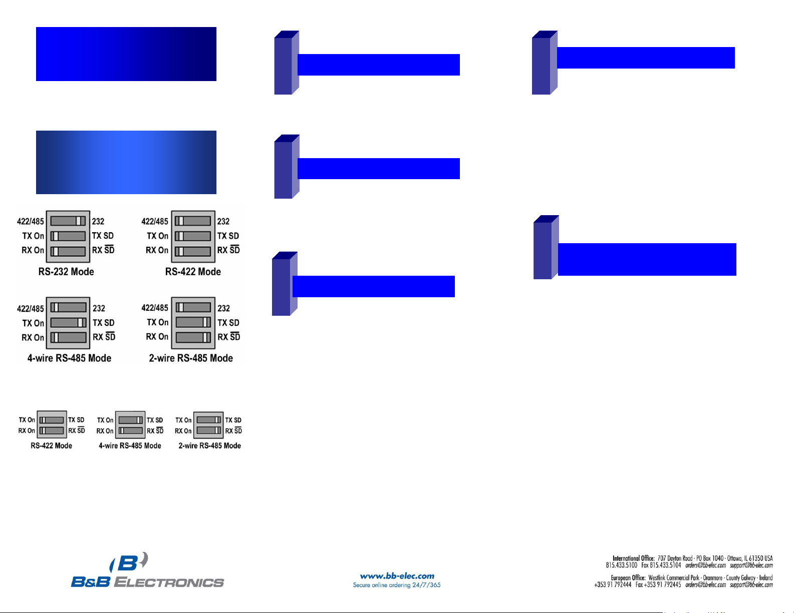
RS-232/422/485 DIP Switch Settings
RS-422/485 DIP Switch Settings
MIPort™ Universal PCI Cards
Models: 3PCIU2, 3PCIU4, 3PCIU8
3PCIOU1, 3PCIOU2, 3PCIOU4
Quick Start Guide
□ Caution: Ensure your PC is powered OFF before
installing the MIPort™ PCI Card.
□Caution: Use ESD Precautions for safe handling.
□Configure the serial mode for each port. DIP Switch
settings are shown on the left. Refer to the manual for
detailed information.
□Install the MIport™ in a PCI Expansion Slot.
□ MIPort™ Universal PCI Card
□ Printed version of this Quick Start Guide
□ CD ROM containing software and a comprehensive manual
□ Depending on model, a cable and/or expansion slot bracket
may be included. Refer to the MIPort Datasheet.
CChheecckk PPaacckkaaggee CCoonntteenntt
HHaarrddwwaarree IInnssttaallllaattiioonn
DDrriivveerr IInnssttaallllaattiioonn
SSeettttiinngg DDaattaa RRaattee // RRTTSS CCoonnttrrooll
□ In Windows, open the System Properties dialog box.
□ On the Hardware Tab, select Device Manager.
□ Expand the Ports List (COM & LPT), double click
the name of the port you want to configure.
□ On the Port Properties dialog box, click the Port
Settings tab.The dialog box will display the current
settings for bits per second, data bits, parity, stop bits
and flow control.
□ Click Advanced. The Advanced Port Settings dialog
box will appear. Under RTS Control, click Normal for
RS-232 Mode and RS-485 Mode for RS-485 Mode.
RTS Control can be in either mode for RS-422.
□ Read this entire section before continuing.
□ Boot the PC.
□ Insert the driver CD. The CD contains drivers for
Windows 98, ME, NT 4.0, 2K, 2003 Server, XP, Vista, and
Linux 2.4
□ Wait until the new hardware is detected and follow the
instructions in the Add New Hardware Wizard.
NOTE: Drivers are contained on the CD. Do not have
Windows attempt to locate them on the Windows Web
Site.
NOTE: A dialog box may appear stating that the
drivers do not contain the Windows XP Logo. Select
“Continue Anyway.”
NOTE: Drivers will be installed for the card AND each
port on the card. DO NOT ABORT OR CANCEL
INSTALLATION BEFORE ALL PORTS ARE
INSTALLED.
TTeessttiinngg tthhee MMIIppoorrtt PPCCII ccaarrddss
RRSS--223322
See Chapter 9 and Appendix C of the manual for more
details.
□ Create loopback plugs or short TD and RD on RS-
232 connector for each port. See step 8 for pinout.
□ Install and run Comtest (included with the CD).
□ Open the COM number that was created in step 3
for each port and send data.
□ If you are able to receive data, installation is
complete. If not, double check the installation.
Documentation Number 3PCI-MIPort -0712qsg PN6411-rev002
Page 2
6
7
TTeessttiinngg tthhee MMIIppoorrtt PPCCII ccaarrddss
RRSS--442222 // 44--wwiirree RRSS--448855
See Chapter 9 and Appendix C of the manual for more
details.
□ Connect TD(A) to RD(A) and TB(B) to RD(B). See
step 9 for pinout.
□ Install and run Comtest (included with the CD).
□ Open the COM number that was created in step 3
for each port and send data.
□ If you are able to receive data, installation is
complete. If not, double check the installation.
TTeessttiinngg tthhee MMIIppoorrtt PPCCII ccaarrddss
22--WWiirree RRSS--448855
See Chapter 9 and Appendix C of the manual for more
details.
□ Install Comtest (included with the CD).
□ For multi-port models, cross connect one port to
another and run separate instances of Comtest for
each port. If you are able to send and receive data,
installation is complete. If not, double check the
installation.
□ For the single-port model, communicate with an
external device or test the port in RS-232 or RS422/485 4-wire mode.
8
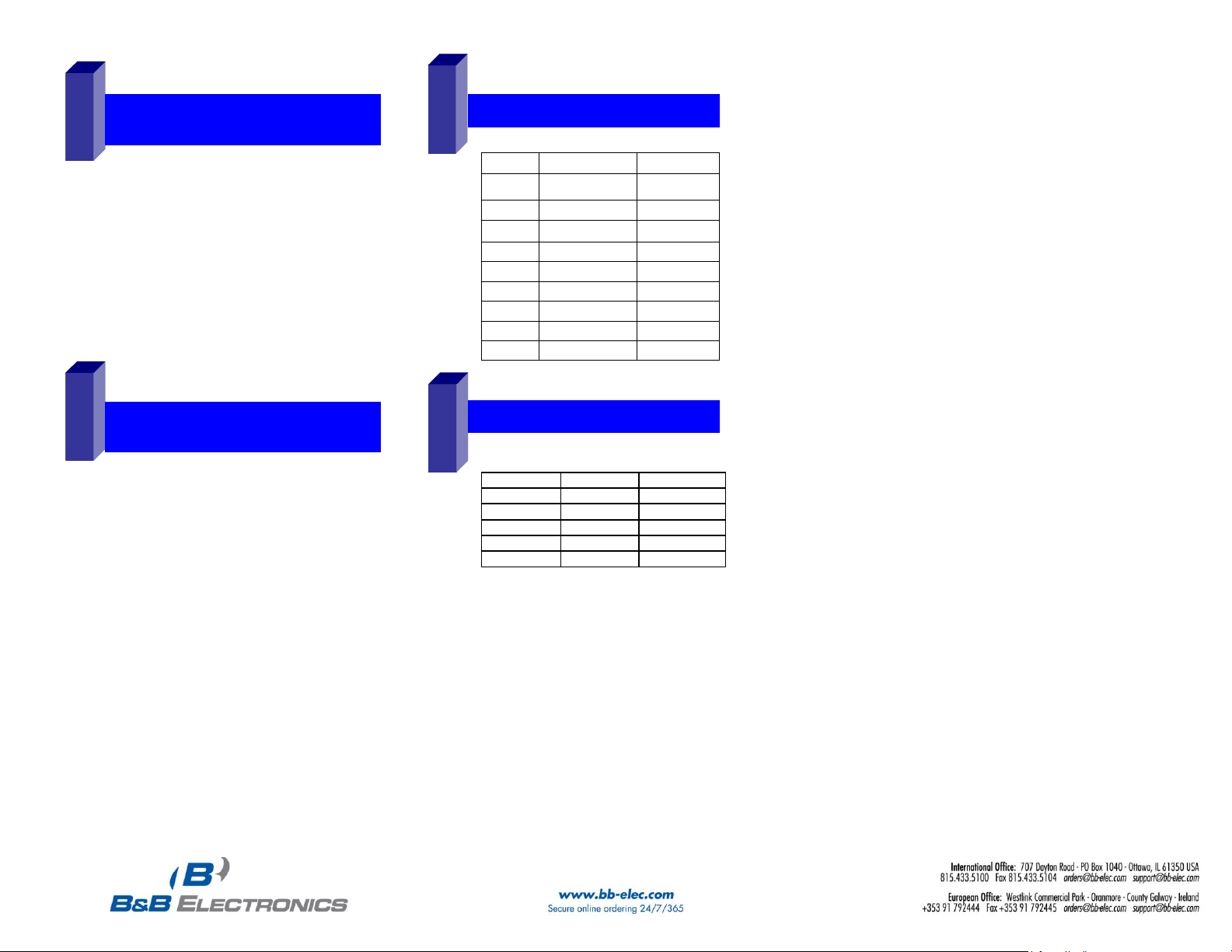
RRSS--223322 PPiinnoouutt ((DDTTEE))
Name
Direction
DB9M Pin
DCD
Input
1
RD
Input
2
TD
Output
3
DTR
Output
4
GND
------
5
DSR
Input
6
RTS
Output
7
CTS
Input
8
RI
Input
9
9
RRSS--442222//448855 PPiinnoouutt
Name
Direction
DB-9M Pin
RD(A) −
Input
1
TD(B) +
Output
2
TD(A) −
Output
3
GND
------
5
RD(B) +
Input
9
Documentation Number 3PCI-MIPort -0712qsg PN6411-rev002
 Loading...