

Page 1

Dual-Port Multi-Interface
(RS-232/RS-422/RS-485)
PCI Bus Serial Card
with Send Data Control
Model: 3PCI2
Documentation Number 3PCI2-0903
This product designed and manufactured in Ottawa, Illinois USA
of domestic and imported parts by
International Headquarters
B&B Electronics Mfg. Co. Inc.
707 Dayton Road -- P.O. Box 1040 -- Ottawa, IL 61350 USA
Phone (815) 433-5100 -- General Fax (815) 433-5105
Orders e-mail: orders@bb-elec.com
Technical Support e-mail: support@bb.elec.com
Home Page: www.bb-elec.com
-- Fax (815) 433-5109
-- Fax (815) 433-5104
European Headquarters
B&B Electronics Ltd.
Westlink Commercial Park, Oranmore, Co. Galway, Ireland
Phone +353 91-792444 -- Fax +353 91-792445
Home Page: www.bb-europe.com
Orders e-mail: orders@bb-europe.com
Technical Support e-mail: support@bb-europe.com
2003 B&B Electronics
Documentation Number 3PCI2-0903 Manual Cover Page
B&B Electronics Mfg Co – 707 Dayton Rd - PO Box 1040 - Ottawa IL 61350 - Ph 815-433-5100 - Fax 815-433-5104
B&B Electronics Ltd – Westlink Comm. Pk. – Oranmore, Galway, Ireland – Ph +353 91-792444 – Fax +353 91-792445
Page 2

2003 B&B Electronics. No partof this publication may be reproduced ortransmitted in any form or by any
means, electronicor mechanical, including photography, recording, or anyinformation storage and retrieval
system withoutwritten consent. Informationin this manual is subject to changewithout notice, and does not
represent acommitment on the part of B&B Electronics.
B&B Electronicsshall not be liable for incidental orconsequential damages resulting from the furnishing,
performance, oruse of this manual.
All brandnames used in this manual are theregistered trademarks of their respective owners. The use of
trademarks orother designations in this publication is forreference purposes only and does not constitutean
endorsement bythe trademark holder.
Page 3

TABLE OF CONTENTS
CHAPTER 1: GENERAL INFORMATION......................................1
I
NTRODUCTION........................................................................................1
F
EATURES................................................................................................ 1
Q
UICK START ..........................................................................................2
S
PECIFICATIONS ......................................................................................3
CHAPTER 2: SETUP.......................................................................... 5
I
NSPECTION .............................................................................................5
B
EFORE STARTING… ..............................................................................5
S
ELECTION OF OPERATING MODE ..........................................................6
J
UMPER/MODE TABLES FOR RS-232/422/485 ........................................6
I
NSTALL THE CARD..................................................................................7
CHAPTER 3: SOFTWARE DRIVER INSTALLATION ..................9
W
INDOWS 95 OR 98 ................................................................................8
S
ET DTR OPERATION............................................................................ 13
C
HANGING COM PORT NUMBER............................................................14
R
EMOVAL OF DRIVERS/CARD ...............................................................17
W
INDOWS 2000 PROFESSIONAL............................................................19
W
INDOWS XP PROFESSIONAL ..............................................................25
S
YSTEM PROPERTIES/HARDWARE/DEVICE MANAGER..........................30
S
ET DTR OPERATION............................................................................ 32
C
HANGING COM PORT NUMBER............................................................33
R
EMOVAL OF DRIVERS/CARD ...............................................................35
S
HOW HIDDEN FILES AND FOLDERS......................................................37
CHAPTER 4: SETTING DRIVER OPTIONS................................. 39
DTR O
PERATION...................................................................................39
A
DVANCED - COM PORT RENAMING ..................................................... 40
D
ATA RATE 1X/4X CLOCK SPEED........................................................41
FIFO S
ETTINGS ..................................................................................... 41
CHAPTER 5: RS-232 CONNECTIONS/OPERATION...................45
RS-232 P
RS-232 O
DTR O
INOUTS ...................................................................................45
PERATION ..............................................................................45
PERATION IN RS-232 MODE ......................................................46
Documentation Number 3PCI2-0903 Manual Table of Contents i
B&B Electronics Mfg Co – 707 Dayton Rd - PO Box 1040 - Ottawa IL 61350 - Ph 815-433-5100 - Fax 815-433-5104
B&B Electronics Ltd – Westlink Comm. Pk. – Oranmore, Galway, Ireland – Ph +353 91-792444 – Fax +353 91-792445
Page 4

CHAPTER 6: RS-422/RS-485 CONNECTIONS/OPERATION.....47
RS-422/485 P
RS-422 & RS-485 D
RS-422 O
RS-485 O
DTR O
RS-485 N
INOUTS............................................................................47
IFFERENTIAL SIGNALS.......................................... 49
PERATION ..............................................................................49
PERATION ..............................................................................50
PERATION IN RS-485 MODE ......................................................50
ETWORK BIASING ..................................................................51
CHAPTER 7: TROUBLESHOOTING.............................................53
APPENDIX A: JUMPER/MODE TABLES...................................A-1
APPENDIX B: CONNECTOR PINOUTS.....................................B-1
APPENDIX C: TROUBLESHOOTING WITH COMTEST.........C-1
APPENDIX D: DECLARATION OF CONFORMITY ................. D-1
ii Table of Contents Documentation Number 3PCI2-0903 Manual
B&B Electronics Mfg Co – 707 Dayton Rd - PO Box 1040 - Ottawa IL 61350 - Ph 815-433-5100 - Fax 815-433-5104
B&B Electronics Ltd – Westlink Comm. Pk. – Oranmore, Galway, Ireland – Ph +353 91-792444 – Fax +353 91-792445
Page 5

CAUTION: ELECTROSTATIC SENSITIVE DEVICE
Use ESD precautions for safe handling.
Before removing the card from the anti-static protective packaging:
• Discharge any static electricity buildup on your body by
touching a large grounded metal surface or the metal
chassis on equipment connected to earth ground by a 3-wire
power cord.
• Avoid touching the gold connectors or other parts on the
card except as necessary to set the configuration jumpers.
• Remove AC power from the computer before inserting the
card.
• Retain the ESD bag for handling the card.
Documentation Number 3PCI2-0903 Manual Table of Contents iii
B&B Electronics Mfg Co – 707 Dayton Rd - PO Box 1040 - Ottawa IL 61350 - Ph 815-433-5100 - Fax 815-433-5104
B&B Electronics Ltd – Westlink Comm. Pk. – Oranmore, Galway, Ireland – Ph +353 91-792444 – Fax +353 91-792445
Page 6

Chapter 1
: General Information
Introduction
The 3PCI2 Dual Port serial interface card is designed to work with
Windows based IBM compatible computers with a PCI bus. The card
is Plug and Play compatible which permits the Windows Operating
System and driver to set the addresses and IRQ used by the card.
If you are developing your own software, make sure that the
communications routines support Windows communication drivers
and a wide range of COM ports (Com1 to Com16 or higher).
Features
• Dual-Port Multiple Interface PC Serial Card
• Windows 95/98/2000/XP Compatible Drivers
• Buffered High Speed 16C950A UARTs (16C550 Compatible)
128 byte FIFOs for input/output with selectable trigger
thresholds
• Supports baud rates to 460.8K baud
• RS-232/422/485 mode independently selectable each port
• RS-232 Mode – All eight signals including DCD & RI
• RS-422 Mode – Supports Transmit & Receive signal pairs
• RS-485 Mode – Supports Transmit & Receive signal pairs for
half or full duplex connections.
• 2-wire or 4-wire RS-485 Operation (Half or Full Duplex)
• Automatic Send Data Control for RS-485 Operation
• Com Port Rename – Advanced Driver Function
• Standard DB9 Male Connectors
Documentation Number 3PCI2-0903 Manual Chapter 1 1
B&B Electronics Mfg Co – 707 Dayton Rd - PO Box 1040 - Ottawa IL 61350 - Ph 815-433-5100 - Fax 815-433-5104
B&B Electronics Ltd – Westlink Comm. Pk. – Oranmore, Galway, Ireland – Ph +353 91-792444 – Fax +353 91-792445
Page 7

Quick Start
CAUTION: ELECTROSTATIC SENSITIVE DEVICE
1. Before removing the card from the anti-static protective
packaging, discharge any static electricity on yourself.
2. Set the Operating Mode Jumpers for each port to match the
mode desired.
3. Unplug the computer Power Cord to prevent accidentally
turning the computer on during installation.
4. Install the Card, replace the cover.
5. Reconnect the Power Cord.
6. While power is off, connect your cables (or wait Step 15).
7. Start the computer (as Administrator 2000/XP).
8. Insert the driver disc in your CD-ROM drive.
9. Wait until new hardware is detected.
10. Proceed with Installation according to your Operating
System. See Chapter 3.
11. Check for new Com ports in Device Manager.
12. Select Driver Settings for DTR Control.
Use the Jumper/Mode Table in Chapter 2.
13. Set Com number as needed.
14. Prepare your cable connections to match the connector
pinouts
. See Chapter 5 (RS-232) or 6 (RS-422 or RS-485).
15. Shut down your computer before connecting the cables.
16. Connect your RS-232 or RS-422/RS-485 cables.
17. Power up your computer.
18. Verify operation of each port with your hardware.
2 Chapter 1 Documentation Number 3PCI2-0903 Manual
B&B Electronics Mfg Co – 707 Dayton Rd - PO Box 1040 - Ottawa IL 61350 - Ph 815-433-5100 - Fax 815-433-5104
B&B Electronics Ltd – Westlink Comm. Pk. – Oranmore, Galway, Ireland – Ph +353 91-792444 – Fax +353 91-792445
Page 8

Specifications
Bus: PCI bus (33MHz/32-bit) +5V bus power.
Slot: Requires one PCI slot
Dimensions: 4.79 x 3.77 in (12.16 x 9.57 cm) card edge
(Mounting bracket: 1.23 x 12.06 x 0.85 cm)
I/O Connections: Two 9-pin male D-sub (DB9M) connectors
OS Supported: Windows 95, 98, 2000, XP
Baud rates: 460.8K baud maximum - RS-232/422/485
UARTs: 16C950 (128-byte FIFO TX and RX buffers)
16C550 compatible
Character length: 5, 6, 7 or 8 bits
Parity: Even, odd or none
Stop bits: 1, 1.5, or 2
RS-232 Data Lines Drivers/Receivers:
Transceiver Device: SP211H (or equivalent)
High level output voltage: 5.0 V minimum
Low level output voltage: −5.0 V minimum
Output current limited to: ±25 mA
Input high threshold voltage: 1.7 V maximum
Input low threshold voltage: 0.8 V minimum
Device will withstand: ±15 V
RS-422/485 Driver/Receiver:
Transceiver Device: SP491 (or equivalent)
Differential driver output voltage: 1.5 - 5 V
Differential input high-threshold voltage: 0.2 V maximum
Differential input low-threshold voltage: −0.2 V minimum
Automatic RS-485 Driver Control Timing:
Driver is enabled by Tx input buffer data. Driver remains
enabled until all data in Tx buffer is sent.
Receiver Biasing:
4.7K pull-up/pull-down for 32 standard (12-15K) nodes
Provision for custom biasing (R14, R13, R16, R17)
Documentation Number 3PCI2-0903 Manual Chapter 1 3
B&B Electronics Mfg Co – 707 Dayton Rd - PO Box 1040 - Ottawa IL 61350 - Ph 815-433-5100 - Fax 815-433-5104
B&B Electronics Ltd – Westlink Comm. Pk. – Oranmore, Galway, Ireland – Ph +353 91-792444 – Fax +353 91-792445
Page 9

Termination: none. Provision for custom termination (R15/18)
Max Power Consumption: All ports loaded
Voltage
(V)
+5
+12
-12
Current
(mA)
240
<1uA -
<1 uA -
Total 240 1.2
Typical Baud Rates
75
110
134
150
300
600
1200
1800
2400
4800
7200
9600
14.4K
19.2K
38.4K
57.6K
115.2K
230.4K
460.8K
Power
(W)
1.2
Any baud rate that is a common divisor of 460.8K can be used if the
application software supports it.
Accessories:
Software: Driver CD-ROM Disc for Windows 95/98/2000/XP
Manual: Instruction Manual (paper copy of this booklet)
4 Chapter 1 Documentation Number 3PCI2-0903 Manual
B&B Electronics Mfg Co – 707 Dayton Rd - PO Box 1040 - Ottawa IL 61350 - Ph 815-433-5100 - Fax 815-433-5104
B&B Electronics Ltd – Westlink Comm. Pk. – Oranmore, Galway, Ireland – Ph +353 91-792444 – Fax +353 91-792445
Page 10

Chapter 2:
Setup
Inspection
Your 3PCI2 serial card was tested for proper operation before
packaging. It should be in perfect mechanical and electrical condition
upon receipt.
CAUTION: ELECTROSTATIC SENSITIVE DEVICE
Use ESD precautions for safe handling.
Before removing the card from the anti-static protective packaging:
• Discharge any static electricity buildup on your body by touching
a large grounded metal surface or the metal chassis on
equipment connected to earth ground by a 3-wire power cord.
• Avoid touching the gold connectors or other parts on the card
except as necessary to set the configuration jumpers.
• Remove AC power from the computer before inserting the card.
• Retain the ESD bag for handling the card.
• Save the packaging for storage or shipping.
Before Starting…
The card is normally pre-configured for RS-232 operation.
Check/Set 3 operating Mode/Jumpers for each port.
Device Driver Setting for RS-485 Mode:
After driver installation, set DTR Operation to RS-485 Mode.
See Chapter 4,
Documentation Number 3PCI2-0903 Manual Chapter 3 5
B&B Electronics Mfg Co – 707 Dayton Rd - PO Box 1040 - Ottawa IL 61350 - Ph 815-433-5100 - Fax 815-433-5104
B&B Electronics Ltd – Westlink Comm. Pk. – Oranmore, Galway, Ireland – Ph +353 91-792444 – Fax +353 91-792445
Setting Driver Options.
Page 11
Selection of Operating Mode
The hardware address and IRQ is set by the Windows Operating
System using driver information files and the Plug and Play OS.
The Operating Mode is set using Jumpers, Device Manager Driver
Settings and by your cable connections and software.
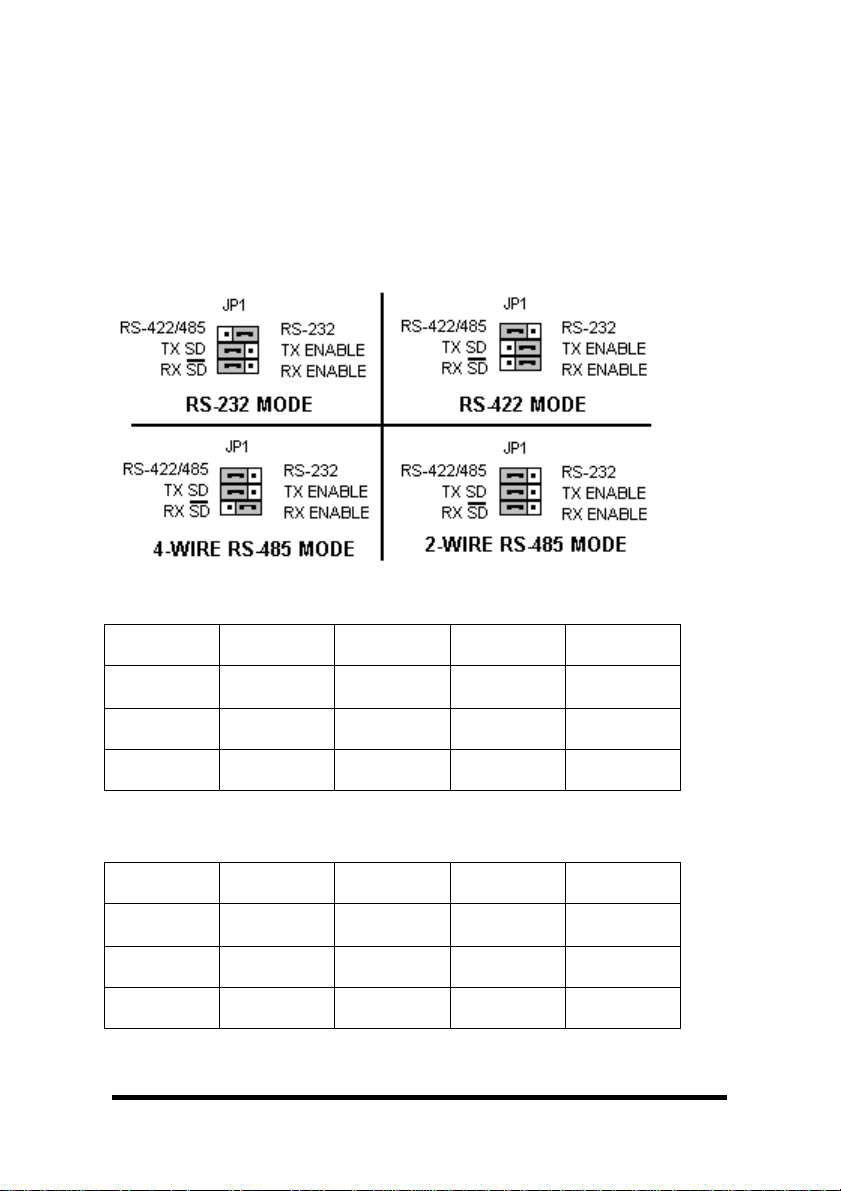
Set the Jumpers
Set JP1 and JP2 Jumpers to match your Operating Mode.
Port 1 (bottom connector)
Port 1
Jumpers
JP1 Top 232
JP1 Middle
JP1 Bottom
Table1–Port1(nearbus)Jumper/ModeTable
RS-232 RS-422
4-Wire
422/485
(Right)
-----
No effect
-----
No effect
(left)
TX ENABLE
(right)
RX ENABLE
(right)
RS-485
4-Wire
422/485
(left)
TX SD
(left)
RX ENABLE
(right)
RS-485
2-Wire
422/485
(left)
TX SD
(left)
RX SD
(left)
Port 2 (top connector
Port 2
Jumpers
JP2 Top 232 422/485
JP2 Middle
JP2 Bottom
RS-232 RS-422
4-Wire
(left)
-----
No effect
-----
No effect
TX ENABLE
(right)
RX ENABLE
(right)
)
RS-485
4-Wire
422/485
(left)
TX SD
(left)
RX ENABLE
(right)
RS-485
2-Wire
422/485
(left)
TX SD
(left)
RX SD
(left)
Table2–Port2(neartopofcard)Jumper/ModeTable
6 Chapter 3 Documentation Number 3PCI2-0903 Manual
B&B Electronics Mfg Co – 707 Dayton Rd - PO Box 1040 - Ottawa IL 61350 - Ph 815-433-5100 - Fax 815-433-5104
B&B Electronics Ltd – Westlink Comm. Pk. – Oranmore, Galway, Ireland – Ph +353 91-792444 – Fax +353 91-792445
Page 12

The top jumper sets DB9 connections for either 232 or 422/485.
RS-232 operation requires setting only the Top jumper.
The middle jumper sets the RS-422/RS-485 transmitter for RS-485
or RS-422 operation
. In RS-485 mode, the transmitter is tri-stated
when not sending data. In RS-422 mode, the transmitter is always
enabled.
The bottom jumper sets the RS-422/RS-485 receiver for half-duplex
RS-485 operation or full-duplex RS-422/RS-485 operation
. In halfduplex RS-485, the receiver is enabled when not transmitting. In
dull-duplex RS-422/485 operation, the receiver is always enabled
.
For more operating mode information, see the related chapter.
Install the Card
1. Shut down your computer.
2. Unplug the power cord to remove power to prevent accidentally
turning on the computer during installation.
3. Remove the cover of the computer.
4. Locate an empty PCI expansion slot.
5. Remove the expansion slot cover. Save the retaining screw.
6. Ground yourself to the computer chassis before and while
inserting the card.
7. Install the card into the unused slot. Be certain that the card is
inserted completely (fully seated) in the slot.
8. Secure the card with the mounting screw from step 5.
9. Replace the cover, plug in the power cord.
10. Connect your cables.
11. Power up the system.
12. Install the drivers as indicated in Chapter 3.
Documentation Number 3PCI2-0903 Manual Chapter 3 7
B&B Electronics Mfg Co – 707 Dayton Rd - PO Box 1040 - Ottawa IL 61350 - Ph 815-433-5100 - Fax 815-433-5104
B&B Electronics Ltd – Westlink Comm. Pk. – Oranmore, Galway, Ireland – Ph +353 91-792444 – Fax +353 91-792445
Page 13
Chapter 3:
Software Driver Installation
Windows 95 or 98
The 3PCI2 drivers are unique to this series of cards. If at some point
in the future, you want to update these drivers, remove these drivers
before installing the new version. See Removal at page 17.
Windows 98 screens are shown for this section. Windows 95 will
have other screen names and text shown. Windows Classic settings
used as standard.
1. Configure each port on card and install it – see Chapter 2.
2. Make sure PnP OS is set in the BIOS. Power up the computer.
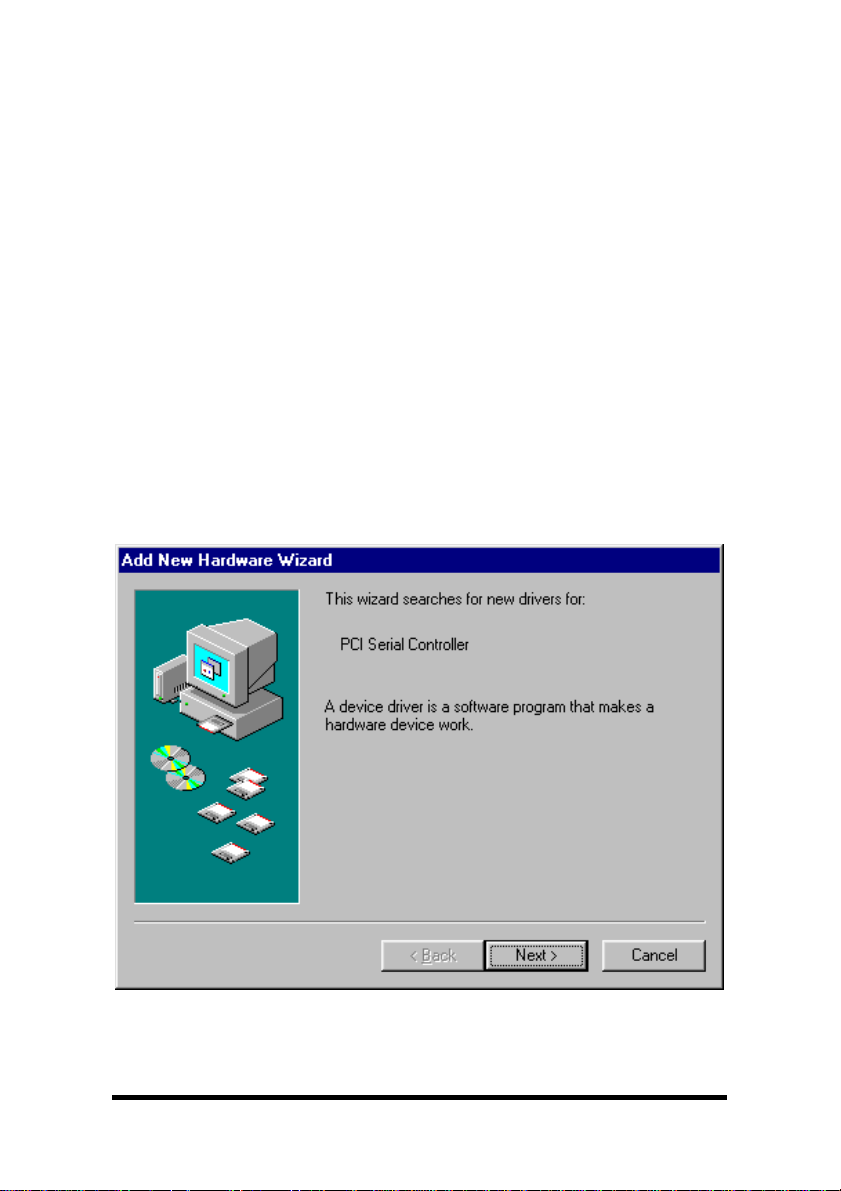
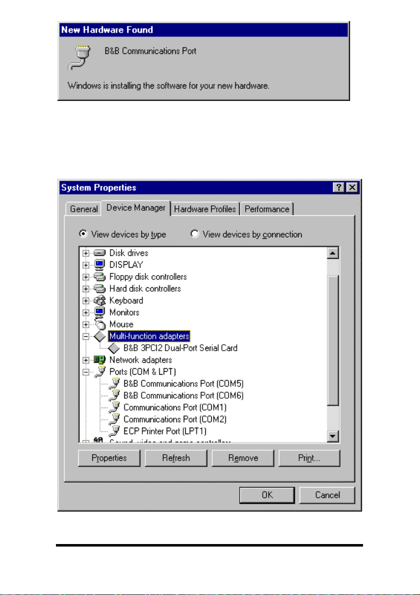
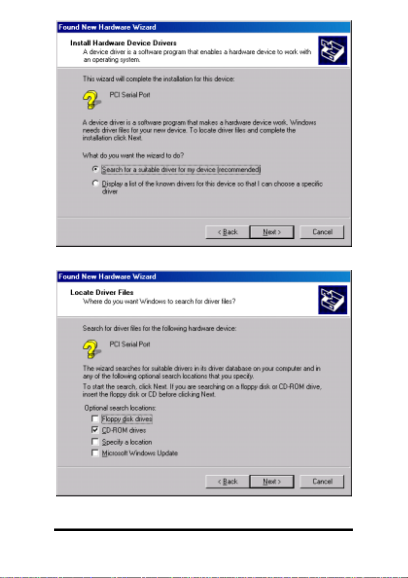
3. Windows will detect the PCI card, start the Add New Hardware
Wizard, and begin driver installation
4. The driver installation goes through several steps after finding
the driver files. The first part installs the driver for the card, then
after Finish, the second part installs the serial driver each Com
port. Do not remove the disc until completed.
5. Click Next.
8 Chapter 3 Documentation Number 3PCI2-0903 Manual
B&B Electronics Mfg Co – 707 Dayton Rd - PO Box 1040 - Ottawa IL 61350 - Ph 815-433-5100 - Fax 815-433-5104
B&B Electronics Ltd – Westlink Comm. Pk. – Oranmore, Galway, Ireland – Ph +353 91-792444 – Fax +353 91-792445
Page 14
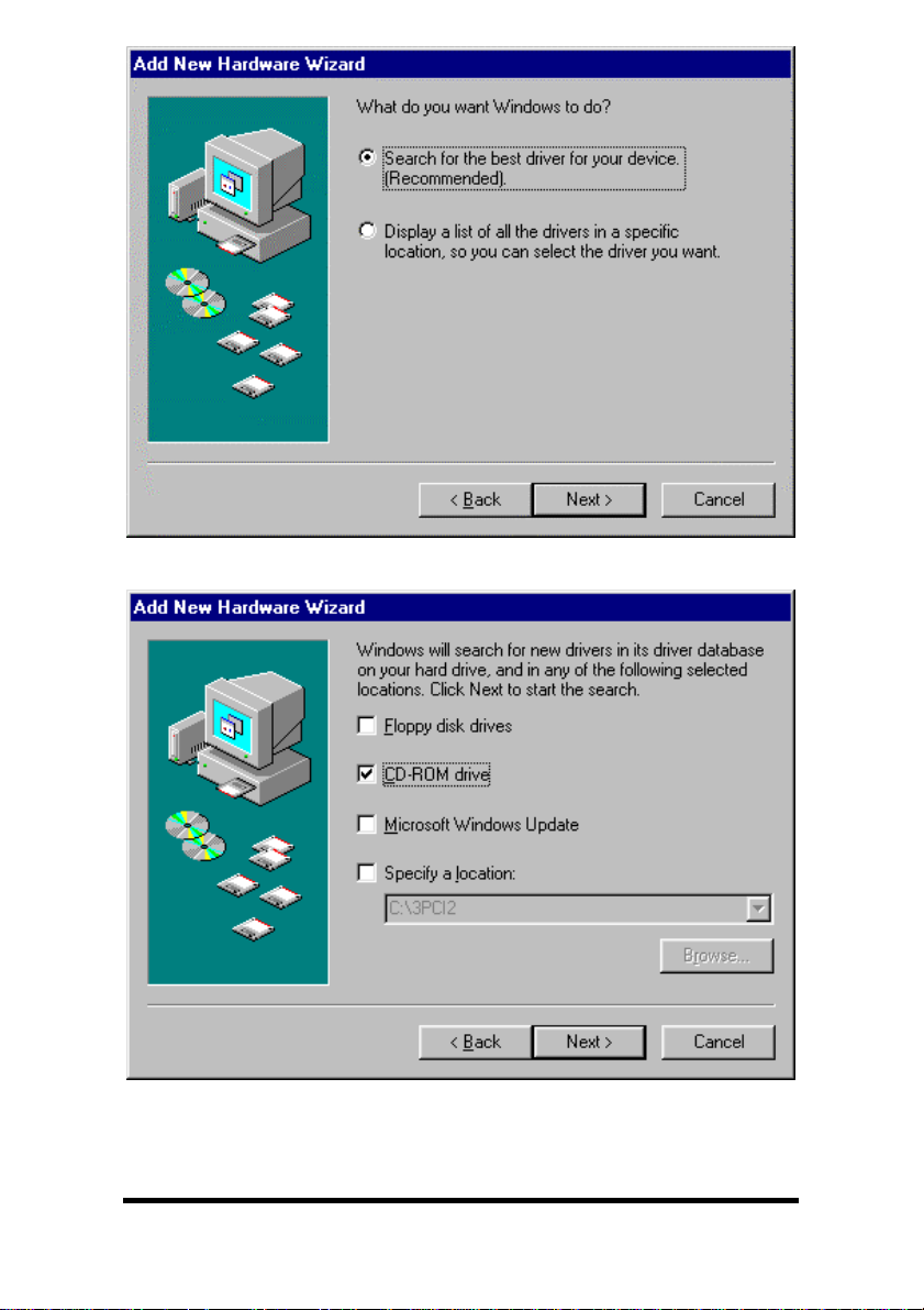
6. Select Search, Click Next.
7. Insert Disc. Select CD-ROM Drive, Click Next.
Documentation Number 3PCI2-0903 Manual Chapter 3 9
B&B Electronics Mfg Co – 707 Dayton Rd - PO Box 1040 - Ottawa IL 61350 - Ph 815-433-5100 - Fax 815-433-5104
B&B Electronics Ltd – Westlink Comm. Pk. – Oranmore, Galway, Ireland – Ph +353 91-792444 – Fax +353 91-792445
Page 15
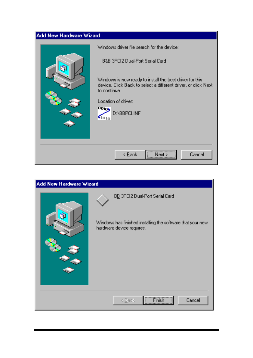
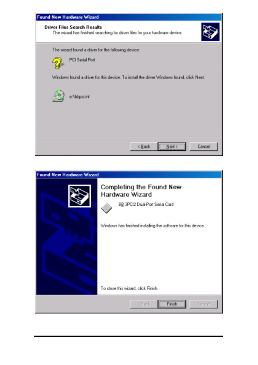
Windows will find “B&B 3PCI2 Dual-Port Serial Card” and the driver
BBPCI.inf file.
8. Click Next.
9. Click Finish. Installation will complete automatically.
10 Chapter 3 Documentation Number 3PCI2-0903 Manual
B&B Electronics Mfg Co – 707 Dayton Rd - PO Box 1040 - Ottawa IL 61350 - Ph 815-433-5100 - Fax 815-433-5104
B&B Electronics Ltd – Westlink Comm. Pk. – Oranmore, Galway, Ireland – Ph +353 91-792444 – Fax +353 91-792445
Page 16
Another similar screen will be shown before the above, and after.
The second time the above is shown, installation will have
completed. Wait for the process to complete.
To verify the installation, open Start, Settings, Control Panel,
System.
Then select the Device Manager Tab.
Documentation Number 3PCI2-0903 Manual Chapter 3 11
B&B Electronics Mfg Co – 707 Dayton Rd - PO Box 1040 - Ottawa IL 61350 - Ph 815-433-5100 - Fax 815-433-5104
B&B Electronics Ltd – Westlink Comm. Pk. – Oranmore, Galway, Ireland – Ph +353 91-792444 – Fax +353 91-792445
Page 17
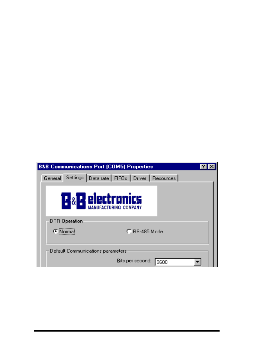
Click the Multifunction adapters view the card. If you want other
details, Select Properties.
Click Ports (COM & LPT) to view the COM numbers assigned by
Windows to the card.
You will have two new B&B com ports as shown (prior page).
Select Properties or double-click on one of the new com ports, to
set driver options.
Set DTR Operation
Set DTR Operation to Normal for RS-232.
Set DTR Operation to RS-485 Mode for2-wireor4-wireRS-485
operation.
Either setting can be used for RS-422.
The card jumpers must be set for the same mode. See Chapter 2.
12 Chapter 3 Documentation Number 3PCI2-0903 Manual
B&B Electronics Mfg Co – 707 Dayton Rd - PO Box 1040 - Ottawa IL 61350 - Ph 815-433-5100 - Fax 815-433-5104
B&B Electronics Ltd – Westlink Comm. Pk. – Oranmore, Galway, Ireland – Ph +353 91-792444 – Fax +353 91-792445
Page 18
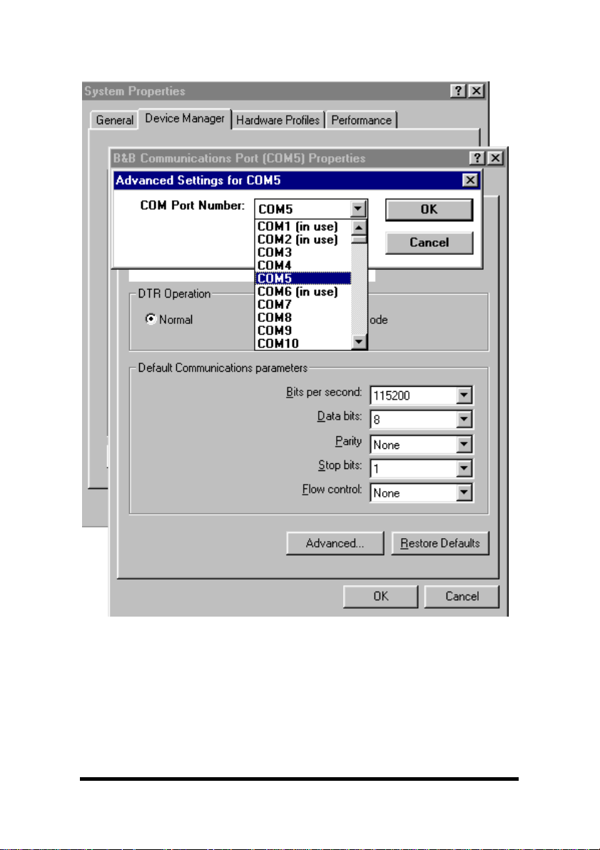
Changing Com Port Number
From the Device Manager, Select Properties, Settings, Advanced.
Available names for Com numbers are shown. Select a new number
from those not “in use”. Com numbers from Com1 to Com256 may
be available. Com numbers “in use” may be used by motherboard
ports, modems, virtual com ports for network serial server devices or
FAX modem. Formerly installed USB to serial adaptors, PCI cards or
other hardware may have reserved a com number. The device may
need to be added back to the system, or the registry may need to be
edited with Reg. Edit or a similar utility.
Documentation Number 3PCI2-0903 Manual Chapter 3 13
B&B Electronics Mfg Co – 707 Dayton Rd - PO Box 1040 - Ottawa IL 61350 - Ph 815-433-5100 - Fax 815-433-5104
B&B Electronics Ltd – Westlink Comm. Pk. – Oranmore, Galway, Ireland – Ph +353 91-792444 – Fax +353 91-792445
Page 19
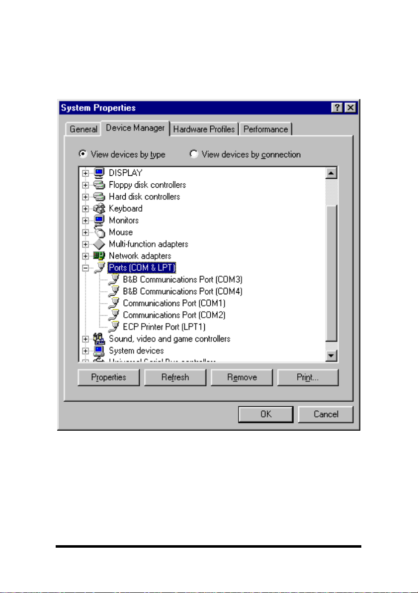
After selecting a new com number, Click OK, then OK again on the
Settings page.
After returning to the Device Manager screen, select Refresh. Then
double-click Ports again.
You should see the two ports renamed as shown below:
Example – After renaming B&B Ports from Com5 and Com6
double-click or select each port to finish selecting other properties.
14 Chapter 3 Documentation Number 3PCI2-0903 Manual
B&B Electronics Mfg Co – 707 Dayton Rd - PO Box 1040 - Ottawa IL 61350 - Ph 815-433-5100 - Fax 815-433-5104
B&B Electronics Ltd – Westlink Comm. Pk. – Oranmore, Galway, Ireland – Ph +353 91-792444 – Fax +353 91-792445
Page 20

The Default Com parameters are normally overridden by the
software application.
Continue in Chapter 4, Setting Driver Options, for Data Rate Clock
Speed and FIFO settings.
Make your connections, RS-232 in Chapter 5, or RS-422/485 in
Chapter 6.
Documentation Number 3PCI2-0903 Manual Chapter 3 15
B&B Electronics Mfg Co – 707 Dayton Rd - PO Box 1040 - Ottawa IL 61350 - Ph 815-433-5100 - Fax 815-433-5104
B&B Electronics Ltd – Westlink Comm. Pk. – Oranmore, Galway, Ireland – Ph +353 91-792444 – Fax +353 91-792445
Page 21
Removal of Drivers/Card
If you need to install a possible future driver update or want to
remove the card from your system:
1. Open My Computer, Control Panel, System (or Start, Setting,
Control Panel, System).
2. Select the Device Manager page.
3. Select the B&B Com port. Click the Remove button.
4. Select the other B&B Com port. Click the Remove button.
5. Click Multifunction Adaptors, then select B&B 3PCI2 Dual-
Port Serial Card which matches the card installed.
6. Click the Remove button.
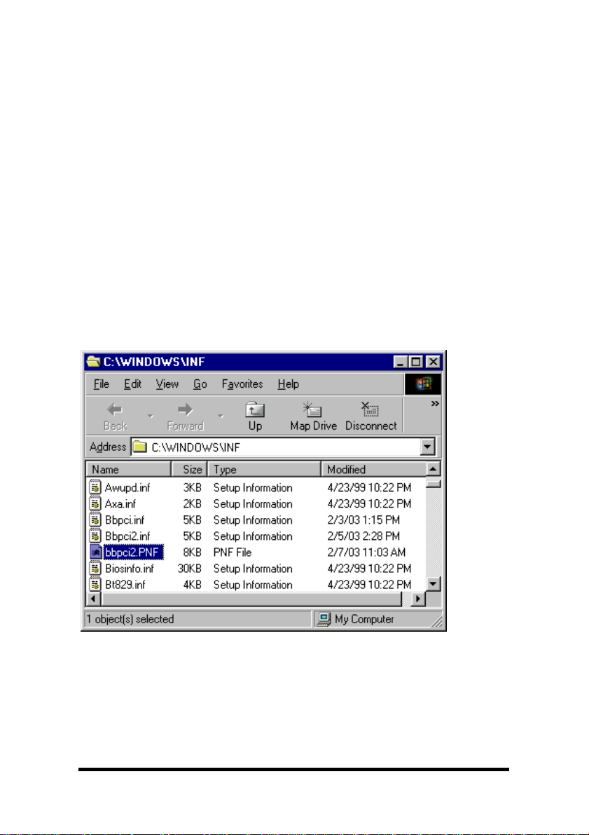
Next find the C:\WINDOWS\INF directory, select View, Details,
Arrange Icons, By Name. (You can use Windows Explorer instead)
7. Find the files, Bbpci.inf, Bbpic2.inf, bbpci2.PNF, and remove
them.
The bbpci2.PNF is a compiled version of the same named .inf and
can be viewed with Notepad if you want to confirm the content
before removing.
16 Chapter 3 Documentation Number 3PCI2-0903 Manual
B&B Electronics Mfg Co – 707 Dayton Rd - PO Box 1040 - Ottawa IL 61350 - Ph 815-433-5100 - Fax 815-433-5104
B&B Electronics Ltd – Westlink Comm. Pk. – Oranmore, Galway, Ireland – Ph +353 91-792444 – Fax +353 91-792445
Page 22
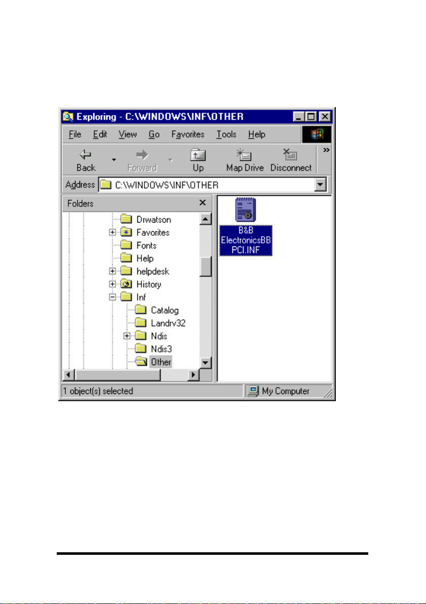
8. Remove Bbpci.inf in Other subdirectory within INF.
If the inf folder can’t be found, select My Computer, View, Folder
Options, Files and Folders, select Show all files.
Removing the card first in the device manager clears the registry.
8. Shut down the computer.
9. Remove the card.
Documentation Number 3PCI2-0903 Manual Chapter 3 17
B&B Electronics Mfg Co – 707 Dayton Rd - PO Box 1040 - Ottawa IL 61350 - Ph 815-433-5100 - Fax 815-433-5104
B&B Electronics Ltd – Westlink Comm. Pk. – Oranmore, Galway, Ireland – Ph +353 91-792444 – Fax +353 91-792445
Page 23

Windows 2000 Professional
This section covers the first part of device driver installation for
Windows 2000 Professional. Windows Classic settings used as
standard.
The 3PCI2 drivers are unique to this series of cards. If at some point
in the future, you want to update these drivers, remove these drivers
before installing the new version. See Removal on page 35.
1. Configure each port on the card for the desired RS-232/422/485
mode using the 3 jumpers for each port. See Chapter 2.
2. Install the card in the slot. Start the computer as Administrator or
ask your system administrator to install the software.
3. Windows will detect the PCI card and start Found New
Hardware Wizard, to begin driver installation
4. Windows 2000 will find new hardware twice. After the driver for
the PCI Serial Card installs, new Com ports will be found and
the serial drivers for the Com ports will be installed.
5. Click Next to continue.
18 Chapter 3 Documentation Number 3PCI2-0903 Manual
B&B Electronics Mfg Co – 707 Dayton Rd - PO Box 1040 - Ottawa IL 61350 - Ph 815-433-5100 - Fax 815-433-5104
B&B Electronics Ltd – Westlink Comm. Pk. – Oranmore, Galway, Ireland – Ph +353 91-792444 – Fax +353 91-792445
Page 24
6. Select Search and Click Next to continue.
7. Insert the driver disc in the CD-ROM drive. Click Next.
Documentation Number 3PCI2-0903 Manual Chapter 3 19
B&B Electronics Mfg Co – 707 Dayton Rd - PO Box 1040 - Ottawa IL 61350 - Ph 815-433-5100 - Fax 815-433-5104
B&B Electronics Ltd – Westlink Comm. Pk. – Oranmore, Galway, Ireland – Ph +353 91-792444 – Fax +353 91-792445
Page 25
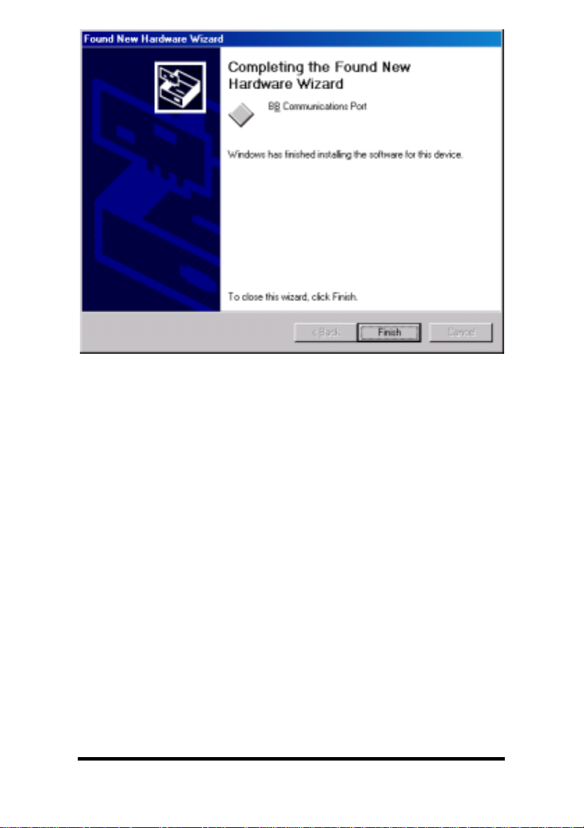
8. Click Next.
9. Click Finish to complete the first part of installation.
20 Chapter 3 Documentation Number 3PCI2-0903 Manual
B&B Electronics Mfg Co – 707 Dayton Rd - PO Box 1040 - Ottawa IL 61350 - Ph 815-433-5100 - Fax 815-433-5104
B&B Electronics Ltd – Westlink Comm. Pk. – Oranmore, Galway, Ireland – Ph +353 91-792444 – Fax +353 91-792445
Page 26

10. Next Windows finds a new type of serial port. Click Next.
1
1. Click Next to search a second time.
Documentation Number 3PCI2-0903 Manual Chapter 3 21
B&B Electronics Mfg Co – 707 Dayton Rd - PO Box 1040 - Ottawa IL 61350 - Ph 815-433-5100 - Fax 815-433-5104
B&B Electronics Ltd – Westlink Comm. Pk. – Oranmore, Galway, Ireland – Ph +353 91-792444 – Fax +353 91-792445
Page 27

12. Select CD-ROM drives. Click Next.
13. Click Next when the bbpci2.inf file is found.
22 Chapter 3 Documentation Number 3PCI2-0903 Manual
B&B Electronics Mfg Co – 707 Dayton Rd - PO Box 1040 - Ottawa IL 61350 - Ph 815-433-5100 - Fax 815-433-5104
B&B Electronics Ltd – Westlink Comm. Pk. – Oranmore, Galway, Ireland – Ph +353 91-792444 – Fax +353 91-792445
Page 28
14. Click Finish.
Wait for the process to complete. Check and verify that a new B&B
Com port is now available.
13. Open Start, Settings, Control Panel, System. Then select the
Hardware tab on System Properties.
14. Skip over the first part of software driver installation for XP which
follows. The second part applies to both 2000 and XP.
Continue on page 30:
Documentation Number 3PCI2-0903 Manual Chapter 3 23
B&B Electronics Mfg Co – 707 Dayton Rd - PO Box 1040 - Ottawa IL 61350 - Ph 815-433-5100 - Fax 815-433-5104
B&B Electronics Ltd – Westlink Comm. Pk. – Oranmore, Galway, Ireland – Ph +353 91-792444 – Fax +353 91-792445
System Properties/Hardware/Device Manager
Page 29

Windows XP Professional
This section covers the first part of device driver installation for
Windows XP Professional. Windows Classic settings used as
standard.
The 3PCI2 drivers are unique to this series of cards. If at some point
in the future, you want to update these drivers, remove these drivers
before installing the new version. See Removal on page 35.
1. Configure each port on the card for the desired RS-232/422/485
mode using the 3 jumpers for each port. See Chapter 2.
2. Install the card in the slot. Start the computer as Administrator or
ask your system administrator to install the software.
3. Windows will detect the PCI card and start Found New
Hardware Wizard, to begin driver installation. Windows XP will
find new hardware three times. After the driver for the PCI Serial
Card installs, the serial driver for each Com port will be installed.
4. Insert your driver disc in the CD-ROM drive.
5. Select Install the software automatically. Allow afew seconds
for the drive to become ready after inserting disc. Click Next.
24 Chapter 3 Documentation Number 3PCI2-0903 Manual
B&B Electronics Mfg Co – 707 Dayton Rd - PO Box 1040 - Ottawa IL 61350 - Ph 815-433-5100 - Fax 815-433-5104
B&B Electronics Ltd – Westlink Comm. Pk. – Oranmore, Galway, Ireland – Ph +353 91-792444 – Fax +353 91-792445
Page 30
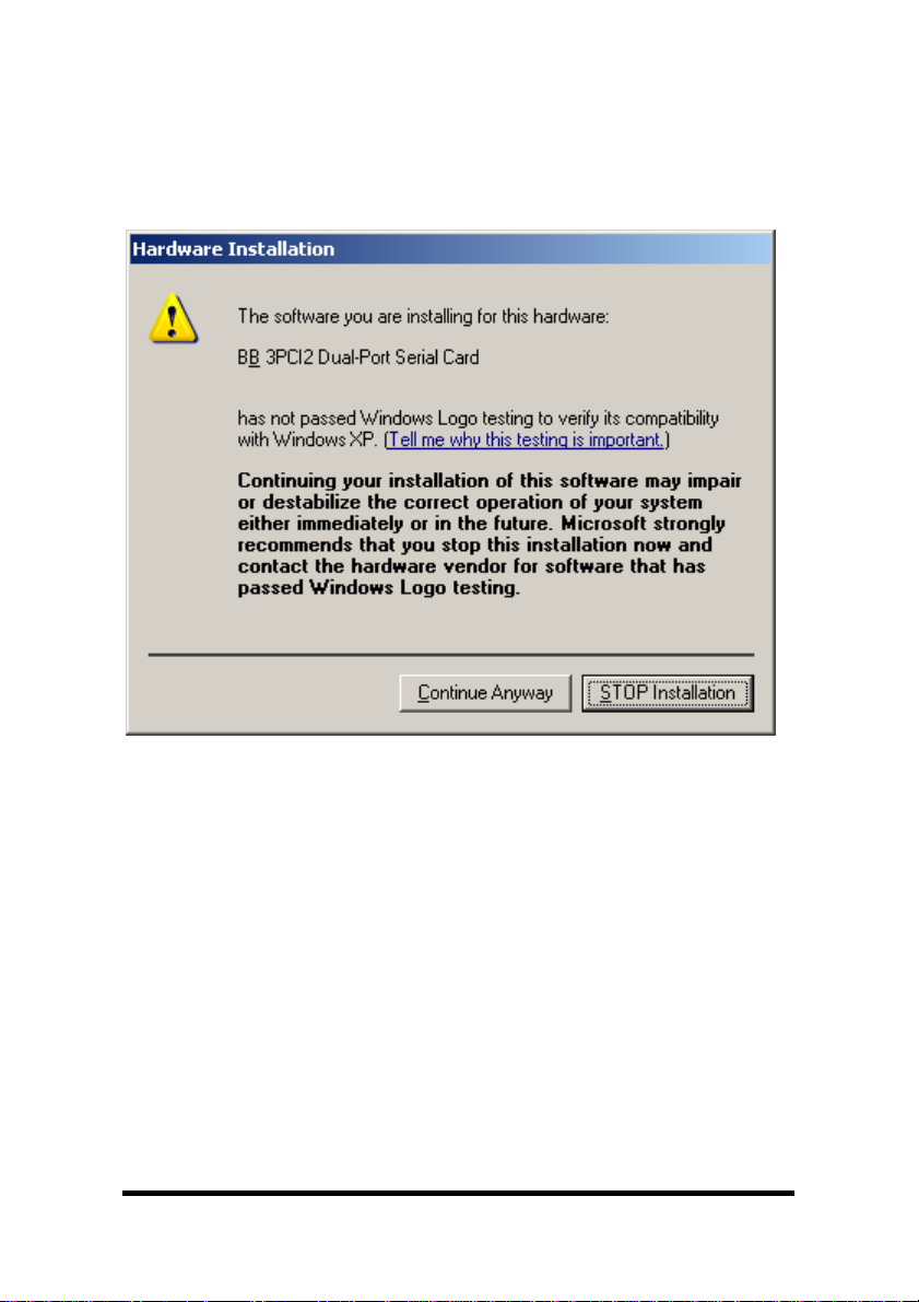
6. Windows will find the drivers on the CD, then provide a notice
concerning Windows Logo testing for XP.
This new feature of XP simply indicates that these drivers have
not yet undergone the Microsoft testing procedures required to
use the Windows XP Logo on the packaging. Driver compatibility
is not affected.
7. Click Continue Anyway.
Continued next page
Documentation Number 3PCI2-0903 Manual Chapter 3 25
B&B Electronics Mfg Co – 707 Dayton Rd - PO Box 1040 - Ottawa IL 61350 - Ph 815-433-5100 - Fax 815-433-5104
B&B Electronics Ltd – Westlink Comm. Pk. – Oranmore, Galway, Ireland – Ph +353 91-792444 – Fax +353 91-792445
Page 31

8. Click Finish to continue installation.
9. Select Next.
26 Chapter 3 Documentation Number 3PCI2-0903 Manual
B&B Electronics Mfg Co – 707 Dayton Rd - PO Box 1040 - Ottawa IL 61350 - Ph 815-433-5100 - Fax 815-433-5104
B&B Electronics Ltd – Westlink Comm. Pk. – Oranmore, Galway, Ireland – Ph +353 91-792444 – Fax +353 91-792445
Page 32

10. Windows provides the Logo notice for Com Port Driver.
11. Click Continue Anyway.
Documentation Number 3PCI2-0903 Manual Chapter 3 27
B&B Electronics Mfg Co – 707 Dayton Rd - PO Box 1040 - Ottawa IL 61350 - Ph 815-433-5100 - Fax 815-433-5104
B&B Electronics Ltd – Westlink Comm. Pk. – Oranmore, Galway, Ireland – Ph +353 91-792444 – Fax +353 91-792445
Page 33

12. Click Finish. Repeat Step 9, 10, 12 for second Com Port.
13. After Finish for the second Com port on the card, this part of
software driver installation is complete.
Check and verify that a new B&B Com port is now available within
the Control Panel, System, Device Manager.
If you are more familiar with Windows 95/98/2000, you may want to
select the Windows Classic look for the Start Menu.
Position the mouse pointer over the Taskbar, then Right Click,
Select Properties.
Select the Start Menu tab, then select Classic Start Menu.
Open Start, Settings, Control Panel, System. Then select the
Hardware tab on System Properties.
Continued next page
28 Chapter 3 Documentation Number 3PCI2-0903 Manual
B&B Electronics Mfg Co – 707 Dayton Rd - PO Box 1040 - Ottawa IL 61350 - Ph 815-433-5100 - Fax 815-433-5104
B&B Electronics Ltd – Westlink Comm. Pk. – Oranmore, Galway, Ireland – Ph +353 91-792444 – Fax +353 91-792445
Page 34

System Properties/Hardware/Device Manager
Select Device Manager, then view the hardware list.
Documentation Number 3PCI2-0903 Manual Chapter 3 29
B&B Electronics Mfg Co – 707 Dayton Rd - PO Box 1040 - Ottawa IL 61350 - Ph 815-433-5100 - Fax 815-433-5104
B&B Electronics Ltd – Westlink Comm. Pk. – Oranmore, Galway, Ireland – Ph +353 91-792444 – Fax +353 91-792445
Page 35

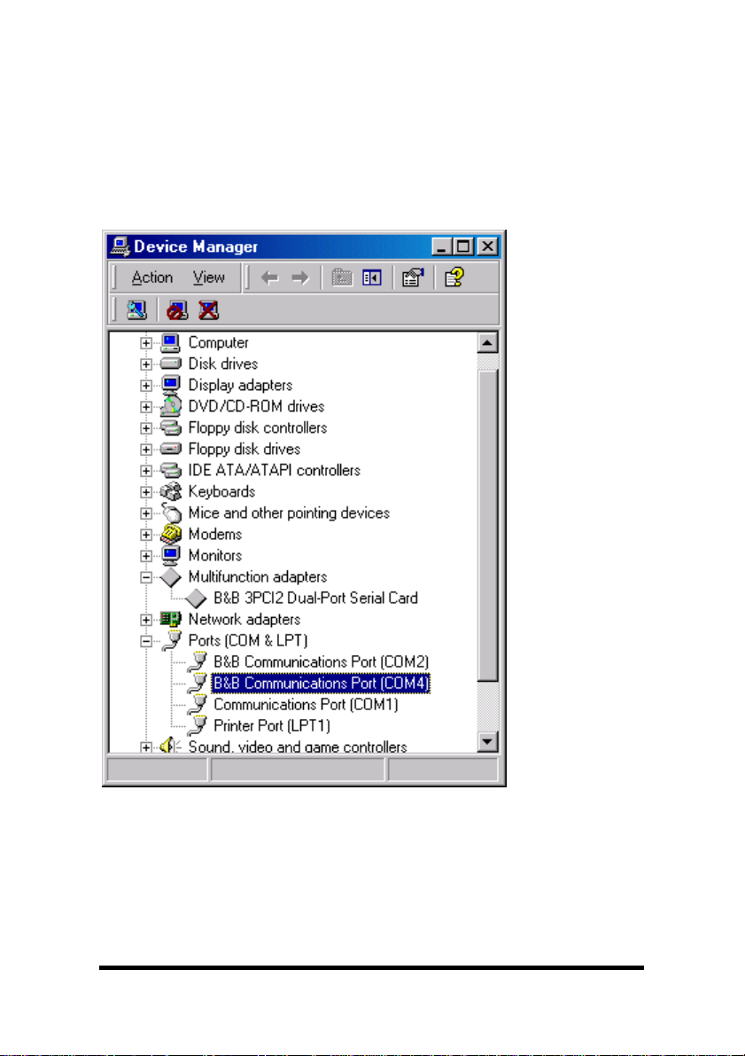
Under Multifunction Adapters, the B&B 3PCI2 Dual-Port Serial
Card is installed.
Under Ports, B&B Com Port (COM6) and (COM7) was assigned.
If Com ports between COM1 and COM6 are not “in use” by other
hardware or software, we can change the B&B Com port to another
available Com number using Properties, Settings, Advanced.
Double-click on COM6 to access the Properties.
Next select Settings.
30 Chapter 3 Documentation Number 3PCI2-0903 Manual
B&B Electronics Mfg Co – 707 Dayton Rd - PO Box 1040 - Ottawa IL 61350 - Ph 815-433-5100 - Fax 815-433-5104
B&B Electronics Ltd – Westlink Comm. Pk. – Oranmore, Galway, Ireland – Ph +353 91-792444 – Fax +353 91-792445
Page 36
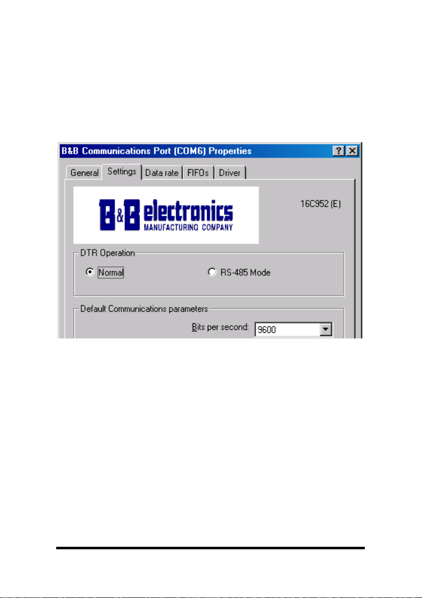
Set DTR Operation
Set DTR Operation to Normal for RS-232.
Set DTR Operation to RS-485 Mode for2-wireor4-wireRS-485
operation.
Either setting can be used for RS-422.
The card jumpers must be set for the same mode. See Chapter 2.
The Default Com parameters are normally overridden by the
software application.
You can now remove the driver disc, close the Windows, and check
the new ports with your software.
Continued next page
Documentation Number 3PCI2-0903 Manual Chapter 3 31
B&B Electronics Mfg Co – 707 Dayton Rd - PO Box 1040 - Ottawa IL 61350 - Ph 815-433-5100 - Fax 815-433-5104
B&B Electronics Ltd – Westlink Comm. Pk. – Oranmore, Galway, Ireland – Ph +353 91-792444 – Fax +353 91-792445
Page 37
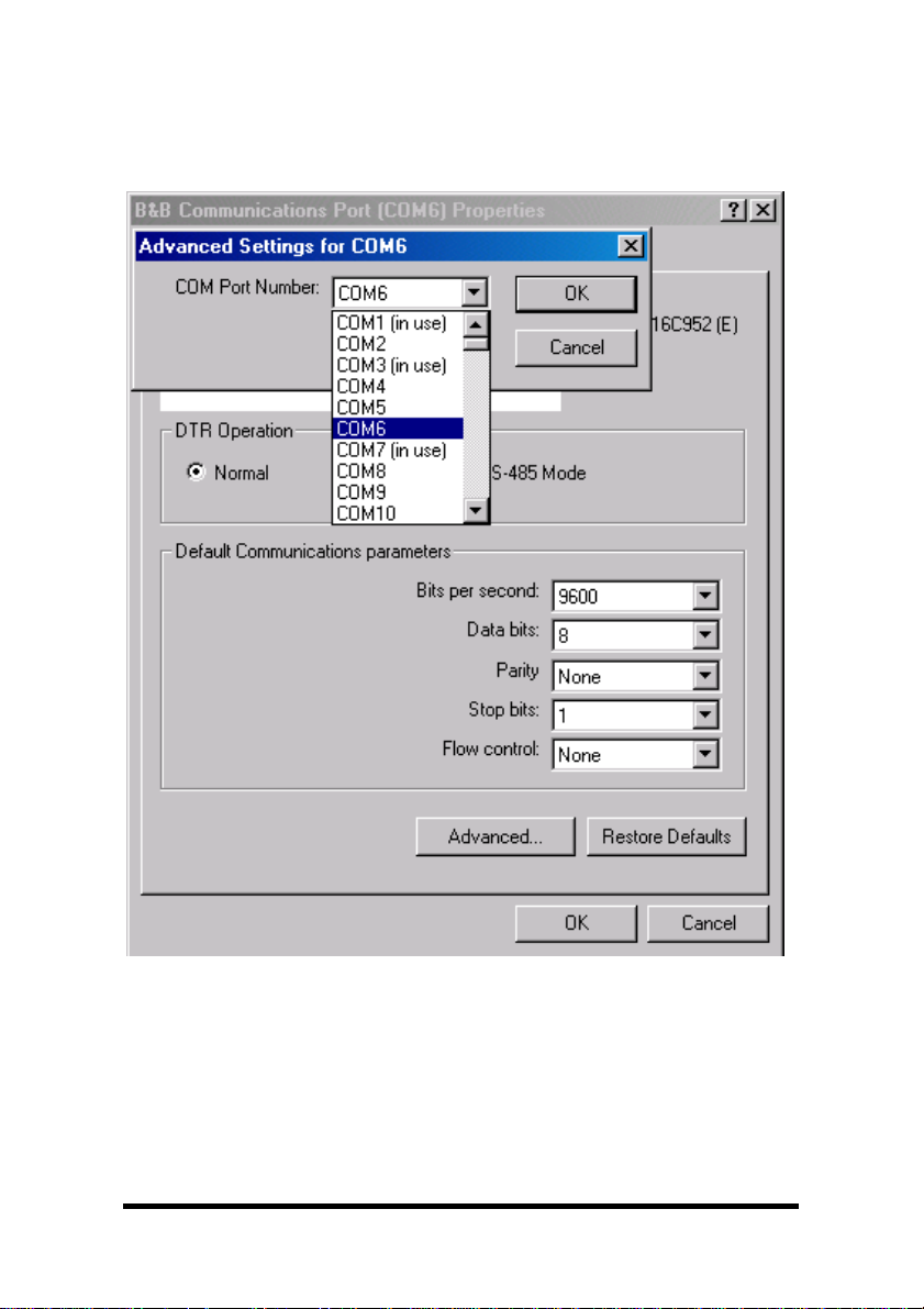
Changing Com Port Number
From the Device Manager, Select Properties, Settings,
Advanced.
Available names for Com numbers are shown. Select a new number
from those not “in use”. Com numbers from Com1 to Com256 may
be available. Com numbers “in use” may be used by motherboard
ports, Modems, virtual com ports for network serial server devices or
FAX modem. Formerly installed USB to serial adaptors, PCI cards or
other hardware may have reserved a com number. The device may
need to be added back to the system, then the software removed.
32 Chapter 3 Documentation Number 3PCI2-0903 Manual
B&B Electronics Mfg Co – 707 Dayton Rd - PO Box 1040 - Ottawa IL 61350 - Ph 815-433-5100 - Fax 815-433-5104
B&B Electronics Ltd – Westlink Comm. Pk. – Oranmore, Galway, Ireland – Ph +353 91-792444 – Fax +353 91-792445
Page 38
Advanced editing of the registry may needed to clean up the
problem. Special permissions are required with 2000 or XP.
After selecting a new com number, Click OK, then OK again on the
Settings page.
After returning to the Device Manager screen, it should refresh
automatically. Then double-click Ports again.
You should see a B&B port renamed as shown below:
Example – After renaming B&B Port to Com2 & Com4
Double-click or select the port to finish selecting other properties.
Continue in Chapter 4, Setting Driver Options
Software installation is complete.
Documentation Number 3PCI2-0903 Manual Chapter 3 33
B&B Electronics Mfg Co – 707 Dayton Rd - PO Box 1040 - Ottawa IL 61350 - Ph 815-433-5100 - Fax 815-433-5104
B&B Electronics Ltd – Westlink Comm. Pk. – Oranmore, Galway, Ireland – Ph +353 91-792444 – Fax +353 91-792445
Page 39

Make your connections, RS-232 in Chapter 5 or RS-422/485 in
Chapter 6.
Removal of Drivers/Card
If you need to install a possible future driver update or want to
remove the card from your system:
1. Click on the B&B Com Port under Ports (COM & LPT) and
select Uninstall (right click).
2. Click on Multifunction Adapters, select the B&B 3PCI2 Dual-Port
Serial Card. Select Uninstall.
This step cleans the entries in the Registry which cannot be
easily edited under 2000 or XP.
3. Remove the two sets of driver files from the Windows INF
directory.
See the screen on the next page
.
(These are named by the OS in the sequence of installation. On
a clean system they are: Oem0.inf & Oem0.PNF and Oem1.inf
& Oem1.PNF. The .inf versions should be verified by opening it
with Notepad, then checking that it is a B&B Electronics file for
the card. The PNF version is a compiled copy of the same
information.)
You can use the Find,
3PCI2,B&B or 3pci
text
File or Folder
within the files.
function to search for the
Windows Explorer can also be used to find the OEM files.
Explorer view shown next page.
You may need to set your Views (under My Computer) to show
all files and folders if the INF directory and .inf files are not
visible. Example after Windows Explorer screen.
4. Shut down the system and remove the card.
34 Chapter 3 Documentation Number 3PCI2-0903 Manual
B&B Electronics Mfg Co – 707 Dayton Rd - PO Box 1040 - Ottawa IL 61350 - Ph 815-433-5100 - Fax 815-433-5104
B&B Electronics Ltd – Westlink Comm. Pk. – Oranmore, Galway, Ireland – Ph +353 91-792444 – Fax +353 91-792445
Page 40

Windows Explorer, WINNT, INF, Oem2 and Oem3 files.
Finding the OEMx.inf and OEMx.PNF files for removal.
Continued next page
Documentation Number 3PCI2-0903 Manual Chapter 3 35
B&B Electronics Mfg Co – 707 Dayton Rd - PO Box 1040 - Ottawa IL 61350 - Ph 815-433-5100 - Fax 815-433-5104
B&B Electronics Ltd – Westlink Comm. Pk. – Oranmore, Galway, Ireland – Ph +353 91-792444 – Fax +353 91-792445
Page 41

Show Hidden Files and Folders
End of Removal section.
36 Chapter 3 Documentation Number 3PCI2-0903 Manual
B&B Electronics Mfg Co – 707 Dayton Rd - PO Box 1040 - Ottawa IL 61350 - Ph 815-433-5100 - Fax 815-433-5104
B&B Electronics Ltd – Westlink Comm. Pk. – Oranmore, Galway, Ireland – Ph +353 91-792444 – Fax +353 91-792445
Page 42

Chapter 4:
Setting Driver Options
DTR Operation
Example - DTR Operation Screen (Windows 98)
Select Normal for RS-232 operation.
Select RS-485 Mode for Automatic RS-485 Driver Control.
Use either setting for RS-422 operation.
Continued next page
Documentation Number 3PCI2-0903 Manual Chapter 4 37
B&B Electronics Mfg Co – 707 Dayton Rd - PO Box 1040 - Ottawa IL 61350 - Ph 815-433-5100 - Fax 815-433-5104
B&B Electronics Ltd – Westlink Comm. Pk. – Oranmore, Galway, Ireland – Ph +353 91-792444 – Fax +353 91-792445
Page 43

Advanced – Com Port Renaming
Select to change port name to another Com number.
From the Device Manager, Select Properties, Settings,
Advanced.
Example - Advanced Settings (Windows 98)
Available names for Com numbers are shown. Select a new number
from those not “in use”. Com numbers from Com1 to Com256 may
be available. Com numbers “in use” may be used by motherboard
ports, Modems, virtual com ports for network serial server devices or
FAX modem. Formerly installed USB to serial adaptors, PCI cards or
other hardware may have reserved a com number.
After selecting a new com number, Click OK, then OK again on the
Settings page.
Continued next page
38 Chapter 4 Documentation Number 3PCI2-0903 Manual
B&B Electronics Mfg Co – 707 Dayton Rd - PO Box 1040 - Ottawa IL 61350 - Ph 815-433-5100 - Fax 815-433-5104
B&B Electronics Ltd – Westlink Comm. Pk. – Oranmore, Galway, Ireland – Ph +353 91-792444 – Fax +353 91-792445
Page 44

Data Rate - 1X or 4X Clock Speed
Each 3PCI2 port in the Device Manager has Data Rate, Clock
Speed settings for normal 1X or 4X.
The 4X position provides a compatibility mode for software which
requires it. In the 4X position, all specified baud rate settings are
multiplied 4 times. For example, if the software specifies 57.6K baud,
the actual baud rate will be 230.4K baud, 115.2K becomes 460.8K
baud. Each port can be set separately.
Example – Data Rate, Clock Speed, 4x (Windows 98)
Refer to Specifications in Chapter 1 for baud rates available.
In many systems, faster baud rates can improve throughput
significantly. Actual throughput and faster baud rates are only
proportional if the system can keep up with the communications,
otherwise increasing the baud rate effectively only increases the idle
time between characters.
Continued next page
Documentation Number 3PCI2-0903 Manual Chapter 4 39
B&B Electronics Mfg Co – 707 Dayton Rd - PO Box 1040 - Ottawa IL 61350 - Ph 815-433-5100 - Fax 815-433-5104
B&B Electronics Ltd – Westlink Comm. Pk. – Oranmore, Galway, Ireland – Ph +353 91-792444 – Fax +353 91-792445
Page 45

FIFO Settings
The default FIFO settings should minimize overhead and work well
for most users.
The FIFO Interrupt Trigger levels setting determines how often the
host processor services the serial port to send or receive data.
The Transmitter Trigger level sets how low the output buffer gets
before it triggers a request for more data from program memory.
The Receiver Trigger level sets how much data is in the input buffer
before it triggers a request to read the data from the buffer to
program memory.
40 Chapter 4 Documentation Number 3PCI2-0903 Manual
B&B Electronics Mfg Co – 707 Dayton Rd - PO Box 1040 - Ottawa IL 61350 - Ph 815-433-5100 - Fax 815-433-5104
B&B Electronics Ltd – Westlink Comm. Pk. – Oranmore, Galway, Ireland – Ph +353 91-792444 – Fax +353 91-792445
Page 46

The optimum setting for each depends on the nature of your data,
how it fits within the buffer, how fast your computer operates, etc.
Receiver FIFO applies when Handshaking is used for Hardware or
Software control.
For Connections, refer to Chapter 5, RS-232 or Chapter 6, RS-422
or RS-485.
Documentation Number 3PCI2-0903 Manual Chapter 4 41
B&B Electronics Mfg Co – 707 Dayton Rd - PO Box 1040 - Ottawa IL 61350 - Ph 815-433-5100 - Fax 815-433-5104
B&B Electronics Ltd – Westlink Comm. Pk. – Oranmore, Galway, Ireland – Ph +353 91-792444 – Fax +353 91-792445
Page 47

Chapter 5:
RS-232 Connections/Operation
The DB-9 male connectors on the card are configured as standard
RS-232 (DTE) serial ports. Table 3 shows the signal names and pin
numbers.
Table 3: RS-232 Pinouts
Name Description Direction
(DTE)
DB9M
Pin
DCD Data Carrier Detect Input 1
RD Receive Data Input 2
TD Transmit Data Output 3
DTR Data Terminal Ready Output 4
GND Signal Ground ------ 5
DSR Data Set Ready Input 6
RTS Request to Send Output 7
CTS Clear to Send Input 8
RI Ring Indicator Input 9
RS-232 Operation
RS-232 signal lines are referenced to Ground and each signal can
alternate above and below ground by the rated voltage (see
Specifications for RS-232 Transmitter/Receiver). Typical input
voltage levels range from -11 to -3 Volts or +3 to +11 Volts.
The primary RS-232 signals are Transmit (Tx) and Receive (Rx), so
together with Ground, they make a “3-wire” interface.
The RTS and CTS signals are Handshaking lines used to indicate to
the other device that data can be sent or received. These lines may
be enabled or disabled on a byte-by-byte basis and are used to
prevent buffer overrun or the loss of data. Auto hardware support.
Two secondary Handshaking signals are DTR and DSR. They are
usually enabled when the device is powered up and the port is open.
They may be used for flow control by some devices instead of RTS
and CTS.
DCD is used by a modem to indicate Carrier to the computer so data
can be sent/received. RI is output by a modem to indicate that the
phone or FAX line has a incoming call, so it can be handled.
42 Chapter 5 Documentation Number 3PCI2-0903 Manual
B&B Electronics Mfg Co – 707 Dayton Rd - PO Box 1040 - Ottawa IL 61350 - Ph 815-433-5100 - Fax 815-433-5104
B&B Electronics Ltd – Westlink Comm. Pk. – Oranmore, Galway, Ireland – Ph +353 91-792444 – Fax +353 91-792445
Page 48

There are two types of RS-232 ports, DTE (Computer) and DCE
(Modem). Connected directly together using a modem cable wired
pin to pin, the inputs match the outputs of the other.
When two of the same type (DTEto DTE or DCE to DCE) are
interconnected, a crossover (null modem) cable is needed to route
the outputs of one to the inputs of the other. This type of cable is
needed to interconnect two computers with RS-232.
RS-232 devices which require hardware handshaking require
connection of RTS/CTS and/or DTR/DSR lines in order to operate
properly.
Programs for RS-232 may chose to use only Receive and Transmit
and ignore hardware handshaking (None) inputs, or may require
connections to verify that a cable and device is ready for access.
Some devices may use Software Handshaking using Xon/Xoff
characters to start and stop the incoming or outgoing data. These
unprintable characters have the value (17) and (19), and can often
be generated in a terminal program with CTL+Q or CTL+S.
DTR Operation In RS-232 Mode
Example – DTR Operation – Select Normal (Windows 98)
In RS-232 mode, the card supports software and hardware
handshaking. For normal DTR Operation select Normal.
Documentation Number 3PCI2-0903 Manual Chapter 5 43
B&B Electronics Mfg Co – 707 Dayton Rd - PO Box 1040 - Ottawa IL 61350 - Ph 815-433-5100 - Fax 815-433-5104
B&B Electronics Ltd – Westlink Comm. Pk. – Oranmore, Galway, Ireland – Ph +353 91-792444 – Fax +353 91-792445
Page 49
Chapter 6:
RS-422/RS-485 Connections/Operation
These modes support 2 channels - transmit and receive. The
pinouts of the DB-9 male connector are given in Table 4.
Table 4: RS-422/485 Pinouts
Name Description Direction DB9M
Pin
RD(A) −−−−
Receive Data A Input 1
TD(B) + Transmit Data B Output 2
TD(A) −−−−
Transmit Data A Output 3
GND Signal Ground ------ 5
RD(B) + Receive Data B Input 9
Connect only to specified pins for proper operation.
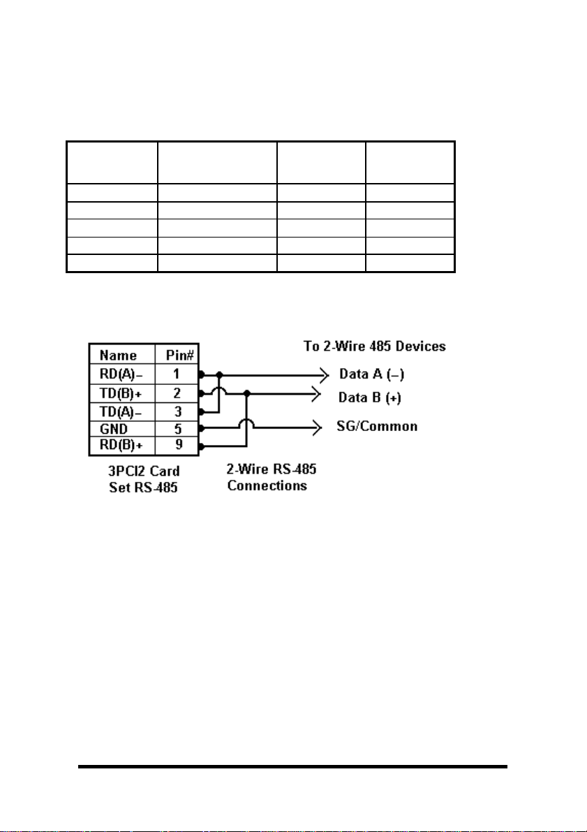
2-Wire RS-485 Connections
Fig. 6.1
2-Wire RS-485: Your cables must bridge pins #1 & #3 and pins #2 &
#9 in order to receive and transmit. Connect from Pin #2 to Data
B(+) of your devices and from pin #3 to Data A(-) of your devices.
Make sure your Mode/Jumpers are set, and that the driver Setting
for DTR Operation is RS-485 Mode in the Device Manager.
Note that the EIA RS-422 Specification labels data lines with an "A"
and "B" designator. Some RS-422 or RS-485 equipment uses a "−"
and "+" designator. In most cases, the "A" line is the equivalent of
the "−" line and the "B" line is the equivalent of the "+" line. Some
device manufacturers may not follow the standard designation for
RS-422 or RS-485, using the A connection for “+” and the B for “-“.
In such cases, reversing the line pair permits operation.
44 Chapter 6 Documentation Number 3PCI2-0903 Manual
B&B Electronics Mfg Co – 707 Dayton Rd - PO Box 1040 - Ottawa IL 61350 - Ph 815-433-5100 - Fax 815-433-5104
B&B Electronics Ltd – Westlink Comm. Pk. – Oranmore, Galway, Ireland – Ph +353 91-792444 – Fax +353 91-792445
Page 50

4-Wire RS-422 or RS-485 Connections
Figure 6.2
Note: With RS-422 Devices, connect only one device to computer.
Connect the TD(B) pin #2 on the computer to RD(B) on the device.
Connect the TD(A) pin #3 on the computer to RD(A) on the device.
Connect the RD(B) pin #9 on the computer to TD(B) on the device.
Connect the RD(A) pin #1 on the computer to TD(A) on the device.
Connect the Signal Ground pin #5 to Signal Ground on the device.
In a 4-wire RS-485 system, each receive line connects to the same
receive terminal on all slaves, and each transmit line connects to the
same transmit terminal on all slaves. The master to the first slave is
connected as above.
In a multi-slave RS-422 connection, TD(B) and TD(A) connect to
RD(B) and RD(A) on all the slaves. If the slaves have Transmit
connections, only one device can be connected back to the master.
See Fig. 6.3 on next page
Documentation Number 3PCI2-0903 Manual Chapter 6 45
B&B Electronics Mfg Co – 707 Dayton Rd - PO Box 1040 - Ottawa IL 61350 - Ph 815-433-5100 - Fax 815-433-5104
B&B Electronics Ltd – Westlink Comm. Pk. – Oranmore, Galway, Ireland – Ph +353 91-792444 – Fax +353 91-792445
.
Page 51

Figure 6.3
RS-422 & RS-485 Differential Signals
In RS-422 and RS-485 modes each signal is differential. When one
line is high (4.4V) the other is low (0V), they alternate voltage with
data. The receiver is differential so that common mode noise picked
up on the twisted pair of wires is cancelled. Receiver sensitivity is
rated at 200mV. A separate signal ground/common connection
provides a common mode reference for the transmitter and receiver.
These factors provide reliable communications at much greater
distances than RS-232.
RS-422 Operation
In RS-422 mode, the transmitter is enabled (TX ENABLE) all the
time, and the receiver is enabled (RX ENABLE) all the time. Typical
connections are for two devices, one device at each end. The
transmit lines of one device are connected to the matching receive
lines of another. The second device transmit lines are connected to
the receive lines of the first.
In another common mode of connection, the transmit lines of the
master device are connected to the receive lines of many listening
slave devices. None of the listening devices reply to the master.
46 Chapter 6 Documentation Number 3PCI2-0903 Manual
B&B Electronics Mfg Co – 707 Dayton Rd - PO Box 1040 - Ottawa IL 61350 - Ph 815-433-5100 - Fax 815-433-5104
B&B Electronics Ltd – Westlink Comm. Pk. – Oranmore, Galway, Ireland – Ph +353 91-792444 – Fax +353 91-792445
Page 52

This limitation is due to the fact that the transmitter is active all the
time, and the line pair is set so that the TD(B) line is high during
Mark state, and the TD(A) line is set low. If another transmitter
output is connected to the same wire pair, and attempts to send data
by setting the line pair to Space state, the first transmitter is still
trying to hold the opposite state and neither can communicate. To
overcome this limitation, the RS-485 mode was established, where
each transmitter tri-states to a high impedance when not
transmitting. See following.
RS-485 Operation
In RS-485 mode the transmit driver must be enabled during transmit
(TX SD) and tri-stated to a high impedance when the data has been
sent. In the 2-wire (half-duplex) mode, the receiver is enabled when
not transmitting, and disabled (RX SD) during transmit (echo off).
The 3PCI2 provides Send Data (SD) Control for the RS-485 Driver
and Receiver. This is hardware controlled based on the contents of
the UART output buffer. When data is present, the driver is enabled,
when the output buffer becomes empty, it is disabled. This
automatically handles whatever baud rate is used.
The RS-485 transmitter and receiver have separate settings for 2wire modes (TX SD, RX SD) or 4-wire (TX SD, RX ENABLE).
Example - Settings, DTR Operation, RS-485 Mode selected.
(Windows 98 shown)
Documentation Number 3PCI2-0903 Manual Chapter 6 47
B&B Electronics Mfg Co – 707 Dayton Rd - PO Box 1040 - Ottawa IL 61350 - Ph 815-433-5100 - Fax 815-433-5104
B&B Electronics Ltd – Westlink Comm. Pk. – Oranmore, Galway, Ireland – Ph +353 91-792444 – Fax +353 91-792445
Page 53

The RS-485 mode is set using 3 jumpers per port, and by selecting
the RS-485 Mode for DTR Operation on that com port.
RS-485 Network Biasing
In an RS-485 network, the transmitter tri-states to a high impedance
state. Unlike RS-422 where the transmitter holds the TD(B) line high
and the TD(A) line low (Mark state) when not transmitting data.
To establish and maintain the Mark state for all RS-485 receivers,
Biasing is required. Biasing maintains a positive voltage difference
from RD(B) relative to RD(A) above the receiver threshold of 200mV
for all devices on that section of the network. If the biasing is not
maintained, the first data bit of a signal may not be detected, and
one or more devices may not respond to commands, or may operate
intermittently.
The RS-485 receivers on the 3PCI2 are biased with a 4.7 KΩ pull-up
resistor on the Receive Data B line and a 4.7 KΩ pull-down resistor
on the Receive Data A line. These values are usually adequate for
networks without termination and 31 or fewer nodes. When
termination is used, biasing must be increased, calculated according
to the termination value and number of nodes. Through-hole pads
are provided for adding smaller value pull-up and pull-down
resistors.
Port 1 (Low: R2/14, Hi: R3/13) R2 = R3 = 4.7K
Port 2 (Low: R4/16, Hi: R5/17) R4 = R5 = 4.7K
Combination of termination and bias must not fall below 54 Ohms.
Termination: Not installed. Not required for baud rates 19.2K or
less.
Port 1 (R15) , Port 2 (R18) R15/R18 • 120 ohms120 ohms
48 Chapter 6 Documentation Number 3PCI2-0903 Manual
B&B Electronics Mfg Co – 707 Dayton Rd - PO Box 1040 - Ottawa IL 61350 - Ph 815-433-5100 - Fax 815-433-5104
B&B Electronics Ltd – Westlink Comm. Pk. – Oranmore, Galway, Ireland – Ph +353 91-792444 – Fax +353 91-792445
Page 54

Chapter 7:
Troubleshooting
If you have any trouble starting your system after installing the card,
the card may not be properly seated in the slot. Remove and reinsert it or try a different slot. Check that BIOS is set for PnP OS.
If you are unable to communicate with the card using your software
and hardware devices:
1. Check your pinouts In RS-422 or RS-485 mode the "A" lines
should match your "A" or "−" lines. "B" lines should match your
"B" or "+" lines.
Note: RS-422/485 pinouts are non-standard.
2. Use the ComTest program provided on the disc with a loopback
to check the card. Double-click on the ComTest folder to open
it.
Documentation Number 3PCI2-0903 Manual Chapter 7 49
B&B Electronics Mfg Co – 707 Dayton Rd - PO Box 1040 - Ottawa IL 61350 - Ph 815-433-5100 - Fax 815-433-5104
B&B Electronics Ltd – Westlink Comm. Pk. – Oranmore, Galway, Ireland – Ph 353-91-792444 – Fax 353-91-792445
Page 55

3. Run Setup.exe to install COMTest on your program menu
under B&B Electronics.
4. Check your Card Jumpers, and Driver Settings. See Chapter 2.
5. Make sure you have DTR Operation set to the correct mode.
Normal for RS-232, RS-485 Mode for RS-485. RS-422 mode
works in either setting provided that the mode jumpers are set
correctly.
6. A loopback connection for RS-232 connects the Transmit
output to the Receive input (pins #2 & #3 on the DB9
connector). Use connections below to check all.
Fig. 7.1 RS-232 Loopback w/Handshaking Connections
7. For RS-422 or 4-wire RS-485, connect the TD(A) toRD(A) and
the TD(B) to RD(B). Then use the COMTest program to send
characters, and observe the characters being received.
Fig. 7.2 RS-422 or 4-wire RS485 Loopback Connections
50 Chapter 7 Documentation Number 3PCI2-0903 Manual
B&B Electronics Mfg Co – 707 Dayton Rd - PO Box 1040 - Ottawa IL 61350 - Ph 815-433-5100 - Fax 815-433-5104
B&B Electronics Ltd – Westlink Comm. Pk. – Oranmore, Galway, Ireland – Ph +353 91-792444 – Fax +353 91-792445
Page 56

Fig. 7.3 RS-485 Connections for 2-Wire Mode
8. To check 2-wire RS-485, you must either enable the receiver
by moving the receive jumper to RX ENABLE mode (Table 1),
or use one port to transmit to another by cross connecting (Fig.
7.3) and loading COMTest twice, one copy for each port.
Characters typed in one copy of COMTest will appear in the
receive window of the other. Note that software must ignore the
RS-232 handshaking lines in RS-422/RS485 mode, the input
lines (CTS, DSR, DCD, RI) are not pulled high.
9. Some manufacturers label their data connections for A and B
reverse of the standard for RS-422 or RS-485, so that the A
line is (+) and B line is inverted (-) following the IC standard. In
such a case, just swap the wires and try it. No damage occurs
in the RS-485 mode, just no devices will respond. The EIA
standard for signal labels defines the B line as positive relative
to A during the “MARK” state.
10. Try another software package for troubleshooting.
11. Check our website for available FAQ's or troubleshooting hints.
12. Contact B&B Electronics Technical Support for troubleshooting
assistance.
USA Office
Technicians are available at (815) 433-5100 to answer your
questions from 8 AM - 5 PM weekdays (Central Time).
Email: <support@bb-elec.com>
European Office
Technicians are available at +353 91 792444 to answer your
questions from 8:30 AM – 5 PM weekdays (GMT Time).
Email: <support@bb-europe.com>
Documentation Number 3PCI2-0903 Manual Chapter 7 51
B&B Electronics Mfg Co – 707 Dayton Rd - PO Box 1040 - Ottawa IL 61350 - Ph 815-433-5100 - Fax 815-433-5104
B&B Electronics Ltd – Westlink Comm. Pk. – Oranmore, Galway, Ireland – Ph 353-91-792444 – Fax 353-91-792445
Page 57

Appendix A
: Jumper/Mode Settings
Set JP1 and JP2 Jumpers to match your Operating Mode.
Port 1 (bottom connector)
Port 1
Jumpers
JP1 Top 232
JP1 Middle
JP1 Bottom
RS-232 RS-422
4-Wire
422/485
(Right)
-----
No effect
-----
No effect
(left)
TX ENABLE
(right)
RX ENABLE
(right)
RS-485
4-Wire
422/485
(left)
TX SD
(left)
RX ENABLE
(right)
RS-485
2-Wire
422/485
(left)
TX SD
(left)
RX SD
(left)
Table A.1 – Port 1 (nearest bus) Jumper/Mode
Port 2 (top connector)
Port 2
Jumpers
JP2 Top 232 422/485
JP2 Middle
JP2 Bottom
RS-232 RS-422
4-Wire
(left)
-----
No effect
-----
No effect
TX ENABLE
(right)
RX ENABLE
(right)
RS-485
4-Wire
422/485
(left)
TX SD
(left)
RX ENABLE
(right)
RS-485
2-Wire
422/485
(left)
TX SD
(left)
RX SD
(left)
Table A.2 – Port 2 (nearest card top) Jumper/Mode
The top jumper sets either 232 or 422/485 DB9 connections.
Only the Top JP1 or JP2 position affects RS-232 mode
.
The middle jumper sets either 485 or 422 transmit enable.
The bottom jumper sets either 485 (half duplex) or receive enable.
Full duplex 4-wire modes must select RX ENABLE.
Documentation Number 3PCI2-0903 Manual Appendix A A –1
B&B Electronics Mfg Co – 707 Dayton Rd - PO Box 1040 - Ottawa IL 61350 - Ph 815-433-5100 - Fax 815-433-5104
B&B Electronics Ltd – Westlink Comm. Pk. – Oranmore, Galway, Ireland – Ph +353 91-792444 – Fax +353 91-792445
Page 58

Appendix B:
Connector Pinouts
Table B.1: RS-232 Pinouts
Name Description Direction
DB9M
(DTE)
DCD Data Carrier Detect Input 1
RD Receive Data Input 2
TD Transmit Data Output 3
DTR Data Terminal Ready Output 4
GND Signal Ground ------ 5
DSR Data Set Ready Input 6
RTS Request to Send Output 7
CTS Clear to Send Input 8
RI Ring Indicator Input 9
Table B.2: RS-232 DB9 to DB25 Conversion Cable
Name DB9 Pin
(DTE)
DB25 Pin
(DTE)
DCD 1 8
RD 2 3
TD 3 2
DTR 4 20
Pin
GND 5 7
DSR 6 6
RTS 7 4
CTS 8 5
RI 9 22
Chassis
GND
Shield
(DB9
1
Shell)
Documentation Number 3PCI2-0903 Manual Appendix B B –1
B&B Electronics Mfg Co – 707 Dayton Rd - PO Box 1040 - Ottawa IL 61350 - Ph 815-433-5100 - Fax 815-433-5104
B&B Electronics Ltd – Westlink Comm. Pk. – Oranmore, Galway, Ireland – Ph +353 91-792444 – Fax +353 91-792445
Page 59

Table B.3: RS-422/485 Pinouts
Name Description Direction DB9M
Pin
RD(A) −−−−
Receive Data A Input 1
TD(B) + Transmit Data B Output 2
TD(A) −−−−
Transmit Data A Output 3
GND Signal Ground ------ 5
RD(B) + Receive Data B Input 9
With 2-wire RS-485 mode operation, your connection cable must
jumper TD(A) to RD(A) and TD(B) to RD(B). Connect from TD(A)
and TD(B) to the Data A(−−−−) and Data B(+) wires of your RS-485
network.
See Chapter 6 for example connections.
Note that the EIA RS-422 Specification labels data lines with an "A"
and "B" designator. Some RS-422 equipment uses a "−" and "+"
designator. In almost all cases, the "A" line is the equivalent of the
"−" line and the "B" line is the equivalent of the "+" line.
More
information on RS-422 communications can be found in the B&B
Electronics RS-422/485 Application Note (available on our
website)
.
B-2 Appendix B Documentation Number 3PCI2-0903 Manual
B&B Electronics Mfg Co – 707 Dayton Rd - PO Box 1040 - Ottawa IL 61350 - Ph 815-433-5100 - Fax 815-433-5104
B&B Electronics Ltd – Westlink Comm. Pk. – Oranmore, Galway, Ireland – Ph +353 91-792444 – Fax +353 91-792445
Page 60

Appendix C:
Troubleshooting With ComTest
Included on the CD-ROM disc is a test program called ComTest.
See Chapter 7.
ComTest is a simple 32-bit Windows (Windows 95, 98, 2000, XP or
NT 4.0) COM port test program. It allows multiple ports at any
address and IRQ, to be opened at any given time.
ComTest can also be found on our Support webpage at:
www.bb-elec.com
.
B&B Com Test
• A Windows Terminal Program for Simple Checks of Serial
Ports. Works with USB Serial Converters & ISA or PCI
Serial Cards.
• Serial Port Access under Windows 95/98/2000/XP – Com1Com8 or above.
• Dual Windows show typed transmit characters in separate
window from received characters.
• Transmit & Receive Activity Indicators.
• Unprintable Characters Shown in Hex – 2 Digits Within Left
& Right Angle Brackets.
• Visual Indication of Handshaking Lines – DTR DSR DCD
and RTS CTS. (Red = Hi)
• Option for Setting DTR or RTS lines high or low.
• Option for Repeat Mode – last character or Function
Character Sequence is repeated until set off.
• Configuration Settings:
- Baud Rates 150, 300, 600, 1200, 2400, 9600, 19.2, 28.4, 57.6,
115.2K (9600 recommended)
- Parity: None, Odd, Even, Mark, Space (None default)
- DataBits:5,6,7,8(8default)
- Stop Bits: 1, 1.5, 2 (1 default)
Documentation Number 3PCI2-0903 Manual Appendix C C-1
B&B Electronics Mfg Co – 707 Dayton Rd - PO Box 1040 - Ottawa IL 61350 - Ph 815-433-5100 - Fax 815-433-5104
B&B Electronics Ltd – Westlink Comm. Pk. – Oranmore, Galway, Ireland – Ph +353 91-792444 – Fax +353 91-792445
Page 61

Start ComTest
1. Make loopback connections.
2. Select Start, Programs, B&B Electronics, ComTest, ComTest.
3. ComTest Starts with a Select Port Window.
4. Select the Com port to access or test. (The drop down box
shows available ports not in use).
5. Click Ok. Configure Port is shown.
6. Select the needed baud rate, parity, data bits, stop bits.
(Defaults are common settings).
7. Type characters – they will appear in the upper window.
8. If performing a loopback test, observe the received characters in
the lower window.
9. Use the Option to set DTR high or low, observe the DSR line
and if connected the DCD line follow. (RS-232 only)
10. Use the Option to set the RTS line high or low, observe the CTS
input line follow. (RS-232 only)
Exit
When testing is completed, close the program.
C-2 Appendix C Documentation Number 3PCI2-0903 Manual
B&B Electronics Mfg Co – 707 Dayton Rd - PO Box 1040 - Ottawa IL 61350 - Ph 815-433-5100 - Fax 815-433-5104
B&B Electronics Ltd – Westlink Comm. Pk. – Oranmore, Galway, Ireland – Ph +353 91-792444 – Fax +353 91-792445
Page 62

Appendix D: Declaration of Conformity Statement
Manufacturer’s Name: B&B Electronics Manufacturing Company
Manufacturer’s Address: P.O. Box 1040
Model Numbers: 3PCI2
Description: 2-port RS232/422/485 PCI Serial Card
Type: Light industrialITE equipment
Application ofCouncil Directive: 89/336/EEC
Standards: EN 55022
William H.Franklin III, Director of Engineering
DECLARATION OF CONFORMITY
707 DaytonRoad
Ottawa, IL 61350 USA
EN 50082-1
EN 61000(-4-2, -4-3, -4-4, -4-6)
Documentation Number 3PCI2-0903 Manual Appendix D D–1
B&B Electronics Mfg Co – 707 Dayton Rd - PO Box 1040 - Ottawa IL 61350 - Ph 815-433-5100 - Fax 815-433-5104
B&B Electronics Ltd – Westlink Comm. Pk. – Oranmore, Galway, Ireland – Ph +353 91-792444 – Fax +353 91-792445
 Loading...