

Page 1

1
300 Series
Media Converter &
Industrial Ethernet Switches
Installation
Guide
(Revised 8/4/2009)
Page 2
2
Industrial Eth e rne t Swit c h Inst a ll ati on G u ide
302MC-XX
302MCE-XX-YY
304TX
305FX-XX
305FXE-XX-YY
306TX
306FX2-XX
306FXE2-XX-YY
308TX
Where: XX = ST or SC and YY = -15, -40, or -80
(Revised 8/4/2009)
Page 3
3
Copyright, © N-TRON Corp., 2008
820 S. University Blvd., Suite 4E
Mobile, AL 36609 USA
All rights reserved. Reproduction, adaptation, or translation without prior written permission from N-TRON
Corp. is prohibited, except as allowed under copyright laws.
Ethernet is a registered trademark of Xerox Corporation. All other product names, company names, logos
or other designations mentioned herein are trademarks of their respective owners.
The information contained in this document is subject to change without notice. N-TRON Corp. makes no
warranty of any kind with regard to this material, including, but not limited to, the implied warranties of
merchantability or fitness for a particular purpose. In no event shall N-TRON Corp. be liable for any
incidental, special, indirect, or consequential damages whatsoever included but not limited to lost profits
arising out of errors or omissions in this manual or the information contained herein.
Warning
Do not perform any services on the unit unless qualified to do so. Do not substitute unauthorized parts or
make unauthorized modifications to the unit.
Do not operate the unit with the top cover removed, as this could create a shock or fire hazard.
Do not block the air vents on the sides or the top of the unit.
Do not operate the equipment in the presence of flammable gasses or fumes. Operating electrical equipment
in such an environment constitutes a definite safety hazard.
(Revised 8/4/2009)
Page 4
4
Safety Warnings
ELECTRICAL SAFETY
WARNING: Ex plosion hazard, do not disconnect while circuits is live unless area is known to be non-
hazardous.
WARNING: Disconnect the power cable before removing the enclosure top.
WARNING: Do not operate the unit with the top cover removed.
WARNING: Do not work on equipment or cables during periods of lightning activity.
WARNING: Do not perform any services on the unit unless qualified to do so.
WARNING: Do not block the air vents.
WARNING: Observe proper DC Voltage polarity when installing power input cables. Reversing
voltage polarity can cause permanent damage to the unit and void the warranty.
Power must be supplied by an isolating source, and a 3.3 A maximum rated UL Recognized fuse
must be installed immediately before the unit.
LASER SAFETY (FXE Products Only)
CAUTION: CLASS 1 LASER PRODUCT. Do not stare into the laser!)
(Revised 8/4/2009)
Page 5

5
Hazardous Location Installation Requirements
1. WARNING: Do not disconnect while circuit is live, unless area is known to be non-hazardous.
2. WARNING: Install only in accordance with Local & National Codes of Authorities Having Jurisdiction.
3. Class I, Div 2 Installations require that power connections must be current limited at the power source with
an in-line fuse rated at 0.5A.
4. Class I, Div 2 installations require that all devices connected to this product must be UL approved for the
area in which it is installed.
5. Only UL approved wiring with temperature ratings greater than 90°C permitted for Class I, Div 2
installations operating at temperatures up to70°C ambient.
6. Limited Operating Voltage: 12-30V for Class I, Div 2 installations.
(Revised 8/4/2009)
Page 6

6
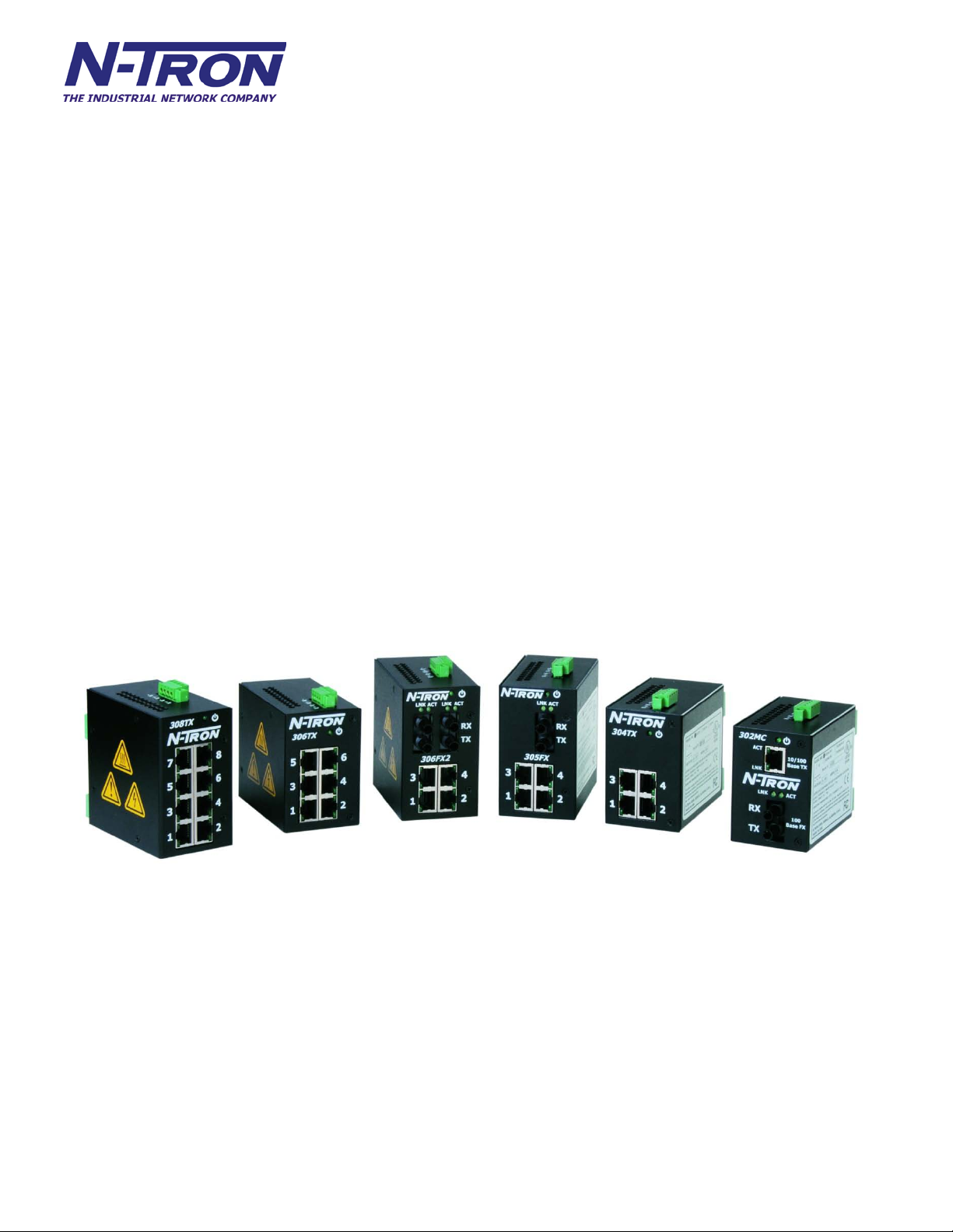
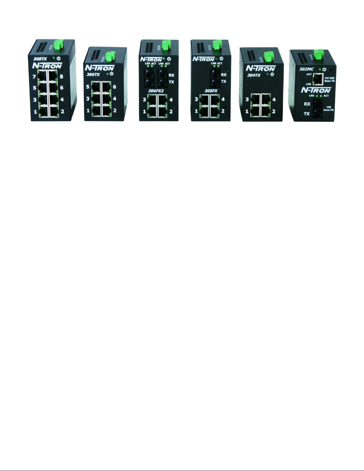
300 Series Industrial Ethernet Switches
The 300 Series Unmanaged Industrial Ethernet Switches support high speed layer 2 switching between
ports. All N-TRON 300 Series switches ar e housed in a ru ggedized steel enclosure, and provide Ca tegor y-5
compliant 10/100-BaseT connections for high performance network design, and hub/repeater upgrades.
The 302MC/MCE is a 2 port unmanaged media converter that converts 10/100BaseTX copper to
100BaseFX full duplex fiber.
The 304TX, 306TX, and 308TX are affordable and share a small footprint. Each swi tch is capable of auto
negotiating 10/100 Mb and half/full duplex communications.
The 305FX and 306FX2 switches are unmanaged and have 4 ports similar to the 304TX, plus an additional
multimode fiber optic up-link port(s), capable of 2 Kilometers of 100 Mb communications without the use
of repeaters.
The 305FXE and 306FXE2 swit ches are unmanaged and similar to the 305FX and 306FX2, respectively.
However, these models use singlemode transceivers with extended range capability. The N-TRON FXE
products utilize singlemode fiber transceiver(s) that are capable of 15, 40, and up to 80 Kil ometers of 100
Mb full duplex communications.
All fiber products utilize the IEEE compliant SC or ST duplex connectors for fiber optic communications.
All 10/100Base-TX ports utilize the RJ45 shielded connectors.
Key Features
• Full IEEE 802.3 & 100Base-FX Compliance
• Full IEEE 1613 Compliance (Communications Networking Devices in Electric Power Stations)
• NEMA TS1/TS2 Compliance (Traffic Control Systems)
• American Bureau of Shipping (ABS) Type Approval (Maritime and Offshore Applications)
• Extended Environmental Specifications
• Support for Full/Half Duplex Operation
• LED Link/Activity Status Indication
• Autonegotiation, Autosensing Speed, Duplex, and Flow Control
• Up to 1.0 Gb/s Maximum Throughput
• Industry Standard 35mm DIN-Rail Mounted Enclosure
(Revised 8/4/2009)
Page 7

7
PACKAGE CONTENTS
Please make sure the Ethernet Switch package contains the following items:
1. 300 Series Unit
2. N-Tron Product CD
Contact your carrier if any items are dama ged.
INSTALLATION
Read the following warning before beginning the installation:
WARNING
FXE units contain a class 1 laser. Do not stare into the laser beam (fiber optic connector) when installing or
operating the product.
Never install or work on electrical equipment or cabling during periods of lightning activity.
Disconnect the power cable before removing the enclosure top.
Do not operate the unit with the top cover removed
UNPACKING
Remove all the equipment from the packaging, and store the packaging in a safe place. File any damage
claims with the carrier.
(Revised 8/4/2009)
Page 8

8
DIN-Rail Mounting
To install the unit to 35mm industrial DIN-
To remove the unit from the 35mm industrial
standard 19" racks.
Install the unit in a standard DIN-Rail. Recess the unit to allow at least 5” of horizontal clearance for fiber
optic cable bend radius (2” for TX models).
Rail, place the top edge of the included mounting
bracket on the back of the unit against the DINRail at a 15° angle as shown. Rotate the bottom
of the unit to the back (away from you) until it
snaps into place.
DIN-Rail, place a flat head screwdriver into the
orange release clip found at the bottom of the
unit, and apply downward force on the clip until
it disengages from the bottom of the unit from the
DIN-Rail. Rotate the bottom of the unit towards
you and up at an approximate 15° upward angle
to completely remove the unit.
300-PM 900-PM
URMK
(Revised 8/4/2009)
With the exception of the 524TX
and 526FX2, all N-Tron™ products
are designed to be mounted on
industry standard 35mm DIN-Rail.
However, DIN-Rail mounting may
not be suitable for all applications.
We offer three alternative mounting
solutions: Our 300 Panel Mount
Assembly (P/N: 300-PM) may be
used to mount a single 300 Series unit
to a panel or other flat surface. Our
900 Panel Mount Assembly (P/N:
900-PM) may be used to securely
mount our 100, 200, 300, 400, 500, or
900 Series products to a panel or
other flat surface; Our Universal Rack
Mount Kit (P/N: URMK) may be
used to mount our products to
Page 9

9
LED
Color
Description
LNK
ACT
FRONT PANEL
LNK Link LED for Fiber Optic Ports
TX Fiber Optic Transmit Ports
RX Fiber Optic Receive Ports
ACT Activity LED for Fiber Optic Ports
RJ45 Ports Ports 1-4 Auto sensing 10/100BaseT Connections
Green LED lights when Power is connected
NOTE: Each RJ45 data port has two LED’s for each connector. The lower LED indicates LINK status, and the upper LED indicates ACTIVITY.
LED’s: The table below describes the operating modes:
GREEN Power is Applied
OFF Power is OFF
GREEN Link between ports established
(Revised 8/4/2009)
OFF No Link between ports
GREEN Data is active between ports
OFF Data is inactive between ports
Page 10

10
APPLYING POWER (Top View)
Unscrew & Remove the DC Voltage Input Plug from the top header.
Install the DC Power Cables into the Plug (observing polarity on unit).
Plug the Voltage Input Plug back into the top header.
Tightening torque for the terminal block power plug is 0.22 Nm/0.162 Pound Foot.
All LED’s will flash ON Momentarily
Verify the Power LED stays ON (GREEN).
Note: Either V1 or V2 can be connected to power for minimal operation. For redundant power
operation, V1 and V2 plugs must be connect ed to separat e DC Vol tage sou rces. Use wir e siz es of 16-28
gauge. The power cord should be limited to less than 10 meters in order to ensure optimum
performance.
Recommended 24V DC Power Supplies, similar to
100VAC/240VAC:
N-Tron’s NTPS-24-1.3, DC 24V/1.3A (NOTE: Not appropriate for use with M12, POE, and
HV models.)
(Revised 8/4/2009)
Page 11

11
N-TRON SWITCH GROUNDING TECHNIQUES
The grounding philosophy of any control system is an integral part of the design. N-Tron switches are designed
to be grounded, but the user has been given the flexibility to float the switch when required. The best noise
immunity and emissions (i.e. CE) are obtained when the N-Tron switch chassis is connected to earth ground via
a drain wire. Some N-Tron switches have metal din-rail brackets that can ground the switch if the din-rail is
grounded. In some cases, N-Tron switches with metal brackets can be supplied with optional plastic brackets if
isolation is required.
Both V- legs of the power input connector are connected to
chassis internally on the PCB. Connecting a drain wire to
earth ground from one of the V- terminal plugs as shown here
will ground the switch and the chassis. The power leads from
the power source should be limited to 3 meters or less in
length.
As an alternate, users can run a drain wire & lug from any of the Din-Rail
screws or empty PEM nuts on the enclosure. When using an unused PEM
nut to connect a ground lug via a machine screw, care should be taken to
limit the penetration of the outer skin by less than 1/4 in. Failure to do so
may cause irreversible damage to the internal components of the switch.
Note: Before applying power to the grounded switch, you must use a volt
meter to verify there is no voltage difference between the power supply’s
negative output terminal and the switch chassis grounding point.
If the use of shielded cables is required, it is generally recommended to only connect the shield at one end to
prevent ground loops and interfere with low level signals (i.e. thermocouples, RTD, etc.). Cat5e cables
manufactured to EIA-568A or 568B specifications are required for use with N-Tron Switches.
In the event all Cat5e patch cable distances are small (i.e. All Ethernet devices are located the same local
cabinet and/or referenced to the same earth ground), it is permissible to use fully shielded cables terminated to
chassis ground at both ends in systems void of low level analog signals.
(Revised 8/4/2009)
Page 12

12
RJ45 CONNECTOR CRIMP SPECIFICATIONS
Please reference the illustration below for your Cat5 cable specifications:
(Revised 8/4/2009)
Page 13

13
CONNECTING THE UNIT
For 300 Series fiber units, remove the dust cap from the fiber optic connectors and connect the fiber
optic cables. For Fiber Optic ports, the TX port on the near station should be connected to the RX port
of the far end station, and the RX port should be connected to the TX port of the far end station.
For 10Base-T ports, plug a Category 3 (or greater) twisted pair cable into the RJ45 connector. For
100Base-T ports, plug a Category 5 (or greater) twisted pair cable into the RJ45 connector. Connect the
other end to the far end station. Verify that the LNK LED’s are ON once the connection has been
completed. To connect any other port to another Switch or Repeater, use a standard Cat5 straight
through or crossover cable.
Warning: Creating a port to port connection on the same switch (i.e. loop) is an illegal operation and
will create a broadcast storm which will crash the network!
Note: For units which have the N-View Option, you can validate that all por ts are wor ki n g co rre ct l y b y
installing the N-View OPC Server software. The software is freely distributed on the ProductCD and
our website (http://www.n-tron.com/html/opc.html). Once the software is installed, you should view the
Ports Counter page to remotely monitor each connected port. You may find it helpful to copy
[Alt]+[Print Screen] the Port Counter information for each port and paste [Control]+[V] into a Windows
document for further review. Please consult your N-View OPC Server Manual for additional
information.
TROUBLESHOOTING
1. Make sure the (Power LED) is ON.
2. Verify that Link LED’s are ON for connected ports.
3. Verify cabling used between stations.
4. Verify that cabling is Category 5 (or greater) for 100Mbit Operation.
5. Verify TX is connected to far end RX and vise versa (fiber optic units only).
SUPPORT
Contact N-TRON Corp. at:
TEL: 251-342-2164
FAX: 251-342-6353
www.n-tron.com
N-TRON_Support@n-tron.com
FCC STATEMENT
This product complies with Part 15 of the FCC-A Rules.
Operation is subject to the following conditions:
(1) This device may not cause harmful Interference
(2) This device must accept any interf erence received, including interferenc e that may cause undesired
operation.
(Revised 8/4/2009)
 Loading...