

Page 1

Port Expander
Model 232PE
Document No. 232PE3095
This product
Designed and Manufactured
In Ottawa, Illinois
USA
of domestic and imported parts by
B&B Electronics Mfg. Co. Inc.
707 Dayton Road -- P.O. Box 1040 -- Ottawa, IL 61350
PH (815) 433-5100 -- FAX (815) 434-7094
Internet:
http://www.bb-elec.com
sales@bb-elec.com
techsupt@bb.elec.com
1993 B&B Electronics -- June 1993
232PE3095 Manual Cover Page
B&B Electronics -- PO Box 1040 -- Ottawa, IL 61350
PH (815) 433-5100 -- FAX (815) 434-7094
Page 2

Page 3

TABLE OF CONTENTS
Chapter 1: HARDWARE....................................................1
Introduction.........................................................................1
Checklist.............................................................................2
Port Expansion Bus............................................................. 2
Setting The Address ............................................................2
Connecting To The Bus....................................................... 4
Port Configuration...............................................................5
RS-232 Configuration.......................................................5
RS-422/485 Option ..........................................................6
RS-422 Mode................................................................7
RS-485 Mode................................................................8
Specifications.................................................................... 10
Appendix A: Cable Charts ...........................................A-1
Chart 1. IBM PC DB25 Connector to Master Port........... A-2
Chart 2. IBM PC DB9 Connector to Master Port.............A-2
Chart 3. Modem DB25 Connector to Master Port............A-3
Chart 4. DCE Device w/DB25 Connector to Ports A - D
(DTE)....................................................................A-3
Chart 5. IBM PC DB25 Connector to Ports A - D (DTE) .. A-4
Chart 6. IBM PC DB9 Connector to Ports A - D (DTE).... A-4
Chart 7. IBM PC DB25 Connector to Ports A - D (DTE) .. A-5
Chart 8. IBM PC DB9 Connector to Ports A - D(DTE)..... A-5
Chart 9. RS-422/485 4-Wire Device to Port (A - D)
Configured as an RS-422 /485 Port.......................A-6
Chart 10. RS-422/485 2-Wire Device to Port (A - D)
Configured as an RS-422 /485 Port.......................A-6
232PE3095 Manual Table of Contents i
B&B Electronics -- PO Box 1040 -- Ottawa, IL 61350
PH (815) 433-5100 -- FAX (815) 434-7094
Page 4

ii Table of Contents 232PE3095 Manual
B&B Electronics -- PO Box 1040 -- Ottawa, IL 61350
PH (815) 433-5100 -- FAX (815) 434-7094
Page 5

Chapter 1: HARDWARE
Introduction
The Port Expander (232PE) adds four asynchronous serial data
ports to the Expandable Smart Switch (232XSS). Up to fifteen Port
Expanders can be connected to a single 232XSS via the Port
Expansion Bus. Refer to Figure 1. This expands the eight ports on
the 232XSS to a maximum of sixty-eight ports. RS-232 ports are
standard on the 232PE, RS-422/485 ports are optional. RS-232
ports are configured as DTE ports and support signals TD, RD,
RTS, CTS, DTR, and DSR or CD. Ports configured as RS-422/485
support only signals TD and RD.
There are five red indicator LED's on the front of the 232XSS.
Four LED's represent ports "A" through "D" and indicate the
selected port. The fifth LED is the "Power On" indicator. Refer to
Figure 7. There are five connectors located on the back of the
232PE, a twenty pin expansion bus connector, four DB-25P male
connectors for ports "A" through "D", and an eleven inch bus
expansion ribbon cable. Refer to Figure 8.
In order to select a port on a Port Expander, each expander is
assigned its own unique address. A four position DIP switch in the
Port Expander is used to set this address. An address field is part
of the port selection control string that is received by the master
port of the Expandable Smart Switch. Refer to the Expandable
Smart Switch manual for more details regarding port selection.
There is no delay through the Port Expander and the data is not
buffered.
Figure 1. Simplified Functional Diagram
This diagram illustrates only the transmit data (TD) signal.
232PE3095 Manual 1
B&B Electronics -- PO Box 1040 -- Ottawa, IL 61350
PH (815) 433-5100 -- FAX (815) 434-7094
Page 6

Checklist
The following equipment should be in the shipping carton:
1. Port Expander
2. Instruction Manual
If any of the items above are damaged or missing contact the
shipper immediately.
Port Expansion Bus
The number of serial ports on the Expandable Smart
Switch can easily be expanded to a maximum of sixty-eight ports
by daisy chaining Port Expander units on the 232XSS's expansion
bus. A maximum of fifteen Port Expander units can be added to a
232XSS. Each Port Expander unit (232PE) adds four additional
serial ports. The Port Expansion Bus connects each port to the
electronic switch control circuit in the 232XSS.
Setting The Address
Port Expanders must be assigned their own unique address.
Located inside the 232PE is a four position DIP switch (SW1) which
sets the unit's address. Refer to Figure 2. Select an unused
address from "1" to "15" using Table 1.
CAUTION: Always power down the 232PE before removing its
cover.
Do not select an address that is used by another Port
Expander, data collisions can occur and data will be
lost!
2 232PE3095 Manual
B&B Electronics -- PO Box 1040 -- Ottawa, IL 61350
PH (815) 433-5100 -- FAX (815) 434-7094
Page 7
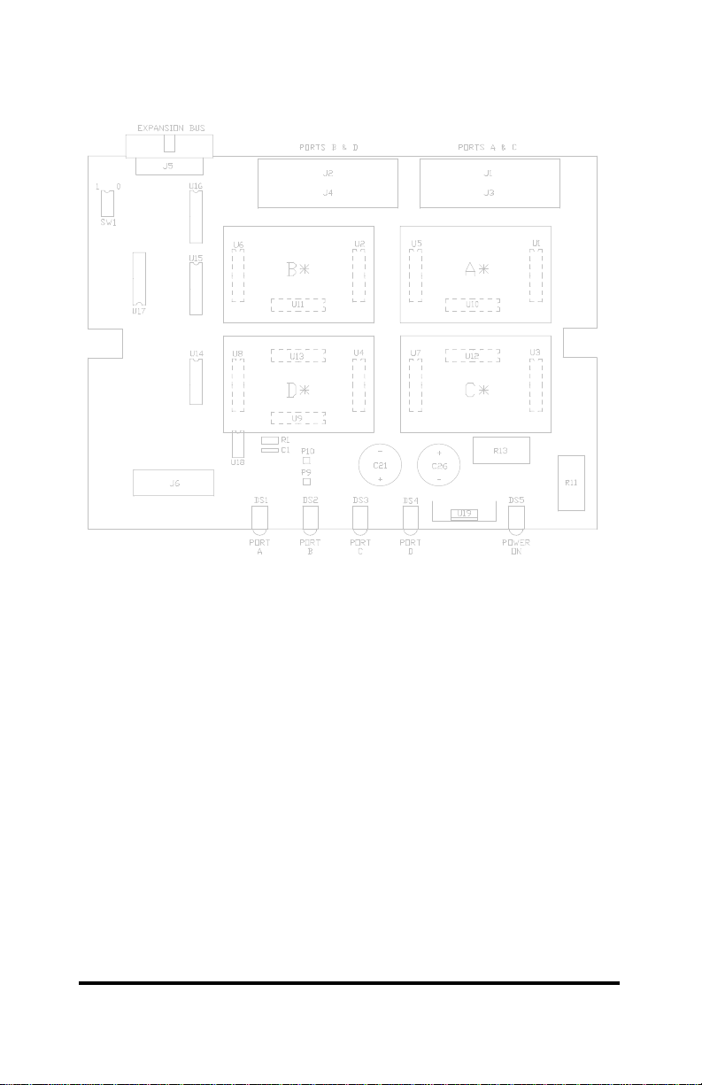
Figure 2. Printed Circuit Board Outline
* PC board for optional RS-422/485 port.
232PE3095 Manual 3
B&B Electronics -- PO Box 1040 -- Ottawa, IL 61350
PH (815) 433-5100 -- FAX (815) 434-7094
Page 8

Table 1. Address Switch
DIP Switch 1
1 2 3 4 Address
0 0 0 0 Invalid
1 0 0 0 1
0 1 0 0 2
1 1 0 0 3
0 0 1 0 4
1 0 1 0 5
0 1 1 0 6
1 1 1 0 7
0 0 0 1 8
1 0 0 1 9
0 1 0 1 10
1 1 0 1 11
0 0 1 1 12
1 0 1 1 13
0 1 1 1 14
1 1 1 1 15*
1 = OFF 0 = ON
* = FACTORY DEFAULT
Connecting To The Bus
Connecting the Port Expander to the Expandable Smart Switch
bus is a simple task. On the rear panel of the Port Expander is an
expansion bus cable, refer to Figure 3. This cable simply plugs into
the bus expansion connector located on the back of the last unit
connected to the Expandable Smart Switch bus.
Figure 3. Bus Connection Diagram
4 232PE3095 Manual
B&B Electronics -- PO Box 1040 -- Ottawa, IL 61350
PH (815) 433-5100 -- FAX (815) 434-7094
Page 9

Port Configuration
The 232PE has four selectable ports labeled "A" through "D".
Refer to Figure 8. Any of the ports can be manufactured to meet
either RS-232 or RS-422/485 electrical characteristics.
RS-232 Configuration
RS-232 ports will be wired as DTE ports. Refer to Table 2 for
pin out, signal name, and signal direction information. Also, refer to
Figure 4 for a simplified schematic showing the relationship
between the master port of the 232XSS and any RS-232 port of the
232PE. Refer to Appendix B for cable charts.
Table 2. RS-232 DTE PORTS A - D
RS-232 Signal
Direction of
DTE Ports A
Pin # Signal Description
TD Transmit Data Output
2
RD Receive Data Input
3
RTS Request to Send Output
4
CTS Clear to Send Input
5
DSR Data Set Ready Input
6*
SG Signal Ground <------>
7
CD Carrier Detect Input
8*
DTR Data Term Ready Output
20
* Pins 6 & 8 are tied together inside the 232PE and
share the same input, refer to Figure 4.
through D
232PE3095 Manual 5
B&B Electronics -- PO Box 1040 -- Ottawa, IL 61350
PH (815) 433-5100 -- FAX (815) 434-7094
Page 10

Figure 4. Simplified RS-232 Schematic
RS-422/485 Option
The RS-232 transmit and receive data signals on the master
port of the 232XSS will be converted to balanced full-duplex RS422 or half-duplex RS-485 signals with this option.
Table 3. RS-422/485 PORTS A - D
RS-422/485
Signal Direction
Pin # Signal Description
TD(A) Transmit Data (A) Output
2
TD(B) Transmit Data (B) Output
14
SG Signal Ground <------>
7
RD(A) Receive Data (A) Input
3
RD(B) Receive Data (B) Input
16
of Ports A - D
6 232PE3095 Manual
B&B Electronics -- PO Box 1040 -- Ottawa, IL 61350
PH (815) 433-5100 -- FAX (815) 434-7094
Page 11

Figure 5. Simplified RS-422/485 Schematic
When a port has this option, an additional printed circuit board
will be mounted to the main board. Use Figure 2 to locate its
position. Refer to Table 3 for pin out, signal name, and signal
direction information. Also, refer to Figure 5 for a simplified
schematic showing the relationship between the master port and a
port configured with the RS-422/485 option.
NOTE: This option only supports transmit and receive data signals
(TD & RD) from the master port.
Refer to Appendix B for cable charts.
RS-422 Mode
To configure the port for RS-422 four-wire mode, five jumpers
must be set. Jumper JP1 must be placed in the “SD” position.
Both JP2 jumpers must be placed in the four-wire “4W" position.
Jumper JP3 must be place in the "ON" position. Jumper JP4
should be placed in the "ON" position. Refer to Figure 6 for these
jumper locations.
232PE3095 Manual 7
B&B Electronics -- PO Box 1040 -- Ottawa, IL 61350
PH (815) 433-5100 -- FAX (815) 434-7094
Page 12

The EIA RS-422 Specification labels data lines with "A" and "B"
designators. Some RS-422 equipment uses a "+" and "-"
designator. In almost all cases, the "A" line is the equivalent of the
"-" line and the "B" line is the equivalent of the "+" line.
Figure 6. P.C. Board for Optional RS-422/485 Port
RS-485 Mode
There are two methods that can be used to control the RS422/485 driver: handshake control (RTS) and send data (SD)
control. These methods are jumper selectable (JP1 "SD" & "RTS").
Handshake control requires that the software use a handshake
signal to enable/disable the RS-485 driver. The handshake signal
RTS (pin 4) is used when the master port is configured as a DCE
port and CTS (pin 5) is used when the master port is configured as
a DTE port.
SD control automatically enables the RS-485 driver by sensing
the leading edge of the first character transmitted from the device
connected to the master port. After the last character is transmitted
the send data timer circuit waits one character time (1 millisecond
at 9600 baud) before disabling the RS-485 driver.
There are two components on the main printed circuit board, a
resistor (R1) and a capacitor (C1), that are part of the send data
control circuit. These components are factory selected for 9600
baud, which allows the send data control to operate at 9600 baud or
higher. With these two components the RS-485 driver will be
disabled approximately 1 millisecond after the last character has
8 232PE3095 Manual
B&B Electronics -- PO Box 1040 -- Ottawa, IL 61350
PH (815) 433-5100 -- FAX (815) 434-7094
Page 13

been sent. To change to a baud rate lower than 9600 baud, or to
configure the send data control to match a specific baud rate,
change R1 and C1 to the value specified in Table 4. Use Figure 2
to locate R1 and C1. Note that these timing components are not
used when the handshake control method is selected.
Table 4. Component Values For Send Data Timing
Baud Rate Time (ms)
Resistor Value
R1 (ohms)
Capacitor Value
C1(microfarads)
300 33.3 330K .1
600 16.6 160K .1
1200 8.33 820K .01
2400 4.16 430K .01
4800 2.08 200K .01
9600 1.04 100K .01
19.2K 0.520 56K .01
38.4K 0.260 27K .01
57.6K 0.176 16K .01
115.2K 0.0868 8.2K .01
The ECHO jumper (JP3) selects how the RS-485 receiver is
controlled. It can be set to ECHO ON which constantly enables the
receiver (RS-422, 4-wire mode) or to ECHO OFF which allows the
receiver to be automatically enabled when the RS-485 driver is
disabled (2-wire mode). When in the ECHO OFF position and in 2wire mode, the data being sent from the RS-232 device connected
to the master port will not be echoed back to the master port.
To configure a port for RS-485 two-wire mode, five jumpers
must be set. Jumper JP1 must be placed either the “SD” or the
“RTS” position, depending on how you control the RS-485 driver.
Both JP2 jumpers must be placed in the two-wire “2W” position.
Jumper JP3 must be place in the "OFF" position. Jumper JP4
should be placed in the "ON" position if this port is located at either
end of the multi-drop line, otherwise it should be in the "OFF"
position. Refer to Figure 6 for these jumper locations.
232PE3095 Manual 9
B&B Electronics -- PO Box 1040 -- Ottawa, IL 61350
PH (815) 433-5100 -- FAX (815) 434-7094
Page 14

Specifications
Model: 232PE
Size: 8"w x 6.3"d x 2.7"h
Power: 120Vac 60hz 16w
Figure 7. Front View
Figure 8. Rear View
10 232PE3095 Manual
B&B Electronics -- PO Box 1040 -- Ottawa, IL 61350
PH (815) 433-5100 -- FAX (815) 434-7094
Page 15

Appendix A: Cable Charts
232PE3095 Manual Appendix A A-1
B&B Electronics -- PO Box 1040 -- Ottawa, IL 61350
PH (815) 433-5100 -- FAX (815) 434-7094
Page 16

These charts indicate some common cable wiring based on the
DCE/DTE configuration of the 232XSS Master Port. Refer to the
Port Configuration section of the 232XSS manual for information on
Master Port configurations.
Chart 1. IBM PC DB25 Connector to Master Port
Master Port configured as a DCE port.
IBM PC
Serial Port
DB25 Connector
Signal
Direction
232XSS
Master Port (DCE)
DB25 Connector
2 -----------> 2
3 <----------- 3
4 -----------> 4
5 <----------- 5
6 <----------- 6*
7 <---------> 7
8 <----------- 8*
20 -----------> 20
* Pins 6 & 8 are tied together inside the 232XSS and share the
same output.
Chart 2. IBM PC DB9 Connector to Master Port
Master port configured as a DCE port.
IBM PC
Serial Port
DB9 Connector
Signal
Direction
232XSS
Master Port (DCE)
DB25 Connector
1 <----------- 8*
2 <----------- 3
3 -----------> 2
4 -----------> 20
5 <---------> 7
6 <----------- 6*
7 -----------> 4
8 <----------- 5
* Pins 6 & 8 are tied together inside the 232XSS and share the
same output.
A-2 Appendix A 232PE3095 Manual
B&B Electronics -- PO Box 1040 -- Ottawa, IL 61350
PH (815) 433-5100 -- FAX (815) 434-7094
Page 17

Chart 3. Modem DB25 Connector to Master Port
Master port configured as a DTE port.
Async Modem
Serial Port
DB25 Connector
Signal
Direction
232XSS
Master Port (DTE)
DB25 Connector
2 <----------- 2
3 -----------> 3
4 <----------- 4
5 -----------> 5
7 <---------> 7
8 -----------> 8*
20 <----------- 20
* Pins 6 & 8 are tied together inside the 232XSS and share the
same input.
NOTE: When using chart 3 above and connecting a DTE device
to ports A - H of the smart switch, refer to Charts 7 and 8.
Chart 4. DCE Device w/DB25 Connector to Ports A - D (DTE)
Master port of 232XSS configured as a DCE port.
DCE Device
Serial Port
DB25 Connector
Signal
Direction
232PE
Ports A - D (DTE)
DB25 Connector
2 <----------- 2
3 -----------> 3
4 <----------- 4
5 ----------> 5
6 ----------> 6*
7 <---------> 7
8 -----------> 8*
20 <----------- 20
* Pins 6 & 8 are tied together inside the 232PE and share the
same input.
232PE3095 Manual Appendix A A-3
B&B Electronics -- PO Box 1040 -- Ottawa, IL 61350
PH (815) 433-5100 -- FAX (815) 434-7094
Page 18

Chart 5. IBM PC DB25 Connector to Ports A - D (DTE)
Master port of 232XSS configured as a DCE port.
IBM PC
Serial Port
DB25 Connector
Signal
Direction
232PE
Ports A - D (DTE)
DB25 Connector
2 -----------> 3
3 <----------- 2
4 -----------> 5
5 <---------- 4
6 <---------- 6*
7 <---------> 7
8 <----------- 8*
20 -----------> 20
* Pins are tied together inside the 232PE and share the same
input.
Chart 6. IBM PC DB9 Connector to Ports A - D (DTE)
Master port of 232XSS configured as a DCE port.
IBM PC
Serial Port
DB9 Connector
Signal
Direction
232PE
Ports A - D (DTE)
DB25 Connector
2 <----------- 2
3 -----------> 3
4 -----------> 6*
5 <---------> 7
6 <----------- 20
7 -----------> 5
8 <----------- 4
* Pins 6 & 8 are tied together inside the 232PE and share the
same input.
A-4 Appendix A 232PE3095 Manual
B&B Electronics -- PO Box 1040 -- Ottawa, IL 61350
PH (815) 433-5100 -- FAX (815) 434-7094
Page 19

Chart 7. IBM PC DB25 Connector to Ports A - D (DTE)
Master port of 232XSS configured as a DTE port with a
modem connected (see Chart 3).
IBM PC
Serial Port
DB25 Connector
Signal
Direction
232PE
Ports A - D (DTE)
DB25 Connector
2 -----------> 3
3 <----------- 2
4 -----------> 5
5 <----------- 4
6 <---- ----> 6*
7 <---------> 7
8 <----------- 20
20 -----------> 6*
* Pins 6 & 8 are tied together inside the 232PE and share the
same input.
Chart 8. IBM PC DB9 Connector to Ports A - D(DTE)
Master port of 232XSS configured as a DTE port with a modem
connected (see Chart 3).
IBM PC
Serial Port
DB9 Connector
Signal
Direction
232PE
Ports A - D (DTE)
DB25 Connector
3 -----------> 3
2 <----------- 2
7 -----------> 5
8 <----------- 4
6 <---- ----> 6*
5 <---------> 7
1 <----------- 20
4 -----------> 6*
* Pins 6 & 8 are tied together inside the 232PE and share the
same input.
232PE3095 Manual Appendix A A-5
B&B Electronics -- PO Box 1040 -- Ottawa, IL 61350
PH (815) 433-5100 -- FAX (815) 434-7094
Page 20

Chart 9. RS-422/485 4-Wire Device to Port (A - D) Configured
as an RS-422 /485 Port.
Master port of 232XSS configured as an RS-232 DCE port.
RS-422/485
4-Wire
Device
Signal
Direction
232PE
Ports A - D
DB25 Connector
TD (A)* -----------> 3 - RD (A)
TD (B)* -----------> 16 - RD (B)
Signal Ground <----------> 7 - SG
RD (A)* <----------- 2 - TD (A)
RD (B)* <----------- 14 - TD (B)
* If the device being connected uses "+" and "-" in place of "B"
and "A", the "+" replaces the "B" and the "-" replaces the "A".
NOTE: Make sure the port's set up jumpers are in the proper
position for four-wire communications.
Chart 10. RS-422/485 2-Wire Device to Port (A - D) Configured
as an RS-422/485 Port.
Master port of 232XSS configured as an RS-232 DCE port.
RS-422/485
2-Wire
Device
Signal
Direction
232PE
Ports A - D
DB25 Connector
Data (A)* <----------> 2 - TD (A)
Data (B)* <----------> 14 -TD (B)
Signal Ground <----------> 7 - SG
* If the device being connected uses "+" and "-" in place of "B"
and "A", the "+" replaces the "B" and the "-" replaces the "A".
NOTE: Make sure the port's set up jumpers are in the proper
position for two-wire communications.
A-6 Appendix A 232PE3095 Manual
B&B Electronics -- PO Box 1040 -- Ottawa, IL 61350
PH (815) 433-5100 -- FAX (815) 434-7094
Page 21

FEDERAL COMMUNICATIONS COMMISSION
RADIO FREQUENCY INTERFACE STATEMENT
Class A Equipment
This equipment has been tested and found to comply with the
limits for Class A digital device, pursuant to Part 15 of the FCC
Rules. These limits are designed to provide reasonable protection
against harmful interference when the equipment is operated in a
commercial environment. This equipment generates, uses, and can
radiate radio frequency energy and, if not installed and used in
accordance with the instructions, may cause harmful interference to
radio communications. Operation of this equipment in a residential
area is likely to cause harmful interference, in which case the user
will be required to correct the interference at personal expense.
FCC Class A Equipment Statement
 Loading...