

Page 1
© 2002 by B&B Electronics. All rights reserved.
www.bb-elec.com orders@bb-elec.com support@bb-elec.com
International Office: 707 Dayton Road PO Box 1040 Ottawa, IL 61350 USA 815-433-5100 Fax 433-5104
European Office: Westlink Commercial Park Oranmore Co. Galway Ireland +353 91 792444 Fax +353 91 792445
PRODUCT INFORMATION B&B ELECTRONICS
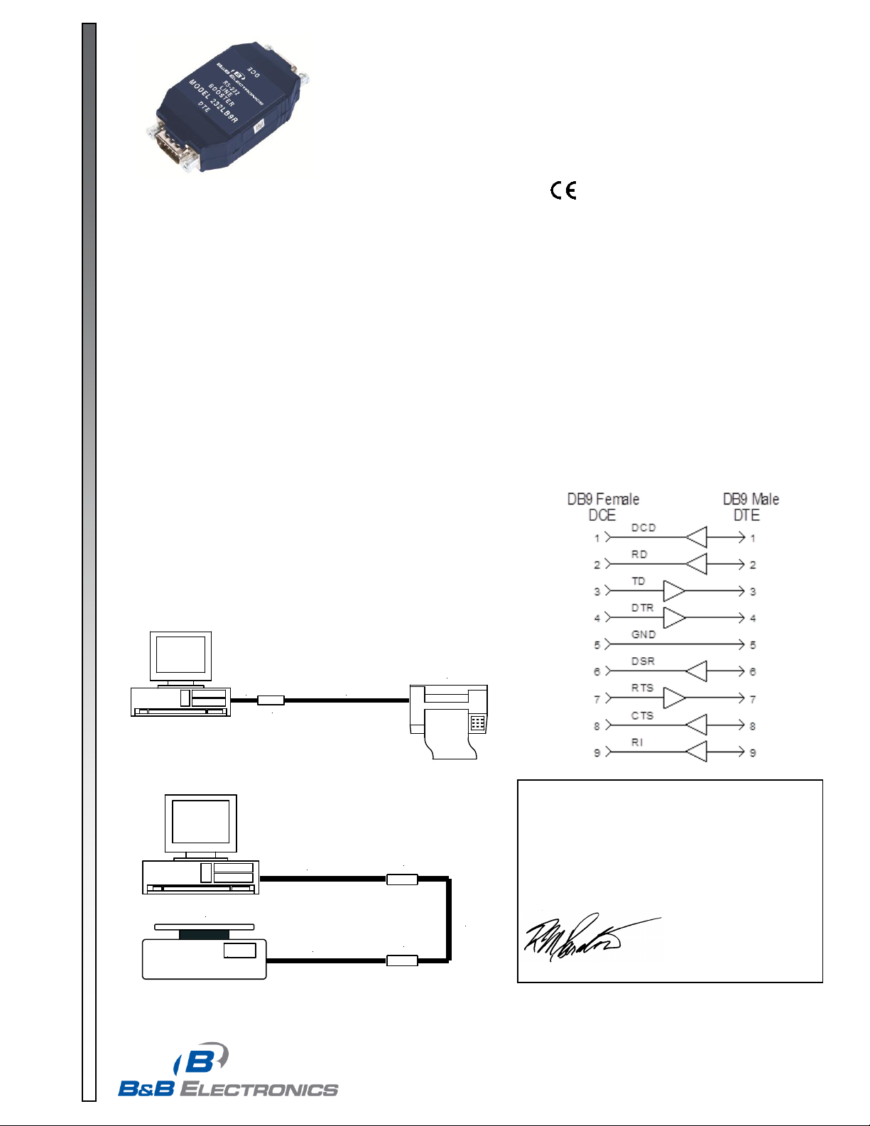
Figure 1: Signal Direction
Figure 2: Boosting Low Power Ports
232LB9R
Short
Printer
50 ft
Figure 3: Lengthening Cable Runs
78.6
232LB9R
Scale
232LB9R
50 ft
50 ft
50 ft
DECLARATION OF CONFORMITY
Manufacturer’s Name: B&B Electronics Manufacturing Company
Manufacturer’s Address: P.O. Box 1040
707 Dayton Road
Ottawa, IL 61350 USA
Model Number: 232LB9R
Description: 9-pin RS-232 Line Booster
Type: Light industrial ITE equipment
Application of Council Directive: 89/336/EEC
Standards: EN 50082-1
EN 61000 (-4-2, -4-3, -4-4, -4-6)
Robert M. Paratore, Director of Engineering
232LB9R0812-1/1
Model: 232LB9R
9-Pin RS-232 Line Booster
Overview
The 232LB9R is a 9-pin RS-232 repeater that re-transmits all 8 signals and carries the ground line through.
Many CE computers, laptops, and some desktops ship with low-power versions of RS-232 ports that are unable to drive
port-powered devices or full-length RS-232 cabling. The 232LB9R can amplify these weak signals up to the RS-232
Standard for uses such as running port powered devices. It is also ideal for extending full-powered RS-232 cable runs
beyond the typical 50 to 100 feet.
Installation
To amplify low-power ports using the 232LB9R, the converter is installed close to the low-powered port as
shown in Figure 2, and the other device is installed within the typical full-powered RS-232 length. To use as a line
booster for extending an RS-232 cable run, the 232LB9R should be installed no more than 50 feet from any RS-232
transceiver in the system. For very long cable runs, two or more line boosters may be required for proper operation of
the RS-232 interface as shown in Figure 2.
The 232LB9R must be installed so that the signals flow in the proper direction. Figure 1 shows the direction of
flow on each line. The female connector end is pinned out as DCE and connects directly to a standard COM port on a
computer or any other DTE interface. The male connector is pinned out as DTE and connects to any DCE device such
as a modem or another 232LB9R.
Specifications
Dimensions: 3.1 x 1.7 x 0.8 in (7.9 x 4.3 x 2.1 cm)
Temperature Range: 0 to 70°C
Supply Voltage: +12 to 16 VDC@ 40 mA max
Data Rates: Up to 115.2 kbps
Connectors: DB9 female for DCE side
DB9 male for DTE side
 Loading...