


482
SONIC MAXIMIZER
User Guide
and
Reference
Manual

i
TABLE OF CONTENTS
Important Safeguards ……………………………………………………………………………………………………………i
BBE Process Explained …………………………………………………………………………………………………………1-2 Product Description ………………………………………………………………………………………………………………2
Applications ………………………………………………………………………………………………………………………2
Controls and Connections ………………………………………………………………………………………………………3
Specifications ………………………………………………………………………………………………………………………4
General Operation ………………………………………………………………………………………………………………4
Application Diagrams …………………………………………………………………………………………………………5-9 Service /Warranty / Maintenance ……………………………………………………………………………………………10
Calibration Procedures …………………………………………………………………………………………………………11
Schematic Diagrams…………………………………………………………………………………………………………12-15
Congratulations on your purchase of the BBE 482 Sonic Maximizer—a two channel signal processor that will benefit any recording or sound reproduction system. You now own a very unique signal processing device with no equal in the audio world. Whether you purchased the BBE 482 for your home studio, P.A., DJ system, or instrument rack, you will find the 482's rugged construction and careful electronic design a welcome addition to your sonic arsenal.
Thank you for your purchase, and for the trust that you've placed in BBE. We are committed to bringing you the finest products, with useful and unique features to serve your audio needs.
The BBE Process—"What it Is"
Loudspeakers have difficulty working with the electronic signals supplied by an amplifier. These difficulties cause such major phase and amplitude distortion that the sound reproduced by speaker differs significantly from the sound produced by the original source.
In the past, these problems proved unsolvable and were thus delegated to a position of secondary importance in audio system design. However, phase and amplitude integrity is essential to accurate sound reproduction. Research shows that the information which the listener translates into the recognizable characteristics of a live performance are intimately tied into complex time and amplitude relationships between the fundamental and harmonic components of a given musical note or sound. These relationships define a sound's “sound”.
When these complex relationships pass through a speaker, the proper order is lost. The higher frequencies are delayed. A lower frequency may reach the listener's ear first or perhaps simultaneously with that of a higher frequency. In some cases, the fundamental components may be so time-shifted that they reach the listener's ear ahead of some or all of the harmonic components.
This change in the phase and amplitude relationship on the harmonic and fundamental frequencies is technically called “envelope distortion.” The listener perceives this loss of sound integrity in the reproduced sound as "muddy" and “smeared.” In the extreme, it can become difficult to tell the difference between musical instruments, for example, an oboe and a clarinet.
BBE Sound, Inc. conducted extensive studies of numerous speaker systems over a ten year period. With this knowledge, it became possible to identify the characteristics of an ideal speaker and to distill the corrections necessary to return the fundamental and harmonic frequency structures to their correct order. While there are differences among various speaker designs in the magnitude of their correction, the overall pattern of correction needed is remarkably consistent.
The BBE Process is so unique that 42 patents have been awarded by the U.S. Patent Office.
1

Product Description
The BBE 482 is a dual channel, single rack space device for use in -l0dBu line level applications. For each channel there are one pair of Lo Contour and Process knobs plus a 5 segment LED input level meter. A single function button switches the BBE process on or off in both channels, which is useful for comparing the processed sound to the unprocessed sound. An LED next to the function button glows green when the BBE process is on and red when the process is off. The Lo Contour controls are for adjusting the level of phase corrected low frequencies in the program material. The Process controls are for adjusting the level of phase corrected high frequencies in the program material.
Things to Remember
The BBE 482 is designed to work with -l0dBu line levels. This is suitable for professional and semi-pro mixers, P.A. consoles, recording studios, or D.J. equipment. The BBE 482 drives load impedances down to 1K Ohm and supplies a maximum output level of +18dBu. Plugging a guitar or other high impedance device directly into the BBE 482 will not work properly as its input impedance is less than 50K ohms.
Set-Up
The BBE 482 is connected into the chain in series with the signal path the same way a graphic equalizer or limiter would be connected. The output of a mixer, pre-amp, or other sound source feeds the input of the BBE 482. Setting up the BBE 482 as an echo send device like a digital reverb is not recommended as the processed effect is not fully realized when summed with the original source audio.
WARNING! To prevent possible speaker or amplifier damage, always power-up peripheral devices first, wait 10 seconds, and then turn on the power amplifier. Turn off power amplifier first, then power-down peripheral devices.
APPLICATIONS
Music and P.A. Systems
The BBE 482 is a welcome addition to any live sound P.A. system because the BBE circuit dramatically improves the clarity and intelligibility of vocals and musical instruments. Night club and mobile DJ systems will also benefit greatly from the BBE Process, with more depth, detail and punch over the entire mix. The 482 can be hooked up to any P.A. or DJ sound system exactly like an equalizer would. When using in conjunction with an equalizer, the 482 should be added after the equalizer in the signal chain. In the event that the equalizer is being used for drastic tone alteration, then insert the 482 before the equalizer in the signal chain. Placement either before or after an equalizer should have no negative effect on the 482 unit or its processing ability, however most users find they prefer more modest use of their equalizers once the BBE 482 has been added to their sound systems.
Instrument Racks
The BBE 482 will deliver surprisingly good results in guitar, bass and keyboard rack systems. Electric guitars have added “bite”, “chunk” and improved definition. As Guitar Player magazine said, “BBE is the most cost effective improvement you can add to your rig”. Acoustic guitars processed with the 482 have a breathtakingly natural sparkle and presence. Bassists will delight in the BBE 482's ability to bring much more punch to the bottom end without muddying up the midrange. The 482 is also great for keyboard rigs, with everything from the latest samples to a vintage Rhodes benefiting equally from the patented BBE process.
Recording Systems
The BBE 482 can be used as an effect on individual tracks or applied overall during mixdown. The BBE process works very well to liven up the final mix, which is why the BBE 482 and 882 models are popular for use in both recreational and professional recording studios.
2
|
|
|
|
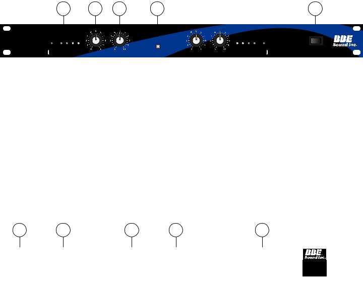
FRONT PANEL CONTROLS |
1 |
2 |
3 |
4 |
5 |
|
|
|
|
POWER |
482 |
|
|
|
|
|
B B E P R O C E S S |
|
|
|
|
|
|
SONIC MAXIMIZER |
CLIP |
0 |
- 6 |
- 12 |
- 20 |
IN |
OUT |
- 20 |
- 12 |
- 6 |
0 |
CLIP |
|
|
|
|
|
|
|
|
|
|
|
|
ON |
C H A N N E L A |
LO CONTOUR |
PROCESS |
FUNCTION |
LO CONTOUR |
PROCESS |
C H A N N E L B |
▼▼
®
OFF
1.LED DISPLAY: The LED display is used to indicate the output signal level of the BBE 482. Each number on the front panel corresponds to the output signal level, measured in decibels. Example: The “0” indicates a 0dBu signal level, “-6” refers to -6dBu, and so on. Once an input signal level has been established, increasing the BBE PROCESS and LO CONTOUR will increase the output signal and cause more LEDs to illuminate. The Clip LED monitors the input signal level. The Clip LED will illuminate at +15dBu, giving a 3dBu warning of the impending distortion at +18dBu, the actual clip point.
2.LO CONTOUR: Regulates the amount of phase corrected bass frequencies.
3.PROCESS: Regulates the amount of phase corrected treble frequencies.
4.BBE FUNCTION: This push button switch allows for quick comparison of processed with unprocessed sound. When the switch is pushed in, the process is on and the indicator LED is green. When the switch is out, the process is off and the indicator LED is red.
5.POWER: This switch controls primary power to the BBE 482.
REAR PANEL CONNECTIONS
1 |
2 |
3 |
4 |
5 |
CALIFORNIA USA
MODEL 482
US PATENT
NO 4,482,866
AND OTHERS
1.AC POWER CORD: Plugs into AC power receptacle. U.S. Model, 100-120Vac, 50/60Hz. All other models,220~240Vac, 50/60Hz.
2.FUSE: Turn cap on fuse holder counter-clockwise to remove fuse. (Note: For U.S. Model, replace with 250Vac, 1/2A Fastblow type fuse. For all other models, replace with 250Vac, .125A Fastblow type fuse.)
3.OUTPUT: The output of the BBE 482 can be taken from the 1/4” Phone Jack or the RCA Jack. Both are unbalanced and are the same point electronically. This allows both outputs to be used simultaneously, eliminating the need for a “Y” cord in the event multiple outputs are required. The recommended single load impedance is at least 10k Ohms. If both outputs are being used, a minimum of a 22k Ohm load per device is required. (The “load” is determined by the input impedance of the next subsequent component in the signal chain.) The maximum output is rated at +18dBu. The output impedance of the BBE 482 is 1 k ohms. NOTE: Actual output level will vary due to the selected position of the BBE Process, and the actual input signal level.
4.INPUT: The input of the BBE 482 is an unbalanced connection. Although is can be either a 1/4” Phone Plug or an RCA Plug, it is recommended that only one input source is used. Both jacks are the same point electronically, however, due to the input/output impedance characteristics of most audio devices, a loss of signal may occur and/or damage to a component if both inputs are utilized. The input impedance of th BBE 482 is 47k Ohms. The maximum signal level is +18dBu.
5.CHANNEL A: These connections function the same as CHANNEL B.
3
Specifications
Frequency Response,
process mode:……………………………Program controlled
bypass mode: ……………………………10Hz to 50kHz +/-0.5dBu, -10dBu input
THD, process mode:……………………………less than 0.025% at -10dBu input, 20-20kHz bypass mode: ……………………………less than 0.002% at -l0dBu input, 20-20kHz
Maximum Output: ………………………………+18dBu (may vary due to control settings)
Input Impedance: ………………………………47k Ohms, unbalanced 1/4" phone jack or RCA jack Output Impedance: ……………………………1 k Ohms, unbalanced 1/4" phone jack or RCA jack Sensitivity: …………………………………………-45dBu for maximum process
Maximum Process: ………………………………+12dBu boost at 5kHz, -l0dBu input Lo Contour: ………………………………………+12dBu boost at 50Hz, -l0dBu input
* 0dBu = 0.775mVrms
Power Requirements: ……………………………U.S., Canada 8 Japan models: 120VAC, 50/60Hz, 8 WATTS Standard model: 220VAC, 50/60Hz, 8 WATTS
Fuse: ………………………………………………Replace with the same type FASTBLOW fuse
U.S., Canada & Japan models: 250Vac, 1 /2A Fast blow type fuse. Standard model: 250Vac, .125A Fastblow type fuse
Dimensions: …………………………………...... 19"(W) x 5.5"(D) x 1.7"(H) Shipping Weight: ………………………………6.5 lbs.
Note: Due to continuing product improvement, specifications and design are subject to change without notice.
General Operation
THE BBE 482 IS A LINE LEVEL SIGNAL PROCESSOR AND IS TO BE CONNECTED PRIOR TO THE POWER AMP IN ANY AUDIO SYSTEM. SIGNIFICANT DAMAGE MAY BE INFLICTED TO THE BBE 482 OR ANY SUBSEQUENT COMPONENT IN THE SYSTEM IN THE EVENT THE OUTPUT OF A POWER AMP IS CONNECTED DIRECTLY TO THE INPUT OF THE BBE 482.
In order to reduce the risk of damage to any equipment, properly connect all cables and power cables before turning on any components in the system. Most important of all, ALWAYS TURN ON THE POWER AMPLIFIER
LAST TO AVOID DAMAGING THE SPEAKERS OR THE AMP.
The BBE 482 may be utilized in a number of different environments and its results may vary accordingly. Because both channels are completely independent from each other, only one channel of the BBE 482 may be used, or each channel processing a different signal source. The effects loop is the ideal placement in the signal chain of a guitar application. In a pre-amp, keyboard or P.A. application, the BBE 482 works best as the last component in the signal chain, just before the crossover or power amp. Important: In a P.A. application, never connect the BBE 482 into the effects loop. The inherent phase shift of the BBE Process will cause phase cancellation resulting in a partial loss of signal.
BBE and Equalization
The most common question asked of the BBE Sound, Inc. service department is: “Where does the BBE Processor connect in the signal chain, before or after the equalizer?” Many people find that the same amount of equalization is no longer needed, if at all, when a BBE processor is used. Additionally, the amount of equalization used will help determine the BBE 482’s proper location in the signal chain: If the EQ is being set to give the room a flat response as determined by a spectrum analyzer, the BBE 482 will work properly before or after the EQ. (Placing the BBE 482 after the EQ is recommended.) If the EQ is being used for drastic tone alteration, the recommended placement would be before the EQ. Neither of these configurations will harm the BBE 482.
4
 Loading...