

Page 1

362dzu
User Guide
di^ii
Reference
Manual
4- SUB WUO№M
i i
Sonic Maximizer + Sub-woofer Filter
um
Sound, Inc.
Page 2

Important Safeguards
WARNING
CAUTION
RISK OF ELECTRIC SHOCK
DO NOT OPEN
CAUTION: TO REDUCE THE RISK OF ELECTRIC SHOCK,
DO NOT REMOVE COVER (OR BACK).
NO USER-SERVICEABLE PARTS INSIDE.
REFER SERVICING TO QUALIFIED SERVICE PERSONNEL.
A
To prevent fire or shock hazard, do not expose
the unit to rain or moisture.
ATTENTiON: RISQUE DE CHOC
The lightning flash with arrowhead symbol, within
an equilateral triangle, is intended to aiert the user
to the presence of uninsulated "dangerous
voltage" within the product’s enclosure that may
be of sufficient magnitude to constitute a risk of
electric shock to persons.
The exclamation point, within a equilaterai triangie
is intended to alert the user to the presence of
important operating and maintenance (servicing)
instructions in the iiterature accompanying the
appliance.
ELECTRIC- NE PAS
OUVRIR.
For your protection, please read these safety instructions completely before operating the appliance, and keep this manual for future reference.
Carefully observe all warnings, precautions and instructions on the appliance and described in the
operating instructions supplied with the appliance.
INSTALLATION---------------------------------------------------------------------------------------------------------------------------------------------
Water and Moisture - Do not install the
appliance near water: for example, near a
bathtub, washbowl, kitchen sink, laundry tub,
in a wet basement, or near a swimming pooi.
Heat - Do not instaii the appliance near
sources of heat such as radiators, heat regis
ters, stoves, or other appliances that pro
duce heat.
Ventilation - Situate the product so its
location or position does not interfere with its
proper ventilation. For example, you should
not place the product on a bed, sofa, rug, or
similar surface that might block the vent
openings, or placed in a built-in installation,
such as a bookcase or cabinet that might
impede the flow of air through the ventilation
openings.
Wall or Ceiling Mounting - If your
appliance can be mounted to a wall or ceil
ing, mount it only as recommended.
USE
Power Source - Connect the appliance
to a power supply only of the type described
in the operating instructions or as marked on
the appliance.
Power-Cord Protection - Route the
power cord so that it is not likely to be walked
on or pinched by having objects placed on it,
paying particular attention to the plugs,
receptacles, and the point where the cord
exits from the appliance.
SERVICE
Unplug the appliance from the wall outlet and
consult qualified service personnel when:
• the power cord or the plug has been
damaged.
* a solid object or liquid has fallen into the
cabinet.
Grounding or Poiarization - Do not
defeat the grounding or polarization feature of
the AC power cord. If your AC receptacle will
not accept the power cord plug, contact your
electrician to install a proper AC receptacle.
When not in use - unplug the power
cord of the appliance from the outlet when left
unused for a long period of time.
To disconnect the cord, pull it out by grasping
the plug. Never pull the plug out by the cord.
■ the appliance has been exposed to rain or
moisture.
‘ the appliance does not appear to operate
normally or exhibits a marked change in
performance.
> the appliance has been dropped, or thé
enclosure damaged.
AC Receptacie - Check to make sure
that the AC receptacle holds the power cord
plug firmly and securely. If the power cord
plug is loose, contact your electrician to
replace the defective and unsafe AC
Foreign Objects - Be careful that foreign
objects and liquids do not enter the enclosure
through openings.
Do not attempt to service the appliance
beyond that described in the operating
instructions. For all other sen/icing, refer to
qualified sen/ice personnel only.
Page 3

Welcome
Congratulations on your purchase of the BBE 362SW Sonic Maximizer + Sub-woofer Filter - a
two channel signal processor that will benefit any sound reproduction system. You now own a
very unique signal processing tool with no equal in the audio world. We're confident that with
your purchase of the BBE 362SW, you will find its rugged construction and careful electronic
design a welcome addition to your sonic arsenal.
This book is divided into two main parts: the User Guide and the Reference Manual. The User
Guide will help you to effectively use the BBE process and sub-woofer filter. In this section you'll
find complete instructions regarding the controls and connections, along with some application
notes and diagrams. In the Reference Manual, we've included specifications, a calibration proce
dure, and all of the related technical information regarding Service, Warranty and Maintenance for
your product.
Thank you for your purchase, and for the trust that you've placed in BBE. We are committed
to bringing you the finest products, with useful and unique features, to solve your audio needs. If
you have any comments or questions about this product that are not answered in this book,
please feel free to call us at (714) 897-6766 - we're always glad to be of service.
User Guide Contents
Important Message
Welcome..................................
The BBE Process Explained
Product Description...............
Controls and Connections
Application Notes / Diagrams..
................
....
,. inside cover
..................
..................
.
..................
...............
...............
Reference Manual Contents
1 Specifications
2 Warranty
3
4-5
6-8 Schematic Diagrams
Maintenance & Service
Calibration Procedures
........................
.................................
.........
........
.............
e
..................
................
................
...........
...........
12-13
14-17
9
10
11
Page 4

The BBE Process Explained
What is BBE? (some big words to describe the mysteries of our little black box)
Loudspeakers have difficulty dealing with the electronic signals supplied by an amplifier. These
difficulties cause such major phase and amplitude distortion that the sound reproduced by a
speaker differs significantly from the sound produced by the original source.
In the past, these problems proved unsolvable and were thus delegated to a position of
secondary importance in audio system design. However, phase and amplitude integrity is essen
tial to accurate sound reproduction. Research shows that the information which the listener
translates into the recognizable characteristics of a live performance are intimately tied into com
plex time and amplitude relationships. These relationships define a sound's "sound".
When these complex relationships pass through a speaker, the proper order is lost. The
listener perceives this loss of sound integrity in the reproduced sound as "muddy" and "smeared".
BBE Sound, Inc. conducted extensive studies of numerous speaker systems over a ten year
period. With this knowledge, it became possible to identify the characteristics of an ideal speaker
and to distill the corrections necessary to return the fundamental and harmonic frequency struc
tures to their correct order. While there are differences among various speaker designs in the
magnitude of their correction, the overall pattern of correction needed is remarkably consistent.
The BBE process is so unique that 42 patents have been awarded by the U.S. Patent Office.
How does BBE work? (a mildly technical expose - for those that need to know)
The BBE Process imparts a predetermined phase correction to the high frequencies where
most harmonic information exists. This is done by breaking the signal into three sub-bands or
groups:
a. ) LOWS (20Hz-150Hz)
b. )MIDs 050Hz-1200Hz)
c. ) HIGHs (1200Hz-20kHz).
The low group is delayed about 2.5 ms (milliseconds) via a delay within the passive low pass
filter. The front panel LO CONTOUR control allows for either a flat response or a boost at 50Hz.
The mid-range group is delayed only about 0.5ms and passes through an active band-pass filter
while the high frequency group is passed through a VGA (Voltage Controlled Amplifier). The high
group is used as a point of reference to make dynamic amplitude corrections to the high frequen
cies.
The RMS average loudness detectors continuously monitor both the mid-range and high fre
quencies to compare the relative harmonic content levels of the two bands and apply the appro
priate amount of control voltage to the VGA, thereby determining the amount of high frequency
harmonic content present at the final output of the BBE processor.
Page 5

Product Description
The BBE 362SW is an intelligent audio processor and a sub-woofer filter network combined
into one unit. The true beauty of the BBE 362SW is in its ease of set-up and operation. The BBE
362SW is a ganged dual channel, single rack space device for use in -lOdBu unbalanced line level
applications.
The BBE portions of the BBE 362SW consist of a Function switch, Lo Contour control. Process
control and a pair of clip lights. The Function switch is for comparing the processed sound to the
direct sound. The Lo Contour control is for adjusting the level of phase corrected low frequencies
in the program material. The Process control is for adjusting the level of the phase corrected high
frequencies in the program material. Each channel output is monitored by a clipping circuit
which turns on a LED when the output level is at 3dB below true clipping.
The Sub-woofer Filter portion of the BBE 362SW consists of a Sub-woofer Frequency control
and a Sub-woofer Level control. The phase corrected low frequency information from both chan
nels is summed together and directed through an 18dB/octave filter network. The Sub-woofer
Frequency control adjusts this filter, and has a selectable range from 30hz to 120hz. By simply
adjusting the Frequency control you can set the filter's frequency point of the Sub-woofer circuit.
For example, if you set the Frequency control to 40hz - then only the information below 40hz will
be sent to the Sub-woofer Output jack. The Sub-woofer Level control adjusts the output level of
the sub-woofer circuit. The level is adjustable from fully off to a gain of 6dB.
Page 6
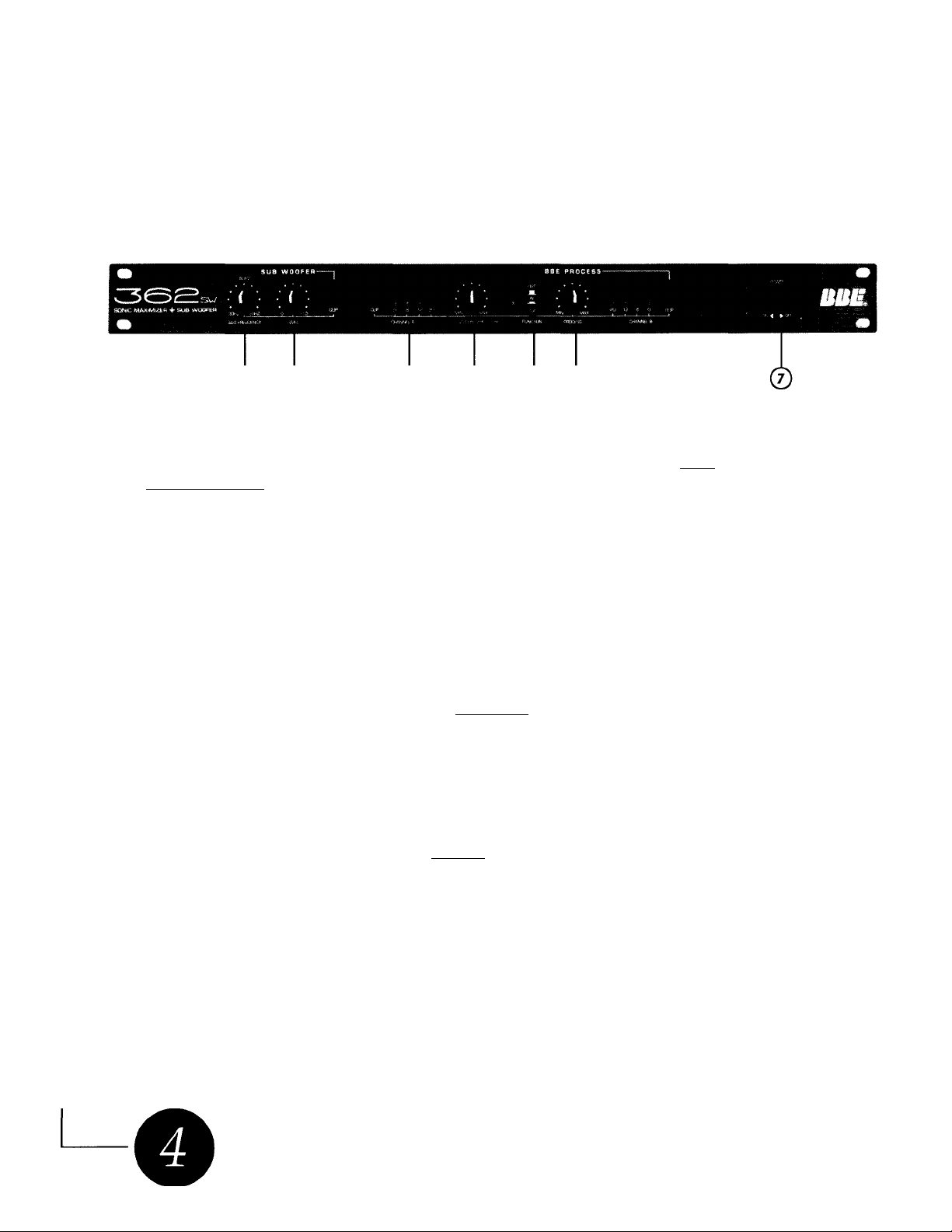
Front Panel Controls
(D ©
7. SUB-WOOFER FREQUENCY: The phase corrected low frequency information from both chan
nels is summed together and directed through an 18dB/octave filter network. The Sub
woofer Frequency control adjusts this filter, and has a selectable range from 30hz to 120hz.
By simply adjusting the Frequency control you can set the filter's frequency point of the
Sub-woofer circuit. For example, if you set the Frequency control to 40hz - then only the
information below 40hz will be sent to the Sub-woofer Output jack.
2. SUB-WOOFER LEVEL: This control adjusts the output level of the sub-woofer circuit. The level
is adjustable from fully off to a gain of 6dB.
3. CLIP LEDs: These LEDs indicate when the output of the BBE 362SW is 3dB below true
clipping.
4. LO CONTOUR: Each channel shares a common Lo Contour control that regulates the amount
of phase corrected bass frequencies.
5. BBE FUNCTION: This push button switch allows for quick comparison of the processed and
unprocessed sound. When the switch is pushed in, the process is on and the indicator LED
is green. When the switch is out, the process is off and the indicator LED is red.
© © © ©
6. PROCESS: Each channel shares a common Process control that regulates the amount of
phase corrected treble frequencies.
7 POWER: This switch controls the primary power to the BBE 362SW.
Page 7

Rear Panel Connections
A I CAUTIOWn A
®
8. AC POWER CORD: Plugs into AC power receptacle. U.S. Model, 100-120Vac, 50/60Hz. All
other models, 200-240Vac, 50/60Hz.
9. FUSE: Turn cap on fuse holder counterclockwise to remove fuse. (Note: For U.S. Model,
replace with 250Vac, 1/2A Fastblow type fuse. For all other models, replace with 250Vac,
. 125A Fastblow type fuse.)
JO. UNBALANCED FULL RANGE OUTPUTS: Each channel is equipped with a 1/4" phone jack and
an RCA jack - each sends a low impedance line level output, and can deliver up to a
-I-16dBu into 1K Ohms.
^ U.i
lUiE
CAUraRNIA. U S A
tMOOEL 362 6W
U S.PATEIVrr
//. UNBALANCED INPUTS: Each channel is equipped with a 1/4" phone jack and an RCA jack
that accepts a high impedance unbalanced line level input with an average of -lOdBu.
(Note; -)-16dBu is the maximum input before clipping.)
12. UNBALANCED SUB-WOOFER OUTPUTS: The Sub-woofer output is equipped with a 1/4"
phone jack and an RCA jack - each sends a low impedance line level output.
Page 8

Application Notes
Benefits of a Sub-Woofer System
First, let's define sub-woofer: a sub-woofer is a specially designed speaker system that repro
duces ultra-low frequencies only. You may have heard these systems called "subs", or a "sub bin"
- but why are they important? In a standard "full-range" speaker enclosure, the components
inside are required to reproduce the entire range of sound, from bass to midrange to highs, all in
the same "box". In large applications, and in high-power applications, the resulting sound can be
muddy, garbled and lacking punch. With a sub-woofer system, the sound is routed through a
filter (like the BBE 362sw) where the sound is divided into two "bands". The mids and highs go
to the main power amp and then to the regular "full-range" speaker cabinets, while the lows
(bass) are sent to a separate power amp and then to the specially designed "sub-woofer" speaker
cabinets. The resulting sound is more defined, punchier, and capable of remaining loud and clear
in most any application. You'll find the BBE 362SW the perfect solution for maximizing your sonic
needs (!) as well as controlling that all important sub-woofer punch.
Things to Remember
The BBE 362SW is designed to work with -lOdBu levels. This is suitable for most semi-pro mixers,
P.A. consoles, home recording systems, or D.J. equipment. The BBE 362SW drives load imped
ances down to IK Ohm and supplies a maximum output level of -i-16dBu. Plugging a guitar or
other high impedance device into the BBE 362SW will not work properly as its input impedance
is 50K Ohms.
Set-Up
The BBE 362SW is connected into the chain in series with the signal path the same way a graphic
EQ or limiter would be connected. The output of a mixer, pre-amp, or other sound source feeds
the input of the BBE 362SW. Setting up the BBE 362SW as an aux. send device like a reverb is not
recommended as the processed effect is not fully realized when summed in parallel with the
original audio source.
WARNING!
To prevent possible speaker or amplifier damage, always power-up peripheral devices first, wait
10 seconds, and then turn on the power amplifier. Turn off power amplifier first, then power
down peripheral devices.
Page 9

Application Diagram (A)
c
Full-range Mix
Power Amp
Sub-woofer
Power Amp
c
o
Page 10

Application Diagram (B)
DJ. Mixing
Console
Outputs
CAUTION
ATTENTION.
100'120VAC
A
WARNING' CHANNELS
AVIS
aîühSJa ^ ^
Full-range Mix
Power Amp
OUTPUT
r
c_o
©
CHANNEL A
OUTPUT
^ Cj.
CHANNEL B
INPUT
^ kl
CHANNEL A
' c
sus WOOFEB
- ^ CAUFOWMlfl, USA
< g WOOELIE2SVK
: luu-
%. IW -1.483 esG
^ ANO OrHtBS
O
Page 11

BBE 362sw
Sonic Maximizer + Sub-ivoofer filter
Reference Section
BBE 362SW Specifications
Frequency Response
Bypass..................................................5hz to 30kHz
Process........................................program controlled
Signal to Noise Ratio
Total Harmonic Distortion
in Process mode
Input Characteristics
Input Impedance........................................50k Ohms
Nominal Input Level
Output Characteristics
Minimum Load Impedance
for full output level.........................................1 k Ohm
Nominal Output Level
Maximum Output Level.................................+20dBu
Power Requirements
U.S. Model
All Other Models
AC Line Fuse protected................................................
...............
...
U.S. Model: 250Vac / 1/2A Fastblow type fuse
...
All Others: 250Vac / .125A Fastblow type fuse
.....................
.........
less than 0.1%@-10dBu level
.......................................
....................................
100-120Vac, 50/60Hz, 10 Watts
....
200-240 Vac, 50/60Hz, 10 Watts
108dB process in
120dB process out
-lOdBu
-lOdBu
Terminations / Connectors
-Rear Panel
Dimensions
................................... 1 3/4"H X 19"Wx 5 3/4"D
Weight
Note: OdBu = 0.775 Vrms
Note: Due to continuing product improvement,
specifications and design are subject to change
without notice.
..................
..................
............................................
1/4" Phone jacks / RCA Jacks
Standard 1U single rack space
4 1/2 lbs. (2.5kgs)
Page 12

Warranty Information
Warranty registration of the unit to BBE Sound, Inc. is not necessary. It is strongly recom
mended that you retain a copy of the bill of sale (receipt) for future reference and warranty
claims.
IT IS THE SOLE RESPONSIBILITY OF THE END USER TO PROVIDE THE BILL OF SALE OR OTHER MEANS OF PROOF OF PURCHASE TO VALIDATE THE WARRANTY IF WARRANTY
SERVICE IS REQUESTED.
The BBE 362SW is warranted against defects in material and workmanship for a period of five
(5) years from date of purchase from BBE Sound, Inc. or from an authorized dealer. During
this period, we will repair units free of charge providing that they are shipped prepaid to:
BBE Sound, Inc.
5381 Production Drive
Huntington Beach, CA 92649
We will pay return UPS shipping charges within the USA. All charges related to non-UPS
shipping, including customs clearance, will be billed. The warranty will be honored for the
longer or either 90 days from the date of any service, or the remainder of the original 5 Year
factory warranty.
This warranty will be considered null and void by BBE Sound, Inc. if any of the following is
found:
1. The equipment has been physically damaged.
2. The equipment shows signs of abuse.
3. The equipment has been electronically damaged by improper connection or attempted
repair by the customer or a third party.
4. The equipment has been modified without authorization.
5. The bill of sale indicates that the purchase date of the equipment is not within the warranty
period.
All non-warranty repairs are warranted for a period of 90 days from the date of service.
BBE Sound, Inc. is NOT LIABLE FOR CONSEQUENTIAL DAMAGES. Should the unit fail to oper
ate for any reason, our sole obligation is to repair it as described above. DO NOT RETURN ANY
PRODUCT TO THE ABOVE ADDRESS WITHOUT PRIOR INSTRUCTION AND A RETURN AUTHORI
ZATION ISSUED BY BBE SOUND, INC.
Page 13

Service and Maintenance Info
Maintenance
Maintenance of the BBE 362SW is limited to proper cleaning of the unit with mild household
cleaner such as Formula 409 or Windex. The chassis and cover are steel finished with a durable
polyurethane paint, while the front panel is an anodized aluminum extrusion.
There are no user replaceable parts and the unit should not be opened for any reason unless
you are a qualified technician. Calibration should be performed if parts are replaced or if a
performance check-out indicates a problem with calibration. Long term use has shown that over
the life of this unit there is little or no drift of the components in the BBE 362SW which would
cause a change in calibration. A very conservative design philosophy has resulted in a piece of
equipment which runs very cool and should give years of trouble-free service.
Service
We recommend that if at all possible, a BBE 362SW which requires service be sent to our
facility in Huntington Beach, California. We request that a "Return Authorization" be issued by the
dealer from whom you purchased the unit. If this is not possible, please call BBE Sound, Inc.
directly (714)897-6766, to obtain a "Return Authorization". Please include a copy of the bill of
sale (receipt) with the unit when it is shipped to BBE Sound, Inc. so that the service can be
expedited.
Page 14

Calibration Procedure
Note: This unit was caiibrated at the factory.
This procedure is for quaiified service personnei oniy.
Initial Settings:
1. Sub Frequency control VR4, Sub Woofer Level control VR3, BBE Process control VR2, LO
Contour VR1 to minimum, (fully counterclockwise)
2. Power Switch on and BBE Function Switch in (Process On).
Power Supply Test:
1. With DVM set to D.C. volts, measure the positive end of C37. You should read less than +30
VDC.
2. With DVM set to D.C. volts, measure the negative end of C39. You should read less than -30
VDC.
BBE Process Test:
1. Input a 5kHz signal @ -lOdBu into channel A [B] input
2. Measure the channel A [B] output with the DVM set to A.C. volts.
3. With process control at minimum (fully C.C.W), DVM should read -lO.SdBu (+/- O.SdBu).
4. With process control at maximum (fully C.W.), DVM should read -2dBu (+/- O.SdBu).
Lo Contour Test:
1. Input a 50Hz signal @-lOdBu into channel A [B] input.
2. Measure the channel A [B] output with the DVM set to A.C. volts.
3. With Lo Contour control at minimum (fully C.C.W), DVM should read -lOdBu (+/- O.SdBu).
4. With Lo Contour control at maximum (fully C.W), DVM should read -I.SdBu (+/- O.SdBu).
Bypass Test:
1. Input a 500Hz signal at -lOdBu into channel A [B] input.
2. Measure the channel A [B] output with the DVM set to A.C. volts.
3. With the Process in, the DVM should read -1 IdBu (+/- O.SdBu) and the Process LED should
illuminate green.
4. With the Process out, the DVM should read -1 O.SdBu (+/- O.SdBu) and the Process LED
should illuminate red.
Page 15

Calibration Procedure
Channel Clip Indicator Test:
1. Input a 500Hz signal @ +15dBu into the channel A [B] input.
2. Verify that the channel A [B] clip indicator is on and that all of the level indicators are on.
3. Change signal input level to +13dBu and verify that the channel A [B] clip indicator turns off
while leaving the level indicators on.
Sub Woofer Test:
1. Input a 50Hz signal @ -lOdBu into channel A [B] input.
2. Measure the sub woofer output with the DVM set to A.C. volts.
3. With the SUB Frequency control and the SUB Woofer Level control at minimum (fully
C.C.W.), DVM should read less than -70dBu.
4. With SUB Woofer Level control at maximum (fully C.W), DVM should read -9.0dBu
(+/- O.SdBu).
5. With SUB Frequency control at maximum (fully C.W), DVM should read -4.0dBu
(+/- O.SdBu).
(continued)
Sub Woofer Clip Indicator Test:
1. Input a 50Hz signal @ +9dBu into the channel A [B] input.
2. Verify that the SUB Woofer clip indicator is on.
3. Change signal input level to +6dBu and verify that the SUB Woofer clip indicator turns off.
**** End of Test ****
Page 16

e
BBE GROUND
Cl
lUF
CHASSIS GROUND
LEFT INPUT
JK2
JK4
^LEFT OUTPUT
JK5
a
a
JK6
"Ir
-AAA/-
“VW-
R6
100K
1N4148
R1
IK
-12V
R5
1K
-12V
M2V
O
DI
t,
à i D4
ài D5
^N4148
ài D6
^N4148
X"
i C7
220pf
1N4148
+ 12V
C21^
lUr NP
SWITCH SHOWN IN
PROCESS *0N’ MODE
+ 12V
C17
.0047U
DPDT
C2 10Ur
-------w------
-12V
o
C3 .001UF
----------
C5 4.7UF NP
C9 2.2UF NP ,
-------II
C11 2.2UF NP .
C13 1UF NP
t V
C19 .047UF
----Wv-
A OUTPUT >
------------
-----------
-------
C15
II
11
,47UF
II 11
II
VR1A
•
tO0KS
R6
100K
^
-JL.
1
11
U
= C25
2.2UF NP
SUB WOFFER CIRCUIT
LEVEL INDICATOR Sc CUP
U1
(S
I
ù:
X
u
m
CD
BBEXR-1071
Iz
M2V
“O
C4 .001UF
--------1)-----
C6 4.7UFNP
C10 2.2UFNP
C12 2.2UF NP
--------II---------
C14 1UFNP
C16
C20 .047UF
VR1B
----
--------
-12V
,VR2
vv
5K5
r
< B OUTPUT
C1S
.0047UF
C23
4: 220pf
C24
1UF NP
C8 ^
220pf
1N4148^^
D3
1N4140
-12VC
M2VO
------
-12VO-
D7
1N4U8
D8
1N4U8
-12V
D2 ^
R7
-wv-
1K
1K
R3
2.15K
R4
3.32K
R9 ,
100K ,
Size
Dan 12-1-W
iiltngmt
“562SW
B
___
BBE SOUND inc.
RIGHT INPUT
JK3
PROCESS ON
DPOT
X
— RIGHT OUTPUT
LED1
BI-COLOR LED “
JK8
362SW IN/OUT CIRCUIT
JK1
.P.
R«v
Drown by P GACON
Sheet 1 o) A
1.1
Page 17

__________________ 21.5K
I CHANNEL A OUT >-W\—
_________________ 21.5K
I CHANNEL B OUT VWV—'
R10
R15
C28
10UF NP
SUB WOOFER
VR3
-----------
50KB
——
C27
.0033UF
LEVEL
C26
.1UF
R11
10K
-12V
LE02
SUB WOOFER
CUP
R20
2.15K
SUB WOOFER
FREQUENCY
\
3.32K
R23
R22
10K
R14
10K
C30 4:
.047UF
R19
2.15K
-AAAr-
H2V
t Dll
1N4148
5532
R18
10K
R21
100K
-12V
o
+ 12v
C32
10UF
D9
1N4148
hi2V
0
t D10
1N4?48
C29
10UF NP
R16
IK
“WV-
R17
100K
SUB WOOFER OUT
Eli
JK9
JK10
é
™” 362SW SUB WOOFER CIRCUIT
Size
~ 36 2SW
B
Malt
___
12-1-93
nienome BBE SOUND INC
D
Drawn tiv P.GASON
Shett 2 ol *
Rev
1.1
Page 18

CHANNEL A OUT.
[channel b qut>
rVsA^
C44 X
1UF
C45X
1UF -
R30
14.7K
R42
14 7K
012
1N4M8
—w—
-12V
014
1N4148
—►H-
TL072
R29
21.5K
-VvV”
TL072
R36
21.5K
-Wv—
013
1N4148
C33 :
4.7UF
015
1N4148
—w—
C34 •
4.7UF
R24
■H2VO-^/V^—
21.5K
X-
: R35
► 100K
R37
M2VO-Ww—
:R43
^00K
21.5K
LM324
R31
1.78K
Si^ LED3
0dB
LM324
R44
1.70K
R25
1 78K
-VW-
-0 +12V
1.78K
-V\A—
R38
R32
1.78K
t-* LED4
-6dB
LM324
R45
1.78K
R26
825
-AVv-
R39
025
-VvV-
R33
1.78K
LEDS
-12dB
LM324
R46
1.78K
R27
523
-WV-
R40
523
-vw
R28
332
R34
1.78K
LED6
-20dB
R41
332
-VW-
X
LW324
R47
1.78K
LED7
0d0
LED8
-6dB
X'^ LED9
-12dB
X*^ t.EO10
-20dB
™' 36 2S W L EV E L IK
Size
“ 362SW
B
Dot« 12-1-93
,flltll^me_BBE SOUND inc.
Drawn bv P.GAGON
ShMt 3 »f 4
D.
Rev
1.1
Page 19

(EXTERNAL REAR PANEL) (EXTERNAL. FRONT PANEL)
FI SW2
.5AMP
OH
C3B
.01Uf
016
1N4001
H4—
D17
-Vr
D18
C37 :
2.200UF 35V
U7
,...7a.u.
VIN 0 VOUT
: C36
100'JF 25V
C35
lUF
-0+12V
LL
PLUG, AC MALE 2-PRONG
POLARIZED AC PLUG '
(EXTERNAL. REAR PANEL)
_
________________^ 1CK 1N4140
1 CHANNEL A OUT)
R50 D20
------
VSA^
----------
---------
CUP CIRCUIT CHANNEL A
C43;
1 MFD
TRANSFORMER
CENTER TAPPED
MPS A14
01
R52 <
100K<
+ 12V
: R49
>2.15K
1 1 '^ LED11
C39
H4-
019
1N4001
_
_________________ 10K 1N414B
t CHANNEL B OUT>—Wv--------------------
2.200UF 35V
R51 D21
---------
CUP CIRCUIT CHANNEL B ~
C42 -
1 MFD
7912
U8
100k5
R53<
MPS A14
02
; C40
100UF 25V
, R48
>2.15K
li '* LED12
C41
• lUF
-0-12V
™” 362SW P/S AND CLIP
Size
“ 362SW
B
Date 12-1-93
■Flltnamt
_
BBE sound ini:. 4 0« 4
Rev
1.1
e
Page 20

Sound Inc.
5381 Production Drive
Huntington Beach, CA 92649
714-897-6766 • FAX 714-896-0736
www.bbesound.com
covered by U.S. Patent 4,482,866 and other U.S. and foreign patents pending.
BBE is the registered trademark of BBE Sound, Inc.
 Loading...