

Page 1

Sound Inc.
S 0 N I C MAXIMIZER
USER MANUAL
Page 2

Important Safeguards
WARNING
CAUTION
RISK OF ELECTRIC SHOCK
DO NOT OPEN
CAUTION: TO REDUCE THE RISK OF ELECTRIC SHOCK,
DO NOT REMOVE COVER (OR BACK).
NO USER-SERVICEABLE PARTS INSIDE.
REFER SERVICING TO QUALIFIED SERVICE PERSONNEL.
A
To prevent fire or shock hazard, do not expose
the unit to rain or moisture.
ATTENTiON: RISQUE DE CHOC
The lightning flash with arrowhead symbol, within
an equilateral triangle, is intended to aiert the user
to the presence of uninsulated "dangerous
voltage" within the product’s enclosure that may
be of sufficient magnitude to constitute a risk of
electric shock to persons.
The exclamation point, within a equilaterai triangie
is intended to alert the user to the presence of
important operating and maintenance (servicing)
instructions in the iiterature accompanying the
appliance.
ELECTRIC- NE PAS
OUVRIR.
For your protection, please read these safety instructions completely before operating the appliance, and keep this manual for future reference.
Carefully observe all warnings, precautions and instructions on the appliance and described in the
operating instructions supplied with the appliance.
INSTALLATION-------------------------------------------------------------------------------------------------------------------------------------
Water and Moisture - Do not install the
appliance near water: for example, near a
bathtub, washbowl, kitchen sink, laundry tub,
in a wet basement, or near a swimming pooi.
Heat - Do not instaii the appliance near
sources of heat such as radiators, heat regis
ters, stoves, or other appliances that pro
duce heat.
Ventilation - Situate the product so its
location or position does not interfere with its
proper ventilation. For example, you should
not place the product on a bed, sofa, rug, or
similar surface that might block the vent
openings, or placed in a built-in installation,
such as a bookcase or cabinet that might
impede the flow of air through the ventilation
openings.
Wall or Ceiling Mounting - If your
appliance can be mounted to a wall or ceil
ing, mount it only as recommended.
USE
Power Source - Connect the appliance
to a power supply only of the type described
in the operating instructions or as marked on
the appliance.
Power-Cord Protection - Route the
power cord so that it is not likely to be walked
on or pinched by having objects placed on it,
paying particular attention to the plugs,
receptacles, and the point where the cord
exits from the appliance.
SERVICE
Unplug the appliance from the wall outlet and
consult qualified service personnel when:
• the power cord or the plug has been
damaged.
* a solid object or liquid has fallen into the
cabinet.
Grounding or Poiarization - Do not
defeat the grounding or polarization feature of
the AC power cord. If your AC receptacle will
not accept the power cord plug, contact your
electrician to install a proper AC receptacle.
When not in use - unplug the power
cord of the appliance from the outlet when left
unused for a long period of time.
To disconnect the cord, pull it out by grasping
the plug. Never pull the plug out by the cord.
■ the appliance has been exposed to rain or
moisture.
‘ the appliance does not appear to operate
normally or exhibits a marked change in
performance.
> the appliance has been dropped, or thé
enclosure damaged.
AC Receptacie - Check to make sure
that the AC receptacle holds the power cord
plug firmly and securely. If the power cord
plug is loose, contact your electrician to
replace the defective and unsafe AC
Foreign Objects - Be careful that foreign
objects and liquids do not enter the enclosure
through openings.
Do not attempt to service the appliance
beyond that described in the operating
instructions. For all other sen/icing, refer to
qualified sen/ice personnel only.
Page 3

A
TABLE OF CONTENTS
Precautions............................................................................................................................................................................................... 1
BBE Process Description......................................................................................................................................................................... 1
Product Description.................................................................................................................................................................................. 2
Controls/Connections............................................................................................................................................................................... 3
Applications ............................................................................................................................................................................................. 4
Application Diagrams........................................................................................................................................................................... 5-9
Specification/Service/Maintenance/Warranty....................................................................................................................................... 10
Calibration Procedures........................................................................................................................................................................... 11
Schematic Diagrams......................................................................................................................................................................... 12-13
Congratulations on your purchase of the BBE 362 Sonic Maximizer, a two channel signal processor that will benefit any
sound reproduction system. You now own a very unique signal processing device with no other equal in the audio world. Whether
you purchased the BBE 362 for your home studio or club P.A. system, you will find the unit’s rugged construction and careful
electronic design a welcome addition to your audio system.
This manual will help you use BBE more effectively and in ways of which you may not be aware. Reviewing of the
information contained in this manual will answer most of the common questions that our service department receives. But if you
still have questions, please feel free to call (714) 897-6766.
The BBE Process-"What it is"
Loudspeakers have difficulty dealing with the electronic signals supplied by an amplifier. These difficulties cause such
major phase and amplitude distortion that the sound reproduced by a speaker differs significantly from the sound produced by the
original source.
In the past, these problems proved unsolvable and were thus delegated to a position of secondary importance in audio
system design. However, phase and amplitude integrity is essential to accurate sound reproduction. Research shows that the
information which the listener translates into the recognizable characteristics of a live performance are intimately tied into complex
time and amplitude relationships between the fundamental and harmonic components of a given musical note or sound. These
relationships define a sound’s "sound".
When these complex relationships pass through a speaker, the proper order is lost. The higher frequencies are delayed.
A lower frequency may reach the listener’s ear first or perhaps simultaneously with that of a higher frequency. In some cases, the
fundamental components may be so time-shifted that they reach the listener’s ear ahead of some or all of the harmonic components.
This change in the phase and amplitude relationship on the harmonic and fundamental frequencies is technically called
"envelope distortion." The listener perceives this loss of sound integrity in the reproduced sound as "muddy" and "smeared." In
the extreme, it can become difficult to tell the difference among musical instruments, for example, an oboe and a clarinet.
BBE Sound, Inc. conducted extensive studies of numerous speaker systems over a ten year period. With this knowledge
it became possible to develop an ideal speaker and to distill the corrections necessary to return the fundamental and harmonic
frequency structures to their correct order. While there are differences among various speaker designs in the magnitude of their
correction, the overall pattern of correction needed is remarkably consistent.
The BBE process is so unique that 42 patents have been awarded by the U.S. Patent Office.
"How It Works"
The BBE Process imparts a pre-determined phase correction to the high frequencies where most harmonic information
exists. This is done by breaking the signal into three sub-bands or groups; the low frequency group which is crossed over at 150Hz,
the mid-range group which is crossed over at 1200Hz and the high frequency group that handles everything else up to 20kHz.
The low group is delayed about 2.5 ms (milliseconds) via a group delay within a passive low pass filter. The front panel
control allows for either a flat response or a boost of the lows at 50Hz.
The mid-range group is delayed only about 0.5ms and passes through an active band-pass filter while the high frequency
group is passed through a high quality VGA (Voltage Controlled Amplifier). The high group is used as a point of reference to make
dynamic amplitude corrections to the high frequencies.
The RMS average loudness detectors continuously monitor both the mid-range and high frequencies to compare the relative
harmonic content levels of the two bands and apply the appropriate amount of control voltage to the VGA, thereby determining
the amount of high frequency harmonic content present at the final output of the BBE processor.
1
Page 4

PRODUCT DESCRIPTION
The BBE 362 is an intelligent audio processor designed to solve a series of complex problems as described in the previous
section. It is, however, very simple to set-up and operate and once installed will function flawlessly without further attention.
It is a dual channel, rack-mountable device for use in -lOdBu unbalanced line level applications such as those found in
semi-professional and musical instrument applications. The BBE 362 takes up one EIA standard rack space of 19 inches width and
1.75 inches height (lU). There are two separate channels that share common front panel controls to allow for either full stereo
program or two independent mono channels: A house P.A. mix feed for one channel and the stage monitor feed for the other
channel.
BBE applies different phase and algorithms to three separate frequency bands. The variable front panel control allows the
user to adjust the amount of process desired.
Using Your New BBE 362
BBE is a process to be added before all other mixing of reverb, special effects or equalization in order to increase
the clarity and intelligibility of the program material.
Unlike many aural exciters or equalizers, the BBE 362 does not add any extra noise or harmonics to the sound.
Thus, there will be no future problems in duplication or mastering caused by aberrant high frequency distortion. Since the
BBE technology is a single-stage process, there is no need for encoding or decoding.
Always "A-B" the processed to unprocessed sound with the Process In/Out Switch to adjust the amount of processing
required to suit your own musical tastes.
Things to Remember
The BBE 362 is designed to work in -lOdBu levels. This is suitable for most semi-pro mixers, P.A. consoles, home
stereos or disco equipment. The BBE 362 drives load impedance down to about IK Ohms and supplies a maximum level
of + 16dBu. Plugging a guitar or a microphone directly into the BBE 362 will not work, as the impedance level is much too
low.
If the program material has excessive background noise, the noise may be modulated with the program. In this case,
an equalizer or some type o noise reduction system should be inserted in front of the BBE 362 to roll off the noise first.
Set-Up
The BBE 362 is connected into the chain in series with the signal path—the same way a graphic equalizer or limiter
is connected. The output of the mixer, pre-amp or tape recorder feeds the input of the BBE 362. Remember, source outputs
connect to the BBE’s inputs and as long as the signal source level is within the nominal range as mentioned in the previous
section, the BBE 362 will function perfectly.
Setting-up and using the BBE 362 as an echo send device like a digital reverb is not recommended. The processing
effect is not fully realized when the output of the BBE 362 is summed with the original source audio.
WARNING!
It is good to turn on any effects boxes such as BBE, equalizers, expanders, surround sound accessories, etc, and the preamp
BEFORE turning on the power amplifier. Otherwise damage to the speakers or amplifier may result.
Page 5
PANEL CONTROLS
© O 0 0 0
©
Front Panel
^_COOTQ^R: Each channel shares a common Lo Contour control that regulates the amount of phase compensated
bass equalization. This adjustment ranges from OdBu (fully counter-clockwise) to -f lOdBu (fully clockwise) at 50Hz
relative to the input.
raQCEgg: Each channel shares a common Process control that regulates the amount of phase compensated high
frequency equalization. This adjustment ranges from OdB (fully counter clockwise) to -I- lOdB (fully clockwise) at 2.5kHz
relative to the input.
n.TP T,F.T>; This LED indicates that the output of the BBE 362 has reached the maximum output level of -I- 15dBu.
This unit is equipped with a function push-button switch which allows for a quick comparison of processed
with unprocessed sound. When the switch is depressed, the green "In" LED lights. When the switch is out, the LED will
be red.
POWER: This switch controls primary power to the BBE 362.
©
© ©
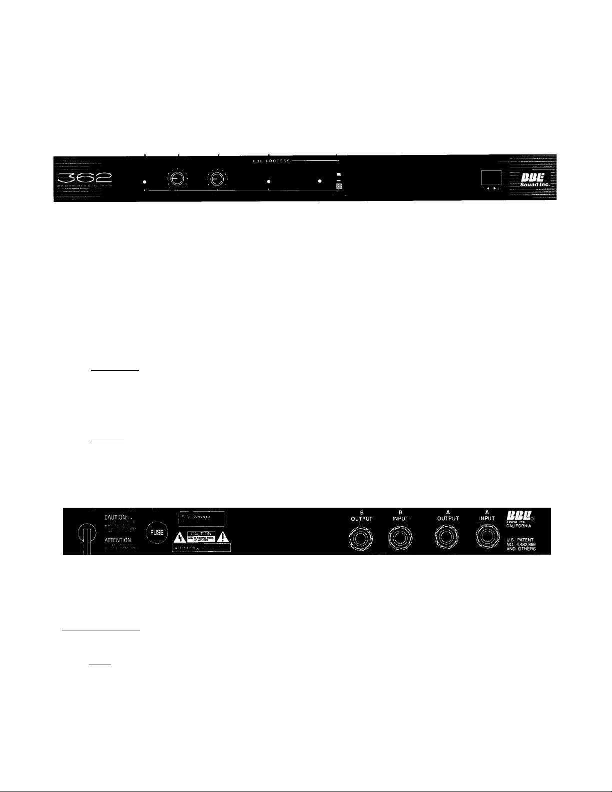
Rear Panel
L AC POWER CORD: Plugs into AC power receptacle. U.S. Model, 100-120Vac, 50/60Hz. Standard Model, 200-240Vac,
50/60HZ.
2. FUSE: Turn cap on fuse holder counter-clockwise to remove fuse. (Note: For U.S. Model, replace with 250Vac, 'hk
Fastblow type fuse. For standard Model, replace with 250Vac, .125A Fastblow type fuse.)
3- Each channel is equipped with a 14” phone jack that is a low impedance
unbalanced line level output and can deliver up to -l-16dBu into IK Ohms.
4. Each channel is equipped with a '4” phone jack that accepts a high impedance
unbalanced line level input with an average of -lOdBu. (Note: -f 16dBu is the maximum input before clipping.)
Page 6

APPLICATIONS
Music and P.A. Systems
The BBE 362 has become a popular addition to many P.A. systems because it makes a dramatic improvement to
the clarity of the vocals without the usual excessive brightness associated with equalizers. In addition, the intelligibility of
the monitor mix is greatly improved with the BBE process. To add the BBE process to the entire mix, insert the BBE 362
between the console output buss and the amplification stage in the P.A. System.
The BBE 362 unit is placed before any house graphic equalizers. All pink noise checks should be made with the
BBE units switched "out” to obtain the desired house curve. The BBE process is then dialed in to suit the music production.
Extreme console equalization normally used during live performance may be reduced due to the dynamic enhancement effect
of the BBE 362.
The BBE 362 has unbalanced inputs and outputs and the user should be aware of the level and impedance of the
insert point to insure proper operation on the BBE 362.
With this in mind, the BBE 362 may be inserted in any places within the console’s signal path to achieve specialized
and dramatic results. In the case of non-VCA sub-groups, the BBE 362 is inserted between "buss out" and "sub-group fader
in". If the BBE process is to be used on only one microphone source, the BBE 362 is inserted in the normal "insert send
and receive" points as a limiter or equalizer is patched.
Figure 1 shows the BBE 362 in a P.A. system application where both channels are used for the main house mix.
Figure 1A shows a powered mixer where the BBE 362 is inserted between the program out and graphic equalizer in. Figure
IB shows the BBE 362 in the insertion point of a mixing console for added clarity to that channel.
Home Studios
The BBE 362 gives a pro-edge to otherwise dull recordings on multi-track recorders. Snare drums and guitars take
on a brighter tonal quality without equalization. Tape tracks recorded without BBE can be processed after the fact by placing
the BBE 362 between the tape track output and the mixer channel input. The BBE 362 saves poorly recorded low-level
instruments and brightens them without bringing up the tape hiss as equalizers do. The program transients are audibly
improved on just about any sound source because the BBE 362 reduces the mid-range "smear" and the associated masking
effects.
Figure 2, 2A and 2B show applications of the BBE 362 in a home studio. Figure 2 shows that when recording, the
BBE 362 is inserted between "buss out" and "tape track in." By monitoring the tape track the amount of processing can be
adjusted to suit your needs. Figure 2A illustrates the hook-up configuration for mastering a multi-track recording down to
a two-track format. This is a mixdown set up and can help restore lost clarity.
Figure 2B shows that when in playback, the BBE 362 can be applied to a previously recorded tape track by inserting
the BBE 362 between the tape track output and the mixer input.
Cassette Copies
Since the BBE 362 is a single-ended playback process without encoding or decoding, the stereo BBE 362 is inserted
between the master two-track and the cassette recorder for punchier and crisper cassette copies. If you are very carefixl of
the amount of processing you are using and know the material, you should never have any trouble with "thin" sounding
copies. Figure 3 shows the BBE 362 in the cassette copy mode.
Page 7

APPLICATIONS
LEFT
RIGHT
Figure 1: Live Sound System
Page 8

APPLICATIONS cont.
MICROPHONES
MICROPHONE
Figure 1B: Powered Mixer System Application
Page 9

APPLICATIONS coni.
Figure 2: Recording Home Studio Application
Page 10

APPLICATIONS cont.
4-TRACK
Figure 2A: Recording Mix Down
Page 11

APPLICATIONS cont.
TAPE DECK
MIXING CONSOLE
0©
o
LINEIN(L&R)
Figure 2B: Playback/Home Studio Application
CASSETTE RECORDER
o o
OUT IN OUT IN
362 9 9 9 9
Figure 3: Cassette Copies
Page 12

SPECIFICATIONS
Frequency Response
Bypass............................................................................. DC to 20kHz
Process............................................................................ program controlled
Absolute Noise in Process Mode
Total Harmonic Distortion in Process Mode
Input Characteristics
Input Impedance...............................................................50K Ohms
Nominal Input Level
Output Characteristics........................................................ +16dBu
Minimum Load Impedance for full output level
Nominal Output Level.................................................... -lOdBu
Maximum Ouqjut Level................................................. + 16dBu
.......................................
....................
........................................................
............
Note: Due to continuing product improvement, specifications and design are subject to change withoitf notice.
-90dfiubelowratedmaxoutput
of OdBu
less than 0.1 %@*10dBu level
-lOdBu
IK Ohm
Power Requirements
U.S. Model
Standaid Model.............................. 200-240Vac, 50/60Hz, 10 Watts
AC Line fuse protected..................... U.S. Model; 250Vac/ViA Fastblow type fuse
Terminations/Connectors-rearpancl V4" Phone jacks
Dimensions....................................... Standard lU single rack
Weight
Note; OdBu = 0.775 Vims
.....................................
............................................
100-120Vac,50/60Hz, 10 Watts
StandardModel: 250Vac/. 125 AFastblow type fuse
l^"Hxl9"Wx5%"D
.
4'A lbs. (2.5Kgs)
Service
We recommend that if at all possible, a BBE 362 which requires service be sent to our facility in Huntington Beach, California. We
request that a "RETURN AUTHORIZATION" be issued by the dealer from whom you purchased the unit. If this is not possible, call
BBE Sound, Inc. directly (714) 897-6766, to obtain a "RETURN AUTHORIZATION", include a copy of the bill of sale with the unit
when it is shipped to BBE Sound, Inc. so that the service can be expedited.
As the repair turnaround time is minimal, we request that the unit be sent to BBE Sound, Inc. We also need to add reliability data
to our files so that future revision may be undertaken, if necessary, to improve the product.
Warranty
Warranty registration of the unit to BBE Sound, Inc. is not necessary. It is strongly recommended that you retain a copy of the bill of
sale for future reference.
IT IS THE SOLE RESPONSIBILITY OF THE END USER TO PROVIDE THE BILL OF SALE OR OTHER MEANS OF
PROOF OF PURCHASE TO VALIDATE THE WARRANTY IF WARRANTY SERVICE IS REQUESTED.
The BBE 362 is warranted against defects in material and workmanship for a period of five (5) years from date of purchase from BBE
Sound Inc. or from an authorized dealer. During this period, we will repair units free of charge providing that they are shipped prepaid to
BBE Sound, Inc. 5381 Production Drive, Huntington Beach, CA 92649. We will pay return UPS shipping charges within the USA. All
charges related to non-UPS shipping, including customs clearance, will be billed. The warranty will be honored for the longer of either 90
days from the date of any service or the remainder of the original 5 Year factory warranty.
This warranty will be consider null and void by BBE Sound, Inc. if any of the following is found:
1. The equipment has been physically damaged.
2. The equipment shows signs of abuse.
3. The equipment has been electrically damaged by improper connection or attempted repair by the customer or a third party.
4. The equipment has been modified without authorization.
5. The bill of sales indicates that the purchase date of the equipment is not within the warranty period.
All non-warranty repairs are warranted for a period of 90 days from the date of service.
BBE Sound, Inc. is NOT LIABLE FOR CONSEQUENTIAL DAMAGES. Should the unit fail to operate for any reason, our sole obligation
is to repair it as described above.
DO NOT RETURN ANY PRODUCT TO THE ABOVE ADDRESS WITHOUT INSTRUCTIONS AND AUTHORIZATION ISSUED BY
THE ABOVE LOCATION.
Maintenance
Maintenance of the BBE 362 is limited to proper cleaning of the unit with mild household cleaner such as Formula 409™ or Windex™,
The chassis and cover are steel finished with a durable polyurethane paint, while the front panel is an anodized aluminum extrusion.
There are no user replaceable parts and the unit should not be opened for any reason unless you are a qualified technician. Calibration
should be performed if parts are replaced or if a performance check-out indicates a problem with calibration. Long term use has shown
that over the life of this unit there is little or no drift of the components in the BBE 362 which would cause a change in calibration. A
very conservative design philosophy has resulted in a piece of equipment which runs very cool and should give years of trouble-free
10
Page 13

CALIBRATION PROCEDURES FOR THE BBE 362
NOTE: THIS UNIT WAS CALIBRATED AT THE FACTORY. THIS PROCEDURE IS FOR
QUALIFIED SERVICE PERSONNEL ONLY.
INITIAL SETTINGS:
1. BBE Process control VR2 and Lo Contour control VRl to minimum (fully C.C.W.).
2. Power switch on and Function switch in (Process on).
POWER SUPPLY TEST:
1. With DVM set to DC volts, measure the positive end of Cl. You should read less than +30 VDC.
2. With DVM set to DC volts, measure the negative end of C2. You should read less than -30 VDC.
3. Measure DC voltage on IMP 4. Reading should be +12 VDC, (+/1.5 VDC).
4. Measure DC voltage on IMP 11. Reading should be -12 VDC, (+/1.5 VDC).
BBE PROCESS TEST:
1. Input a 5kHz signal @ -lOdBu into Channel A [B] input.
2. Measure the Channel A [B] output with the DVM set to AC volts.
3. With Process control at minimum (fully C.C.W.), DVM should read -lO.SdBu (+/- 0.5dBu).
4. With Process control at maximum (fully C.W.), DVM should read -2dBu (+/- 0.5dBu).
LO CONTOUR TEST:
1. Input a 50Hz signal @ -lOdBu into channel A [B] input.
2. Measure the channel A [B] output with the DVM set to AC volts.
3. With Lo Contour control at minimum (fully C.C.W.) DVM should read -lOdBu (+/- 0.5dBu).
4. With Lo Contour control at maximum (fully C.W.) DVM should read -l.SdBu (+/- 0.5dBu).
BYPASS TEST:
1. Input a 500Hz signal @ -lOdBu into channel A [B] input.
2. Measure the channel A [B] output with the DVM set to AC volts.
3. With the Process in, the DVM should read -lldBu (+/- 0.5dBu) and the Process LED should
illuminate green.
4. With the Process out, the DVM should read -lO.SdBu (+/- 0.5dBu) and the Process LED should
illuminate red.
CLIP INDICATOR TEST:
1. Input a 500Hz signal @ +15dBu into the channel A [B] input.
2. Verify that the channel A [B] clip indicator is on.
3. Change signal input level to +13dBu and verify that the channel A [B] clip indicator turns off.
END TEST
11
Page 14

POWER SUPPLY CIRCUIT
CLIP CIRCUIT CHANNEL A
CLIP CIRCUIT CHANNEL В
------------
i----------------3
-------
T
BBE Sound« Zncorporatod
SSOO Bol*« Avenue
Huntlnaton Beech, Cellfornie 92649
Titl
BBC 362 POWER SUPPLY AND CLIP CIRCUITS
151ТГ
Docum#nt Numbtr
в
ВТПГ
riLE = 362POW.SCH
•F«^ru.r:~;s. BFiVf
T
•g of"
P?E7
12
Page 15

1
DXO
1N4146
JKi
R6
iK
~l
D9 4
1N4X46
<2Zo:
D&
.1N4148
'1.0uf/25V NP
V- V+
BBE Proc»t« 1« DEFEPTED uh«n V+ 1« applied
CPROCESS IS ENCPiED WHEN IN THE "OUT" POSITION?
1
|220pf
£ 019
0.0047uf C17
VRl
100
b Cil
220pf
___________e___
lb.047u
2
<
10uf/25V
2
1
C27
1 ^
lO.OOiuf
02S|| 4
>>
J_4.7wf/2SV NP
1023 s
l2.2uf/25V NP
021 II 6
1 1
2.2uf/25V NP
1 7
1
1.0uf/25V NP
_____l\___2___
<»7uf/25V
__ __
jia_
r
12
1 13
___
ii—
IS
2.2uf/25V NP
1
2
3 30
4
5 28
8
7
8
9
10 23
11 22
12
13 20
14 19
16
32-
32
31
22.
90 C26 |i4.7uf/25V NP
29
aa_
12_
27
26
1.0wf/25V NP i
2S-
2S
24
C28 iiO.OOluf
02« ||2.2uf/25V NP
C22 ||2.2wf/25V NP
0.47uf/25V
¿2-
21
21
20
____
^13
____
-Ifi
_________________________
ir.
17
030 1/ 1.0uf/25V
1
/C18
>‘0.047uf
s
'.N
VRIB
lOOK
220pf
1
=i= C16
______
C12 Z
T
-f- C32 I DU
I 220pf Z AN4148
0.0047
,
i.0uf/25V NP
CIO ,,
_
<2nEE>
<'iLIP t>
<2lies:
D12
1N4146
R7
IK
CHASSIS CROUNO
BBE CIRCUIT CROUND
08
.1N4X48
R5
IK
07
’ 1N4148
Peuar SlippIv. and Clip Cireultl
:SEE PAGE 2
34SP4W.S4H
i:
sw
1
JK4_
jO-j '
R15
lOOK
1
BBE Sound Incorporated
SSOO Bolea Avenue Suite *24S
Huntington Beach, California 92649
Title
B
Date
BBE 362 SONIC MAXIHIZER
Document Number
February 23, 1993ISheet 1 of
R3
3.3K Proc*«« £ng«9ed
51B
i/2 OPDT-OUT
-4c
R2
2.2K
RED 2a Screen
Di3
DUAL COLOR LED
REV
FILE = 362 A
2
Page 16

Sound Inc.
5381 Production Drive
Huntington Beach, CA 92649
714-897-6766 • FAX 714-896-0736
www.bbesound.com
covered by U.S. Patent 4,482,866 and other U.S. and foreign patents pending.
BBE is the registered trademark of BBE Sound, Inc.
 Loading...