BAYLI B1582T-ADJ, B1582T-5, B1582T-3.3, B1582T-3.0, B1582J-3.0 Datasheet
...
Bay Linear
Inspire the Linear Power
4.0A Low Dropout Voltage Regulator |
|
B1582 |
Adjustable & Fix Output |
|
|
Description
The Bay Linear B1582 is Monolithic low power 4.0A Adjustable and fixed NPN voltage regulator that are easy to use with minimum external components. It is suitable for applications requiring a well-regulated positive output voltage with low input-output differential voltage requirements and output voltage 1.5V, 2.5V, 3.0V, 3.3V, or 5V.
The B1582 Outstanding features include full power usage up to 4.0Amp of load current internal current limiting and thermal shutdown. Other fixed versions are also available consult with factory.
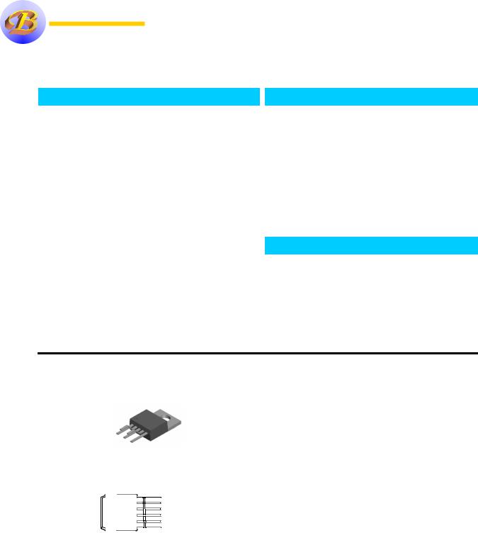
The B1582 is offered in a 5-pin TO-220, & TO-263 packages compatible with other 5 terminal regulators. The B1582 is offer in a new LPDD (Low Profile TO-263) package from 4.47 mm (DD) thickness down to only 1.27 mm (LPDD) total thickness.
Features
•Adjustable Output Down to 1.2V
•Fixed Output Voltages 2.5V, 3.0V 3.3V, and 5.0V
•Output Current of 4.0A
•Low Dropout Voltage 700mV Typ.
•Current & Thermal Limiting
•Standard 3-Terminal Low Cost TO-220, D2 Packages & LPDD
•Similar to industry Standard CS1503/EZ1582/IRU1150
Applications
•3.3V to 2.5V for Pentium Processor
•SMPS Post Regulator
•High Efficiency “Green” Computer Systems
•High Efficiency Linear Power Supplies
•5V to 3.XXV for Pentium Processor
•3.3V to 2.7V Intel I740 Chip Set
Pin Connection
5 VPOWER |
|
4 |
VCONTROL |
3 |
OUTPUT |
2 |
ADJ/GND. |
1 SENSE |
|
TO-263-5 Package |
|
Ordering Information
Devices |
Package |
Temp. |
B1582T |
TO-220 |
0 °C to 70 °C |
B1582S |
TO-263 |
0 °C to 70 °C |
B1582J |
LPDD |
0 °C to 70 °C |
Bay Linear, Inc 2418 Armstrong Street, Livermore, CA 94550 Tel: (925) 606-5950, Fax: (925) 940-9556 |
www.baylinear.com |
|
|
|
|
|
|
|
|
|
|
|
|
|
|
|
B1582 |
|
|
|
Absolute Maximum Rating |
|
|
|
|
|
|
|
|
|
|
|
|
|
|
||
|
Parameter |
|
|
Symbol |
|
|
|
Value |
|
|
|
|
Unit |
|
|
||
|
Maximum Input Voltage |
|
|
VIN |
|
|
7 |
|
|
|
|
|
V |
|
|
||
|
Power Dissipation |
|
|
PO |
|
|
Internally Limited |
|
|
W |
|
|
|||||
|
Thermal Resistance Junction to Case |
|
θJC |
|
|
3 |
|
|
|
|
|
°C/W |
|
|
|||
|
Thermal Resistance Junction to |
|
θJA |
|
|
50 |
|
|
|
|
|
|
|
|
|||
|
Ambient |
|
|
|
|
|
|
|
|
|
|
|
|
|
|
|
|
|
Operating Junction |
|
|
TJ |
|
|
|
|
|
|
|
|
|
|
°C |
|
|
|
Temperature Range |
|
|
|
|
|
|
|
|
|
|
|
|
|
|
|
|
|
Control Section |
|
|
|
|
|
0 to 125 |
|
|
|
|
|
|
|
|||
|
Power Transistor |
|
|
|
|
|
0 to 150 |
|
|
|
|
|
|
|
|||
|
Storage Temperature Range |
|
TSTG |
|
|
-65 to 150 |
|
|
|
|
|
|
|
||||
|
Lead Temperature (Soldering 10 |
|
TLEAD |
|
|
260 |
|
|
|
|
|
|
|
|
|||
|
Sec.) |
|
|
|
|
|
|
|
|
|
|
|
|
|
|
|
|
|
Electrical Characteristics |
|
|
|
|
|
|
|
|
|
|
|
|
|
|
||
|
(VIN = 2.05V to 5.25V; IO = 10mA to 4.0Amp, unless otherwise specified) |
|
|
|
|
|
|
|
|||||||||
|
Parameter |
Symbol |
Conditions |
|
|
|
|
|
|
MIN |
|
TYP |
|
MAX |
UNIT |
|
|
|
Output Voltage |
VO |
VCONT=4V, VPWR=2V |
|
|
|
|
1.485 |
|
1.5 |
|
1.515 |
V |
|
|||
|
|
|
|
VCONT=3V, VPWR=2.3V, ILOAD=10mA to 4A |
|
1.475 |
|
|
|
1.525 |
|
|
|||||
|
|
|
|
VCONT=5V, VPWR=3.3V |
|
|
|
|
2.475 |
|
2.5 |
|
2.525 |
|
|
||
|
|
|
|
VCONT=4V, VPWR=3.3V, ILOAD=10mA to 4A |
|
2.460 |
|
|
|
2.540 |
|
|
|||||
|
|
|
|
VCONT=5.5V, VPWR=3.5V |
|
|
|
|
2.970 |
|
3.0 |
|
3.030 |
|
|
||
|
|
|
|
VCONT=4.5V, VPWR=3.8V, ILOAD=10mA - 4A |
|
2.950 |
|
|
|
3.050 |
|
|
|||||
|
|
|
|
VCONT=5.8V, VPWR=3.8V |
|
|
|
|
3.267 |
|
3.3 |
|
3.333 |
|
|
||
|
|
|
|
VCONT=4.8V, VPWR=4.1V, ILOAD=10mA - 4A |
|
3.247 |
|
|
|
3.353 |
|
|
|||||
|
|
|
|
VCONT=7.5V, VPWR=5.5V |
|
|
|
|
4.950 |
|
5.0 |
|
5.050 |
|
|
||
|
|
|
|
VCONT=6.5V, VPWR=5.8V, ILOAD=10mA4A |
|
4.920 |
|
|
|
5.080 |
|
|
|||||
|
Reference Voltage |
Vref |
VCONT=2.75V, VPWR=2V, ILOAD=10mA |
|
1.238 |
|
1.250 |
|
1.262 |
V |
|
||||||
|
|
|
|
VCONT=2.7V, to 12V |
|
|
|
|
1.230 |
|
|
|
1.270 |
|
|
||
|
|
|
|
VPWR=3.3V to 5.5V, ILOAD=10mA to 4A |
|
|
|
|
|
|
|
|
|||||
|
Line Regulation (1) |
REG (line) |
IO = 10mA, VIN =5V, T= 25 °C |
|
|
|
|
|
|
0.04 |
|
0.2 |
% |
|
|||
|
|
|
|
|
|
|
|
|
|
|
|
|
|
|
|||
|
Load Regulation (1) |
REG (LOAD) |
IO = 10mA, VIN =5V, T= 25 °C |
|
|
|
|
|
|
0.08 |
|
0.40 |
|
|
|||
|
|
|
|
|
|
|
|
|
|
|
|
|
|
|
|||
|
Dropout Voltage |
VPWR-VOUT |
VCONT=VOUT+2.5V, ILOAD=1.5A |
|
|
|
|
|
|
0.26 |
|
0.38 |
|
|
|||
|
|
|
|
VCONT=VOUT+2.5V, ILOAD=3.0A |
|
|
|
|
|
|
0.50 |
|
0.70 |
V |
|
||
|
|
|
|
VCONT=VOUT+2.5V, ILOAD=4.0A |
|
|
|
|
|
|
0.70 |
|
0.80 |
|
|
||
|
Minimum load Current |
Imin |
|
|
|
|
|
|
|
|
|
5 |
|
10 |
mA |
|
|
|
Current Limit |
IS |
(Vin-Vout)=3V |
|
|
|
|
|
|
3 |
|
5 |
|
|
A |
|
|
|
Ground Pin Current |
IQ |
VIN =5V |
|
|
|
|
|
|
|
|
5 |
|
10 |
mA |
|
|
|
Temperature Stability |
TS |
IO = 10mA, VIN =5V |
|
|
|
|
|
|
0.5 |
|
|
% |
|
|||
|
Thermal Regulation |
|
|
T= 25 °C, 30ms pulse |
|
|
|
|
|
|
0.003 |
|
|
%/W |
|
||
|
Ripple Rejection |
RA |
T= 25 °C, VIN =5V |
|
|
|
|
60 |
|
75 |
|
|
dB |
|
|||
|
Thermal Resistance |
- |
|
TO-220 |
Junction to Tab |
|
|
|
3.0 |
|
3.0 |
°C/W |
|
||||
|
|
|
|
|
Junction to Ambient |
|
|
|
60 |
|
60 |
|
|
||||
|
|
|
|
DD Package |
Junction to Tab |
|
|
|
3.0 |
|
3.0 |
|
|
||||
|
|
|
|
|
Junction to Ambient |
|
|
|
60 |
|
60 |
|
|
||||
|
Note: Output Switch tests are performed under pulsed conditions to minimize power dissipation |
|
|
|
|
|
|
|
|||||||||
|
|
|
|
|
|
|
|
|
|
|
|
|
|
|
|
||
|
Bay Linear, Inc 2418 Armstrong Street, Livermore, CA 94550 Tel: (925) 606-5950, Fax: (925) 940-9556 |
|
www.baylinear.com |
|
|||||||||||||

B1582
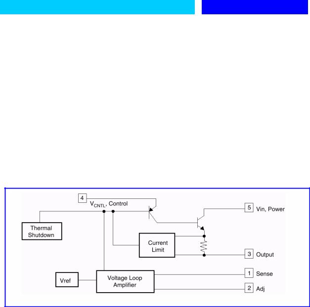
PIN DESCRIPTION
1.Sense = Allows Kelvin sense of VOUT at the load. (Positive side of the reference voltage of the device).
2.ADJ = Negative side of the reference voltage for the device. Adding a small bypass capacitor from the ADJ pin to ground will improve the transient response.
3.VOUT = Power output of the device.
4.VCTRL = Supply pin for the control circuitry of the device. The current flow into this pin will be about 1% of the output current. VCTRL must be between 1.0V and 1.3V greater than the output voltage for the device to regulate.
5.VIN = Output load current is supplied through this pin. VIN must be between 0.1V and 0.8V greater than the output voltage for the device to regulate.
BLOCK DIAGRAM
Bay Linear, Inc 2418 Armstrong Street, Livermore, CA 94550 Tel: (925) 606-5950, Fax: (925) 940-9556 |
www.baylinear.com |
 Loading...