


APH

BAYKAL
USER’S MANUAL
HYDRAULIC PRESS BRAKE
MODEL APH
No part of this User‘s Manual may be reproduced or transmitted by any without Prior permission of Baykal
Makine Sanayi ve Ticaret A.Ş.
EDITION NO : APH SECTION :
DATE OF ISSUE : July-2005 PAGE :
1

BAYKAL
MACHINE TYPE DESCRIPTION
APH XXXXX-xx
APH X X X X XXX
STANDARD
C – CE
S – STAND.
SUPPLY
VOLTAGE
1 – 220
2 – 230
3 – 240
4 – 400
5 – 415
6 – 440
7 – 480
8 – 600
9 – 220/400
CONTROLLER HYDRAULIC BLOCK ACCESSORIES
1 -- ELGO 8822
1 – FISSLER AKAS
2 – SICK LIGHT GUARD
3 – REER
4– LAZER SAFE
!
NOTE:
In order to SEE THE TYPE OF YOUR MACHINE, please
see the electric circuit diagram in APPENDIX C. It is written
in the left bottom side of the diagram.
EDITION NO : APH SECTION :
DATE OF ISSUE : July-2005 PAGE :
2

BAYKAL
! ATTENTION
PUMP ROTATION MUST BE IN
ARROW DIRECTION,
OTHERWISE
THE PUMP WILL BE DAMAGED
CHECK THE MOTOR ROTATION BY PUSHING THE ″ GREEN ″
START, AND IMMEDIATELY AFTER, THE (RED) STOP BUTTONS ON
THE ELECTRICAL PANEL. THE MOTOR MUST BE ROTATING IN THE
DIRECTION OF ″ARROW″. IF IT IS ROTATING IN THE REVERSE
DIRECTION, CHANGE ANY TWO PHASES IN THE ELECTRICAL
SUPPLY POINT.
EDITION NO : APH SECTION :
DATE OF ISSUE : July-2005 PAGE :
3

BAYKAL
INFORMATION AND WARNING LABELS
DESIGNATION PLATE
Manufacturer BAYKAL Mak. San. Tic. A.Ş.
Machine Hydraulic Press Brake
Type APH
Model
Serial No
Capacity ton
Bending length mm
Main voltage V/Hz/Ph
Motor Power kW
System Pressure bar
Min stroke mm
Max stroke mm
Machine weight kg
Top tool weight kg
Bottom tool weight kg
Length mm
Width mm
Bursa / TÜRKİYE
DESIGNATION PLATE BENDING TABLE
CE CONFIRMATION DANGER:
ELECTRIC SHOCK
GROUND LUBRICATION PUMP ROTATION
POINT
HANDS MAY BE WHEN BENDING, HANDS WHEN BENDING, SHEET
JAMMED MAY BE JAMMED BETWEEN MAY CRASH SOME PARTS
BETWEEN TOOLS TOP TOOL AND SHEET OF BODY
EDITION NO : APH SECTION :
DATE OF ISSUE : July-2005 PAGE :
4

BAYKAL
C O N T E N T S:
1. GENERAL MACHINE INFORMATION
1.1. Registered trademark
1.2. Machine type
1.3. Serial number
1.4. Year of manufacturer
1.5. Address of the manufacturer
1.6. Address of the authorized dealer
2. IMPORTANT INFORMATION
2.1. Safety features of your Press Brake
2.2. Important safety information & instructions
2.3. Noise Measurement
2.4. Stop Time Control
3. OVERALL DIMENSIONS and DRAWING
4. LIFTING & TRANSPORTATION
5. UNPACKING & INSTALLATION
6. OPERATING AND MAINTENANCE INSTRUCTIONS
6.1. Technical data
6.2. Description of Press brake applications
6.3. Prohibited uses of the Press brake
6.4. Incorrect uses of the Press brake
6.5.
Using The Press Brake
6.5.1. Requirements for the initial test and examination.
6.5.2.Electrical connections
6.5.3 Operating the Machine.
6.5.4.Centering the Bottom tool
6.5.5.Top beam parallelism adjustment
6.5.6.Backgauge parallelism adjustment
6.5.7.Changing Bending Tools
6.5.8.Wedge Adjustment
6.5.9. Manually Adjustable Crowning System (Optional)
6.5.10.Check-list of the finished product
6.5.11.Instructions for the press brake supervisor after machine set up
6.6. Maintenance and inspection
6.6.1. Type and frequency of inspections
6.6.2. Hydraulic System:
6.6.3. Changing oil:
6.6.4. Changing the filter:
6.6.5. Instructions to rescue persons jammed between press brake tools:
6.6.6. Stop time measurement:
6.7. Conditions of storage, re-utilization and scrapping
6.7.1. Storage
6.7.2. Reutilization after storage
6.7.3. Scrapping
7. LUBRICATION POINT
EDITION NO : APH SECTION :
DATE OF ISSUE : July-2005 PAGE :
5

BAYKAL
8. TROUBLESHOOTING
9. BENDING CHART
10. FOLDING FACILITIES
11. PRINCIPLES OF PRESS BRAKE BENDING TECHNOLOGY
APPENDIX
A. SPARE PARTS LIST
B. HYDRAULIC CIRCUIT DIAGRAM
C. ELECTRIC CIRCUIT DIAGRAM
ADDITIONAL MANUALS
ELGO P8822 Operating Manuel
A.
AKAS Laser guard User Manuel
B.
Wila Centrally Adjustable Crowning System (CVB/D)(Optional)
C.
EDITION NO : APH SECTION :
DATE OF ISSUE : July-2005 PAGE :
6

BAYKAL
1. GENERAL MACHINE INFORMATION
1.1. Registered trademark
1.2. Machine type
1.3. Serial number :
1.4. Year of manufacture
1.5.
Address of manufacturer:
: BAYKAL
: APH
:
BAYKAL MAKNE SAN.
TC. A..
Organize Sanayi Bölgesi
Yeşil Cad. No:24
BURSA - TURKEY
1.6. Address of the authorized dealer:
EDITION NO : APH SECTION :
DATE OF ISSUE : July-2005 PAGE :
7
BAYKAL
2. IMPORTANT INFORMATION
2.1. Safety features of your press brake
The electrical and hydraulic circuits of your press brake are designed to allow
operation with maximum safety. The following precautions are available on the
machine for enhanced safety.
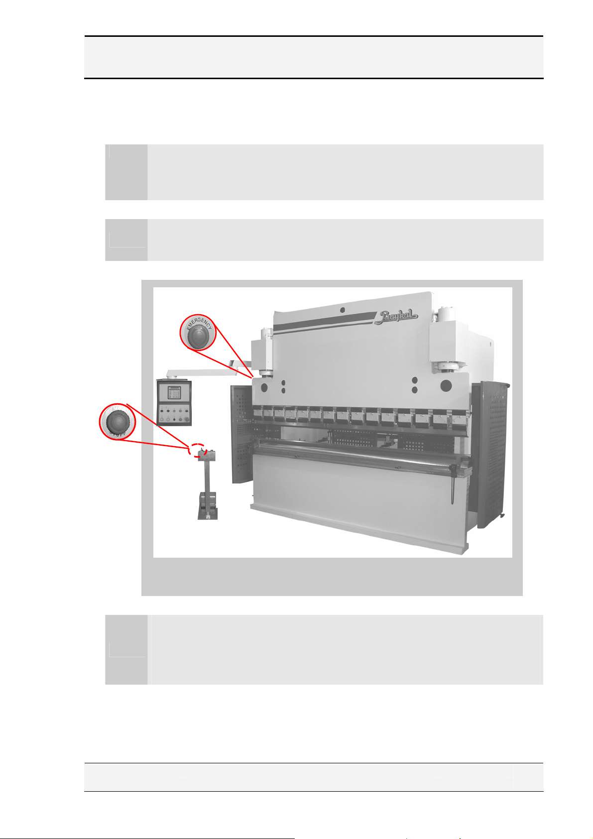
Emergency stop buttons (engaging type) are available on the control unit, on the
pedal control stand and on the electrical cabinet cover (see Figure 2.1.1).
•
Emergency Stop Buttons
Figure 2.1.1
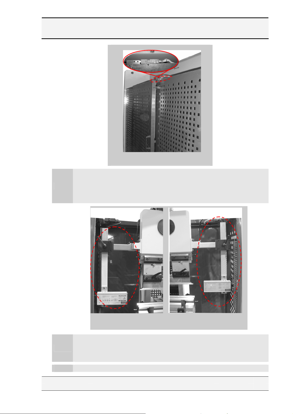
Electro-switch operated fence (See Figure 2.1.2) at the rear of the machine is
fitted. If any of these fences are opened when the beam is downstroking at fast
speed, the beam will retract automatically. If any of the fences are left open
•
before any operation, the operating modes of the machine are rendered nonfunctional.
EDITION NO : APH SECTION :
DATE OF ISSUE : July-2005 PAGE :
8
BAYKAL
•
•
•
Rear side of the machine
Figure 2.1.2
Fisler AKAS Laser guard (See Figure 2.1.3) mounted on the beam in front of
the machine protects operator from accidental contact with tooling when the
beam is in action. If anything access area between two devices (transmitter and
receiver) before the top beam reaches the muting point, the beam will stop and
retract automatically.
Transmitter Receiver
Left side of machine Right side of machine
Figure 2.1.3
In case of a power supply failure during operation, the beam will stop at a
standstill. When power supply is recovered, it is Not possible to start the
machine without resetting.
The cylinders are covered by fixed cover plates.
EDITION NO : APH SECTION :
DATE OF ISSUE : July-2005 PAGE :
9

BAYKAL
2.2. Important safety information & instructions
The machine must NOT be operated before reading this User’s Manual. Operate
the machine only if it is in a perfect condition and in accordance with the work
1.
regulations of your factory and operating instructions of this manual.
TRANSPORTATION! The lifting points are shown in the Lifting Diagram
2.
attached. The dimensions and the weight of the machine are given in section
6.1.1. of this manual.
INSTALLATION! The press brake is delivered in complete assembled
execution. It must be leveled and firmly stationed on the floor where it is to be
3.
used, according to the Installation Diagram attached. Indoor installation and a
dry working environment without danger of fire and explosion is necessary.
The permissible floor load, where the machine is to be installed,
!
must be accounted for.
The machine must be operated only by authorized and trained personnel.
Operation by unauthorized and untrained personnel in a way that does not
4.
comply with the instructions and regulations may lead to dangerous situations
and is strictly FORBIDDEN.
The press brake is designed such that it MUST be operated only by one operator.
5.
Using the machine with more than one operator is forbidden.
In case of any emergency, push the emergency stop buttons and follow the
6.
emergency rules of your factory.
The following instructions must be born in mind and be adhered to for safe
7.
operation and maintenance of your press brake :
This press brake is designed for bending only within the meaning
of section 6.2 of this manual regarding press brake applications.
!
Prohibited uses of the machine are dealt with in section 6.3 of this
manual.
DO NOT insert or extend your hands or arms in between bending
tools, under any circumstances, while the machine is in an
!
operational mode.
EDITION NO : APH SECTION :
DATE OF ISSUE : July-2005 PAGE :
10

BAYKAL
!
!
!
!
!
!
!
!
!
!
!
!
!
Check the machine daily for recognizable external damages and
defects.
Operate the machine only if all protective devices and guardings
are mounted and effective.
Take notice of the warning labels on the machine and do not
remove them.
In case of malfunction immediately shut down and secure the
machine. All troubles must be eliminated before re-starting.
Avoid any operation which may endanger other persons and
immediately shut down the machine when a danger is noticed.
Shut off the machine completely before any repair work is
carried out.
DO NOT let yourself be locked in the interior space of the
machine.
The safe distance of the two-hand control of this machine is 130
mm. Make sure that this safe distance is kept at all times.
DO NOT bridge the safety limit switches of the side and rear
protective fences.
DO NOT use front support arms for intermediate storage of
workpieces
During the bending process the workpiece may leap up.
Therefore, the material must be handled carefully.
All connecting bolts on the machine must be checked
periodically and be re-tightened if necessary.
When changing oil and replacing filter, the illustrations in
Section 6. 6 of this manual must be referred to. Make sure that
dirty filters are disposed separately.
The operating temperature rage of the oil is : (10°C - 65°C )
!
EDITION NO : APH SECTION :
DATE OF ISSUE : July-2005 PAGE :
11

BAYKAL
Any fire in the electric control system must be put out by using a
!
CO² fire extinguisher.
Any burning oil must be put out by using a CO² or powder
!
extinguisher.
All regulations concerning surface facilities designed for the use of
water polluting liquids must be observed in operation and
!
maintenance of this press brake.
All environmental regulations effective must be observed in use of
!
this press brake.
In the operation of the press brake no special personal safety equipment is
8.
necessary. It is however recommended to use working gloves when handling the
workpieces.
General maintenance of the press brake can be carried out by universal tools and
9.
equipment while the machine is at a standstill.
The manufacturer is free of any responsibility in case of any unapproved
10.
modifications made on the machine and /or any replacement of the original
safety and protective devices by unoriginal ones.
The machine is to be serviced and/or be repaired only by the authorized
11.
personnel of BAYKAL or its appointed representatives.
EDITION NO : APH SECTION :
DATE OF ISSUE : July-2005 PAGE :
12

BAYKAL
2.3. Noise measurement
The sound pressure level of the press brake at operator’s working position is
under 70 Db (A).
2.4. Stop time control
The stopping time of this press brake is 80 ms and the corresponding minimum
safety distance from the two-hand control is 130 mm.
EDITION NO : APH SECTION :
DATE OF ISSUE : July-2005 PAGE :
13
BAYKAL
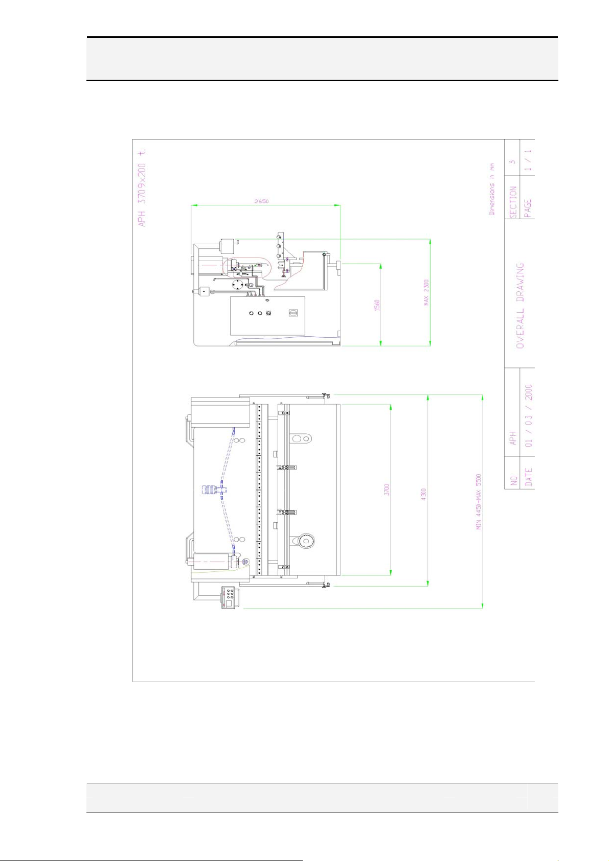
3. OVERALL DRAWING AND DIMENSIONS
Figure 3.1
EDITION NO : APH SECTION :
DATE OF ISSUE : July-2005 PAGE :
14
BAYKAL
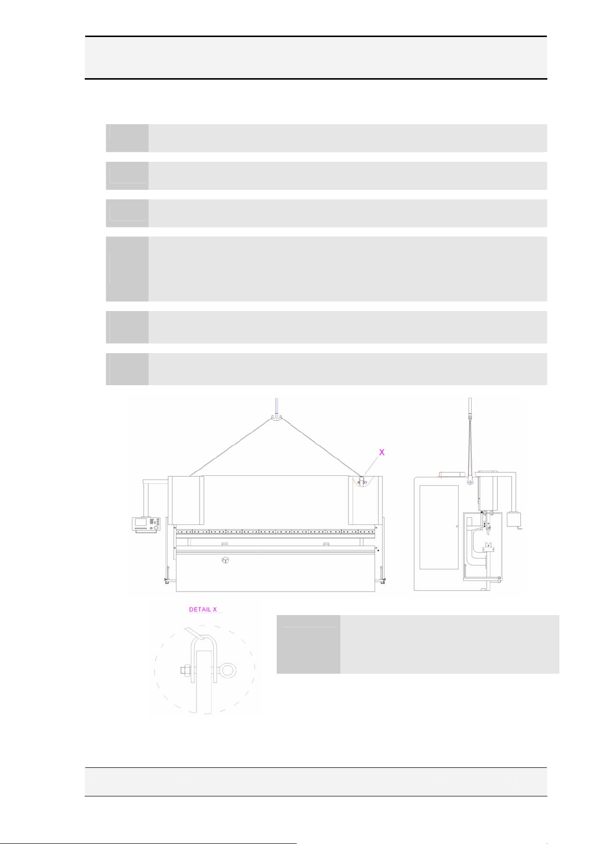
4. LIFTING & TRANSPORTATION
The following points should be taken into account :
The lifting points are illustrated in Figure 4.1.The dimensions and the weight of
•
the machine are given in section 6.1.1.of this manual.
Make sure that the lifting rope or chain is of sufficient capacity for the lifting
•
operation.
On press brakes the centre of gravity is on the front side.
Therefore, the machine must be handled with extreme caution
!
when lifting and installing to prevent it from inclining forward, or
even falling down.
Make sure that the machine is not subjected to impact
!
during loading or unloading.
The crane to lift the machine must be controlled by a single
!
operator.
WARNING
Figure 4.1
On press brakes, the center of gravity is on the
front side. Therefore the machine must be handled
with extreme caution when lifting and installing to
prevent it from inclining forward or even falling
down.
EDITION NO : APH SECTION :
DATE OF ISSUE : July-2005 PAGE :
15

BAYKAL
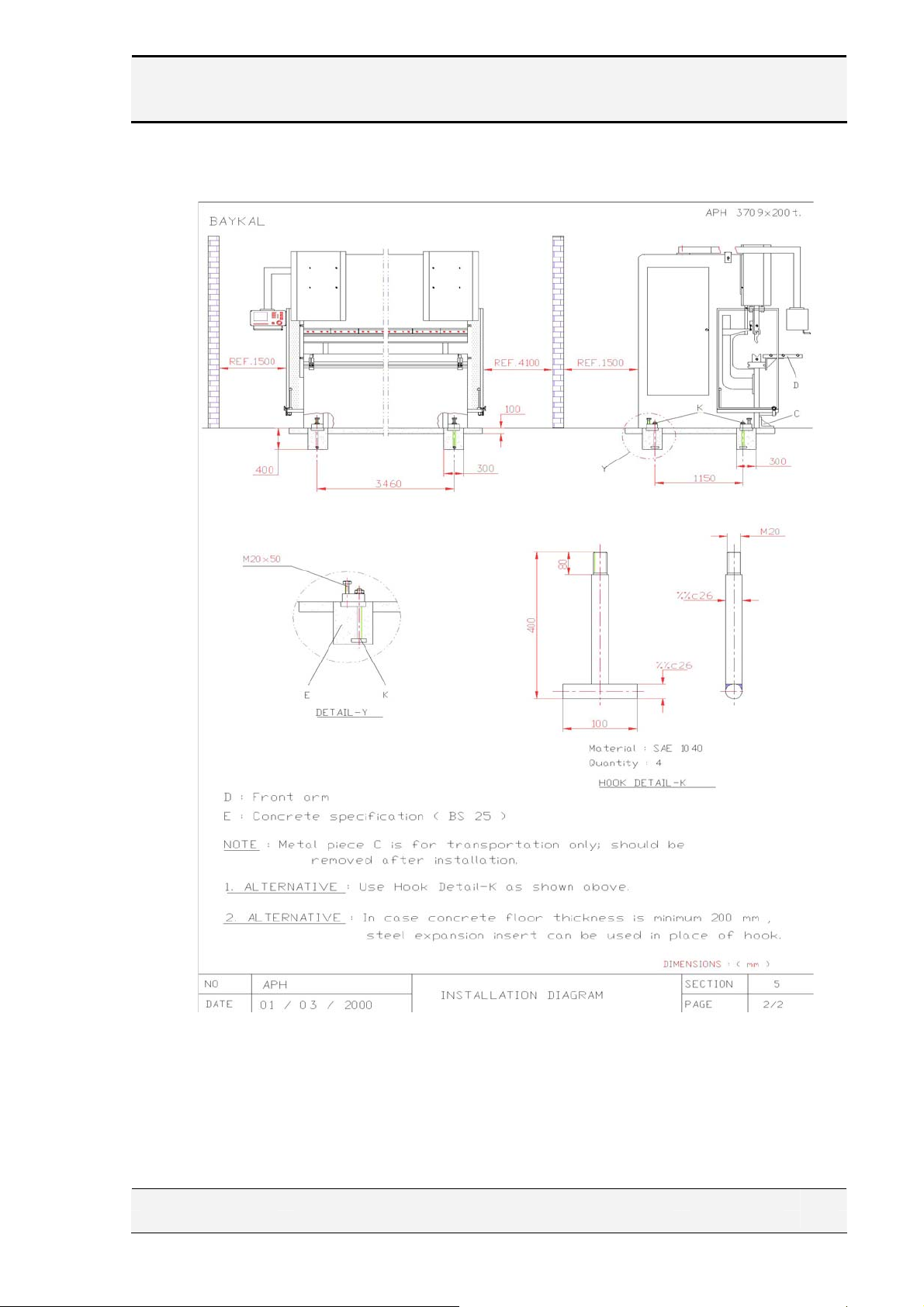
5. UNPACKING & INSTALLATION
The press brake is packed inside a nylon cover, and is bolted on wooden crates.
Prior to installation, dispose nylon and wooden crate separately and safely in
!
accordance with environmental regulations.
After unpacking, check the machine visually against any damage during
transport.
Install the machine in an indoor area which is free from humidity and excessive
dust.
Make sure that the machine is installed in accordance with the work and
maintenance space indicated in the enclosed Installation Diagram to enable the
operator to visualize the work area without obstruction. Therefore, the hazardous
!
situations regarding the operator, other persons, or materials due to incorrect
installation will be reduced.
It is important to leave a work space by both sides of the machine, which is not
less than the tool length. Otherwise, put a reminder that the tool change can only
be executed from the front of the machine.
Floor conditions for installation: Flat and concrete surface (BS 25).
Station the machine on the floor by anchorage bolts or steel expansion inserts as
illustrated in the Installation Diagram.
Remove the steel supports (Part ″C ″ in the Installation Diagram), and store
away for future use.
Level the machine by using a water level.
Mount the front support arms (Part ″ D″ ) as illustrated in the Installation
Diagram.
As the top and bottom tools are already fitted, the machine is now ready to
connect to an electric supply.
EDITION NO : APH SECTION :
DATE OF ISSUE : July-2005 PAGE :
16
BAYKAL
Figure 5.1
EDITION NO : APH SECTION :
DATE OF ISSUE : July-2005 PAGE :
17

BAYKAL
6. OPERATING AND MAINTENANCE INSTRUCTIONS
6.1. Technical Data
6.1.1. Specification:
1. Bending length mm
2. Bending capacity -St.42 mm
3. Bending force tons
4. Length mm
5. Width mm
6. Height mm
7. Weight kg
8. Approach speed mm / sec
9. Bending speed mm / sec
10. Return speed mm / sec
11. Total Stroke mm
-Piston Stroke mm
-Adjustment Stroke mm
12. Pump flow rate
13. Oil tank volume lt.
14. Back-gauge range mm
15. Main motor, 3 phase 380 V 50Hz kw
6.1.2. Standard Equipment:
Electric motor: 380 V 50 Hz 3phase
#
Standard top and bottom tools
#
Foot-pedal control system
#
Pendant control unit
#
Wedge system top tooling
#
750 mm. power back-gauge
#
Gearbox drive for cylinder stroke
#
Oil tank level indicator
#
Side and rear fence guarding
#
Hand screw clamps and chains for alignment and
#
rotation of bottom die.
cm³ / rev.
EDITION NO : APH SECTION :
DATE OF ISSUE : July-2005 PAGE :
18

BAYKAL
6.1.3. List of parts subject to rapid wear:
No Part name Size specification Qty.
1. Bottom tool - 1
2. Top tool - 1
3. Piston seal 2
4. Rod seal 2
5. Scraper 2
6. O-ring ( cylinder ) 2
6.1.4. List of bearings and special parts:
No Part name Part no. / description Qty. Location on machine
1. Axial bearing 2 Top beam
2. Radial bearing 2 Power back-gauge
EDITION NO : APH SECTION :
DATE OF ISSUE : July-2005 PAGE :
19

BAYKAL
6.2. Description of press brake applications
Your press brake is designed and constructed for press bending of
flat metal materials up to mm. length through use of hydraulic
pressure power of maximum tons which is adjustable. At
maximum tonnage, the material thickness that can be formed is mm.
in case of 42 kgs / mm² steel-plate, which is the most common
material processed on press brake.
The APH press brake is a downstroking type meaning that the
bending force is applied by a down-acting top beam, which is actuated
by two hydraulic cylinders. The lower beam is stationary. A set of top
and bottom tools must be used for bending. For an indication of
folding facilities and the type of tooling recommended, please see
section 10. Further information on the principles of press brake
bending technology is given in section 11.
EDITION NO : APH SECTION :
DATE OF ISSUE : July-2005 PAGE :
20

BAYKAL
6.3. Prohibited uses of the press brake
The press brake should not be used in the following circumstances:
If there is ANYTHING OTHER THAN THE WORKPIECE,
!
inserted, extended, put or placed in the working area between top and
bottom bending tools.
When any of the protective devices or guardings of the machine
!
are NOT mounted or NOT functioning.
For operations involving :
!
Cutting, punching, slitting, breaking crushing, drilling, imprinting
processes.
For bending operations involving non- flat metals (at origin).
!
e.g. rods, bars, tubes, pipes.
The manufacturer does not accept responsibility for personal safety
!
and for damage to the machine if the machine is used in prohibited
ways.
EDITION NO : APH SECTION :
DATE OF ISSUE : July-2005 PAGE :
21

BAYKAL
6.4. Incorrect uses of the press brake
During normal operation of the press brake, the following incorrect uses must be
avoided. The likely consequences of such incorrect uses are also explained
below :
Incorrect use ( 1 ) :
Consequence :
Incorrect use ( 2 ) :
Consequence :
Incorrect use ( 3 ) :
Consequence :
Top tool not centered on the bottom tool ″ V ″
• No bending at desired angle.
• Oil leakage in cylinder.
• Damage to tooling, breaking of tooling with possible
injury to operator.
• Breaking of stud connecting piston to beam.
Bending flame-cut material.
• Damage to tools, spread of chips from workpiece with
possible injury to operator.
During machine operation or adjustment, foreign substances
(e.g. nuts, bolts, wrenches and similar tools) lying in between
bending tools.
• Damage to bending tools, foreign substances breaking
out with possible injury to operator.
EDITION NO : APH SECTION :
DATE OF ISSUE : July-2005 PAGE :
22

BAYKAL
6.5. Using the press brake
6.5.1. Requirements for the initial test and examination
Check the machine visually against any transport damage.
•
Clean the oil tank.
•
Fill the oil tank up to the level indicator with one of the oil types recommended
•
in the Lubrication Diagram. (See section 7.)
Check that the side and rear guards are functioning mechanically in proper.
•
Check that the top tool is rigidly fixed in its place.
•
Check that the bottom tool is properly placed with respect to the top tool.
•
Make sure that the cables are not damaged.
•
Check the components and terminal ends inside the electrical cabinet against any
•
loosening.
Make sure that switches and buttons are not damaged.
•
Carry out the electrical connections according to section 6.5.2. and then proceed
•
with initial testing and start-up according to instructions in section 6.5.1. and
6.5.3.
Check by means of a test-run that :
•
a. All switches and buttons are fulfilling their functions. (In particular,
emergency, buttons, safety and limit switches).
b. There is no oil leakage in cylinders, valves, pipes and hoses.
EDITION NO : APH SECTION :
DATE OF ISSUE : July-2005 PAGE :
23

BAYKAL
6.5.2. Electrical connections
All electrical connections, however simple, must be carried out by
!
qualified electricians.
Machine must be placed as close as possible to an electricity supply point. In
cases where this is not possible, it is recommended to bring an auxiliary supply
duct alongside the machine. Electrics should be connected by supply cable with
correct diameter
!
EARTHING connection is strictly necessary.
Voltage and power requirements are labeled on the machine. First class
components are used in the electrical cabinet, and all electric wires are
numbered according to electric circuit diagram, and conform to established
standards. Cartridge fuses are used in the control circuit.
As the PEDAL control connections are already made in the factory, your
machine is now ready for initial start-up.
The machine must be first started-up and be put into Service by
!
authorized and qualified personnel.
WARNING:
Motor / pump rotation!
!
Check the motor/ pump rotation by pushing motor-start button, and
immediately after, motor-stop button on the Control pendant. The
motor must be rotating in the direction of ″arrow″ marked. If it is
rotating in the reverse direction change any two phases in the
electricity supply point.
EDITION NO : APH SECTION :
DATE OF ISSUE : July-2005 PAGE :
24
BAYKAL
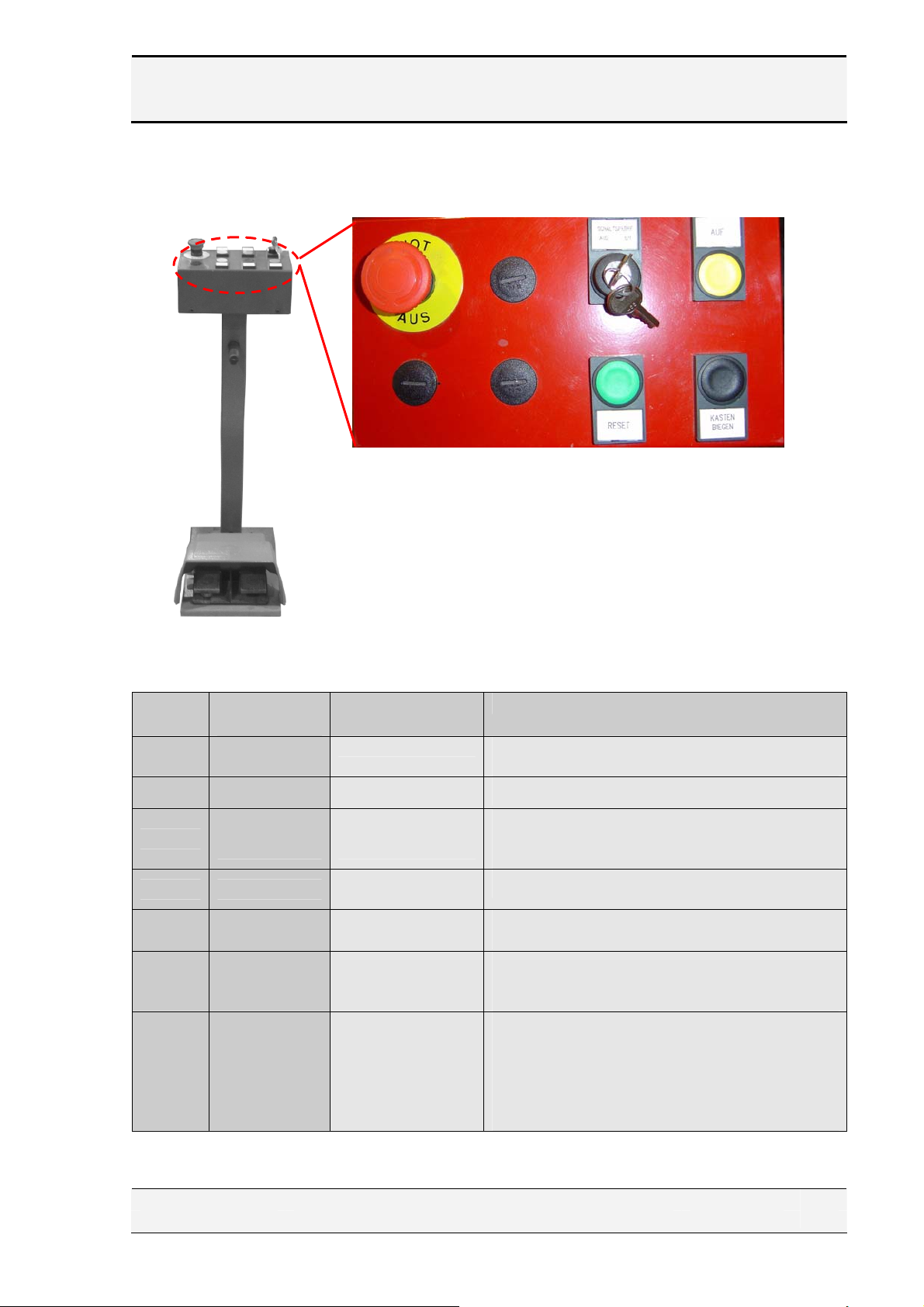
A. Pedal Connections
( d )
( f )
)
(e )
( g )
Mark Label
(a) 10S5
(b) 10S5A Right pedal
(c)
(d)
(e) 10S6
(f) Reset
(g)
(b) (a)
(Electr.Diag)
10S2
Figure 6.5.2.1
Designation Description
Left pedal
Emergency stop
button
Operation
ON/OFF
Up
Box Bending
When left pedal is pressed, Beam goes
downwards
When left pedal is pressed, Beam goes upwards
In case of emergency, when this button is pressed,
the main pump and other active components of
machine stop.
It switches on/off pedal operation
When Up button is pressed, Beam goes up in the
Inching Mode
In order to restart the machine after light barrier is
activated on the machine, the reset button must be
pressed.
When bending box or box type products, this
button must be pressed. Thus you activate the box
bending function of the laser safety system and
laser beams configuration between the transmitter
and the receiver is changed. Finally laser beams
will NOT be interrupted because of box sides.
EDITION NO : APH SECTION :
DATE OF ISSUE : July-2005 PAGE :
25
BAYKAL
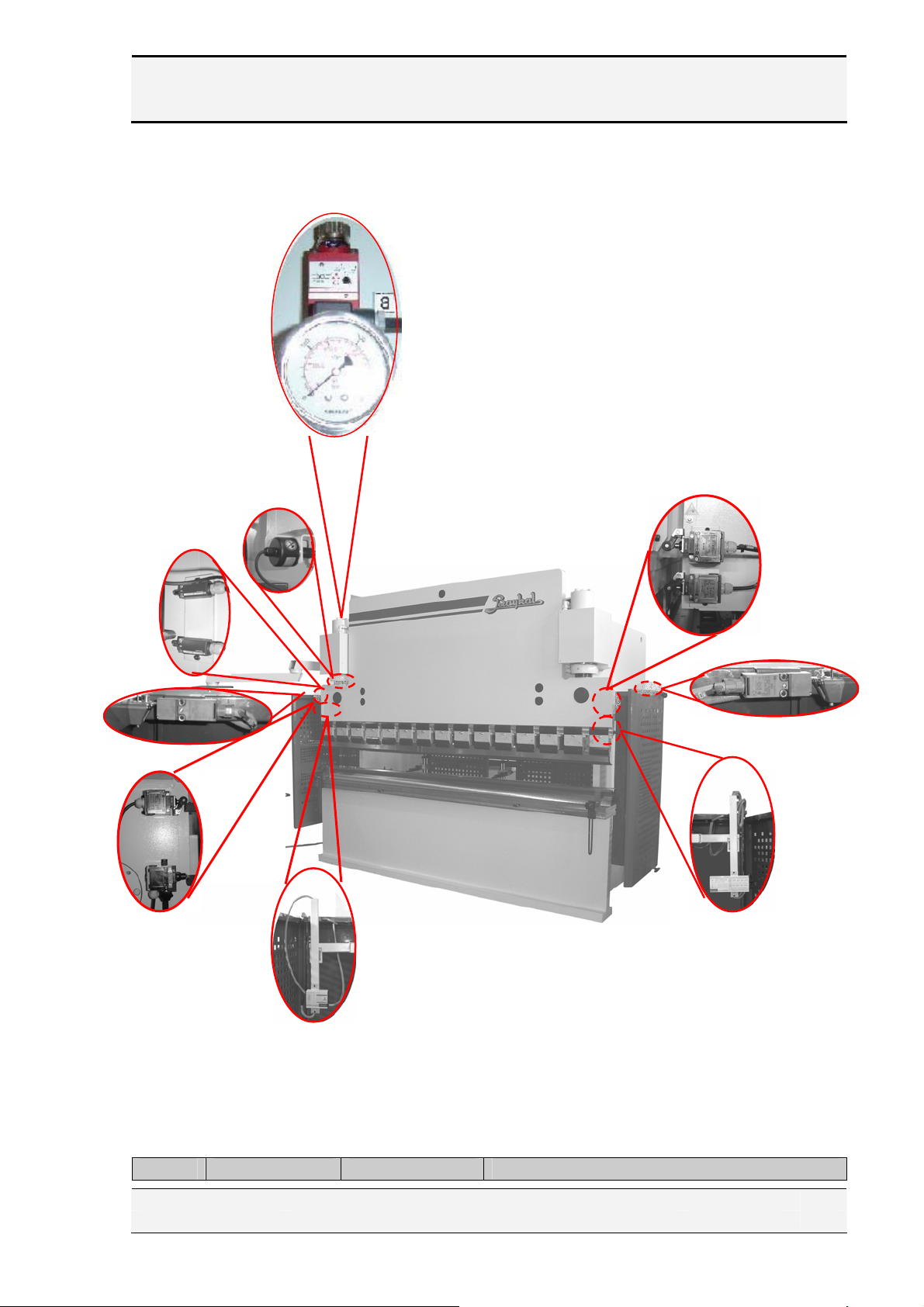
B. Front Connections
( j)
(k)
(i)
(c)
(d)
(e)
(l)
(f)
(a)
(h)
(b)
(g)
Figure 6.5.2.2
Mark Label Designation Description
EDITION NO : APH SECTION :
DATE OF ISSUE : July-2005 PAGE :
26

BAYKAL
(Electr.Diag)
(a) 11S1 UDP
(b)
(c) 11S3 Mute switch
(d) 11S2 Slowdown switch
(e) 13S4
(f) 13S3
(g) - Transmitter
(h) - Receiver
(i) 5B2 Reducer encoder
(j) 11S5 Pressure switch
(k)
(l)
11S4 Upper limit
Side guard safety
switch (Left side)
Side guard safety
switch (Right
side)
4S6 Limit switch
4S5 Limit switch
Upper dead point of Y axis. After Bending
process is completed, if you press right foot pedal,
beam goes upper dead point.
After each bending cycle in order to save time the
beam goes to Upper limit instead of UDP (It can
be adjusted).
The beam stops at this position. Because There is
no slowdown switch, Beam stops hardly.
This switch reduces beam speed while the beam is
traveling down fast in Working mode 2
Safety switch and connection. This is used for
additional safety. When the side guard (door) is
opened, it sends a interrupt signal to the
Controller and thus pomp stop.
Safety switch and connection. This is used for
additional safety. When the side guard (door) is
opened, it sends a interrupt signal to the
Controller and thus pomp stop.
AKAS laser guard transmitter and electrical
connections. See the electric circuit diagram.
AKAS laser guard receiver and electrical
connections. See the electric circuit diagram.
It computes bending angle.
It adjusts bending pressure
Reducer maximum limit
Reducer minimum limit
EDITION NO : APH SECTION :
DATE OF ISSUE : July-2005 PAGE :
27
BAYKAL
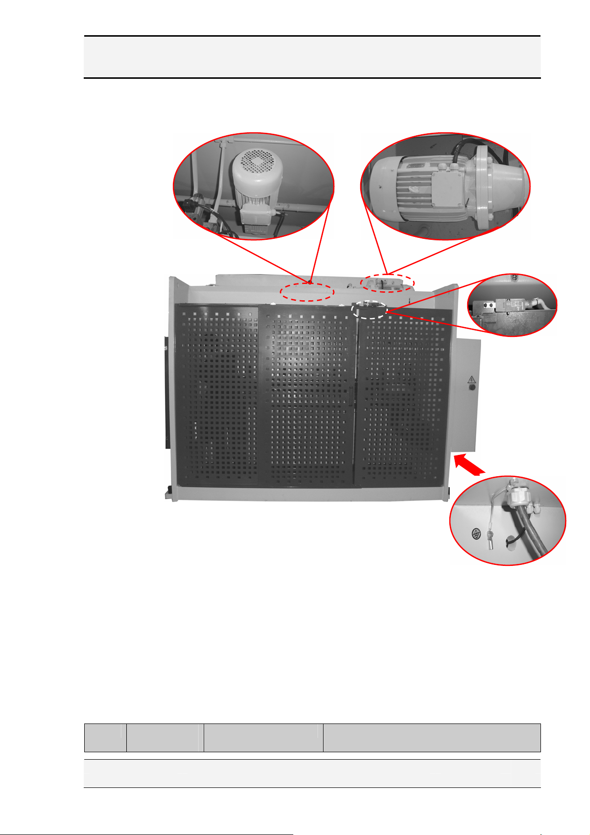
C. Back side connections
Mark Label
(Electr.Diag)
Designation Description
( a) ( b)
Figure 6.5.2.3
( c)
( e)
( d)
EDITION NO : APH SECTION :
DATE OF ISSUE : July-2005 PAGE :
28
 Loading...