

Page 1
SERVICE MANUAL
INSTALLATION INSTRUCTIONS
OV500-EE SERIES GAS RACK
OVENS AND OV500 SERIES
ELECTRIC RACK OVENS
OV500G1-EE ML-132518
OV500G2-EE ML-132525 (BEFORE MARCH 2015)
OV500E1 ML-132522
OV500E2 ML-132524 (BEFORE APRIL 2015)
OV500G2EE ML-132529 (AFTER FEB 2015)
OV500E2 ML-132531 (AFTER MARCH 2015)
- NOTICE -
This Manual is prepared for the use of trained Baxter Service
Technicians and should not be used by those not properly
qualified.
This manual is not intended to be all encompassing. If you have
not attended a Baxter Service School for this product, you should
read, in its entirety, the repair procedure you wish to perform to
determine if you have the necessary tools, instruments and skills
required to perform the procedure. Procedures for which you do
not have the necessary tools, instruments and skills should be
performed by a trained Baxter Service Technician.
The reproduction, transfer, sale or other use of this Manual,
without the express written consent of Baxter, is prohibited.
This manual has been provided to you by ITW Food Equipment
Group LLC ("ITW FEG") without charge and remains the property
of ITW FEG, and by accepting this manual you agree that you will
return it to ITW FEG promptly upon its request for such return at
any time in the future.
A product of Baxter MFG. Co., Inc 19220 State Route 162 East Orting, WA 98360
F45469 Rev. D (1019)
Page 2

INSTALLATION INSTRUCTIONS OV500-EE SERIES GAS RACK OVENS AND OV500 SERIES ELECTRIC RACK
OVENS
TABLE OF CONTENTS
SERVICE UPDATES ....................................................................................... 3
SERVICE UPDATES - OV500EE SERIES ............................................................... 3
IMPORTANT FOR YOUR SAFETY ......................................................................... 4
IMPORTANT FOR YOUR SAFETY ..................................................................... 4
GENERAL .................................................................................................. 6
INTRODUCTION ....................................................................................... 6
GENERAL .......................................................................................... 6
HEATING .......................................................................................... 6
STEAMING SYSTEM ............................................................................... 6
UNPACKING ........................................................................................... 6
LOCATION ............................................................................................. 6
CLEARANCE DIMENSIONS ............................................................................ 6
TESTING THE GAS SUPPLY PIPING SYSTEM ......................................................... 6
INSTALLATION CODES AND STANDARDS ............................................................ 7
SPECIAL TOOLS ....................................................................................... 7
OV500G1-EE GAS OVEN SPECIFICATIONS ........................................................... 7
OV500G2-EE GAS OVEN SPECIFICATIONS .......................................................... 10
OV500E1 ELECTRIC OVEN SPECIFICATIONS ........................................................ 12
OV500E2 ELECTRIC OVEN SPECIFICATIONS ........................................................ 14
INSTALLING OVEN ....................................................................................... 17
OVEN SECTIONS ..................................................................................... 17
FLOOR / THRESHOLD ................................................................................ 27
STEAM SYSTEM ...................................................................................... 29
DOOR HANDLE ....................................................................................... 32
DOOR ASSEMBLY .................................................................................... 32
DOOR SWITCH ACTUATOR .......................................................................... 35
DOOR SWEEP ........................................................................................ 35
RACK CARRIER - A & C STYLE RACK LIFT ........................................................... 35
RACK CARRIER - B STYLE RACK LIFT ............................................................... 38
HOOD ASSEMBLY .................................................................................... 39
HOOD VENTING ...................................................................................... 42
AIR BAFFLE & GREASE FILTERS .................................................................... 43
CAULK OVEN ......................................................................................... 44
INITIAL START-UP .................................................................................... 44
INITIAL START-UP INFORMATION MATERIAL ........................................................ 48
FINAL CHECKS ....................................................................................... 49
© BAXTER 2017
F45469 Rev. D (1019) Page 2 of 49
Page 3

INSTALLATION INSTRUCTIONS OV500-EE SERIES GAS RACK OVENS AND OV500 SERIES ELECTRIC RACK
OVENS - SERVICE UPDATES
SERVICE UPDATES
SERVICE UPDATES - OV500EE SERIES
February, 2017
1. Update ML information on front cover.
Updated Anchor Point in
2.
3. Updated OVEN SECTIONS.
4. Updated FLOOR / THRESHOLD.
5. Updated STEAM SYSTEM.
6. Updated DOOR HANDLE.
7. Updated DOOR ASSEMBLY.
8. Updated HOOD ASSEMBLY.
9. Updated AIR BAFFLE & GREASE FILTERS.
IMPORTANT FOR YOUR SAFETY.
Page 3 of 49 F45469 Rev. D (1019)
Page 4
INSTALLATION INSTRUCTIONS OV500-EE SERIES GAS RACK OVENS AND OV500 SERIES ELECTRIC RACK
OVENS - IMPORTANT FOR YOUR SAFETY
IMPORTANT FOR YOUR SAFETY
IMPORTANT FOR YOUR SAFETY
THIS MANUAL HAS BEEN PREPARED FOR PERSONNEL QUALIFIED TO INSTALL GAS EQUIPMENT, WHO
SHOULD PERFORM THE INITIAL FIELD START-UP AND ADJUSTMENTS OF THE EQUIPMENT COVERED
BY THIS MANUAL
POST IN A PROMINENT LOCATION THE INSTRUCTIONS TO BE FOLLOWED IN THE EVENT THE SMELL OF
GAS IS DETECTED. THIS INFORMATION CAN BE OBATINED FROM THE LOCAL GAS SUPPLIER
IN THE EVENT OF A POWER FAILURE, DO NOT ATTEMPT TO OPERATE THIS DEVICE.
KEEP AREA AROUND OVEN CLEAR OF COMBUSTIBLES.
DO NOT OBSTRUCT COMBUSTION AND VENTILATION OPENING ON THE OVEN.
IMPORTANT
IN THE EVENT A GAS ODOR IS DETECTED, SHUT DOWN UNITS AT MAIN SHUTOFF VALVE AND CONTACT
THE LOCAL GAS COMPANY OR GAS SUPPLIER FOR SERVICE.
FOR YOUR SAFETY
DO NOT STORE OR USE GASOLINE OR OTHER FLAMMABLE VAPORS OR LIQUIDS IN THE VICINITY OF
THIS OR ANY OTHER APPLIANCE
WARNING
IMPROPER INSTALLATION, ADJUSTMENT, ALTERATION, SERVICE OR MAINTENANCE CAN CAUSE
PROPERTY DAMAGE, INJURY OR DEATH. READ THE INSTALLATION, OPERATING AND MAINTENANCE
INSTRUCTIONS THROUGHLY BEFORE INSTALLING OR SERVICEING THIS EQUIPMENT.
F45469 Rev. D (1019) Page 4 of 49
Page 5
INSTALLATION INSTRUCTIONS OV500-EE SERIES GAS RACK OVENS AND OV500 SERIES ELECTRIC RACK
OVENS - IMPORTANT FOR YOUR SAFETY
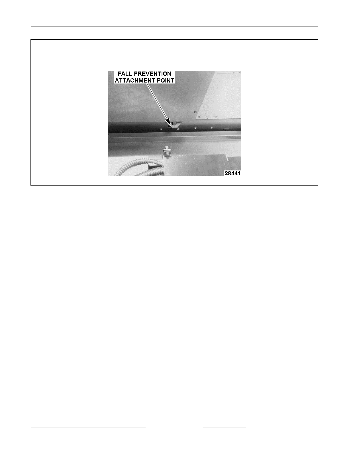
FOR YOUR SAFETY
AN ATTACHMENT POINT FOR FALL PREVENTION IS LOCATED ON TOP, IN THE CENTER OF THE OVEN.
WHEN WORKING ON TOP OF OVEN, BE SURE TO SECURELY ATTACH SAFETY HARNESS TO FALL
PREVENTION ATTACHMENT POINT.
Fig. 1
Page 5 of 49 F45469 Rev. D (1019)
Page 6
INSTALLATION INSTRUCTIONS OV500-EE SERIES GAS RACK OVENS AND OV500 SERIES ELECTRIC RACK
OVENS - GENERAL
GENERAL
INTRODUCTION
General
OV500G1-EE
rack and OV500G2-EE & OV500E2 rack ovens hold
two single racks or one double rack.
Oven features:
• Powered rack lift with high temperature bearings
and a clutch rotating system designed to stop the
rack in the event of a jam without damage to the
rotation motor or losing rack alignment.
• Digital programmable controller with optional
backup control, flush flooring, and field reversible
bake chamber door.
All of the information, illustrations and specifications
contained in this manual are based on the latest
product information available at the time of printing.
Heating
The rack oven reaches baking temperatures of 350°
in approximately 20 minutes; however, a 30 minute
preheat is recommended to fully heat the steam
generator.
Steaming System
Standard on all rack ovens, is a self-contained
spherical cast steam system providing excellent
steaming conditions.
& OV500E1 rack ovens hold one single
UNPACKING
Remove the crating from the oven exterior, check for
possible shipping damage. If the oven is found to be
damaged after unpacking, save the packaging
material and contact the carrier within 15 days of
delivery.
LOCATION
To reduce the risk of fire, the appliance is
to be installed on non-combustible surface only, with
no combustible material within 18 inches above the
appliance. The appliance is to be mounted on floors
of non-combustible construction with noncombustible
flooring and surface finish and with no combustible
material against the underside, or on non-combustible
slabs or arches having no combustible material
against the underside. Such construction shall in all
cases extend not less than 12 inches beyond the
equipment on all sides.
Oven not provided with a canopy hood, must be
installed under a ventilation hood.
The floor must be level with surrounding area with a
maximum slope of 1/8" per foot up to 3/4" maximum
in all directions. Floor anchors require a minimum 1"
thick solid floor substrate.
A level floor area must be prepared before assembling
oven. The floor area should be at least 104"D x 74"W
for double rack oven and 94"D x 57"W for single rack
oven, to accommodate the oven footprint and door
swing. Check the facilities floor area at the threshold
and door swing opening location to determine if
facilities floor will need to be reworked.
Do not obstruct the flow of combustion and ventilation
air. Keep the appliance area free and clear from
combustibles.
Make sure there is an adequate supply of make up air
in the room to allow for combustion.
The electrical diagram is located on the inside of the
heat exchanger compartment door.
NOTE: If the location has multiple ovens, keep the
serial numbered crates together.
Oven is UL/CSA Listed for zero clearance for back and
side
for plumbing rear drain connection.
Top of oven requires a minimum of 24" clearance for
servicing accessability.
TESTING THE GAS SUPPLY PIPING
When test pressures exceed 1/2 psig (14" W.C.)
(35.6cm W.C.) (3.5kPa), the oven and its individual
F45469 Rev. D (1019) Page 6 of 49
CLEARANCE DIMENSIONS
walls. A 1" to 4" back clearance is recommended
SYSTEM
Page 7

INSTALLATION INSTRUCTIONS OV500-EE SERIES GAS RACK OVENS AND OV500 SERIES ELECTRIC RACK
OVENS - GENERAL
shutoff valve must be disconnected from the gas
supply piping system.
test pressures are 1/2 psig (14" W.C.) (35.6cm
When
W.C.) (3.5kPa) or less, the oven must be isolated from
the gas supply piping system by closing its individual
shutoff valve.
INSTALLATION CODES AND
STANDARDS
OV500 ovens must be installed in accordance with:
United States
State and local codes.
1.
2. National Fuel Gas Codes, ANSI Z223.1 (latest
edition), available from American Gas
Association, 1515 Wilson Boulevard, Arlington,
VA 22209.
3. ANSI/NFPA 96, Standard for Ventilation Control
& Fire Protection of Commercial Cooking
Operations (latest edition), available from
National Fire Protection Association,
Batterymarch Park, Quincy, MA 02269.
4. National Electrical Code, ANSI/NFPA-70 (latest
edition).
5. NSF/ANSI 4 - 2007e Standard for Commercial
Cooking, Rethermalization and Powered Hot
Food Holding & Transport Equipment.
Canada
1. Local codes.
2. CAN/CGA-B149-1, Installation for Natural Gas
Burning Appliances and Equipment (latest
edition).
3. CAN/CGA-B149-2, Installation for Propane
Burning Appliances and Equipment (latest
edition).
4. Canadian Electrical Code, Part 2, CSA Standard
C22.1 (latest edition).
Plumbing Connections
1. Water and waste piping and connections shall
comply with the International Plumbing Code
2003, International Code Council (ICC), or to the
Uniform Plumbing Code 2003, International
Association of Plumbing and Mechanical
Officials (IAPMO).
NOTE: Plumbing connections must comply with
applicable sanitary, safety and plumbing codes and
provide adequate backflow protection to comply with
applicable federal, state and local codes.
SPECIAL TOOLS
• Inclined manometer - Dwyer Cat. #1227 or
equivalent.
Combustion analyzer meter Bacharach Fyrite
•
Pro 125 Bacharach model# 24-8105 or Fyrite
"Insight" model# 24-8251(Order from Bakery
Support).
• Rotary hammer / hammer drill to drill holes in floor
for anchor bolts.
• 3/8" masonry drill bit to drill holes in floor for
anchor bolts.
• Temperature tester (thermocouple type) with 10'
lead.
• Gauges for checking air shutters Part No. 011M5689-00001 (shipped with oven).
• Draft meter BACHARACH Model 13-3000 DCL
24490 or equivalent.
• Dolly wheel Part No. 01-1M2335-00001.
• Mini laser level self leveling with tripod Harbor
Freight No. 92703-OVGA.
• 2 ton foldable shop hoist Harbor Freight No.
35915-4VGA for lifting oven section.
• 3/8" chain 20 ft. long with a 4700 lbs. load rating
Harbor Freight No. 40461-7VGA used with hoist.
• Two 7/16" X 5-1/2" bolts used with hoist.
• Two 7/16" nuts used with hoist.
• Four 7/16" fender washers used with hoist.
• Loctite® #242 Part No. 00-520228
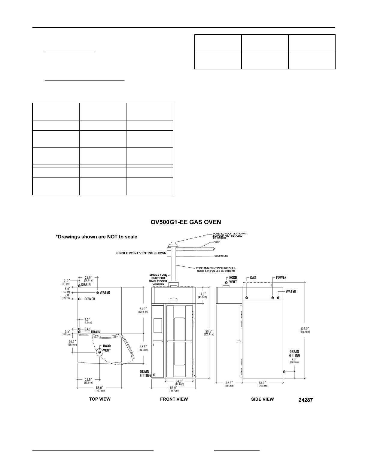
OV500G1-EE GAS OVEN
SPECIFICATIONS
1. WATER:
1/2" NPT, 30-75 PSI cold water required,
customer
line strainer.
2. DRAIN:
6 1/4" (front) or 7" (rear) connection A.F.F.
NOTES. Route to air-gap drain. Do not slope
drain upwards. Plug the drain connection that is
not in use.
Rear Drain: 1/2" NPTF
Front Drain: 1/2" NPTF
3. POWER:
to install in-line filter, shut off valve and
SEE
Page 7 of 49 F45469 Rev. D (1019)
Page 8
INSTALLATION INSTRUCTIONS OV500-EE SERIES GAS RACK OVENS AND OV500 SERIES ELECTRIC RACK
OVENS - GENERAL
Two supplies required. 120/60/1 20 AMP
dedicated circuit required and one of the
following voltage options.
Voltage Full Load AMPS
208 - 240/60/1 8.8 - 7.6 AMPS
208 - 240/60/3 5.0 - 4.4 AMPS
440 - 480/60/3 2.4 - 2.2 AMPS
4. GAS:
Natural Gas (N.G.)
NPT, W.C.N.G. (N.G. rated 1025 BTU/CU. FT.
1"
SP. GR. 1.00)
Liquified Propane Gas (L.P.G.)
1" NPT, W.C.L.P.G. (L.P.G. rated 2440 BTU/
CU.FT., SP. GR. 1.52)
Natural Gas
BTU/HR 180,000 180,000
INLET
PRESSURE
MANIFOLD
PRESSURE
5. HOOD VENT:
8" DIA connection collar. Customer to supply
and ventilator fan per state and local codes.
duct
Air proving switch factory installed & integrated
with burner system operation. Oven provided
relay with max. 10 amp 1/2 H.P. @ 120V output
for fan operation. If larger, use oven relay to
control additional separately powered contactor /
relay for hood fan. Chamber vents are factory
ducted to this integral hood. 690 CFM required,
0.6" W.C. static pressure drop through hood.
Hood is UL710 Listed when grease filters are
installed. Type B gas vent can be used except
when bake products are grease laden.
NOTES:
1. A.F.F.: Above finished floor.
2. Customer responsible to finish and install all
utilities to and from oven.
3. All services must comply with all Federal, State
and Local codes.
5.0" - 10.0" W.C.
3.5" W.C. 10.0" W.C.
Liquified
Propane Gas
12.0" - 14.0"
W.C.
To reduce the risk of fire, the appliance is
to be installed on non-combustible surface only, with
no combustible material within 18 inches above the
appliance. The appliance is to be mounted on floors
of non-combustible construction with non-combustible
flooring and surface finish and with no combustible
material against the underside, or on non-combustible
slabs or arches having no combustible material
against the underside. Such construction shall in all
cases extend not less than 12 inches beyond the
equipment on all sides.
4. The floor must be of non-combustible material,
and must be level with surrounding area with a
maximum slope of 1/8" per foot up to 3/4"
maximum in all directions. Floor anchors require
a minimum 1" thick solid floor substrate.
5. Oven is UL/C-UL classified and CSA (AGA/CGA)
approved for 0" clearance on the side and rear
walls. Unit requires 1" to 4" clearance for rear
drain connection.
6. Top of oven requires a minimum of 24" for service
accessibility.
7. Customer responsible to install flue piping. Flue
must be vented outside of building.
8. Manufacturer reserves the right to make changes
in sizes and specifications.
Export Ratings
1. WATER:
1/2" NPT, 2.1-5.2 Bar cold water required,
customer to install in-line filter, shut off valve and
line strainer. Flow rate of 8 l/min..
2. DRAIN:
6 1/4" (front) or 7" (rear) connection A.F.F. SEE
NOTES. Route to air-gap drain. Do not slope
drain upwards. Plug the drain connection that is
not in use.
Rear Drain: 1/2" NPTF
Front Drain: 1/2" NPTF
3. POWER:
Two supplies required. Control Circuit:
100/50/60/1 or 208-240/50/1
1 kVA transformer supplied for control circuit
operation voltage of 110V. This is a multifunction
transformer, so output voltage should be verified
before operation. Some wiring may be required
to obtain proper output voltage.
F45469 Rev. D (1019) Page 8 of 49
Oven fan (1.1kW) 200V/50-60Hz/3ph/5.3A or
380- 415V/50Hz/3ph/ 2.8 - 2.5A.
Page 9
INSTALLATION INSTRUCTIONS OV500-EE SERIES GAS RACK OVENS AND OV500 SERIES ELECTRIC RACK
OVENS - GENERAL
4. GAS:
Natural Gas (N.G.)
NPT (N.G. Rated 38.2Mj/m3 or 9120 Kcal/m3
1"
SP Gr 1.00)
Liquefied Propane Gas (LPG)
NPT (LPG Rated 90.9Mj/m3 or 21710 Kcal/m3
1"
SP Gr 1.52)
Natural Gas
RATING 45,400 Kcal/hr 45,400 Kcal/hr
INLET
PRESSURE
MANIFOLD
PRESSURE
RATING 190 Mj/hr 190 Mj/hr
INLET
PRESSURE
12.7 - 25.4 cm
W.C.
8.9 cm W.C. 25.4 cm W.C.
1.25 - 2.50 kPa 3.00 - 3.50 kPa
Liquified
Propane Gas
30.5 - 35.6 cm
W.C.
Natural Gas
MANIFOLD
PRESSURE
NOTE: Pressure not to exceed 35.6 cm W.C. or 3.5
kPa
5. HOOD VENT:
20.3 cm DIA. Connection collar. Customer is to
supply duct and ventilator fan per federal and/or
local codes. Chamber vent (steam) and
combustion exhaust are discharged into the
hood. An air proving switch is factory installed
and integrated with burner system operation. If
proper ventilation is not provided, burner will not
operate. Oven provides a relay to activate a
customer
so that when oven is powered up external fan will
operate. The hood requires a minimum of 19.5
m3/min for safe operation. For fan calculation
purposes you should assume 0.15 kPa
resistance through the hood. Grease filters
(optional) may be installed in the hood instead of
standard baffle.
supplied and powered contactor/relay,
.87 kPa 2.50 kPa
Liquified
Propane Gas
Fig. 2
Page 9 of 49 F45469 Rev. D (1019)
Page 10
INSTALLATION INSTRUCTIONS OV500-EE SERIES GAS RACK OVENS AND OV500 SERIES ELECTRIC RACK
OVENS - GENERAL
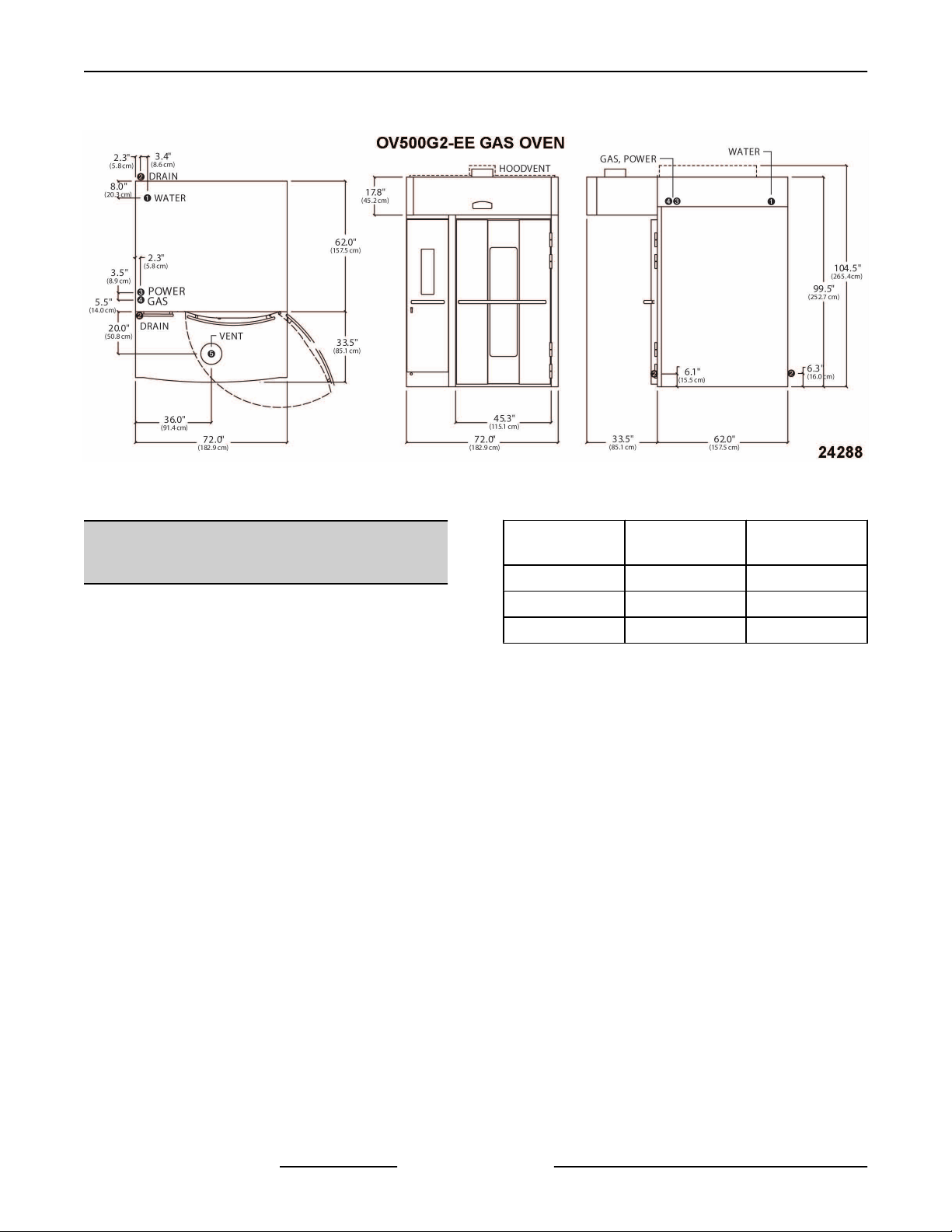
OV500G2-EE GAS OVEN
SPECIFICATIONS
1. WATER:
1/2" NPT, 30-75 PSI cold water required,
customer
line strainer.
2. DRAIN:
2 3/4" (front) or 5 1/2" (rear) connection A.F.F.
SEE NOTES. Route to air-gap drain. Do not
slope drain upwards. Plug the drain connection
that is not in use. Kit provided to extend drain to
either side of oven.
Rear Drain: 3/4" NPTF
Front Drain: 3/8" NPTF
3. POWER:
Two supplies required.
120/60/1 20 AMP dedicated circuit required and
one of the following voltage options.
208 - 240/60/1 8.8 - 7.6 AMPS
208-240/60/3 5.0 - 4.4 AMPS
440 - 480/60/3 2.4 - 2.2 AMPS
4. GAS:
Natural Gas (N.G.)
1/4" NPT, W.C.N.G. (N.G. rated 1025 BTU/CU.
1
FT. SP. GR. 1.00)
Liquified Propane Gas (L.P.G.)
1/4" NPT, W.C.L.P.G. (L.P.G. rated 2440 BTU/
1
CU.FT., SP. GR. 1.52)
BTU/HR 275,000 275,000
INLET
PRESSURE
MANIFOLD
PRESSURE
5. HOOD VENT:
10" DIA connection collar. Air proving switch
factory
operation. Oven provided rely with max. 10 amp
1/2 H.P. @ 120V output for fan operation. If
larger, use oven relay to control additional
separately powered contactor / relay for hood
to install in-line filter, shut off valve and
Voltage Full Load AMPS
Natural Gas
5.0 -10.0" W.C.
3.5" W.C. 8.75" W.C.
installed & integrated with burner system
Liquified
Propane Gas
10.0" - 14.0"
W.C.
fan. Customer to supply duct and ventilator fan
per state and local codes. Chamber vents are
factory ducted to this integral hood. 900 CFM
required, 0.6" W.C. static pressure drop through
hood. Hood is UL710 Listed when grease filters
are installed. Type B gas vent can be used except
when bake products are grease laden.
NOTES:
1. A.F.F.: Above finished floor.
2. Customer responsible to finish and install all
utilities to and from oven.
3. All services must comply with all Federal, State
and Local codes.
To reduce the risk of fire, the appliance is
to be installed on non-combustible surface only, with
no combustible material within 18 inches above the
appliance. The appliance is to be mounted on floors
of non-combustible construction with non-combustible
flooring and surface finish and with no combustible
material against the underside, or on non-combustible
slabs or arches having no combustible material
against the underside. Such construction shall in all
cases extend not less than 12 inches beyond the
equipment on all sides.
4. The floor must be of non-combustible material,
and must be level with surrounding area with a
maximum slope of 1/8" per foot up to 3/4"
maximum in all directions. Floor anchors require
a minimum 1" thick solid floor substrate.
5. Oven is UL/C-UL classified and CSA (AGA/CGA)
approved for 0" clearance on the side and rear
walls. Unit requires 1" to 4" clearance for rear
drain connection.
6. Top of oven requires a minimum of 24" for service
accessibility.
7. Customer responsible to install flue piping. Flue
must be vented outside of building.
8. Manufacturer reserves the right to make changes
in sizes and specifications.
Export Ratings
1. WATER:
1/2” NPT, 2.1-5.2 Bar cold water required,
customer to install in-line filter, shut off valve and
line strainer. Flow rate of 8 l/min..
2. DRAIN:
F45469 Rev. D (1019) Page 10 of 49
Page 11
INSTALLATION INSTRUCTIONS OV500-EE SERIES GAS RACK OVENS AND OV500 SERIES ELECTRIC RACK
OVENS - GENERAL
2 3/4" (front) or 5 1/2" (rear) connection A.F.F.
Route to air-gap drain. Do not slope drain
upwards.
use. Kit provided to extend drain to either side of
oven.
Rear Drain: 3/4" NPTF
Front Drain: 3/8" NPTF
3. POWER:
Two supplies required. Control circut:
100/50/60/1 or 208-240/50/1
1 kVA transformer supplied for control circuit
operation voltage of 110V. This is a multifunction
transformer, so output voltage should be verified
before operation. Some wiring may be required
to obtain proper output voltage.
Oven fan (1.1kW) operates @ 200/50/60/3 amps
or 380-415/50/3, 2.8-2.5 amps
4. GAS:
Natural Gas (N.G.)
1/4” NPT (N.G. Rated 38.2Mj/m3 or 9120 Kcal/
1
m3 SP Gr 1.00)
Liquefied Propane Gas (LPG)
3/4” NPT (LPG Rated 90.9Mj/m3 or 21710 Kcal/
m3 SP Gr 1.52)
RATING 69,300 Kcal/hr 69,300 Kcal/hr
INLET
PRESSURE
Plug the drain connection that is not in
Natural Gas
12.7 - 25.4 cm
W.C.
Liquified
Propane Gas
30.5 - 35.6 cm
W.C.
Natural Gas
MANIFOLD
PRESSURE
RATING 290 Mj/hr 290 Mj/hr
INLET
PRESSURE
MANIFOLD
PRESSURE
NOTE: Pressure not to exceed 35.6 cm W.C. or 3.5
kPa
5. HOOD VENT:
25.4 cm DIA. Connection collar. Customer is to
supply duct and ventilator fan per federal and/or
local codes. Chamber vent (steam) and
combustion exhaust are discharged into the
hood. An air proving switch is factory installed
and integrated with burner system operation. If
proper ventilation is not provided, burner will not
operate. Oven provides a relay to activate a
customer
so that when oven is powered up external fan will
operate. The hood requires a minimum of 25.5
m3/min for safe operation. For fan calculation
purposes you should assume 0.15 kPa
resistance through the hood. Grease filters
(optional) may be installed in the hood instead of
standard baffle.
8.9 cm W.C. 22.22 cm W.C.
1.25 - 3.50 kPa 3.00 - 3.50 kPa
.87 kPa 2.18 kPa
supplied and powered contactor/relay,
Liquified
Propane Gas
Page 11 of 49 F45469 Rev. D (1019)
Page 12
INSTALLATION INSTRUCTIONS OV500-EE SERIES GAS RACK OVENS AND OV500 SERIES ELECTRIC RACK
OVENS - GENERAL
Fig. 3
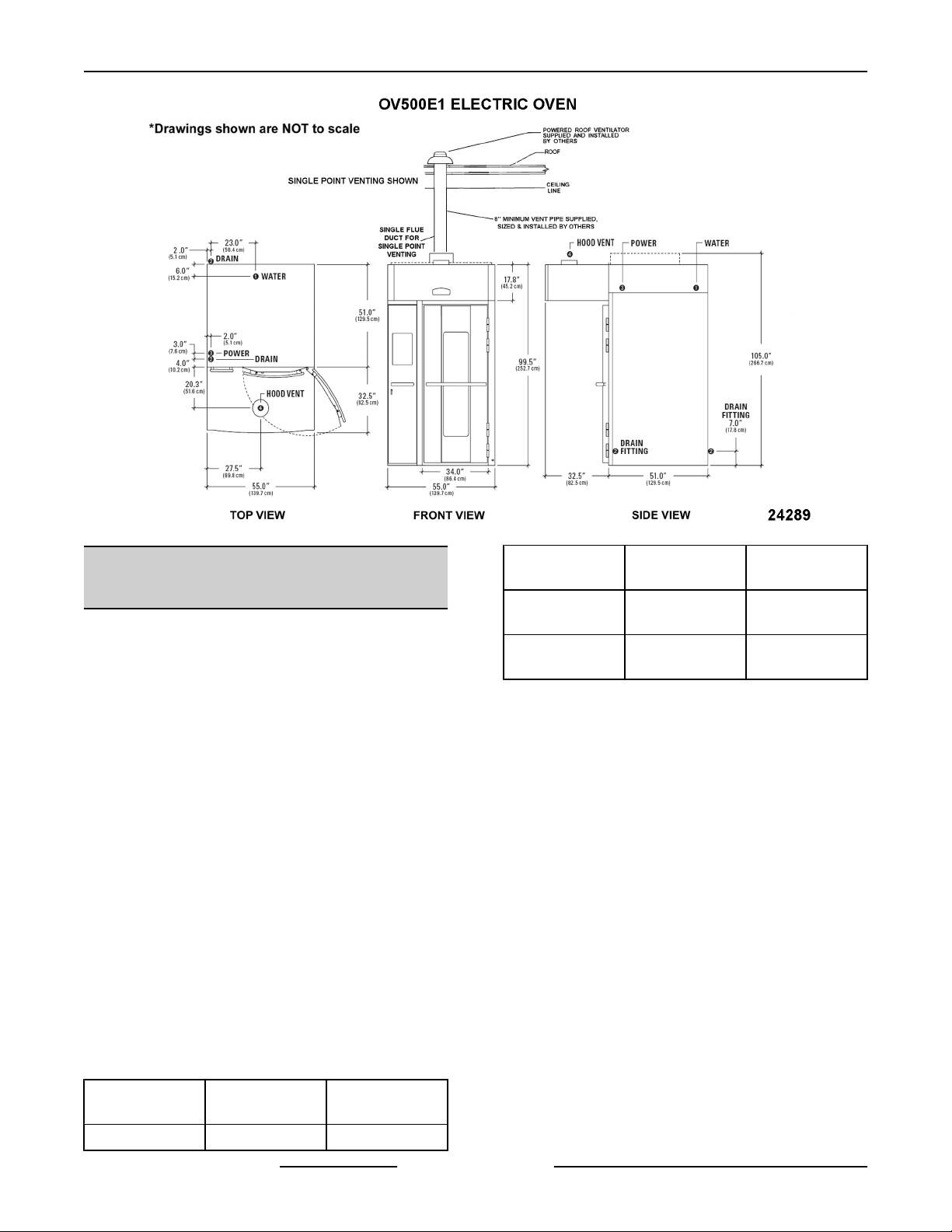
OV500E1 ELECTRIC OVEN
SPECIFICATIONS
1. WATER:
1/2" NPT, 30-75 PSI cold water required,
customer to install in-line filter, shut off valve and
line strainer.
2. DRAIN:
6 1/4" (front) or 7" (rear) connection A.F.F. .
Route to air-gap drain. Do not slope drain
upwards. Plug the drain connection that is not in
use.
Rear Drain: 1/2" NPTF
Front Drain: 1/2" NPTF
3. POWER:
Two supplies required.
120/60/1 20 AMP dedicated circuit required and
one of the following voltage options.
Heating Circuit: KW rating in following chart per
supply voltage.
Blower Motor: 1 1/2 H.P.
Voltage
208/60/3 100 AMPS 34 KW
208 - 240/60/3 76 - 87 AMPS 26 - 34 KW
440 - 480/60/3 40 - 43 AMPS 29 - 34 KW
4. HOOD VENT:
8" DIA connection collar. Customer to supply
duct and ventilator fan per state and local codes.
Oven provided relay with max. 10 amp 1/2 H.P.
@ 120V output for fan operation. If larger, use
oven relay to control additional separately
powered contactor / relay for hood fan. Chamber
vents are factory ducted to this integral hood. 690
CFM required, 0.6" W.C. static pressure drop
through hood. Hood is UL710 Listed when
grease filters are installed. Type B gas vent can
be used except when bake products are grease
laden.
NOTES:
1. A.F.F.: Above finished floor.
2. Customer responsible to finish and install all
utilities to and from oven.
3. All services must comply with all Federal, State
and Local codes.
Full Load
AMPS
Heaters Rating
F45469 Rev. D (1019) Page 12 of 49
Page 13

INSTALLATION INSTRUCTIONS OV500-EE SERIES GAS RACK OVENS AND OV500 SERIES ELECTRIC RACK
OVENS - GENERAL
To reduce the risk of fire, the appliance is
to be installed on non-combustible surface only, with
no combustible material within 18 inches above the
appliance. The appliance is to be mounted on floors
of non-combustible construction with noncombustible
flooring and surface finish and with no combustible
material against the underside, or on non-combustible
slabs or arches having no combustible material
against the underside. Such construction shall in all
cases extend not less than 12 inches beyond the
equipment on all sides.
4. The floor must be of non-combustible material,
and must be level with surrounding area with a
maximum slope of 1/8" per foot up to 3/4"
maximum in all directions. Floor anchors require
a minimum 1" thick solid floor substrate.
5. Oven is UL/C-UL classified and CSA (AGA/CGA)
approved for 0" clearance on the side and rear
walls. Unit requires 1" to 4" clearance for rear
drain connection.
6. Top of oven requires a minimum of 24" for service
accessibility.
7. Customer responsible to install flue piping. Flue
must be vented outside of building.
8. Manufacturer reserves the right to make changes
in sizes and specifications.
Export Ratings
1. WATER:
1/2” NPT, 2.1 - 5.2 Bar cold water required,
customer to install in-line filter, shut off valve and
line strainer. Flow rate of 8 l/min.
2. DRAIN:
N/A
3. POWER:
Two supplies required. 100V/50-60Hz/1Ph or
208-240V/50Hz/1Ph
⅛ kVA transformer supplied for control circuit
operation
transformer, so output voltage should be verified
before operation. Some wiring may be required
to obtain proper output voltage.
Oven fan (1.1kW) operates @ 200V/50-60Hz/
3Ph, 5.3 amps or 380-415V/3Ph/50Hz/ 2.4-2.2A
Voltage
200/50 - 60/3 74 AMPS 24 KW
380 - 415/50/3 46 - 50 AMPS 29 - 34 KW
4. HOOD VENT:
20.3 cm DIA. Connection collar. Customer is to
supply duct and ventilator fan per federal and/or
local codes. Chamber vent (steam) and
combustion exhaust are discharged into the
hood. Oven provides a relay to activate a
customer
so that when oven is powered up external fan will
operate. The hood requires a minimum of 19.5
m^3/min for safe operation. For fan calculation
purposes you should assume 0.15 kPa
resistance through the hood. Grease filters
(optional) may be installed in the hood instead of
standard baffle.
voltage of 110V. This is a multifunction
Full Load
AMPS
supplied and powered contactor/relay,
Heaters Rating
Page 13 of 49 F45469 Rev. D (1019)
Page 14
INSTALLATION INSTRUCTIONS OV500-EE SERIES GAS RACK OVENS AND OV500 SERIES ELECTRIC RACK
OVENS - GENERAL
OV500E2 ELECTRIC OVEN
SPECIFICATIONS
1. WATER:
1/2" NPT, 30-75 PSI cold water required,
customer
line strainer.
2. DRAIN:
2 3/4" (front) or 5 1/2" (rear) connection A.F.F. .
Route to air-gap drain. Do not slope drain
upwards. Plug the drain connection that is not in
use. Kit provided to extend drain to either side of
oven.
Rear Drain: 3/4" NPTF
Front Drain: 3/8" NPTF
3. POWER:
Two supplies required.
120/60/1 20 AMP dedicated circuit required and
one of the following voltage options.
Heating Circuit: KW rating in following chart per
supply voltage.
Blower Motor: 1 1/2 H.P.
Voltage
208/60/3 146.4 AMPS 51.3 KW
to install in-line filter, shut off valve and
Full Load
AMPS
Heaters Rating
Fig. 4
Voltage
208 - 240/60/3
440 - 480/60/3
4. HOOD VENT:
10"DIA connection collar. Customer to supply
duct
and ventilator fan per state and local codes.
Oven provided relay with max. 10 amp 1/2 H.P.
@ 120V output for fan operation. If larger, use
oven relay to control additional separately
powered contactor / relay for hood fan. Customer
to supply duct and ventilator fan per state and
local codes. Chamber vents are factory ducted to
this integral hood. 900 CFM required, 0.6" W.C.
static pressure drop through hood. Hood is
UL710 Listed when grease filters are installed.
Type B gas vent can be used except when bake
products are grease laden..
NOTES:
1. A.F.F.: Above finished floor.
2. Customer responsible to finish and install all
utilities to and from oven.
3. All services must comply with all Federal, State
and Local codes.
Full Load
AMPS
111.2 - 127.2
AMPS
59.1 - 64.1
AMPS
Heaters Rating
38.5 - 51.3 KW
43 - 51.3KW
F45469 Rev. D (1019) Page 14 of 49
Page 15
INSTALLATION INSTRUCTIONS OV500-EE SERIES GAS RACK OVENS AND OV500 SERIES ELECTRIC RACK
OVENS - GENERAL
To reduce the risk of fire, the appliance is
to be installed on non-combustible surface only, with
no combustible material within 18 inches above the
appliance. The appliance is to be mounted on floors
of non-combustible construction with noncombustible
flooring and surface finish and with no combustible
material against the underside, or on non-combustible
slabs or arches having no combustible material
against the underside. Such construction shall in all
cases extend not less than 12 inches beyond the
equipment on all sides.
4. The floor must be of non-combustible material,
and must be level with surrounding area with a
maximum slope of 1/8" per foot up to 3/4"
maximum in all directions. Floor anchors require
a minimum 1" thick solid floor substrate.
5. Oven is UL/C-UL classified and CSA (AGA/CGA)
approved for 0" clearance on the side and rear
walls. Unit requires 1" to 4" clearance for rear
drain connection.
6. Top of oven requires a minimum of 24" for service
accessibility.
7. Customer responsible to install flue piping. Flue
must be vented outside of building.
8. Manufacturer reserves the right to make changes
in sizes and specifications.
Export Ratings
1. WATER:
1/2” NPT, 2.1 - 5.2 Bar cold water required,
customer to install in-line filter, shut off valve and
line strainer. Flow rate of 8 l/min.
2. DRAIN:
N/A
3. POWER:
Two supplies required. 100V/50-60Hz/1Ph or
208-240V/50Hz/1Ph
⅛ kVA transformer supplied for control circuit
operation
transformer, so output voltage should be verified
before operation. Some wiring may be required
to obtain proper output voltage.
Oven fan (1.1kW) operates @ 200V/50-60Hz/
3Ph/5.3A or 380-415V 3ph 50 Hz 2.4- 2.2A
Voltage
200/50 - 60/3 108 AMPS 36 KW
380 - 415/50/3 68 - 73AMPS 43 - 51 KW
4. HOOD VENT:
25.4 cm DIA. Connection collar. Customer is to
supply duct and ventilator fan per federal and/or
local codes. Chamber vent (steam) and
combustion exhaust are discharged into the
hood. Oven provides a relay to activate a
customer
so that when oven is powered up external fan will
operate. The hood requires a minimum of 25.5
m3/min for safe operation. For fan calculation
purposes you should assume 0.15 kPa
resistance through the hood. Grease filters
(optional) may be installed in the hood instead of
standard baffle.
voltage of 110V. This is a multifunction
Full Load
AMPS
supplied and powered contactor/relay,
Heaters Rating
Page 15 of 49 F45469 Rev. D (1019)
Page 16

INSTALLATION INSTRUCTIONS OV500-EE SERIES GAS RACK OVENS AND OV500 SERIES ELECTRIC RACK
OVENS - GENERAL
Fig. 5
F45469 Rev. D (1019) Page 16 of 49
Page 17

INSTALLATION INSTRUCTIONS OV500-EE SERIES GAS RACK OVENS AND OV500 SERIES ELECTRIC RACK
OVENS - INSTALLING OVEN
INSTALLING OVEN
manual is written for a new installation where you can position the oven sections while the oven is on the shipping
This
skids. Some installations may require that oven sections on the skids be lifted on there side and manipulated through
doorways prior to positioning sections for installation.
Prior to installing the oven, check facilities floor for being level within a maximum of 1/8" per foot up to 3/4" in all
directions using the laser level technique to determine if oven will need to be shimmed. Also check facilities floor
area at the threshold and door swing opening location to determine if facilities floor will need to be reworked.
OVEN SECTIONS
Remove all assemblies except oven sections from
skids prior to lifting oven sections. In some cases
OV500G1-EE
sections assembled together.
NOTE: On split OV500 single rack ovens, remove the
rack lift/rotate assembly and center insulation cover
from the top of the oven prior to standing up.
1. Place the oven sections as close to the final
position as possible, allowing enough room to
work, with the sections positioned for lifting.
& OV500E1 ovens will be shipped with
A. Check for ceiling clearance. The oven is
tallest when it is approximately 60 degrees
to the floor during the raising process. If
oven section has been turned on its narrow
side in order to navigate through a doorway,
turn the oven section back to the shipping
position prior to raising.
B. Remove the bottom hold down brackets
from both pallets, but do not remove oven
sections from pallets.
DO NOT remove the two top
brackets prior to lifting units.
2. Lift the oven sections upright, using the hoist
technique. Both oven sections should be as close
as possible, but not touching.
NOTE: Single rack ovens have a one piece floor. The
floor will need to be put into location with a bead of red
high temp silicone around the outer edge of floor
flange before oven sections are slid together. The right
front corner of oven will need to be lifted, to clear
flange on the floor (door jamb retainer) when installing
a one piece floor.
Fig. 6
Fig. 7
Page 17 of 49 F45469 Rev. D (1019)
Page 18

INSTALLATION INSTRUCTIONS OV500-EE SERIES GAS RACK OVENS AND OV500 SERIES ELECTRIC RACK
OVENS - INSTALLING OVEN
Fig. 8
3. Once the oven is in the upright position, remove
the top two brackets securing the oven to the
skid.
B. Lower the skid to the floor making sure that
the Z channel does not scratch the oven
side.
C. Perform the same procedure for other oven
section.
Fig. 10
Fig. 9
The z bracket location on the bottom
of the skid must be disengaged before lowering the
skid. If engaged when lowering the skid, the oven
section could fall.
4. Remove the header support bracket.
A. Remove the two screws from hinge side of
bracket.
B. Move bracket and reinstall the hinge
screws.
C. Remove the single screw from the header
side of bracket and discard screw and
bracket.
A.
Pull the bottom of the skid away from the
oven to clear the Z channel.
5.
F45469 Rev. D (1019) Page 18 of 49
Fig. 11
Slide the oven sections together.
Page 19

INSTALLATION INSTRUCTIONS OV500-EE SERIES GAS RACK OVENS AND OV500 SERIES ELECTRIC RACK
OVENS - INSTALLING OVEN
NOTE: Caulk inner seam before placing halves
together.
Fig. 12
NOTE: Ensure ceiling offset flange slides under
opposite oven section ceiling.
Fig. 13
6. Install ½-13
in rear frame connection points of oven, both top
and bottom.
x 1-1/2" bolt with lock washer and nut
Fig. 15
NOTE: If you have trouble aligning the holes in the
rear frame, you may have to manipulate the oven
sections using the levelers, using shims, or by prying.
Use care not to damage building floor.
Fig. 16
Fig. 14
7. Install 5/16-18
header connections.
NOTE: Ensure oven sections upper header front
surfaces are flush.
x 1" gimlet screws in upper & lower
Page 19 of 49 F45469 Rev. D (1019)
Page 20

INSTALLATION INSTRUCTIONS
NOTE: You may have to move oven front corners to
make the holes in the outer header align with the holes
in the oven.
Fig. 17
8. Install 5/16-18 X1" gimlet screws in the flanges
of the mating sections around the oven
perimeter, both top and back.
OV500-EE SERIES GAS RACK OVENS AND OV500 SERIES ELECTRIC RACK
OVENS - INSTALLING OVEN
Fig. 19
10. For OV500G1-EE & OV500E1 ovens only: Install
insulation cover onto top of oven.
11. For OV500G1-EE & OV500E1 ovens only: Install
rotator assembly onto lifter assembly.
NOTE: Start a few screws at several locations around
the flange to help align the flange holes.
9. Install all flange mating section screws and
insure mating surfaces are flush in the interior &
exterior of the oven before tightening the screws.
NOTE: If you have trouble aligning the mating holes
in the flange, you may have to manipulate the oven
sections using the levelers or by prying.
Fig. 20
12. Install upper header support plate with #10 Tek
screws.
Fig. 18
F45469 Rev. D (1019) Page 20 of 49
Page 21

INSTALLATION INSTRUCTIONS OV500-EE SERIES GAS RACK OVENS AND OV500 SERIES ELECTRIC RACK
OVENS - INSTALLING OVEN
Fig. 21
13. Install lower header cover with two 10-32 screws
lose to hold cover in place.
Fig. 22
14. Install
upper header cover with #10 X 3/4" screws
on top and 1/4-20 screws on the bottom with front
edge of cover flush with door jambs.
Fig. 24
A. Cut off gasket material to length of retainer.
B. Install upper door gasket & upper gasket
retainer by removing the two lower header
cover screws then secure gasket & retainer
to cover with 10-32 gimlet screws.
Fig. 25
16.
Install 1/4-20 X 3/4" hex head serrated flange
screws onto ceiling offset inside baking
compartment.
Fig. 23
15.
Install upper door gasket to upper gasket
retainer.
Fig. 26
17.
Install insulation pieces.
NOTE: Before installing rear panel on double rack
ovens, tighten the drain line union fitting.
Page 21 of 49 F45469 Rev. D (1019)
Page 22

INSTALLATION
A. On the rear seam, bend the copper studs so
they
installing the insulation, make sure the
insulation is held by these studs.
INSTRUCTIONS OV500-EE SERIES GAS RACK OVENS AND OV500 SERIES ELECTRIC RACK
are 90 degrees to the oven wall. When
Fig. 27
OVENS - INSTALLING OVEN
B. At the rear wall, place the push nuts over the
copper studs to secure the insulation.
Fig. 29
B. Push the panel up until the bottom of the
panel clears the bottom rail of the oven
section frame.
Fig. 28
18. Install rear cover panel.
NOTE:
F45469 Rev. D (1019) Page 22 of 49
This panel will also have a layer of insulation.
A. Start the top of the panel behind the top rail
of the upper frame.
Fig. 30
C. Make sure that the panel is behind the rail
of the lower frame and will rest against the
stop when lowered into position.
Page 23

INSTALLATION INSTRUCTIONS OV500-EE SERIES GAS RACK OVENS AND OV500 SERIES ELECTRIC RACK
OVENS - INSTALLING OVEN
D. Push the panel down against the stop.
Fig. 33
Fig. 31
19. Connect rear drain if required.
A. Using materials from provided drain kit
(double rack ovens only), route the drain to
either side of oven.
B. Ensure drain slopes downward 1/4"per ft.
20. For OV500G2-EE & OV500E2 ovens only: Install
insulation into ceiling channel.
22. Remove junction box cover to access connection
plugs for rack rotation and rack lift. Connect plugs
together and install raceway to top of oven.
NOTE: Gas ovens will not have junction box, but
conduit directly to component. Electric double rack
ovens will have an additional cover (1, Fig. 36) to be
installed over exposed wiring (2, Fig. 36).
Fig. 32
21. For OV500G2-EE & OV500E2 ovens only: Install
ceiling channel cover with #10 Tek screws over
the ceiling channel.
Page 23 of 49 F45469 Rev. D (1019)
GAS OVENS
SINGLE ELECTRIC OVENS
Page 24

INSTALLATION INSTRUCTIONS OV500-EE SERIES GAS RACK OVENS AND OV500 SERIES ELECTRIC RACK
OVENS - INSTALLING OVEN
Fig. 36
23. If
rear drain of oven is used install before oven is
placed in final location.
24. Remove protective plastic from rear and sides of
the oven that won't be accessible once the oven
is in place.
NOTE: Do not damage building floor while installing
dolly wheel or using front levelers. Use shims under
floor levelers to prevent damage to building floor.
B. Lower the rear wheels to raise the back of
the oven from touching the floor.
Fig. 38
25. Install the dolly wheel.
Fig. 37
NOTE:
the front of the oven to install the dolly wheel. Use care
not to damage building floor.
You may have to use the front levelers to raise
A. Raise the front oven levelers so the weight
of the oven is on the dolly wheel.
Fig. 39
NOTE: Raising the rear of the oven too much can
cause the front of the oven to contact the floor.
26.
Move the oven into the final position before
lowering.
27. Place shim(s) per the height determined by the
laser level technique to level oven.
NOTE: Review HOST course for laser level
technique.
NOTE: After oven is leveled and shimmed, raise the
levelers to take the oven weight off all the levelers.
F45469 Rev. D (1019) Page 24 of 49
Page 25

INSTALLATION INSTRUCTIONS OV500-EE SERIES GAS RACK OVENS AND OV500 SERIES ELECTRIC RACK
OVENS - INSTALLING OVEN
Fig. 42
C. If diagonal measurements are not within
1/8" of each other add additional shims as
needed.
1) If diagonal 'Y' measurement is greater
than diagonal 'X' measurement add
Fig. 40
28. Raise the back wheels to lower the oven. Weight
of oven should be completely off back wheels.
shims under the right front door jamb.
Place shims on top of threshold
underneath the door jamb.
29. Remove the dolly wheel and replace lower latch
ramp.
NOTE: Retain the dolly wheel for future oven
installations.
30. Place threshold into door jamb.
NOTE: Do not anchor threshold at this time.
31. Verify door opening is square.
A. Measure diagonal 'X' from top right
innermost hinge screw to the bottom
innermost hinge screw on the left door jamb.
Fig. 43
2) If diagonal 'X' measurement is greater
than diagonal 'Y' measurement add
shims under the left front door jamb.
Fig. 41
B. Measure diagonal 'Y' from the top left
innermost hinge screw to the bottom
innermost hinge screw on the right door
jamb.
Fig. 44
Page 25 of 49 F45469 Rev. D (1019)
Page 26

INSTALLATION INSTRUCTIONS OV500-EE SERIES GAS RACK OVENS AND OV500 SERIES ELECTRIC RACK
OVENS - INSTALLING OVEN
D. Repeat procedure until diagonal
measurements are within 1/8" of each other.
NOTE: If shims are required to level the oven at the
front right corner, shims(s) will need to be placed on
top of threshold underneath the door jamb.
NOTE: If shims are required to level the oven at the
rear corners, place shim(s) in front of the back wheels.
If the rear of the oven is not accessible, place shims
under heat exchanger floor and inner wall base angle.
32. Install the door.
A. Open glass compartment door to remove
door handle and set aside.
NOTE: Tab for opening to gain access to
compartment.
Fig. 45
B. Close glass compartment door.
NOTE: Do not allow glass compartment door to slam
shut.
C. Position the door at 90 degrees to the oven
near the door opening.
D. Use a J bar to lift the door close to the hinge
side of the door.
NOTE: Use care not to place J bar under black glass
door hinge pin or the door glass.
E. Position the door over the hinges and then
lower onto the hinge pins.
33. With the door open, visually check if door swings
towards oven (closed position) on its own.
A. If door swings towards oven, add shims to
back corners of oven until door stops
swinging on its own.
34. Remove bolts securing steam panel to oven.
F45469 Rev. D (1019) Page 26 of 49
Page 27

INSTALLATION INSTRUCTIONS OV500-EE SERIES GAS RACK OVENS AND OV500 SERIES ELECTRIC RACK
OVENS - INSTALLING OVEN
A. Lift panel up while tilting top of panel
towards center of oven to remove from
oven.
Fig. 48
37. Install drain pan cover.
FLOOR / THRESHOLD
1. Move threshold halfway out from oven.
Fig. 46
35. Remove screws securing drain pan cover to
oven.
A. Pull cover out from suction panel while lifting
up right side of cover then pushing cover
towards the right rear corner of baking
compartment and out from oven.
NOTE: Use care when removing cover not to scratch
baking compartment walls.
2. Caulk around baking compartment to facility floor
seam with red RTV silicone.
NOTE: The sealant used inside the oven cavity must
be NSF Listed; suitable for food zone and minimum
275ºC/525ºF. The sealant used on the exterior of the
unit must be NSF Listed.
Fig. 47
36.
Lower drain pan support bolt until bolt comes in
contact with the floor.
NOTE: Bolt used to support steam system weight.
Fig. 49
3.
Run a bead of red RTV silicone on the entire
outer edge of both floor panels.
4. Install floor panel without offset. Flange goes up.
Page 27 of 49 F45469 Rev. D (1019)
Page 28

INSTALLATION INSTRUCTIONS OV500-EE SERIES GAS RACK OVENS AND OV500 SERIES ELECTRIC RACK
OVENS - INSTALLING OVEN
5. Run
NOTE: Double Rack only.
6. Install floor panel without offset. Flange goes up.
7. Run two beads of red RTV silicone on the flange
8. After the Oven has been Leveled and shimmed .
two beads of red RTV silicone on the flange
of floor panel without offset.
of floor panel without offset.
Attach the floor trim to the inner wall.
Fig. 52
Slide threshold under door jamb. Ensuring the
10.
three threshold tabs are installed over the oven
floor.
NOTE: Use a hammer and 2X4 to tap threshold
against oven floor. A 1/8" gap between oven floor and
threshold is acceptable.
NOTE: If shims were required to level oven and
square the door jamb at the front right corner, place
shims(s) on top of threshold underneath the door
jamb. Threshold is approximately one shim thick.
Fig. 50
9. After oven is leveled and shimmed, remove
screws and washers holding the floor in place.
NOTE: Single Whole Ovens only.
Fig. 51
Fig. 53
11. Use
NOTE: Left side, Rear wall, and Right side flanges
need to be silicone.
12. Install floor trim. Wait until later in the procedure
13. Drill & tap into door jamb at threshold clearance
Red NSF listed silicone to seal the top edge
of the floors flange, prior to installing floor trim.
to tighten screws.
holes.
F45469 Rev. D (1019) Page 28 of 49
A. Secure threshold to door jamb with 10-32 X
1/2" screws, secure left side first.
Page 29

INSTALLATION INSTRUCTIONS OV500-EE SERIES GAS RACK OVENS AND OV500 SERIES ELECTRIC RACK
OVENS - INSTALLING OVEN
17. Caulk door jamb gaps with gray NSF listed
silicone.
Fig. 54
14. Anchor threshold to facility floor.
Fig. 57
STEAM SYSTEM
Fig. 55
15.
Tighten floor trim screws.
16. Caulk gap between oven floor and threshold with
gray NSF listed silicone.
1. Remove top & left air guides from oven wall.
2. Run a bead of red NSF listed silicone between
drain pan and rear oven wall.
Fig. 58
NOTE: Fig. 58 shows Double Rack Oven.
3.
Start by setting the first steam ball assembly flat
on the oven baking compartment floor (left rear
corner).
NOTE: For OV500G1-EE & OV500E1 ovens, place
first steam ball assembly on spacers to obtain correct
height.
Fig. 56
Page 29 of 49 F45469 Rev. D (1019)
Page 30

INSTALLATION INSTRUCTIONS OV500-EE SERIES GAS RACK OVENS AND OV500 SERIES ELECTRIC RACK
OVENS - INSTALLING OVEN
Fig. 59
NOTE: Fig. 59 shows Single Rack Oven.
NOTE:
are not oriented correctly.
6. Before last couple sets of assemblies are
The assemblies will not set level if the sections
Fig. 62
installed, slide spray guard onto manifold. Align
manifold with steam ball assemblies. Allow spray
guard to hang on manifold.
Fig. 60
4.
(Only on ovens with 38 castings) Install splash
panel with angled ledge on top of first steam ball
assembly and the baffle supported by the back
wall .
Fig. 61
5.
The next steam ball assembly must be put in
place matching the female post with male post of
previous assembly (total of 30 or 38 sections for
OV500G2-EE & OV500E2 ovens, total of 15
sections for OV500E1, and total of 20 sections
for OV500G1-EE ovens to install).
Fig. 63
7.
After all assemblies are installed, place spray
guard on last set of steam balls & install water
guides to edge of assemblies.
8. Begin with the top assembly and install water
guides over front rim of the top, then every other
assembly (total of 7 water guides for all ovens.
F45469 Rev. D (1019) Page 30 of 49
Page 31

INSTALLATION INSTRUCTIONS OV500-EE SERIES GAS RACK OVENS AND OV500 SERIES ELECTRIC RACK
OVENS - INSTALLING OVEN
Fig. 64
9. Install both corner air guides.
Fig. 66
11. Install left baking compartment panel.
12. Align steam panel with screw inserts in baking
compartment ceiling (left rear corner) and loosely
secure panel to ceiling with 1/4-20 X 3/4" hex
head serrated flange screws.
Fig. 65
10.
Position spray guard to rest on top of steam ball
assemblies.
OVEN
OV500G2EE 30 PSC
OV500G1EE 20 PCS
OV500E2 30 PSC
OV500E1 15 PCS
NOTE: For SEF ovens, pieces may very.
NUMBER OF PIECES
Fig. 67
13. Secure
panel with 1/4-20 X 3/4" hex head serrated flange
screws.
Page 31 of 49 F45469 Rev. D (1019)
steam panel to rear baking compartment
Fig. 68
Page 32

INSTALLATION INSTRUCTIONS OV500-EE SERIES GAS RACK OVENS AND OV500 SERIES ELECTRIC RACK
OVENS - INSTALLING OVEN
14. Secure steam panel to left baking compartment
with 1/4-20 X 3/4" hex head serrated flange
panel
screws.
Fig. 69
15. Tighten screws at top of steam panel.
DOOR HANDLE
1. Remove pivot screw from door handle pivot
bracket on door assembly.
NOTE: Ensure lock mechanism is in the unlocked
position.
Fig. 72
Fig. 70
2.
Install door handle onto pivot bracket and insert
screw removed earlier.
Fig. 73
DOOR ASSEMBLY
1. Observe the following:
A.
With the door closed, visually check gap
around door jamb and edge of door, gap
should be equal on both sides.
Fig. 71
A.
Push door handle locking end onto door
handle locking mount until handle locks onto
mount.
F45469 Rev. D (1019) Page 32 of 49
Page 33

INSTALLATION INSTRUCTIONS OV500-EE SERIES GAS RACK OVENS AND OV500 SERIES ELECTRIC RACK
OVENS - INSTALLING OVEN
B. If paper is loose, door latches will need
adjusted.
NOTE: Latch
door rollers with latch ramps during installation. This
should be done after loading door is installed and oven
is level.
3. To align door latches:
A. With both door latch ramps having gauge
NOTE: Vertical lines for adjusting the ramps so the
wheels hit at the same time.
NOTE: If necessary, Horizontal lines to help select
which latch arms to use for correct positioning of the
wheels.
alignment instructions are to help align
installed.
Fig. 74
NOTE: If the door rubs against the jamb or drags the
facility floor when opening, verify oven for levelness.
If leveling does not correct the problem then call
Bakery Service Support.
B. Adjust door hinge inward or outward until
door has an air tight seal against door
gasket.
Fig. 75
Fig. 76
B. Close the loading door to check roller shaft
alignment with latch ramp gauge. The roller
shaft should fit inside cutout on gauge as
shown.
2.
Verify door latches properly.
A. Insert a piece of paper between door jamb
and door gasket on both sides & top of door.
Fig. 77
C. If
roller shaft does not align with gauge, then
the latch arms will have to be replaced.
Page 33 of 49 F45469 Rev. D (1019)
Page 34

INSTALLATION INSTRUCTIONS OV500-EE SERIES GAS RACK OVENS AND OV500 SERIES ELECTRIC RACK
OVENS - INSTALLING OVEN
NOTE: The horizontal line closest to bottom of roller
shaft will determine which latch arm to use. The
horizontal lines and latch arms are identified with a
different number of holes. Diagram below shows you
would need
two oo’s.
to replace latch arms using latch arms with
Fig. 78
A.
Place a piece of paper at bottom hinge side
between door and door gasket.
Close oven door and slowly pull on paper.
B.
There should be just enough drag to hold
paper from falling. Repeat this procedure
around door every couple of feet. If door is
too tight on hinge side, loosen the hinges on
the door and adjust door outward, reverse if
to loose. For latch side adjustment, loosen
screws on ramp(s) and move ramp(s) in or
out.
C. After adjusting the ramps for proper gasket
seal, make sure rollers contact ramps at the
same time. To check this, push the door
closed until one roller lightly touches a ramp,
check to see where door edge aligns with
vertical lines on the ramp gauge. The door
edge should align with the same vertical line
on each ramp gauge.
4. To install latch arms:
A. Remove inner door handle cover.
B. Remove 3/8” bolt. DO NOT discard the tube,
bolt or washer.
C. Remove E-clip and pin. DO NOT discard the
E-clip or Pin.
D. Replace two latch arms with parts supplied.
Reassemble inner mechanism, making sure
linkage arms are located in the up position.
Re-attach inner door handle.
NOTE: For left hand hinge, bolt and arms must be
flipped and mounted to hole. place unused arms to
latch box and secure with 1/4-20 bolt.
Fig. 80
D. If adjustment is required, move a ramp so
that both rollers contact the ramps at the
same time.
NOTE: Keep in mind the door gasket seal. Both
ramps need to be in correct location to equalize
pressure on rollers.
6. Repeat the process until desired results are
obtained or call Bakery Product Support.
7. After desired results obtained, bend alignment
gauges back & forth to break off and discard.
Fig. 79
5. To adjust door gasket seal:
F45469 Rev. D (1019) Page 34 of 49
Page 35

INSTALLATION INSTRUCTIONS
OV500-EE SERIES GAS RACK OVENS AND OV500 SERIES ELECTRIC RACK
OVENS - INSTALLING OVEN
DOOR SWITCH ACTUATOR
1. Check door switch actuator for proper operation
and adjust switch as needed.
Fig. 81
Fig. 83
DOOR SWEEP
1. Install door sweep.
NOTE: Door sweep shipped with door assembly.
A. Adjust the door sweep so the metal door
seal plate is 5/16" from the highest point on
the floor.
NOTE: Door sweep has slots for adjustment.
Fig. 82
Fig. 84
RACK CARRIER - A & C STYLE
RACK LIFT
NOTE: After oven has been leveled.
1. Remove snap ring (C lift) or pin and washer (A
lift) from rotation shaft and save for carrier
installation. Cardboard tube can be discarded.
Page 35 of 49 F45469 Rev. D (1019)
Page 36

INSTALLATION INSTRUCTIONS OV500-EE SERIES GAS RACK OVENS AND OV500 SERIES ELECTRIC RACK
OVENS - INSTALLING OVEN
Fig. 85
Installing "A" Lift (1.25" shaft)
A. Position carrier on shaft with arrows on the
shaft and carrier aligned.
B. Insert ½” pin through holes in carrier hub
and shaft.
NOTE: Pin should be centered and fit snug in shaft.
Fig. 86
C. Install
cover plate to the bottom of the carrier
with screws provided.
Fig. 88
C. Slide the carrier onto the lift mechanism
shaft and install the snap ring.
NOTE: Do Not allow the lift mechanism shaft to move
upward. Hold shaft down from top of oven.
2. Roll baking rack onto carrier and check for proper
carrier height.
NOTE: Carrier should be approximately 0.125" to
0.25" from rack lifting channels. Check multiple baking
racks.
Fig. 87
Installing "C" Lift (1.25" shaft)
A.
Install rack carrier.
B. Apply food grade Never Seize to set screw
threads on (C lift) and start the set screws
into the carrier.
F45469 Rev. D (1019) Page 36 of 49
Fig. 89
Fig. 90
Page 37

INSTALLATION INSTRUCTIONS OV500-EE SERIES GAS RACK OVENS AND OV500 SERIES ELECTRIC RACK
OVENS - INSTALLING OVEN
A. If carrier height needs adjusted, remove
baking
ladder and blocks of wood to correct height.
rack and support carrier with i.e. step
Fig. 93
E. Factory Installed shim washers 5 above & 5
below retaining ring. Position shim washers
above or below the retaining ring for correct
carrier height.
Fig. 91
B. Access rotate/lift assembly at top of oven.
C. Loosen rotate/lift shaft collar set screw 1/4
turn.
Fig. 92
D.
Remove screws securing Teflon bearing
bracket to rotate/lift assembly and lift from
assembly.
Fig. 94
F.
If carrier needs to be lower than snap ring
will allow, access clevis pins on rear of lift
and lower both equally.
NOTE: Always lower left and right clevis pins the
same distance. One hole location equals 1/4"
adjustment.
Page 37 of 49 F45469 Rev. D (1019)
Page 38

INSTALLATION INSTRUCTIONS OV500-EE SERIES GAS RACK OVENS AND OV500 SERIES ELECTRIC RACK
OVENS - INSTALLING OVEN
RACK CARRIER - B STYLE RACK
LIFT
NOTE: After oven is leveled.
Remove snap ring, shim washers, & card board
1.
shipping tube from lift shaft.
Fig. 95
3. Install snap ring, teflon plate and tighten set
screw.
NOTE: You made need to lift up on rotator body while
tightening set screw to get shims flush with the snap
ring.
NOTE: Check multiple racks.
Fig. 96
4.
Remove shipping ties from vent lid.
Fig. 98
2. Install rack carrier.
3. Apply food grade Never Seize to set screw
threads and start the set screws into the carrier.
Fig. 99
4. Slide
5. Roll baking rack onto carrier and check for proper
NOTE: Carrier should be approximately 0.125" to
0.25" from rack lifting channels. Check multiple baking
racks.
the carrier onto the lift mechanism shaft and
install snap ring.
carrier height.
Fig. 97
F45469 Rev. D (1019) Page 38 of 49
Page 39

INSTALLATION INSTRUCTIONS OV500-EE SERIES GAS RACK OVENS AND OV500 SERIES ELECTRIC RACK
OVENS - INSTALLING OVEN
Fig. 102
7. Snug the set screws to hold the carrier in place.
Fig. 100
A. Access rotate/lift assembly at top of oven.
B. If carrier needs to be lower than snap ring
will allow, access clevis pins and lower
location to correct carrier height.
NOTE: Always lower left and right clevis pins the
same distance. One hole location equals 1/4"
adjustment.
Fig. 101
6.
If the carrier needs to be adjusted to get proper
spacing, remove rack and add shims between
snap ring and carrier as shown. Ten shims are
provided with each oven.
8. Remove shipping ties from vent lid.
Fig. 103
HOOD ASSEMBLY
NOTE: After the hood is installed the door assembly
can
not be lifted off the hinge pins. The door assembly
would have to be removed & installed from the door
hinges.
1. Set hood on the floor in front of oven (if hood
supplied). Remove only the necessary protective
plastic from the hood.
NOTE: Check multiple racks
A. Attach side panels with 10-32 screws 10
screw holes to the back of the hood, and
ensure that the 3 screw holes are to the rear
on each side panel. Align top of hood up with
the top edge of side trim panels before
tightening the screws.
Page 39 of 49 F45469 Rev. D (1019)
Page 40

INSTALLATION INSTRUCTIONS OV500-EE SERIES GAS RACK OVENS AND OV500 SERIES ELECTRIC RACK
OVENS - INSTALLING OVEN
Fig. 104
Fig. 107
E. Ensure hood support bracket sets on front
top edge of oven.
F. Ensure bottom edge of hood is aligned with
bottom edge of oven support.
Fig. 105
B.
Attach rear panel to each side panel with
10-32 X 3/4" screws.
NOTE: If clearance is a problem, don't install the rear
panel, set hood with side panels in place first.
C. Apply gray NSF listed silicone around face
of overpressure duct.
Fig. 106
D.
Set hood in place on top of oven.
Fig. 108
G. Secure
top of oven.
H. If not attached in previous steps, attach rear
panel of hood.
I. Secure hood support bracket to top of oven
with #10 Tek screws.
side panels with #10 Tek screws into
F45469 Rev. D (1019) Page 40 of 49
Page 41

INSTALLATION INSTRUCTIONS OV500-EE SERIES GAS RACK OVENS AND OV500 SERIES ELECTRIC RACK
OVENS - INSTALLING OVEN
Fig. 111
4. Install over pressure damper to over pressure
vent (right side of hood) using #10 Tek screws.
Fig. 109
2. Remove perforated air baffle from hood.
Fig. 110
3.
Connect the over pressure vent (Right side of
hood) using #10 Tek screws 8 places total.
Fig. 112
5. Caulk
header and seams at hood and side panels
also bottom edge seam of hood along oven front
with gray silicone.
Fig. 113
Page 41 of 49 F45469 Rev. D (1019)
Page 42

INSTALLATION INSTRUCTIONS OV500-EE SERIES GAS RACK OVENS AND OV500 SERIES ELECTRIC RACK
OVENS - INSTALLING OVEN
Fig. 114
6. Customer is responsible for having a flue pipe
connected to the center hood connection. See
appropriate oven specification.
Fig. 117
Fig. 115
7.
Install bracket between top of hood and hood
side trim (2 places).
Fig. 116
HOOD VENTING
1. Install exhaust connection plate to hood
assembly.
NOTE: Electric
plate to close off exhaust opening in hood.
oven install a hood exhaust inclosure
Fig. 118
2.
Insert exhaust duct thru hood and connect to
draft inducer.
Fig. 119
F45469 Rev. D (1019) Page 42 of 49
Page 43

INSTALLATION INSTRUCTIONS OV500-EE SERIES GAS RACK OVENS AND OV500 SERIES ELECTRIC RACK
OVENS - INSTALLING OVEN
Fig. 120
3. Secure exhaust duct to exhaust connection
plate.
4. Secure exhaust duct with #10 Tek screws to draft
inducer.
Fig. 122
Fig. 121
5. Connect
pressure switch. Switch location on side of
control panel inside control compartment. Leave
tubing coiled in control compartment.
NOTE: Defer connecting hood vent tube to the
exhaust connection until start up.
the hood exhaust tube at hood exhaust
AIR BAFFLE & GREASE FILTERS
1. Install perforated air baffle with 1/4-20 acorn
nuts.
2. Install grease filters for type 1 hood or install
perforated plenum panel for type 2 hood.
hood
Fig. 123
Page 43 of 49 F45469 Rev. D (1019)
Page 44

INSTALLATION INSTRUCTIONS OV500-EE SERIES GAS RACK OVENS AND OV500 SERIES ELECTRIC RACK
OVENS - INSTALLING OVEN
• Gas supplied matches data plate and gas
valve on oven.
Gas valve is in the OFF position.
•
• Electrical connections have been made by
electrician. 120V control, high voltage, and
powered roof ventilator (external device).
NOTE: Refer to the service entrance label on the
oven for electrical connections.
• Turn the 120V supply power ON.
• Turn the circuit breakers ON.
• Drain connected (with air gap) by plumber
and opposite end of drain plugged.
Fig. 124
CAULK OVEN
• Water line is connect by plumber to flow
restrictor located on top left rear corner of
oven.
1. Caulk around oven with gray NSF listed silicone.
Fig. 125
INITIAL START-UP
Disconnect the
electrical power to the machine and
follow lockout / tagout procedures.
There
may be multiple circuits. Be sure
all circuits are disconnected.
• Water shut off is installed in supply line.
NOTE: If a water filtration unit is installed in supply
line, verify that a filter cartridge is installed in unit
(performed by customer).
NOTE: Refer to oven installation checklist and
complete during initial start-up.
Start Up
1. Connect hood exhaust pressure switch tubing to
hood exhaust connection.
NOTE: Make sure that there is a point in the tubing
that is higher than flue pipe connection before tubing
is routed to the hood exhaust pressure switch. This
will help prevent the tube from clogging.
NOTE: Remove all protective plastic sheeting from
oven surfaces and wipe down to remove all
fingerprints, prior to heating oven.
NOTE: All utility connections by others.
Power and Plumbing Connections
• Verify the following:
• Gas supply line shut-off valve is in the OFF
position.
F45469 Rev. D (1019) Page 44 of 49
2. Close oven door.
3. Turn oven power ON. Use DOWN ARROW keys
Fig. 126
select lowest bake temperature so oven will not
initiate a call for heat.
Page 45

INSTALLATION INSTRUCTIONS OV500-EE SERIES GAS RACK OVENS AND OV500 SERIES ELECTRIC RACK
OVENS - INSTALLING OVEN
4. Verify operation of roof mounted ventilator.
NOTE:
5. Verify air louvers are set at factory settings.
NOTE: Factory louver settings located inside of
control compartment door.
6. Verify that rack carrier height will accept racks
NOTE: Racks expand when hot. There should be
approximately 1/2" clearance from bottom of carrier to
top of rack. Check at least two racks to verify rack
acceptance into carrier.
7. Verify that rack is level and rotating properly
8. Verify that baking compartment circulation
9. Verify steam system operation.
Verify plenum panel or grease filters installed.
A. Remove vacuum line near hood exhaust
pressure switch and connect incline
manometer or equivalent.
1) Venting Minimum reading should be:
-1.10" W.C., -2.74 mm W.C., or
-0.28kPa.
B. Disconnect manometer and reconnect
vacuum line onto hood exhaust pressure
switch.
when loading and no drag when rack is in the
raised position.
when door is closed; and rack stops in the correct
loading position when door is opened.
blower is turning in direction indicated on motor.
If not, disconnect power and switch any two of the
three phase lead wires.
A. Set oven control to have 1 plus minutes on
bake timer display.
B. Set steam time for 20 seconds.
D. Spark igniter arcs indicating that it is
energized.
E. 2 seconds after igniter was energized, gas
valve solenoid is energized.
F. After igniter has been energized for 4
seconds, flame sensor will not have
recognized a flame.
1) Power is removed from igniter and gas
valve.
2nd ATTEMPT
G. 15 second inter-purge cycle.
H. Spark igniter arcs indicating that it is
energized.
I. 2 seconds after igniter was energized, gas
valve solenoid is energized.
J. After igniter has been energized for 4
seconds, flame sensor will not have
recognized a flame.
1) Power is removed from igniter and gas
valve.
3 rd ATTEMPT
K. 15 second inter-purge cycle.
L. Spark igniter arcs indicating that it is
energized.
M. 2 seconds after igniter was energized, gas
valve solenoid is energized.
N. After igniter has been energized for 4
seconds, flame sensor will not have
recognized a flame.
1) Power is removed from igniter and gas
valve.
C. Press START key to begin timer countdown.
1) Water solenoid should energize.
D. Press STOP key to silence beeper.
10.
IGNITION SEQUENCE TIMING DIAGRAM
NOTE: Ignition module will make three attempts to
light burner before locking out.
A. Ensure
ignition sequence check.
B. Set oven to call for heat by pressing bake
temperature display UP ARROW key, until
HEAT ON LED illuminates.
1st ATTEMPT
C. Draft inducer energized for 15 seconds pre-
purge cycle.
gas valve is in the off position to test
O. After three tries for ignition and the burner
has not lit, the draft inducer will shut off.
P. LED on ignition control will flash in a 3 flash
sequence indicating a flame recognition
failure and that the control is in lock-out
mode.
Q. Opening the door for 5 seconds will reset
ignition module.
R. This indicates the safety lock-out circuit is
functioning properly.
11. Gas Pressure Adjustment.
A. Connect a manometer or equivalent to inlet
and outlet pressure taps on gas valve.
Page 45 of 49 F45469 Rev. D (1019)
Page 46

INSTALLATION INSTRUCTIONS OV500-EE SERIES GAS RACK OVENS AND OV500 SERIES ELECTRIC RACK
OVENS - INSTALLING OVEN
B. Turn gas supply ON to oven and check for
leaks between gas valve and supply line
shut-off valve.
C. Verify that the static line pressure to the
oven does not exceed 14" W.C. (1/2 psig,
35.6 cm W.C., 3.5 kPa)
NOTE:
psig, 35.6 cm W.C., 3.5 kPa) the customer must
supply and install a line pressure regulator to drop the
pressure below 14" W.C., 35.6 cm W.C., 3.5 kPa
NOTE: It may take several ignition attempts to light
burner initial time.
If static line pressure exceeds 14" W.C. (1/2
D. Turn gas valve ON.
E. Set the oven to call for heat.
F. With oven burner flame established and with
the burners lit for all other equipment that
are common to supply line, check
FLOW PRESSURE CHARTS.
G. With a burner flame established, adjust
manifold pressure as indicated on the oven
data plate
.
SUPPLY
13. Combustion analysis.
A. Allow oven to cool to 300°F (150°C.).
B. Set oven temperature to 450°F (230°C.) and
with burner flame established, insert
combustion analyzer meter into air sampling
hole and take combustion measurements
O2 and CO air free readings.
NOTE: Location of the air sampling hole will be either
on top of, or on the side of the draft inducer assembly.
Refer to pictures below for location of air sampling
hole.
NOTE: The
for reference only. If the manifold pressure must be
adjusted to
must contact Bakery Product Support for a corrected
data plate.
12. Initial heating of oven.
A. Press the VENT key to open baking
B. Leave loading door ajar approximately 2" to
C. Set the oven control baking temperature to
D. After time elapses, press STOP key to
E. Fully open loading door to verify that baking
F. Set the oven control baking temperature to
ALTITUDE CORRECTION CHARTS are
accommodate the installation altitude you
chamber vent.
evacuate smoke and prevent tarnishing of
oven interior, but not open far enough to
prevent operation of oven.
300°F (150°C.). and bake timer for 30
minutes.
silence beeper.
compartment circulation blower deenergizes.
400°F (200°C.). and bake timer for 30
minutes. Leave loading door ajar
approximately 2".
Fig. 127
NOTE: If air sampling hole is on the side, insert the
probe at a 45° angle.
Fig. 128
O2: ( Range 6% to 8%)
CO Air Free: Not to exceed 0.04% (400PPM)
1) If reading can not be obtained, adjust
the draft inducer baffle and retest for
combustion.
G. After time elapses, silence the beeper and
allow oven to heat for an additional 30
minutes with loading door closed.
F45469 Rev. D (1019) Page 46 of 49
Page 47

INSTALLATION INSTRUCTIONS OV500-EE SERIES GAS RACK OVENS AND OV500 SERIES ELECTRIC RACK
OVENS - INSTALLING OVEN
NOTE: Depending on the unit, baffle locations may
vary. If combustion readings still can not be obtained,
contact Bakery Product Support.
Close Baffle to Increase O2
15. Steam test.
A. With oven temperature at 450°F (230°C.)
seconds on steam timer, 1 minute on
set 20
bake timer, and press START key to initiate
steam test.
B. Check for steam leakage around and under
loading door. If leakage is present, adjust
door catch and/or door sweep as required.
On wide view window doors adjust the door
hinges.
C. After time has expired press STOP key to
silence beeper.
D. With loading door closed. Allow oven to heat
for 20 minutes at 450°F (230°C.).
E. Set 20 seconds on steam timer, 1 minute on
bake timer, and press START key to initiate
steam test.
F. After time has expired press STOP key to
silence beeper.
16. Press VENT key to open baking chamber vent.
Allow oven to vent for two minutes, then close
vent.
Open Baffle to Increase O2
14. Press VENT keypad on oven control to close
baking chamber vent.
17. Set oven control baking temperature below room
ambient temperature and open loading door 6" to
10" to release vapors.
18. Cool-Down.
A. Press COOL DOWN key.
B. With loading door open, press VENT key to
initiate oven cool-down.
C. After oven has reached a safe cool-down
temperature, stop automatic cool-down by
closing loading door and/or turning the oven
power OFF.
Page 47 of 49 F45469 Rev. D (1019)
Page 48

INSTALLATION INSTRUCTIONS OV500-EE SERIES GAS RACK OVENS AND OV500 SERIES ELECTRIC RACK
OVENS - INSTALLING OVEN
INITIAL START-UP INFORMATION MATERIAL
IGNITION SEQUENCE TIMING DIAGRAM
SUPPLY FLOW PRESSURES OV500G1-EE
Natural Gas Propane Gas
BTU/HR 180,000 180,000
W.C. 5.0 -10.0" 12.0 - 14.0"
kCAL/HR 45,400 45,400
cm W.C. 12.7 - 25.4 30.5 - 35.6
Mj/HR 190 190
kPa 1.25 - 2.50 3.00 - 3.50
SUPPLY FLOW PRESSURES OV500G2-EE
Natural Gas Propane Gas
BTU/HR 275,000 275,000
W.C. 5.0-14.0" 10.0"- 14.0"
kCAL/HR 69,300 69,300
cm W.C. 12.7 - 35.6 30.5 - 35.6
Mj/HR 290 290
kPa 1.25 - 3.50 2.50 - 3.50
F45469 Rev. D (1019) Page 48 of 49
Page 49

INSTALLATION INSTRUCTIONS OV500-EE SERIES GAS RACK OVENS AND OV500 SERIES ELECTRIC RACK
OVENS - INSTALLING OVEN
ALTITUDE CORRECTION CHART
OV500G1-EE OV500G1-EE OV500G2-EE OV500G2-EE
ELEVATION
IN FT.
Natural Gas Propane Gas Natural Gas Propane Gas
Orifice #53
Orifice Dia. 0.0595
Oven
Rating
Manifold
Pressure
Orifice #63
Orifice Dia. 0.037
Oven
Rating
Manifold
Pressure
Orifice #49
Orifice Dia. 0.073
Oven
Rating
Manifold
Pressure
Orifice #56
Orifice Dia. 0.046
Oven
Rating
Manifold
Pressure
BTU/Hr
0 (sea level) 180,000 3.5 180,000 10.0 275,000 3.5 275,000 8.75
3000 158,400 2.7 158,400 7.7 264,000 3.3 264,000 8.9
3500 154,800 2.6 154,800 7.3 258,000 3.1 258,000 8.5
4000 151,200 2.4 151,200 7.0 252,000 3.0 252,000 8.2
4500 147,600 2.3 147,600 6.7 246,000 2.9 246,000 7.8
5000 144,000 2.2 144,000 6.4 240,000 2.7 240,000 7.4
5500 140,400 2.1 140,400 6.0 234,000 2.6 234,000 7.0
OV500G1-EE OV500G1-EE OV500G2-EE OV500G2-EE
ELEVATION
IN FT.
6000 136,800 2.0 136,800 5.7 228,000 4.3 228,000 10.7
6500 133,200 3.2 133,200 8.6 222,000 4.1 222,000 11.1
7000 129,600 3.1 129,600 8.1 216,000 3.8 216,000 10.5
7500 126,000 2.9 126,000 7.7 210,000 3.6 210,000 9.9
8000 122,400 2.7 122,400 7.3 204,000 3.4 204,000 9.3
8500 118,800 2.6 118,800 6.8 198,000 3.2 198,000 8.8
9000 115,200 2.4 115,200 6.4 192,000 3.0 192,000 8.3
9500 111,600 2.3 111,600 6.0 186,000 2.8 186,000 7.8
10,000 108,000 2.1 108,000 5.7 180,000 2.7 180,000 7.3
Natural Gas Propane Gas Natural Gas Propane Gas
Orifice #55
Orifice Dia. 0.052
Oven
Rating
BTU/Hr
“ W.C.
ORIFICE DIA. MUST CHANGE 5500 FT. ABOVE SEA LEVEL
Manifold
Pressure
“ W.C.
BTU/Hr
Orifice #66
Orifice Dia. 0.033
Oven
Rating
BTU/Hr
“W.C.
Manifold
Pressure
“W.C.
BTU/Hr
Orifice #52
Orifice Dia. 0.0635
Oven
Rating
BTU/Hr
“W.C.
Manifold
Pressure
“W.C.
BTU/Hr
Orifice #60
Orifice Dia. 0.04
Oven
Rating
BTU/Hr
“W.C.
Manifold
Pressure
“W.C.
FINAL CHECKS
1. Complete Installation Checklist and distribute
copies per instructions on checklist.
2. Record start-up
inside the control compartment door.
information on the label provided
Page 49 of 49 F45469 Rev. D (1019)
 Loading...