

baxter OV500, OV500-EE, OV500G1-EE, OV500E2, OV500G2EE Service Manual
...
SERVICE MANUAL
INSTALLATION INSTRUCTIONS
OV500-EE SERIES GAS RACK
OVENS AND OV500 SERIES
ELECTRIC RACK OVENS
OV500G1-EE ML-132518
OV500G2-EE ML-132525 (BEFORE MARCH 2015)
OV500E1 ML-132522
OV500E2 ML-132524 (BEFORE APRIL 2015)
OV500G2EE ML-132529 (AFTER FEB 2015)
OV500E2 ML-132531 (AFTER MARCH 2015)
- NOTICE -
This Manual is prepared for the use of trained Baxter Service
Technicians and should not be used by those not properly
qualified.
This manual is not intended to be all encompassing. If you have
not attended a Baxter Service School for this product, you should
read, in its entirety, the repair procedure you wish to perform to
determine if you have the necessary tools, instruments and skills
required to perform the procedure. Procedures for which you do
not have the necessary tools, instruments and skills should be
performed by a trained Baxter Service Technician.
The reproduction, transfer, sale or other use of this Manual,
without the express written consent of Baxter, is prohibited.
This manual has been provided to you by ITW Food Equipment
Group LLC ("ITW FEG") without charge and remains the property
of ITW FEG, and by accepting this manual you agree that you will
return it to ITW FEG promptly upon its request for such return at
any time in the future.
A product of Baxter MFG. Co., Inc 19220 State Route 162 East Orting, WA 98360
F45469 Rev. D (1019)

INSTALLATION INSTRUCTIONS OV500-EE SERIES GAS RACK OVENS AND OV500 SERIES ELECTRIC RACK
OVENS
TABLE OF CONTENTS
SERVICE UPDATES ....................................................................................... 3
SERVICE UPDATES - OV500EE SERIES ............................................................... 3
IMPORTANT FOR YOUR SAFETY ......................................................................... 4
IMPORTANT FOR YOUR SAFETY ..................................................................... 4
GENERAL .................................................................................................. 6
INTRODUCTION ....................................................................................... 6
GENERAL .......................................................................................... 6
HEATING .......................................................................................... 6
STEAMING SYSTEM ............................................................................... 6
UNPACKING ........................................................................................... 6
LOCATION ............................................................................................. 6
CLEARANCE DIMENSIONS ............................................................................ 6
TESTING THE GAS SUPPLY PIPING SYSTEM ......................................................... 6
INSTALLATION CODES AND STANDARDS ............................................................ 7
SPECIAL TOOLS ....................................................................................... 7
OV500G1-EE GAS OVEN SPECIFICATIONS ........................................................... 7
OV500G2-EE GAS OVEN SPECIFICATIONS .......................................................... 10
OV500E1 ELECTRIC OVEN SPECIFICATIONS ........................................................ 12
OV500E2 ELECTRIC OVEN SPECIFICATIONS ........................................................ 14
INSTALLING OVEN ....................................................................................... 17
OVEN SECTIONS ..................................................................................... 17
FLOOR / THRESHOLD ................................................................................ 27
STEAM SYSTEM ...................................................................................... 29
DOOR HANDLE ....................................................................................... 32
DOOR ASSEMBLY .................................................................................... 32
DOOR SWITCH ACTUATOR .......................................................................... 35
DOOR SWEEP ........................................................................................ 35
RACK CARRIER - A & C STYLE RACK LIFT ........................................................... 35
RACK CARRIER - B STYLE RACK LIFT ............................................................... 38
HOOD ASSEMBLY .................................................................................... 39
HOOD VENTING ...................................................................................... 42
AIR BAFFLE & GREASE FILTERS .................................................................... 43
CAULK OVEN ......................................................................................... 44
INITIAL START-UP .................................................................................... 44
INITIAL START-UP INFORMATION MATERIAL ........................................................ 48
FINAL CHECKS ....................................................................................... 49
© BAXTER 2017
F45469 Rev. D (1019) Page 2 of 49
INSTALLATION INSTRUCTIONS OV500-EE SERIES GAS RACK OVENS AND OV500 SERIES ELECTRIC RACK
OVENS - SERVICE UPDATES
SERVICE UPDATES
SERVICE UPDATES - OV500EE SERIES
February, 2017
1. Update ML information on front cover.
Updated Anchor Point in
2.
3. Updated OVEN SECTIONS.
4. Updated FLOOR / THRESHOLD.
5. Updated STEAM SYSTEM.
6. Updated DOOR HANDLE.
7. Updated DOOR ASSEMBLY.
8. Updated HOOD ASSEMBLY.
9. Updated AIR BAFFLE & GREASE FILTERS.
IMPORTANT FOR YOUR SAFETY.
Page 3 of 49 F45469 Rev. D (1019)
INSTALLATION INSTRUCTIONS OV500-EE SERIES GAS RACK OVENS AND OV500 SERIES ELECTRIC RACK
OVENS - IMPORTANT FOR YOUR SAFETY
IMPORTANT FOR YOUR SAFETY
IMPORTANT FOR YOUR SAFETY
THIS MANUAL HAS BEEN PREPARED FOR PERSONNEL QUALIFIED TO INSTALL GAS EQUIPMENT, WHO
SHOULD PERFORM THE INITIAL FIELD START-UP AND ADJUSTMENTS OF THE EQUIPMENT COVERED
BY THIS MANUAL
POST IN A PROMINENT LOCATION THE INSTRUCTIONS TO BE FOLLOWED IN THE EVENT THE SMELL OF
GAS IS DETECTED. THIS INFORMATION CAN BE OBATINED FROM THE LOCAL GAS SUPPLIER
IN THE EVENT OF A POWER FAILURE, DO NOT ATTEMPT TO OPERATE THIS DEVICE.
KEEP AREA AROUND OVEN CLEAR OF COMBUSTIBLES.
DO NOT OBSTRUCT COMBUSTION AND VENTILATION OPENING ON THE OVEN.
IMPORTANT
IN THE EVENT A GAS ODOR IS DETECTED, SHUT DOWN UNITS AT MAIN SHUTOFF VALVE AND CONTACT
THE LOCAL GAS COMPANY OR GAS SUPPLIER FOR SERVICE.
FOR YOUR SAFETY
DO NOT STORE OR USE GASOLINE OR OTHER FLAMMABLE VAPORS OR LIQUIDS IN THE VICINITY OF
THIS OR ANY OTHER APPLIANCE
WARNING
IMPROPER INSTALLATION, ADJUSTMENT, ALTERATION, SERVICE OR MAINTENANCE CAN CAUSE
PROPERTY DAMAGE, INJURY OR DEATH. READ THE INSTALLATION, OPERATING AND MAINTENANCE
INSTRUCTIONS THROUGHLY BEFORE INSTALLING OR SERVICEING THIS EQUIPMENT.
F45469 Rev. D (1019) Page 4 of 49
INSTALLATION INSTRUCTIONS OV500-EE SERIES GAS RACK OVENS AND OV500 SERIES ELECTRIC RACK
OVENS - IMPORTANT FOR YOUR SAFETY
FOR YOUR SAFETY
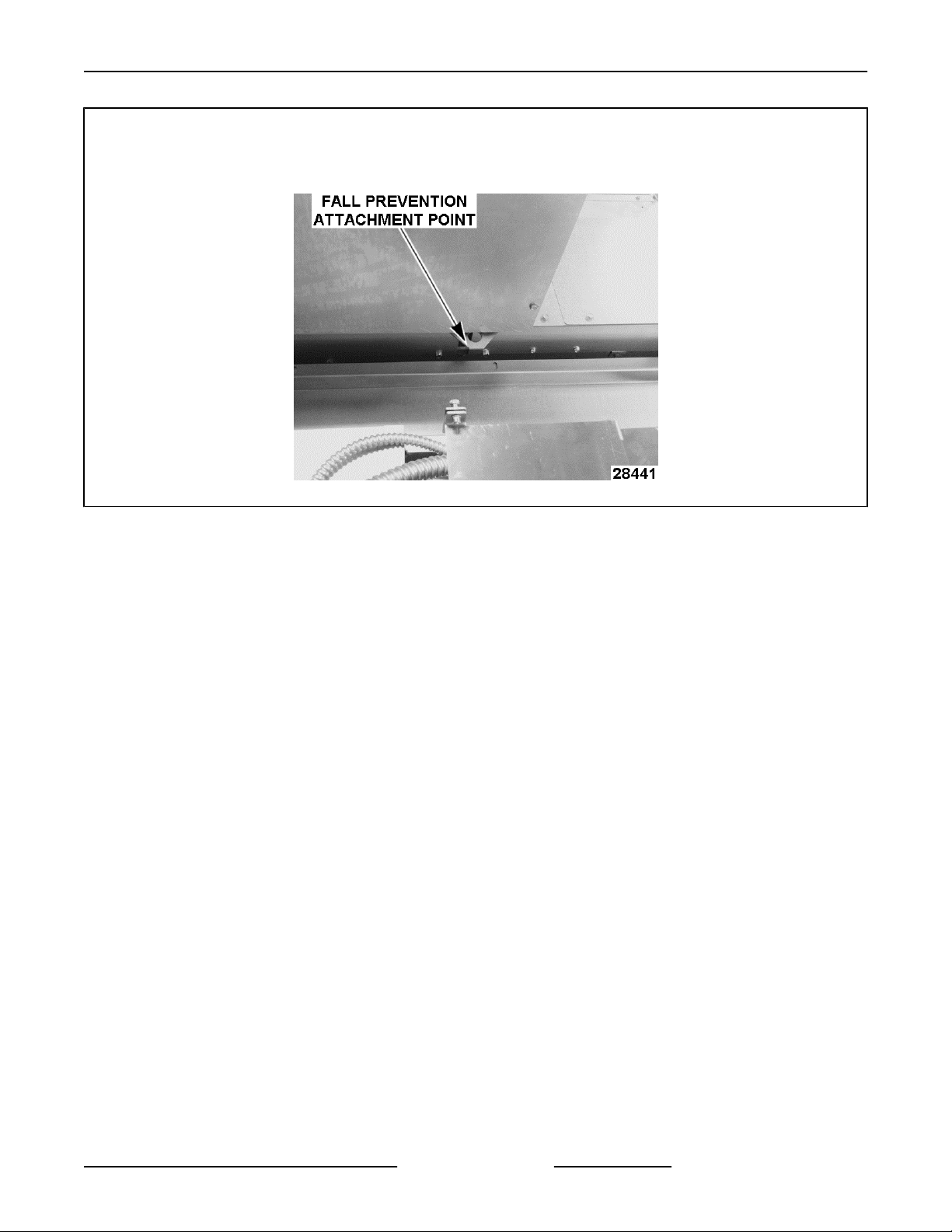
AN ATTACHMENT POINT FOR FALL PREVENTION IS LOCATED ON TOP, IN THE CENTER OF THE OVEN.
WHEN WORKING ON TOP OF OVEN, BE SURE TO SECURELY ATTACH SAFETY HARNESS TO FALL
PREVENTION ATTACHMENT POINT.
Fig. 1
Page 5 of 49 F45469 Rev. D (1019)
INSTALLATION INSTRUCTIONS OV500-EE SERIES GAS RACK OVENS AND OV500 SERIES ELECTRIC RACK
OVENS - GENERAL
GENERAL
INTRODUCTION
General
OV500G1-EE
rack and OV500G2-EE & OV500E2 rack ovens hold
two single racks or one double rack.
Oven features:
• Powered rack lift with high temperature bearings
and a clutch rotating system designed to stop the
rack in the event of a jam without damage to the
rotation motor or losing rack alignment.
• Digital programmable controller with optional
backup control, flush flooring, and field reversible
bake chamber door.
All of the information, illustrations and specifications
contained in this manual are based on the latest
product information available at the time of printing.
Heating
The rack oven reaches baking temperatures of 350°
in approximately 20 minutes; however, a 30 minute
preheat is recommended to fully heat the steam
generator.
Steaming System
Standard on all rack ovens, is a self-contained
spherical cast steam system providing excellent
steaming conditions.
& OV500E1 rack ovens hold one single
UNPACKING
Remove the crating from the oven exterior, check for
possible shipping damage. If the oven is found to be
damaged after unpacking, save the packaging
material and contact the carrier within 15 days of
delivery.
LOCATION
To reduce the risk of fire, the appliance is
to be installed on non-combustible surface only, with
no combustible material within 18 inches above the
appliance. The appliance is to be mounted on floors
of non-combustible construction with noncombustible
flooring and surface finish and with no combustible
material against the underside, or on non-combustible
slabs or arches having no combustible material
against the underside. Such construction shall in all
cases extend not less than 12 inches beyond the
equipment on all sides.
Oven not provided with a canopy hood, must be
installed under a ventilation hood.
The floor must be level with surrounding area with a
maximum slope of 1/8" per foot up to 3/4" maximum
in all directions. Floor anchors require a minimum 1"
thick solid floor substrate.
A level floor area must be prepared before assembling
oven. The floor area should be at least 104"D x 74"W
for double rack oven and 94"D x 57"W for single rack
oven, to accommodate the oven footprint and door
swing. Check the facilities floor area at the threshold
and door swing opening location to determine if
facilities floor will need to be reworked.
Do not obstruct the flow of combustion and ventilation
air. Keep the appliance area free and clear from
combustibles.
Make sure there is an adequate supply of make up air
in the room to allow for combustion.
The electrical diagram is located on the inside of the
heat exchanger compartment door.
NOTE: If the location has multiple ovens, keep the
serial numbered crates together.
Oven is UL/CSA Listed for zero clearance for back and
side
for plumbing rear drain connection.
Top of oven requires a minimum of 24" clearance for
servicing accessability.
TESTING THE GAS SUPPLY PIPING
When test pressures exceed 1/2 psig (14" W.C.)
(35.6cm W.C.) (3.5kPa), the oven and its individual
F45469 Rev. D (1019) Page 6 of 49
CLEARANCE DIMENSIONS
walls. A 1" to 4" back clearance is recommended
SYSTEM

INSTALLATION INSTRUCTIONS OV500-EE SERIES GAS RACK OVENS AND OV500 SERIES ELECTRIC RACK
OVENS - GENERAL
shutoff valve must be disconnected from the gas
supply piping system.
test pressures are 1/2 psig (14" W.C.) (35.6cm
When
W.C.) (3.5kPa) or less, the oven must be isolated from
the gas supply piping system by closing its individual
shutoff valve.
INSTALLATION CODES AND
STANDARDS
OV500 ovens must be installed in accordance with:
United States
State and local codes.
1.
2. National Fuel Gas Codes, ANSI Z223.1 (latest
edition), available from American Gas
Association, 1515 Wilson Boulevard, Arlington,
VA 22209.
3. ANSI/NFPA 96, Standard for Ventilation Control
& Fire Protection of Commercial Cooking
Operations (latest edition), available from
National Fire Protection Association,
Batterymarch Park, Quincy, MA 02269.
4. National Electrical Code, ANSI/NFPA-70 (latest
edition).
5. NSF/ANSI 4 - 2007e Standard for Commercial
Cooking, Rethermalization and Powered Hot
Food Holding & Transport Equipment.
Canada
1. Local codes.
2. CAN/CGA-B149-1, Installation for Natural Gas
Burning Appliances and Equipment (latest
edition).
3. CAN/CGA-B149-2, Installation for Propane
Burning Appliances and Equipment (latest
edition).
4. Canadian Electrical Code, Part 2, CSA Standard
C22.1 (latest edition).
Plumbing Connections
1. Water and waste piping and connections shall
comply with the International Plumbing Code
2003, International Code Council (ICC), or to the
Uniform Plumbing Code 2003, International
Association of Plumbing and Mechanical
Officials (IAPMO).
NOTE: Plumbing connections must comply with
applicable sanitary, safety and plumbing codes and
provide adequate backflow protection to comply with
applicable federal, state and local codes.
SPECIAL TOOLS
• Inclined manometer - Dwyer Cat. #1227 or
equivalent.
Combustion analyzer meter Bacharach Fyrite
•
Pro 125 Bacharach model# 24-8105 or Fyrite
"Insight" model# 24-8251(Order from Bakery
Support).
• Rotary hammer / hammer drill to drill holes in floor
for anchor bolts.
• 3/8" masonry drill bit to drill holes in floor for
anchor bolts.
• Temperature tester (thermocouple type) with 10'
lead.
• Gauges for checking air shutters Part No. 011M5689-00001 (shipped with oven).
• Draft meter BACHARACH Model 13-3000 DCL
24490 or equivalent.
• Dolly wheel Part No. 01-1M2335-00001.
• Mini laser level self leveling with tripod Harbor
Freight No. 92703-OVGA.
• 2 ton foldable shop hoist Harbor Freight No.
35915-4VGA for lifting oven section.
• 3/8" chain 20 ft. long with a 4700 lbs. load rating
Harbor Freight No. 40461-7VGA used with hoist.
• Two 7/16" X 5-1/2" bolts used with hoist.
• Two 7/16" nuts used with hoist.
• Four 7/16" fender washers used with hoist.
• Loctite® #242 Part No. 00-520228
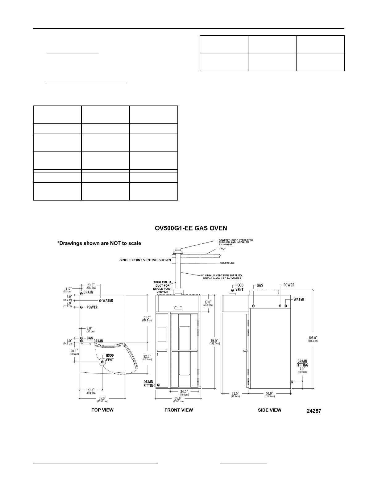
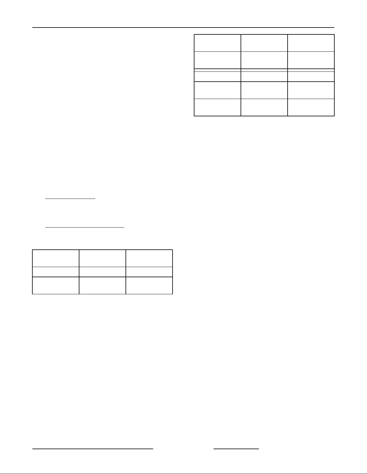
OV500G1-EE GAS OVEN
SPECIFICATIONS
1. WATER:
1/2" NPT, 30-75 PSI cold water required,
customer
line strainer.
2. DRAIN:
6 1/4" (front) or 7" (rear) connection A.F.F.
NOTES. Route to air-gap drain. Do not slope
drain upwards. Plug the drain connection that is
not in use.
Rear Drain: 1/2" NPTF
Front Drain: 1/2" NPTF
3. POWER:
to install in-line filter, shut off valve and
SEE
Page 7 of 49 F45469 Rev. D (1019)
INSTALLATION INSTRUCTIONS OV500-EE SERIES GAS RACK OVENS AND OV500 SERIES ELECTRIC RACK
OVENS - GENERAL
Two supplies required. 120/60/1 20 AMP
dedicated circuit required and one of the
following voltage options.
Voltage Full Load AMPS
208 - 240/60/1 8.8 - 7.6 AMPS
208 - 240/60/3 5.0 - 4.4 AMPS
440 - 480/60/3 2.4 - 2.2 AMPS
4. GAS:
Natural Gas (N.G.)
NPT, W.C.N.G. (N.G. rated 1025 BTU/CU. FT.
1"
SP. GR. 1.00)
Liquified Propane Gas (L.P.G.)
1" NPT, W.C.L.P.G. (L.P.G. rated 2440 BTU/
CU.FT., SP. GR. 1.52)
Natural Gas
BTU/HR 180,000 180,000
INLET
PRESSURE
MANIFOLD
PRESSURE
5. HOOD VENT:
8" DIA connection collar. Customer to supply
and ventilator fan per state and local codes.
duct
Air proving switch factory installed & integrated
with burner system operation. Oven provided
relay with max. 10 amp 1/2 H.P. @ 120V output
for fan operation. If larger, use oven relay to
control additional separately powered contactor /
relay for hood fan. Chamber vents are factory
ducted to this integral hood. 690 CFM required,
0.6" W.C. static pressure drop through hood.
Hood is UL710 Listed when grease filters are
installed. Type B gas vent can be used except
when bake products are grease laden.
NOTES:
1. A.F.F.: Above finished floor.
2. Customer responsible to finish and install all
utilities to and from oven.
3. All services must comply with all Federal, State
and Local codes.
5.0" - 10.0" W.C.
3.5" W.C. 10.0" W.C.
Liquified
Propane Gas
12.0" - 14.0"
W.C.
To reduce the risk of fire, the appliance is
to be installed on non-combustible surface only, with
no combustible material within 18 inches above the
appliance. The appliance is to be mounted on floors
of non-combustible construction with non-combustible
flooring and surface finish and with no combustible
material against the underside, or on non-combustible
slabs or arches having no combustible material
against the underside. Such construction shall in all
cases extend not less than 12 inches beyond the
equipment on all sides.
4. The floor must be of non-combustible material,
and must be level with surrounding area with a
maximum slope of 1/8" per foot up to 3/4"
maximum in all directions. Floor anchors require
a minimum 1" thick solid floor substrate.
5. Oven is UL/C-UL classified and CSA (AGA/CGA)
approved for 0" clearance on the side and rear
walls. Unit requires 1" to 4" clearance for rear
drain connection.
6. Top of oven requires a minimum of 24" for service
accessibility.
7. Customer responsible to install flue piping. Flue
must be vented outside of building.
8. Manufacturer reserves the right to make changes
in sizes and specifications.
Export Ratings
1. WATER:
1/2" NPT, 2.1-5.2 Bar cold water required,
customer to install in-line filter, shut off valve and
line strainer. Flow rate of 8 l/min..
2. DRAIN:
6 1/4" (front) or 7" (rear) connection A.F.F. SEE
NOTES. Route to air-gap drain. Do not slope
drain upwards. Plug the drain connection that is
not in use.
Rear Drain: 1/2" NPTF
Front Drain: 1/2" NPTF
3. POWER:
Two supplies required. Control Circuit:
100/50/60/1 or 208-240/50/1
1 kVA transformer supplied for control circuit
operation voltage of 110V. This is a multifunction
transformer, so output voltage should be verified
before operation. Some wiring may be required
to obtain proper output voltage.
F45469 Rev. D (1019) Page 8 of 49
Oven fan (1.1kW) 200V/50-60Hz/3ph/5.3A or
380- 415V/50Hz/3ph/ 2.8 - 2.5A.
INSTALLATION INSTRUCTIONS OV500-EE SERIES GAS RACK OVENS AND OV500 SERIES ELECTRIC RACK
OVENS - GENERAL
4. GAS:
Natural Gas (N.G.)
NPT (N.G. Rated 38.2Mj/m3 or 9120 Kcal/m3
1"
SP Gr 1.00)
Liquefied Propane Gas (LPG)
NPT (LPG Rated 90.9Mj/m3 or 21710 Kcal/m3
1"
SP Gr 1.52)
Natural Gas
RATING 45,400 Kcal/hr 45,400 Kcal/hr
INLET
PRESSURE
MANIFOLD
PRESSURE
RATING 190 Mj/hr 190 Mj/hr
INLET
PRESSURE
12.7 - 25.4 cm
W.C.
8.9 cm W.C. 25.4 cm W.C.
1.25 - 2.50 kPa 3.00 - 3.50 kPa
Liquified
Propane Gas
30.5 - 35.6 cm
W.C.
Natural Gas
MANIFOLD
PRESSURE
NOTE: Pressure not to exceed 35.6 cm W.C. or 3.5
kPa
5. HOOD VENT:
20.3 cm DIA. Connection collar. Customer is to
supply duct and ventilator fan per federal and/or
local codes. Chamber vent (steam) and
combustion exhaust are discharged into the
hood. An air proving switch is factory installed
and integrated with burner system operation. If
proper ventilation is not provided, burner will not
operate. Oven provides a relay to activate a
customer
so that when oven is powered up external fan will
operate. The hood requires a minimum of 19.5
m3/min for safe operation. For fan calculation
purposes you should assume 0.15 kPa
resistance through the hood. Grease filters
(optional) may be installed in the hood instead of
standard baffle.
supplied and powered contactor/relay,
.87 kPa 2.50 kPa
Liquified
Propane Gas
Fig. 2
Page 9 of 49 F45469 Rev. D (1019)
INSTALLATION INSTRUCTIONS OV500-EE SERIES GAS RACK OVENS AND OV500 SERIES ELECTRIC RACK
OVENS - GENERAL
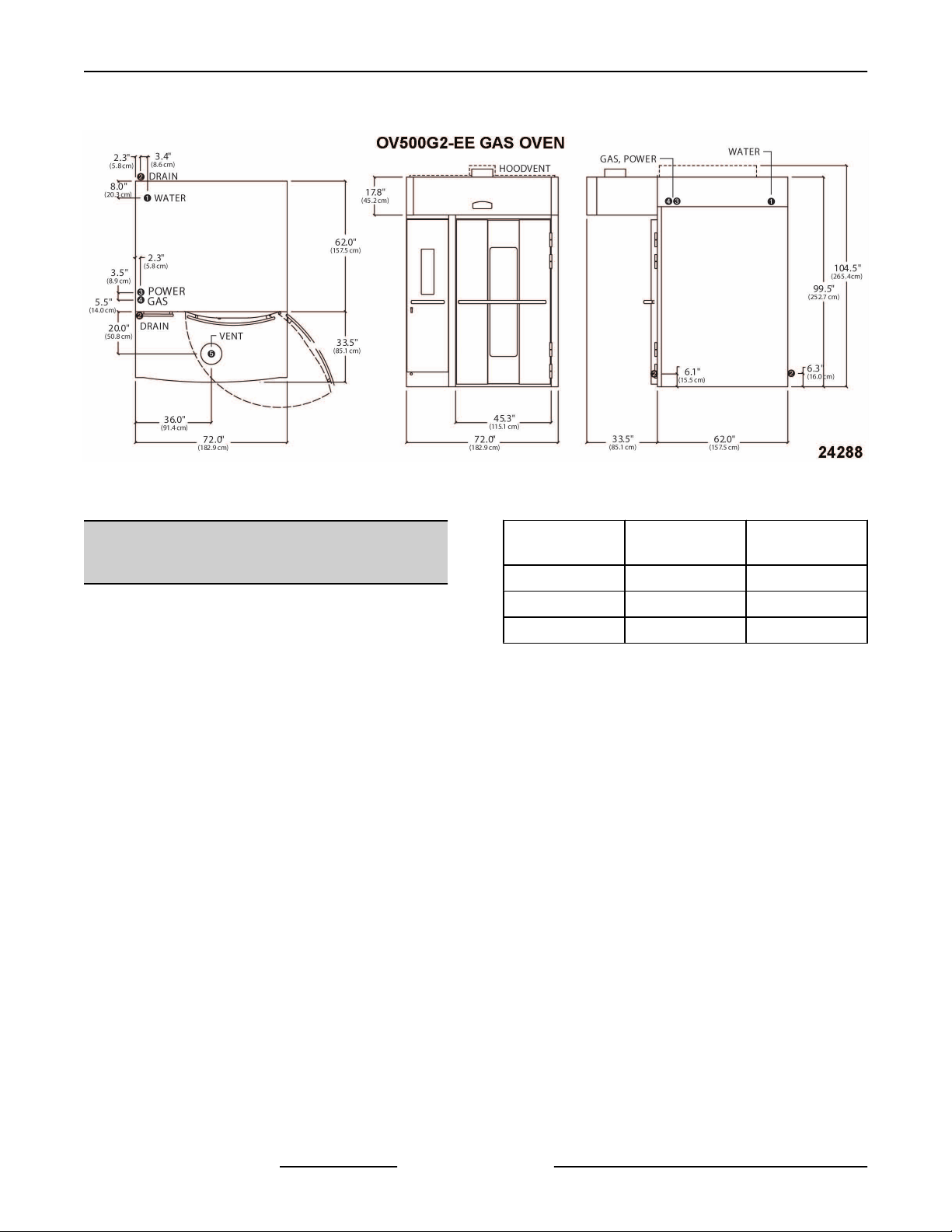
OV500G2-EE GAS OVEN
SPECIFICATIONS
1. WATER:
1/2" NPT, 30-75 PSI cold water required,
customer
line strainer.
2. DRAIN:
2 3/4" (front) or 5 1/2" (rear) connection A.F.F.
SEE NOTES. Route to air-gap drain. Do not
slope drain upwards. Plug the drain connection
that is not in use. Kit provided to extend drain to
either side of oven.
Rear Drain: 3/4" NPTF
Front Drain: 3/8" NPTF
3. POWER:
Two supplies required.
120/60/1 20 AMP dedicated circuit required and
one of the following voltage options.
208 - 240/60/1 8.8 - 7.6 AMPS
208-240/60/3 5.0 - 4.4 AMPS
440 - 480/60/3 2.4 - 2.2 AMPS
4. GAS:
Natural Gas (N.G.)
1/4" NPT, W.C.N.G. (N.G. rated 1025 BTU/CU.
1
FT. SP. GR. 1.00)
Liquified Propane Gas (L.P.G.)
1/4" NPT, W.C.L.P.G. (L.P.G. rated 2440 BTU/
1
CU.FT., SP. GR. 1.52)
BTU/HR 275,000 275,000
INLET
PRESSURE
MANIFOLD
PRESSURE
5. HOOD VENT:
10" DIA connection collar. Air proving switch
factory
operation. Oven provided rely with max. 10 amp
1/2 H.P. @ 120V output for fan operation. If
larger, use oven relay to control additional
separately powered contactor / relay for hood
to install in-line filter, shut off valve and
Voltage Full Load AMPS
Natural Gas
5.0 -10.0" W.C.
3.5" W.C. 8.75" W.C.
installed & integrated with burner system
Liquified
Propane Gas
10.0" - 14.0"
W.C.
fan. Customer to supply duct and ventilator fan
per state and local codes. Chamber vents are
factory ducted to this integral hood. 900 CFM
required, 0.6" W.C. static pressure drop through
hood. Hood is UL710 Listed when grease filters
are installed. Type B gas vent can be used except
when bake products are grease laden.
NOTES:
1. A.F.F.: Above finished floor.
2. Customer responsible to finish and install all
utilities to and from oven.
3. All services must comply with all Federal, State
and Local codes.
To reduce the risk of fire, the appliance is
to be installed on non-combustible surface only, with
no combustible material within 18 inches above the
appliance. The appliance is to be mounted on floors
of non-combustible construction with non-combustible
flooring and surface finish and with no combustible
material against the underside, or on non-combustible
slabs or arches having no combustible material
against the underside. Such construction shall in all
cases extend not less than 12 inches beyond the
equipment on all sides.
4. The floor must be of non-combustible material,
and must be level with surrounding area with a
maximum slope of 1/8" per foot up to 3/4"
maximum in all directions. Floor anchors require
a minimum 1" thick solid floor substrate.
5. Oven is UL/C-UL classified and CSA (AGA/CGA)
approved for 0" clearance on the side and rear
walls. Unit requires 1" to 4" clearance for rear
drain connection.
6. Top of oven requires a minimum of 24" for service
accessibility.
7. Customer responsible to install flue piping. Flue
must be vented outside of building.
8. Manufacturer reserves the right to make changes
in sizes and specifications.
Export Ratings
1. WATER:
1/2” NPT, 2.1-5.2 Bar cold water required,
customer to install in-line filter, shut off valve and
line strainer. Flow rate of 8 l/min..
2. DRAIN:
F45469 Rev. D (1019) Page 10 of 49
INSTALLATION INSTRUCTIONS OV500-EE SERIES GAS RACK OVENS AND OV500 SERIES ELECTRIC RACK
OVENS - GENERAL
2 3/4" (front) or 5 1/2" (rear) connection A.F.F.
Route to air-gap drain. Do not slope drain
upwards.
use. Kit provided to extend drain to either side of
oven.
Rear Drain: 3/4" NPTF
Front Drain: 3/8" NPTF
3. POWER:
Two supplies required. Control circut:
100/50/60/1 or 208-240/50/1
1 kVA transformer supplied for control circuit
operation voltage of 110V. This is a multifunction
transformer, so output voltage should be verified
before operation. Some wiring may be required
to obtain proper output voltage.
Oven fan (1.1kW) operates @ 200/50/60/3 amps
or 380-415/50/3, 2.8-2.5 amps
4. GAS:
Natural Gas (N.G.)
1/4” NPT (N.G. Rated 38.2Mj/m3 or 9120 Kcal/
1
m3 SP Gr 1.00)
Liquefied Propane Gas (LPG)
3/4” NPT (LPG Rated 90.9Mj/m3 or 21710 Kcal/
m3 SP Gr 1.52)
RATING 69,300 Kcal/hr 69,300 Kcal/hr
INLET
PRESSURE
Plug the drain connection that is not in
Natural Gas
12.7 - 25.4 cm
W.C.
Liquified
Propane Gas
30.5 - 35.6 cm
W.C.
Natural Gas
MANIFOLD
PRESSURE
RATING 290 Mj/hr 290 Mj/hr
INLET
PRESSURE
MANIFOLD
PRESSURE
NOTE: Pressure not to exceed 35.6 cm W.C. or 3.5
kPa
5. HOOD VENT:
25.4 cm DIA. Connection collar. Customer is to
supply duct and ventilator fan per federal and/or
local codes. Chamber vent (steam) and
combustion exhaust are discharged into the
hood. An air proving switch is factory installed
and integrated with burner system operation. If
proper ventilation is not provided, burner will not
operate. Oven provides a relay to activate a
customer
so that when oven is powered up external fan will
operate. The hood requires a minimum of 25.5
m3/min for safe operation. For fan calculation
purposes you should assume 0.15 kPa
resistance through the hood. Grease filters
(optional) may be installed in the hood instead of
standard baffle.
8.9 cm W.C. 22.22 cm W.C.
1.25 - 3.50 kPa 3.00 - 3.50 kPa
.87 kPa 2.18 kPa
supplied and powered contactor/relay,
Liquified
Propane Gas
Page 11 of 49 F45469 Rev. D (1019)
INSTALLATION INSTRUCTIONS OV500-EE SERIES GAS RACK OVENS AND OV500 SERIES ELECTRIC RACK
OVENS - GENERAL
Fig. 3
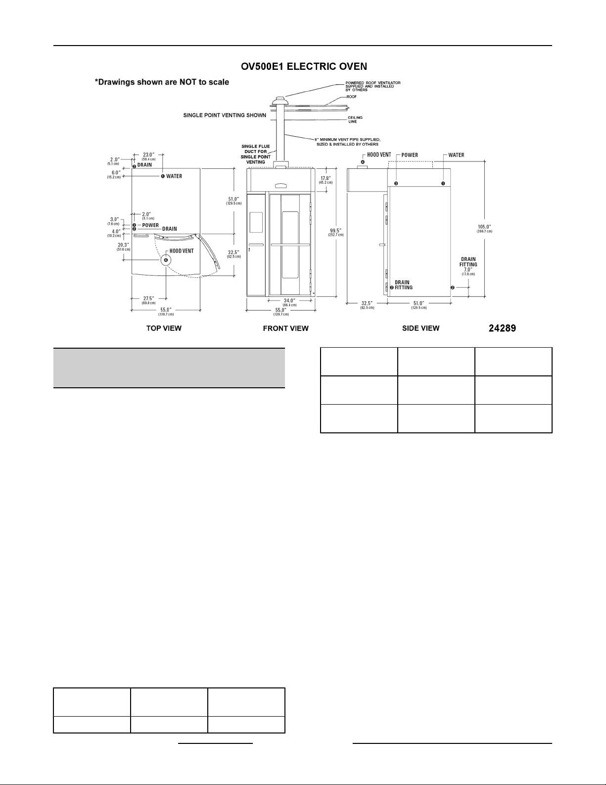
OV500E1 ELECTRIC OVEN
SPECIFICATIONS
1. WATER:
1/2" NPT, 30-75 PSI cold water required,
customer to install in-line filter, shut off valve and
line strainer.
2. DRAIN:
6 1/4" (front) or 7" (rear) connection A.F.F. .
Route to air-gap drain. Do not slope drain
upwards. Plug the drain connection that is not in
use.
Rear Drain: 1/2" NPTF
Front Drain: 1/2" NPTF
3. POWER:
Two supplies required.
120/60/1 20 AMP dedicated circuit required and
one of the following voltage options.
Heating Circuit: KW rating in following chart per
supply voltage.
Blower Motor: 1 1/2 H.P.
Voltage
208/60/3 100 AMPS 34 KW
208 - 240/60/3 76 - 87 AMPS 26 - 34 KW
440 - 480/60/3 40 - 43 AMPS 29 - 34 KW
4. HOOD VENT:
8" DIA connection collar. Customer to supply
duct and ventilator fan per state and local codes.
Oven provided relay with max. 10 amp 1/2 H.P.
@ 120V output for fan operation. If larger, use
oven relay to control additional separately
powered contactor / relay for hood fan. Chamber
vents are factory ducted to this integral hood. 690
CFM required, 0.6" W.C. static pressure drop
through hood. Hood is UL710 Listed when
grease filters are installed. Type B gas vent can
be used except when bake products are grease
laden.
NOTES:
1. A.F.F.: Above finished floor.
2. Customer responsible to finish and install all
utilities to and from oven.
3. All services must comply with all Federal, State
and Local codes.
Full Load
AMPS
Heaters Rating
F45469 Rev. D (1019) Page 12 of 49

INSTALLATION INSTRUCTIONS OV500-EE SERIES GAS RACK OVENS AND OV500 SERIES ELECTRIC RACK
OVENS - GENERAL
To reduce the risk of fire, the appliance is
to be installed on non-combustible surface only, with
no combustible material within 18 inches above the
appliance. The appliance is to be mounted on floors
of non-combustible construction with noncombustible
flooring and surface finish and with no combustible
material against the underside, or on non-combustible
slabs or arches having no combustible material
against the underside. Such construction shall in all
cases extend not less than 12 inches beyond the
equipment on all sides.
4. The floor must be of non-combustible material,
and must be level with surrounding area with a
maximum slope of 1/8" per foot up to 3/4"
maximum in all directions. Floor anchors require
a minimum 1" thick solid floor substrate.
5. Oven is UL/C-UL classified and CSA (AGA/CGA)
approved for 0" clearance on the side and rear
walls. Unit requires 1" to 4" clearance for rear
drain connection.
6. Top of oven requires a minimum of 24" for service
accessibility.
7. Customer responsible to install flue piping. Flue
must be vented outside of building.
8. Manufacturer reserves the right to make changes
in sizes and specifications.
Export Ratings
1. WATER:
1/2” NPT, 2.1 - 5.2 Bar cold water required,
customer to install in-line filter, shut off valve and
line strainer. Flow rate of 8 l/min.
2. DRAIN:
N/A
3. POWER:
Two supplies required. 100V/50-60Hz/1Ph or
208-240V/50Hz/1Ph
⅛ kVA transformer supplied for control circuit
operation
transformer, so output voltage should be verified
before operation. Some wiring may be required
to obtain proper output voltage.
Oven fan (1.1kW) operates @ 200V/50-60Hz/
3Ph, 5.3 amps or 380-415V/3Ph/50Hz/ 2.4-2.2A
Voltage
200/50 - 60/3 74 AMPS 24 KW
380 - 415/50/3 46 - 50 AMPS 29 - 34 KW
4. HOOD VENT:
20.3 cm DIA. Connection collar. Customer is to
supply duct and ventilator fan per federal and/or
local codes. Chamber vent (steam) and
combustion exhaust are discharged into the
hood. Oven provides a relay to activate a
customer
so that when oven is powered up external fan will
operate. The hood requires a minimum of 19.5
m^3/min for safe operation. For fan calculation
purposes you should assume 0.15 kPa
resistance through the hood. Grease filters
(optional) may be installed in the hood instead of
standard baffle.
voltage of 110V. This is a multifunction
Full Load
AMPS
supplied and powered contactor/relay,
Heaters Rating
Page 13 of 49 F45469 Rev. D (1019)
INSTALLATION INSTRUCTIONS OV500-EE SERIES GAS RACK OVENS AND OV500 SERIES ELECTRIC RACK
OVENS - GENERAL
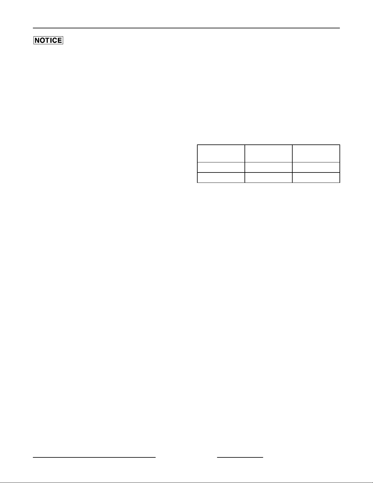
OV500E2 ELECTRIC OVEN
SPECIFICATIONS
1. WATER:
1/2" NPT, 30-75 PSI cold water required,
customer
line strainer.
2. DRAIN:
2 3/4" (front) or 5 1/2" (rear) connection A.F.F. .
Route to air-gap drain. Do not slope drain
upwards. Plug the drain connection that is not in
use. Kit provided to extend drain to either side of
oven.
Rear Drain: 3/4" NPTF
Front Drain: 3/8" NPTF
3. POWER:
Two supplies required.
120/60/1 20 AMP dedicated circuit required and
one of the following voltage options.
Heating Circuit: KW rating in following chart per
supply voltage.
Blower Motor: 1 1/2 H.P.
Voltage
208/60/3 146.4 AMPS 51.3 KW
to install in-line filter, shut off valve and
Full Load
AMPS
Heaters Rating
Fig. 4
Voltage
208 - 240/60/3
440 - 480/60/3
4. HOOD VENT:
10"DIA connection collar. Customer to supply
duct
and ventilator fan per state and local codes.
Oven provided relay with max. 10 amp 1/2 H.P.
@ 120V output for fan operation. If larger, use
oven relay to control additional separately
powered contactor / relay for hood fan. Customer
to supply duct and ventilator fan per state and
local codes. Chamber vents are factory ducted to
this integral hood. 900 CFM required, 0.6" W.C.
static pressure drop through hood. Hood is
UL710 Listed when grease filters are installed.
Type B gas vent can be used except when bake
products are grease laden..
NOTES:
1. A.F.F.: Above finished floor.
2. Customer responsible to finish and install all
utilities to and from oven.
3. All services must comply with all Federal, State
and Local codes.
Full Load
AMPS
111.2 - 127.2
AMPS
59.1 - 64.1
AMPS
Heaters Rating
38.5 - 51.3 KW
43 - 51.3KW
F45469 Rev. D (1019) Page 14 of 49
INSTALLATION INSTRUCTIONS OV500-EE SERIES GAS RACK OVENS AND OV500 SERIES ELECTRIC RACK
OVENS - GENERAL
To reduce the risk of fire, the appliance is
to be installed on non-combustible surface only, with
no combustible material within 18 inches above the
appliance. The appliance is to be mounted on floors
of non-combustible construction with noncombustible
flooring and surface finish and with no combustible
material against the underside, or on non-combustible
slabs or arches having no combustible material
against the underside. Such construction shall in all
cases extend not less than 12 inches beyond the
equipment on all sides.
4. The floor must be of non-combustible material,
and must be level with surrounding area with a
maximum slope of 1/8" per foot up to 3/4"
maximum in all directions. Floor anchors require
a minimum 1" thick solid floor substrate.
5. Oven is UL/C-UL classified and CSA (AGA/CGA)
approved for 0" clearance on the side and rear
walls. Unit requires 1" to 4" clearance for rear
drain connection.
6. Top of oven requires a minimum of 24" for service
accessibility.
7. Customer responsible to install flue piping. Flue
must be vented outside of building.
8. Manufacturer reserves the right to make changes
in sizes and specifications.
Export Ratings
1. WATER:
1/2” NPT, 2.1 - 5.2 Bar cold water required,
customer to install in-line filter, shut off valve and
line strainer. Flow rate of 8 l/min.
2. DRAIN:
N/A
3. POWER:
Two supplies required. 100V/50-60Hz/1Ph or
208-240V/50Hz/1Ph
⅛ kVA transformer supplied for control circuit
operation
transformer, so output voltage should be verified
before operation. Some wiring may be required
to obtain proper output voltage.
Oven fan (1.1kW) operates @ 200V/50-60Hz/
3Ph/5.3A or 380-415V 3ph 50 Hz 2.4- 2.2A
Voltage
200/50 - 60/3 108 AMPS 36 KW
380 - 415/50/3 68 - 73AMPS 43 - 51 KW
4. HOOD VENT:
25.4 cm DIA. Connection collar. Customer is to
supply duct and ventilator fan per federal and/or
local codes. Chamber vent (steam) and
combustion exhaust are discharged into the
hood. Oven provides a relay to activate a
customer
so that when oven is powered up external fan will
operate. The hood requires a minimum of 25.5
m3/min for safe operation. For fan calculation
purposes you should assume 0.15 kPa
resistance through the hood. Grease filters
(optional) may be installed in the hood instead of
standard baffle.
voltage of 110V. This is a multifunction
Full Load
AMPS
supplied and powered contactor/relay,
Heaters Rating
Page 15 of 49 F45469 Rev. D (1019)
 Loading...