

Page 1

DECK OVENS
Operator
Manual
OV450N
OV452N
OV450W
Model Number: ___________
Serial Number: ___________
Date of Installation: ___________
Baxter Mfg, a Division of ITW FEG, LLC • 19220 State Route 162 East • Orting, WA 98360-9236
Phone: (360) 893-5554 • Fax: (360) 893-1337
www.baxterbakery.com
FORM 36728 (January 2014)
Page 2

TABLE OF CONTENTS
GENERAL .............................................................................................................................................3
INST ALLATION .....................................................................................................................................4
Unpacking ........................................................................................................................................ 4
Installation Codes and Standards .................................................................................................... 4
Water Requirements ........................................................................................................................ 4
Location ........................................................................................................................................... 5
Plumbing Connections ..................................................................................................................... 5
Drain Connections ........................................................................................................................... 5
Electrical Connections ..................................................................................................................... 5
Vent Hood ........................................................................................................................................ 5
Before First Use ............................................................................................................................... 6
Dimensions Diagram ....................................................................................................................... 6
OPERATION .......................................................................................................................................... 7
Door Opening and Closing .............................................................................................................. 7
Controls ........................................................................................................................................... 8
Turning On/Off Oven ..................................................................................................................... 10
Turning On/Off Oven Light ............................................................................................................. 10
Setting the Top Heat ...................................................................................................................... 10
Setting the Bottom Heat .................................................................................................................11
Setting the Baking Timer ................................................................................................................11
Setting the Steam Timer .................................................................................................................11
Setting Vent Operation .................................................................................................................. 12
Operation of Bake and Steam ...................................................................................................... 13
CLEANING .......................................................................................................................................... 13
Daily Cleaning ............................................................................................................................... 13
Cleaning the Door Glass ............................................................................................................... 14
MAINTENANCE .................................................................................................................................. 15
Lamp Replacement ....................................................................................................................... 15
Service and Parts Information ....................................................................................................... 16
©BAXTER MFG, 2014
– 2 –
Page 3

INSTALLATION, OPERATION AND CARE OF
OV450 & OV452 SERIES DECK OVENS
SAVE THESE INSTRUCTIONS
GENERAL
The OV450 & OV452 Series Deck Ovens (Fig. 1) are designed and suited for your baking needs. The
deck ovens are available in three sizes: OV450N, OV450W, and OV452N. The OV450N and OV450W
single baking chamber decks are confi gurable from 1 to 4 units high. The OV452N double baking chamber
deck is confi gurable in either 1 to 3 units high. They are produced with quality workmanship and material.
Proper installation, usage and maintenance of the ovens will result in years of satisfactory performance.
It is suggested that you thoroughly read this manual and carefully follow the instructions provided.
Fig. 1
– 3 –
Page 4
INSTALLATION
The OV450 & OV452 Series Deck Ovens require some assembly and must be installed by authorized
Bakery Systems trained service technicians.
UNPACKING
This oven was inspected before leaving the factory . The transportation company assumes full responsibility
for safe delivery upon acceptance of the shipment. Immediately after receiving the oven, check for possible
shipping damage. If the oven is found to be damaged, save the packaging material and contact the carrier
within 15 days of delivery.
Carefully unpack the oven and place in a work-accessible area as near to its fi nal installed position as
possible. Verify all packaging material has been removed from the interior of each deck. Remove protective
covering from exterior surfaces prior to placing oven in its fi nal location.
Prior to installation, verify that the electrical and the water service agrees with the specifi cations on the
oven data plate and in this manual.
INSTALLATION CODES AND STANDARDS
In the United States, the Deck Oven must be installed in accordance with:
1. State and local codes.
2. National Electrical Code (ANSI/NFP A No.70, latest edition) available from the National Fire Protection
Association, Batterymarch Park, Quincy, MA 02269.
In Canada, the Deck Oven must be installed in accordance with:
1. Local codes.
2. Canadian Electrical Code (CSA C22.2 No.3, latest edition) available from the Canadian Standards
Association, 5060 Spectrum Way, Mississauga, Ontario, Canada L4W 5N6.
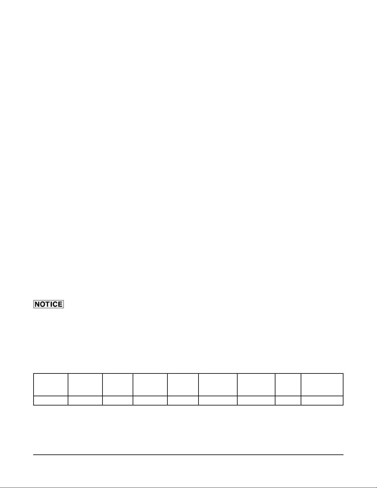
WATER REQUIREMENTS
As with all steam related products, water fi ltration and regular fi lter replacements, coupled with
routine deliming, are required. Y our local Service offi ce can recommend a water treatment system to meet
the needs of your local water conditions. Contact your local Service representative for water treatment
offerings.
Proper water quality can improve the taste of the food prepared in the oven, reduce liming and extend
equipment life. Local water conditions vary from one location to another. The recommended proper water
treatment for effective and effi cient use of this equipment will also vary depending on the local water
conditions. Ask your municipal water supplier for details about your local water supply prior to installation.
Dynamic
Water
Pressure
30-80 PSIG
Hardness Silica
2-4 grains < 13 ppm < 30 ppm 7-8 0 ppm < 20 ppm < 60 ppm < 5 microns
Total Chlo-
ride
pH Range
Chlorine &
Chloramine
Alkalinity TDS
Undissolved
Solids
Water hardness above 4.0 grains per gallon should be treated by a water conditioner (water softener and/
or in-line water treatment). Water hardness below 2.0 grains per gallon may also require a water treatment
system to reduce potential corrosion. Water treatment has been shown to reduce costs associated with
machine cleaning, reduce deliming and reduce corrosion of metallic surfaces.
– 4 –
Page 5
LOCATION
Allow space for operating the oven. The oven requires approximately 3" from the back of the oven for
electrical and plumbing connections. Do not obstruct the ventilation ports on the sides or back of the
oven. To prevent heat accumulation, 1" clearance is required from any wall. The oven must be installed
on an approved stand. Minimum clearance of 60" must be provided in front of the oven so the oven can
be pulled forward for servicing.
PLUMBING CONNECTIONS
Water and waste piping and connections shall comply with the International Plumbing Code 2003,
International Code Council (ICC), or to the Uniform Plumbing Code 2003, International Association of
Plumbing and Mechanical Offi cials (IAPMO).
Plumbing connections must comply with applicable sanitary, safety and plumbing
codes and provide adequate backfl ow protection to comply with applicable federal, state and local
codes.
Connect the cold water supply to the
3
/8" NPT connection located at the rear of the oven. Water supply
should have a pressure of 30 to 80 psi. The oven is supplied with a fl ow regulator which must be installed.
DRAIN CONNECTIONS
In order to avoid any back pressure in the oven, do not connect solidly to any drain. Drain
connections from each deck to the collector box must be high temperature hose.
Connect the
1
/2" drain connection from each deck to the collector box on the deck oven stand. Route the
drain line from the collector box to a fl oor drain. An air gap is provided by the collector box. No air gap
required at fl oor drain.
ELECTRICAL CONNECTIONS
NOTE: The oven must be installed with the provided lanyard securely attached to one deck and to the
wall. Verify that all connections are long enough so that the oven can be pulled forward to the extent of
the lanyard without straining any connections.
Electrical and grounding connections must comply with the applicable portions of
the National Electrical Code and/or other local electrical codes.
Disconnect the electrical power to the unit and follow lockout / tagout procedures.
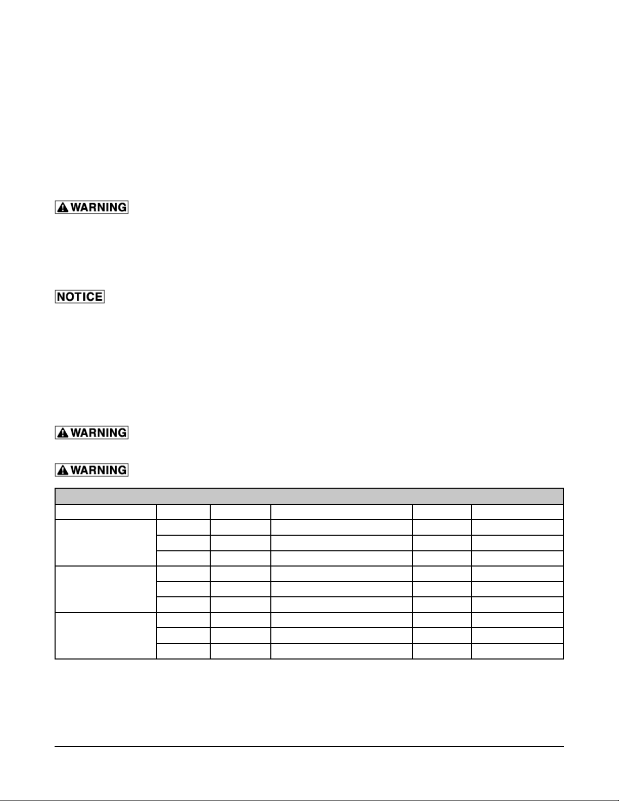
ELECTRICAL DATA (Per Deck)
Model Voltage Total kW Maximum Operating kW Amperage Circuit Breaker
208 5.75 4.2 11.6 20A
OV450N
OV450W
OV452N
220 6.4 4.7 12.3 20A
230 7 5.1 12.8 20A
208 9.72 7.35 20.4 30A
220 10.9 8.3 21.6 30A
230 11.9 9 22.3 30A
208 5.65 4.1 11.4 20A
220 6.3 4.6 12 20A
230 6.9 5 12.6 20A
NOTE: The OV452N requires 2 electrical services.
VENT HOOD
Some local codes may require the oven to be located under an exhaust hood. Information on the construction
and installation of ventilating hoods may be obtained from V apor Removal from Cooking Equipment, NFP A
Standard No. 96 (latest edition).
– 5 –
Page 6

BEFORE FIRST USE
Before using the oven for the fi rst time, when new stones are installed, or if the stones have been cleaned
with water, the baking stones need to be slowly "baked in" prior to start-up. Use the following chart as a
guide to properly season the baking stones.
CONTROLS
Parameter Step 1 Step 2 Step 3 Step 4 Step 5
Top Heat
Bottom Heat
150°F 250°F 350°F 450°F 550°F
150°F 250°F 350°F 450°F 550°F
Baking Time 30 Minutes 30 Minutes 30 Minutes 30 Minutes 30 Minutes
Steam None None None None None
Steam Vent Open Open Open Open Open
DIMENSIONS DIAGRAM
Model A B C
OV450N
OV450W
OV452N
5
38
/16" 24" 1219/64"
15
61
/16" 473/4" 1219/64"
5
/16" 24" 19"
38
– 6 –
Page 7

OPERATION
The oven and its parts are hot. Use care when operating, cleaning or servicing the
oven. The baking compartment contains live steam. Stay clear when opening door.
DOOR OPENING AND CLOSING
To open the door (Fig. 2), pull down on the door
handle slightly to allow steam to escape.
After steam escapes, continue pulling down on the
door handle until the door is fully open.
To close the door (Fig. 2), lift the door with the door
handle until the door closes.
Fig. 2
Fig. 3
– 7 –
Page 8

CONTROLS
There is a control for each oven deck. When the oven is turned on,
the oven will begin to heat to the set temperature of both the Top
and Bottom Heat. The timer does not control the oven. Each control
panel has three numeric display windows. They are:
• TOP HEA T WINDOW - Displays the actual temperature for
the Top Heat. The temperature range is 50˚ to 550˚F.
• TIMER/STEAM WINDOW – Displays the timer or steam
timer setting. The range is 00 to 999 minutes for the bake
timer and 00 to 199 seconds for the steam timer.
• LOWER HEAT WINDOW - Displays the actual temperature
for the Lower Heat. The temperature range is 50˚ to 550˚F.
CONTROL PANEL BUTTONS
ON/OFF
Button
Light Button Use this button to turn the light on or off. The button LED is on when the cavity
Heat Button Use this button with the "+" and "-" buttons to set the temperature. Range 50˚ to
Baking Timer
Button
Use this button to turn the oven on or off. The button LED is on when the oven is
turned on.
light is on.
550˚F. Button LED will fl ash when in set mode. Button LED is solid when heating
elements are energized. Press to see set temperature.
Use this button with the "+" and "-" buttons to set the bake timer. Range is 00999 minutes. Button LED will fl ash when in the set mode.
– 8 –
Page 9

CONTROL PANEL BUTTONS
Vent Button Use this button to program the vent to open and close for a recipe. If not
programmed it will open and close the vent manually during recipe when
pressed. The LED indicates the vent is open. See Setting Vent Operation to set.
"+" Button Use this button to increase the setting feature such as temperature or time.
"-" Button Use this button to decrease the setting feature such as temperature or time.
STARTSTOP Button
Steam
System
Button
Steam
Button
Steam Timer
Button
Buttons Not Used.
Use this button to start or stop the timing function. The LED on indicates the timer
is running.
Use this button to turn on or turn off steam system. Upper right red LED
indicates that steam system is on. Lower left LED indicates that steam system
is ready to steam. If the lower left LED is on the system is heating and not up
to temperature. When the lower left LED goes out the system is up to temp and
ready to use.
Use this button to manually steam. Flashing LED will indicate steaming is active.
Use this button to set the steam timer. LED will fl ash when in the set mode and
the time will fl ash in the timer window. LED will fl ash when steam time is set and
timer is not running. Use the "+" and "-" to adjust the steam time.
– 9 –
Page 10

TURNING ON/OFF OVEN
1. Press the On/Off Button to turn oven on. The button LED
will illuminate when on. The actual temperatures will appear
in the display windows.
NOTE: Oven lights will not be on until light button is pressed.
2. Press the ON/OFF button to turn oven off. The button LED
will turn off and all displays will be blank.
TURNING ON/OFF OVEN LIGHT
NOTE: The oven light will turn on even if the oven is off.
1. When the oven is turned on, press the light button to turn
on light. The button LED will illuminate and oven light will
turn on.
2. Press the light button again to turn off light.
SETTING THE TOP HEAT
1. Press the top heat button.The LED on the button will fl ash.
2. Press the "+" or "-" buttons to adjust the set point.
NOTE: The display set will increment by 1˚ each time the "+"
or "-" button is pressed. Press and hold the "+" or "-" button to
increment by 10˚.
3. After pressing the "+" or "-" button, wait 10 seconds to allow
the new top heat setting to save or you can also press the
top heat button. The LED on the button will stop fl ashing
and the actual top heat temperature will be displayed.
400
– 10 –
Page 11

SETTING THE BOTTOM HEAT
1. Press the bottom heat button.The LED on the button will
fl ash.
2. Press the "+" or "-" buttons to adjust the set point.
NOTE: The display set will increment by 1˚ each time the "+"
or "-" button is pressed. Press and hold the "+" or "-" button to
increment by 10˚.
3. After pressing the "+" or "-" button, wait 10 seconds to
allow the new bottom heat setting to save or you can also
press the bottom heat button. The LED on the button will
stop fl ashing and the actual bottom heat temperature will
be displayed.
NOTE: By pressing both upper and lower heat buttons, you can
adjust both temps at the same time. T o see set temperature press
the top or bottom heat button.
SETTING THE BAKING TIMER
375
1. Press the bake timer button to set the timer. The LED on
the button will fl ash.
2. Press the "+" or "-" buttons to adjust the bake time.
NOTE: The display will increment by 1 minute each time the "+"
or "-" button is pressed. Press and hold the "+" or "-" button to
increment by 10 minute jumps.
3. After pressing the "+" or "-" button, wait 10 seconds to allow
the new bake time setting to save or you can also press the
bake timer button. The LED on the button will stop fl ashing
and the new bake time setting will be set and displayed.
SETTING THE STEAM TIMER
NOTE: The timer LED will fl ash if there is time programmed into
it.
1. Press the steam timer button to set the timer. The LED on
the button will fl ash and time will fl ash in the timer widow.
2. Press the "+" or "-" buttons to adjust the steam time.
00
00
NOTE: The display will increment by 1 second each time the
button is pressed.
3. After pressing the "+" or "-" button, wait 10 seconds to allow
the new steam time setting to save or you can also press
the steam timer button. The LED on the button will keep
fl ashing and the new steam time setting will be set.
NOTE: T o see the steam set time, press the steam timer button.
– 11 –
Page 12

SETTING VENT OPERATION
1. T o program the vent, press the vent button. The vent button
LED will turn on and “OFF” will appear in the top heat
window. This is vent time delay. This is the delay from the
start of the program until the vent will open.
2. Set the time by pressing the "+" or "-" button to increase or
decrease the time.
NOTE: If no buttons are pushed during the vent programming
for 5 seconds, the parameter will not be saved and will back out
of the vent programming.
3. Press the vent button again and “ON” will appear in the top
heat window. This is how long the vent is open for.
4. Adjust the time by pressing the "+" or "-" button to increase
or decrease the time.
0FF
0
136
0n
0
5. Press the vent button again to save vent parameters.
NOTE: The vent can be opened and closed during a recipe at
any time by pressing the vent button, if the vent has not been
programmed. The LED on the vent button will illuminate when
the vent is open.
136
111
20
138
– 12 –
Page 13

OPERATION OF BAKE AND STEAM
NOTE: If steam is to be used during the baking process, make
certain that the upper right LED is illuminated and the lower left LED
is out on the steam system button before starting the bake process.
425
35
1. Open the door and load the product into the oven.
2. When all the product is loaded, close the door, and then press
the START/STOP button. The START/STOP button LED will
turn on indicating that the oven has started timing down. The
time display will count down.
NOTE: If the steam timer has been set, the steam timer button LED
will be fl ashing.
3. The steam cycle will automatically start if steam time has been
programmed..
4. When the bake time has elapsed, the bake timer display will
show 00 and an alarm will sound. Press the START/STOP to
silence the alarm and it will reset the timer to the previous setting.
The baking compartment contains live steam. Stay clear when opening door.
5. Open the door and remove the product.
CLEANING
Disconnect the electrical power to the machine and follow lockout / tagout procedures.
405
The oven and its parts are hot. Use care when operating, servicing or cleaning the
oven.
DAILY CLEANING
• Always allow the oven to cool before cleaning. Never attempt to cool the oven down with water.
Sudden temperature changes could damage the glass or baking stones.
• Use care when cleaning around sensitive interior parts, such as probes and sensors.
• Sweep loose particles off the baking stones. Gently scrape off any hardened material on baking
stone. Do not use a wire brush or metal scrapper.
• Using a clean cloth moistened in warm, soapy water, wash the interior of the oven cavity. Rinse
with rag moistened with clean water and dry with a clean cloth. Be careful not to drip onto the
stone. This could cause the stone to crack when heated back up.
• Clean the outside daily with a clean, damp cloth.
• Do not use cleaners containing grit, abrasive materials, bleach, harsh chemicals or chlorinated
cleaners. Do not use steel wool on stainless steel surfaces. Never spray down the oven with water,
steam or power wash.
• Be cautious with new or improved cleaning formulas; use only after being well tested in an
inconspicuous place.
– 13 –
Page 14

CLEANING THE DOOR GLASS
Allow the glass to cool before cleaning. Cleaning while hot may cause the glass to
shatter.
1. Open oven door.
2. Place hands fl at on the glass (Fig. 4 & 5).
3. Gently slide glass toward you. Make sure to slide evenly from both sides.
Fig. 4 Fig. 5
4. Once removed, clean both sides of the glass.
5. Reinstall glass by placing both side edges of
the glass in the door frame track (Fig. 6) and
gently slide into place.
6. Check operation of the door to make sure it will
open and close without any interference.
TRACK
Fig. 6
– 14 –
Page 15

MAINTENANCE
Disconnect the electrical power to the machine and follow lockout / tagout procedures.
LAMP REPLACEMENT
NOTE: Do not touch the replacement bulb with your fi ngers. Touching the replacement bulb will shorten
bulb life. Wear gloves when replacing halogen lamps.
T o replace an oven cavity bulb, you will need a small fl at-tip screwdriver, a 7mm nut driver , and a replacement
bulb (Baxter part number 01-1000V7-00049).
Front Lamp (All Models)
1. Remove the thumb screws (Fig. 7) on the left side of the control panel.
2. Swing open control panel.
3. If necessary, loosen (do not remove) the 7mm screws (Fig. 8) on the top and bottom of the lamp
fi xture.
4. Remove lamp fi xture by sliding the fi xture up and over the screws.
5. Loosen (do not remove) the two screws (Fig. 9) that hold the bulb in the socket. They are the screws
next to the metal plate, one on each side.
6. Remove bulb.
7. Install new bulb into fi xture sockets (Fig. 9). The metal prongs (Fig. 9) insert into the sockets of the
fi xture. It does not matter which prong goes in which socket.
8. Tighten the socket screw (Fig. 9).
9. Place lamp fi xture back into opening and slid light fi xture over the 7mm screws (Fig. 8).
NOTE: The 7mm screws do not need to be tightened.
10. Close control panel and reinstall thumb screws (Fig. 7).
7mm
SCREW
THUMB
SCREWS
7mm
SCREW
Fig. 7 Fig. 8
LIGHT
FIXTURE
SCREW
SOCKETS
– 15 –
PRONGS
Fig. 9
Page 16

Rear Lamp (OV450W Only)
1. Remover lamp fi xture cover on left side panel by removing thumb screw (Fig. 10).
2. If necessary, loosen (do not remove) the 7mm screws (Fig. 11) on the top and bottom of the lamp
fi xture.
3. Remove lamp fi xture by sliding the fi xture up and over the screws.
4. Loosen (do not remove) the two screws (Fig. 12) that hold the bulb in the socket. They are the screws
next to the metal plate, one on each side.
5. Remove bulb.
6. Install new bulb into fi xture sockets (Fig. 12). The metal prongs (Fig. 12) insert into the sockets of
the fi xture. It does not matter which prong goes in which socket.
7. Tighten the socket screw (Fig. 12).
8. Place lamp fi xture back into opening and slid light fi xture over the 7mm screws (Fig. 11).
NOTE: The 7mm screws do not need to be tightened.
9. Close lamp fi xture cover and reinstall thumb screws (Fig. 10).
7mm
SCREW
THUMB
SCREWS
7mm
SCREW
Fig. 10 Fig. 11
LIGHT
FIXTURE
SCREW
SOCKETS
PRONGS
Fig. 12
SERVICE AND PARTS INFORMATION
Contact your authorized service offi ce for any repairs or adjustments needed on this equipment.
FORM 36728 (January 2014) PRINTED IN U.S.A.
– 16 –
 Loading...