

Page 1

DECK OVENS
Operator & Installation
Manual
OV401N
OV400N
OV401W
OV400W
Model Number: ___________
Serial Number: ___________
Date of Installation: ___________
Baxter Mfg, a Division of ITW FEG, LLC • 19220 State Route 162 East • Orting, WA 98360-9236
Phone: (360) 893-5554 • Fax: (360) 893-1337
www.baxterbakery.com
FORM 36718 (July 2010)
Page 2

TABLE OF CONTENTS
GENERAL ............................................................................................................................................. 3
INSTALLATION ..................................................................................................................................... 4
Unpacking ........................................................................................................................................ 4
Installation Codes and Standards .................................................................................................... 4
Location ........................................................................................................................................... 4
Water Requirements ........................................................................................................................ 4
Plumbing Connections ..................................................................................................................... 5
Drain Connections ........................................................................................................................... 5
Electrical Connections ..................................................................................................................... 5
Vent Hood ........................................................................................................................................ 5
Before First Use ............................................................................................................................... 6
Dimensions Diagram ....................................................................................................................... 7
OPERATION .......................................................................................................................................... 8
Door Opening and Closing .............................................................................................................. 8
CLEANING ............................................................................................................................................ 9
Daily Cleaning ................................................................................................................................. 9
Weekly Cleaning ............................................................................................................................ 10
MAINTENANCE .................................................................................................................................. 13
Baking Chamber Lamp Replacement ............................................................................................ 13
Steam Generator ........................................................................................................................... 13
Service and Parts Information ....................................................................................................... 13
TROUBLESHOOTING ........................................................................................................................ 14
©BAXTER MFG, 2010
– 2 –
Page 3
INSTALLATION, OPERATION AND CARE OF
OV400 & OV401 SERIES DECK OVENS
SAVE THESE INSTRUCTIONS
GENERAL
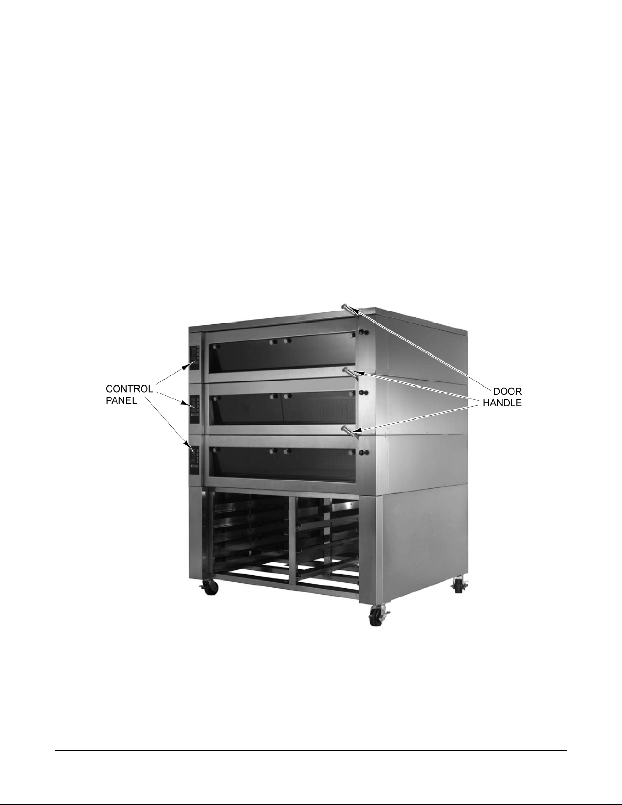
The OV400 & OV401 Series Deck Ovens (Fig. 1) are designed and suited for your baking needs. The
deck ovens are available in four sizes, with up to four individual decks. They are produced with quality
workmanship and material. Proper installation, usage and maintenance of the ovens will result in years
of satisfactory performance.
It is suggested that you thoroughly read this manual and carefully follow the instructions provided.
Fig. 1
– 3 –
Page 4

INSTALLATION
The OV400 & OV401 Series Deck Ovens require some assembly and must be installed by authorized
Bakery Systems trained service technicians.
UNPACKING
This oven was inspected before leaving the factory. The transportation company assumes full responsibility
for safe delivery upon acceptance of the shipment. Immediately after unpacking, check for possible shipping
damage. If the oven is found to be damaged, save the packaging material and contact the carrier within
15 days of delivery.
Carefully unpack the oven and place in a work-accessible area as near to its fi nal installed position as
possible. Verify all packaging material has been removed from the interior of each deck. Remove protective
covering from exterior surfaces prior to placing oven in its fi nal location.
Prior to installation, verify that the electrical and the water service agrees with the specifi cations on the
oven data plate and in this manual.
INSTALLATION CODES AND STANDARDS
In the United States, the Deck Oven must be installed in accordance with:
1. State and local codes.
2. National Electrical Code (ANSI/NFPA No.70, latest edition) available from the National Fire Protection
Association, Batterymarch Park, Quincy, MA 02269.
In Canada, the Deck Oven must be installed in accordance with:
1. Local codes.
2. Canadian Electrical Code (CSA C22.2 No.3, latest edition) available from the Canadian Standards
Association, 5060 Spectrum Way, Mississauga, Ontario, Canada L4W 5N6.
LOCATION
Allow space for operating the oven. The oven requires approximately 6
the vent piping. Do not obstruct the ventilation ports on the sides or back of the oven. To prevent heat
accumulation, 1" clearance is required from any wall. The oven must be installed on an approved stand.
Minimum clearance of 42" must be provided in front of the oven so the oven can be pulled forward for
servicing.
WATER REQUIREMENTS
As with all steam related products, water fi ltration and regular fi lter replacements, coupled with
routine deliming, are required. Your local Service offi ce can recommend a water treatment system to meet
the needs of your local water conditions. Contact your local Service representative for water treatment
offerings.
1
/2" from the back of the oven for
Proper water quality can improve the taste of the food prepared in the oven, reduce liming and extend
equipment life. Local water conditions vary from one location to another. The recommended proper water
treatment for effective and effi cient use of this equipment will also vary depending on the local water conditions.
Ask your municipal water supplier for details about your local water supply prior to installation.
– 4 –
Page 5
WATER REQUIREMENTS (CONT.)
Recommended water hardness is 2.0 to 6.0 grains of hardness per gallon with pH from 7.0 to 8.0. Chlorides
must not exceed 30 parts per million. Water hardness above 6.0 grains per gallon should be treated by
a water conditioner (water softener and/or in-line water treatment). Water hardness below 4.0 grains per
gallon may also require a water treatment system to reduce potential corrosion. Water treatment has
been shown to reduce costs associated with machine cleaning, reduce deliming and reduce corrosion of
metallic surfaces.
PLUMBING CONNECTIONS
Water and waste piping and connections shall comply with the International Plumbing Code 2003,
International Code Council (ICC), or to the Uniform Plumbing Code 2003, International Association of
Plumbing and Mechanical Offi cials (IAPMO).
Plumbing connections must comply with applicable sanitary, safety and plumbing
codes and provide adequate backfl ow protection to comply with applicable federal, state and local
codes.
Connect the cold water supply to the
3
/8" NPT connection located at the rear of the oven. Water supply should
have a pressure of 20 to 80 psi. The oven is supplied with a fl ow regulator which must be installed.
DRAIN CONNECTIONS
In order to avoid any back pressure in the oven, do not connect solidly to any drain. Drain
connections from each deck to the collector box must be high temperature hose.
Connect the
1
/2" drain connection from each deck to the collector box on the deck oven stand. A condensate
drain line must also be run from the lower vent elbow to the collector box. Route the drain line from the
collector box to a fl oor drain. An air gap is provided by the collector box. No air gap required at fl oor
drain.
ELECTRICAL CONNECTIONS
NOTE: The oven must be installed with the provided lanyard securely attached to the stand and to the
wall. Verify that all connections are long enough so that the oven can be pulled forward to the extent of
the lanyard without straining any connections.
Electrical and grounding connections must comply with the applicable portions of
the National Electrical Code and/or other local electrical codes.
Disconnect the electrical power to the unit and follow lockout / tagout
procedures.
ELECTRICAL DATA (Per Deck)
Model Voltage Total Heater kW Line L1 Line L2 Line L3
OV401N 208-240 4.1 - 5.5 11.6 - 13.4 10.9 - 12.6 11.6 - 13.4
OV400N 208-240 5.6 - 7.4 14.7 - 17.0 17.0 - 19.6 14.7 - 17.0
OV401W 208-240 6.9 - 9.2 19.1 - 22.0 19.1 - 22.0 19.1 - 22.0
OV400W
208 10.7 28.1 32.5 28.1
208-240 9.2 - 12.2 24.0 - 27.7 28.6 - 33.0 24.0 - 27.7
VENT HOOD
Some local codes may require the oven to be located under an exhaust hood. Information on the construction
and installation of ventilating hoods may be obtained from Vapor Removal from Cooking Equipment, NFPA
Standard No. 96 (latest edition).
– 5 –
Page 6

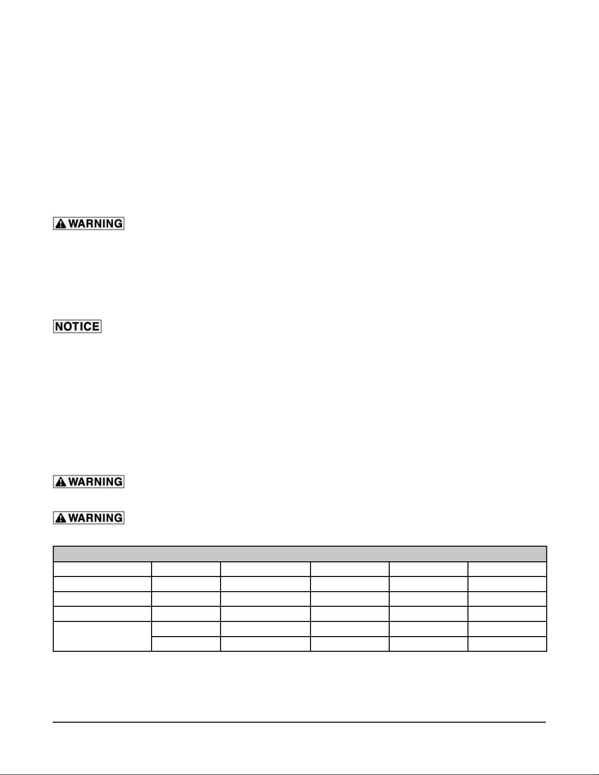
BEFORE FIRST USE
Before using the oven for the fi rst time, when new stones are installed, or if the stones have been cleaned
with water, the baking stones need to be slowly "baked in" prior to start-up. Use the following chart as a
guide for the fi rst start-up to properly season the baking stones.
FOR PANERA CONTROLS
Parameter Step 1 Step 2 Step 3 Step 4 Step 5
Heat
Top Setting 99 99 99 99 99
Bottom Setting
Baking Time 30 Minutes 30 Minutes 30 Minutes 30 Minutes 30 Minutes
Steam None None None None None
Steam Vent Open Open Open Open Open
Parameter Step 1 Step 2 Step 3 Step 4 Step 5
Top Heat
Bottom Heat
Baking Time 30 Minutes 30 Minutes 30 Minutes 30 Minutes 30 Minutes
Steam None None None None None
Steam Vent Open Open Open Open Open
150°F 250°F 350°F 450°F 550°F
99 99 99 99 99
FOR SDC CONTROLS
150°F 250°F 350°F 450°F 550°F
150°F 250°F 350°F 450°F 550°F
– 6 –
Page 7

DIMENSIONS DIAGRAM
10 3/4"
Nominal
"C"
3 1/2" O.D.
7 7/8"
1 3/4"
14""D"
40" For 1 or 2 Decks
31" For 3 Decks
18" For 4 Decks
2 1/2"
Stand Height
"B"
"A"
"E"
Model A B C D E
OV401N
OV400N 51
OV401W
OV400W 51
1
35
/4" 411/2" 365/8" 263/4"
1
57
/4" 365/8" 263/4"
1
35
/4" 411/2" 601/4" 483/8"
1
57
/4" 601/4" 483/8"
22
38
22
38
– 7 –
Page 8

OPERATION
The oven and its parts are hot. Use care when operating, cleaning or servicing the
oven. The baking compartment contains live steam. Stay clear when opening door.
DOOR OPENING AND CLOSING
To open the door (Fig. 2), pull down on the door
handle slightly to allow steam to escape.
After steam escapes, continue pulling down on the
door handle until the door is fully open.
To close the door (Fig. 2), lift the door with the door
handle until the door closes.
Fig. 2
– 8 –
Page 9

CLEANING
Disconnect the electrical power to the machine and follow lockout / tagout
procedures.
The oven and its parts are hot. Use care when operating, servicing or cleaning the
oven.
DAILY CLEANING
• Always allow the oven to cool before cleaning. Never attempt to cool the oven down with cold
water. Sudden temperature changes could damage the glass or baking stones.
• Use care when cleaning around sensitive interior parts, such as probes and sensors.
• Sweep loose particles off the baking stones. Gently scrape off any hardened material on baking
stone.
• Using a clean cloth moistened in warm, soapy water, wash the interior of the oven cavity. Rinse
with rag moistened with clean water and dry with a clean cloth.
• Clean the door gasket with a soft, clean, damp cloth. This will ensure a long life for the gasket.
• Clean the outside daily with a clean, damp cloth.
• Do not use cleaners containing grit, abrasive materials, bleach, harsh chemicals or chlorinated
cleaners. Do not use steel wool on stainless steel surfaces. Never spray down the oven with water,
steam or power wash.
• Be cautious with new or improved cleaning formulas; use only after being well tested in an
inconspicuous place.
– 9 –
Page 10

WEEKLY CLEANING
Baking Chamber Glass
(OV400N & OV401N Only)
Allow the glass to cool before
cleaning. Cleaning while hot may cause the glass
to shatter.
NOTE: Make sure the glass does not fall when
removing the attaching hardware. Do not use any
scouring or sharp objects to clean the glass.
1. Remove two knurled screws and four washers
from the top glass panel (Fig. 3). Note the
position of the washers.
2. Position the top glass diagonally (Fig. 4) to
remove it from the oven cavity.
3. Clean the glass with a clean cloth moistened
in warm, soapy water. Rinse with clean water
and dry with a clean cloth. Glass cleaners may
also be used.
4. Replace the top glass panel in the oven cavity
with four washers and two knurled screws.
GLASS PANEL
Fig. 3
NOTE: Make sure the washers are in the correct
order. Hand tighten the screws.
Fig. 4
– 10 –
Page 11

Split Glass (OV400W & OV401W Only)
Allow the glass to cool before cleaning. Cleaning while hot may cause the glass to
shatter.
1. With the door glass in the closed position, slide handle (Fig. 5) down off of pawl and open left door
glass.
Fig. 5
2. Clean inside of right door glass (Fig. 6).
3. Close left door glass and slide back handle to engage pawl (Fig. 7).
4. Pull down on handle and open both door glasses (Fig. 7).
Fig. 7
Fig. 6
– 11 –
Page 12

5. Pull back on detent and twist 90 degrees to insert pin into door lever (Fig. 8).
6. Slide handle back to release pawl and close left door glass (Fig. 8).
Fig. 8
7. Clean inside of left door glass (Fig. 9).
Fig. 9
8. Pull handle and open left door glass, then slide back handle and insert pawl (Fig. 10).
9. Pull back on detent and twist 90 degrees to retracted position (Fig. 10).
10. Door is ready for normal operation.
Fig. 10
– 12 –
Page 13

MAINTENANCE
Disconnect the electrical power to the machine and follow lockout / tagout
procedures.
BAKING CHAMBER LAMP REPLACEMENT
NOTE: Do not touch the replacement bulb with your fi ngers. Touching the replacement bulb will shorten
bulb life. Wear gloves when replacing halogen lamps.
1. On the left side of the oven, loosen thumb screw (Fig. 11) and remove lamp cover.
2. Remove thumb screw and lamp holder (Fig. 11) from the oven.
3. Replace with approved 24V, 50W halogen lamp (Fig. 11).
LAMP COVER LAMP HOLDER LAMP
Fig. 11
STEAM GENERATOR
The steam generator in each deck should be de-scaled by an authorized servicer on an annual basis.
Depending on the hardness of the water and the amount of use of the steam generators, more frequent
de-scaling may be required.
SERVICE AND PARTS INFORMATION
Contact your authorized service offi ce for any repairs or adjustments needed on this equipment.
– 13 –
Page 14

TROUBLESHOOTING
PROBLEM POSSIBLE CAUSE CORRECTIVE ACTION
Water is in the
baking chamber
No steaming
no steam
Oven is not
heating up
Chamber not
venting
Oven cannot be
turned on
1. Too much steam (time/quantity)
2. Drain hose obstructed
3. Solenoid valve defective
4. Flow regulator defective
1. Steam ready LED not on
2. Water supply not opened
3. Hose kinked/clamped
4. Solenoid valve defective
5. Hose connection defective
6. Steam pipe or connections scaled
7. Steam button defective
8. Steam elements defective
1. No power to oven
2. Temperature not set
3. High limit tripped
4. Defective heating element(s)
5. Temperature sensor defective
1. Defective linkage to vent
2. Vent obstructed
1. No power to oven
2. Internal fuse FT1 or FT2 defective
3. Defective keyswitch
4. Defective control board
1. Check procedures.
2. Check drain connection.
3. Contact your authorized service offi ce.
4. Contact your authorized service offi ce.
1. Wait for oven to recover.
2. Check water supply.
3. Check hose.
4. Contact your authorized service offi ce.
5. Contact your authorized service offi ce.
6. Contact your authorized service offi ce.
7. Contact your authorized service offi ce.
8. Contact your authorized service offi ce.
1. Check power supply.
2. Check temperature setting.
3. Contact your authorized service offi ce.
4. Contact your authorized service offi ce.
5. Contact your authorized service offi ce.
1. Contact your authorized service offi ce.
2. Contact your authorized service offi ce.
1. Check power supply.
2. Contact your authorized service offi ce.
3. Contact your authorized service offi ce.
4. Contact your authorized service offi ce.
– 14 –
Page 15

NOTES
– 15 –
Page 16

NOTES
FORM 36718 (July 2010) PRINTED IN U.S.A.
– 16 –
 Loading...