

Page 1
Operator & Installation
Manual
MB100 PROOFER/HOLDING CABINET
MB300 PROOFER
Model Number: ___________
Serial Number: ___________
Date of Installation: ___________
Baxter Mfg, a Division of ITW FEG, LLC • 19220 State Route 162 East • Orting, WA 98360-9236
Phone: (360) 893-5554 • Fax: (360) 893-1337
www.baxterbakery.com
FORM 36750 Rev. B (September 2012)
Page 2

TABLE OF CONTENTS
GENERAL ............................................................................................................................................. 3
INSTALLATION ..................................................................................................................................... 3
Assembly ......................................................................................................................................... 3
Unpacking ........................................................................................................................................ 3
Plumbing Connections ..................................................................................................................... 4
Drain Connections ........................................................................................................................... 4
Electrical Connections ..................................................................................................................... 4
Dimensions and Service Connection Diagram ................................................................................ 5
OPERATION .......................................................................................................................................... 6
Proofi ng ........................................................................................................................................... 6
Temperature .................................................................................................................................... 7
Humidity ........................................................................................................................................... 8
Setting the Timer ............................................................................................................................. 9
Starting/Adjusting the Timer ............................................................................................................ 9
Canceling/Stopping the Timer ......................................................................................................... 9
Proofi ng Instructions ...................................................................................................................... 10
Holding Instructions (MB100 Only) ................................................................................................ 10
Shutdown Procedures ................................................................................................................... 10
CLEANING ...........................................................................................................................................11
MAINTENANCE .................................................................................................................................. 12
Service and Parts Information ....................................................................................................... 12
TROUBLESHOOTING ........................................................................................................................ 13
PARAMETER SET-UP MODE ............................................................................................................. 14
©BAXTER MFG, 2012
– 2 –
Page 3

OPERATION AND CARE OF
MB100/MB300 PROOFER
SAVE THESE INSTRUCTIONS
GENERAL
The MB100/MB300 Proofer cabinet proofs racks of dough product under controlled temperatures and
humidity prior to baking. The MB300 Proofer has a 16-pan capacity that accommodates 18" x 26" (45.7
cm x 66 cm) baking trays with 3" (7.6 cm) slide spacing. The MB100 holds 8 pans and can be used as
a holding cabinet. Temperature and humidity can be set independently to meet your particular proofi ng
needs. Air is circulated continuously to provide positive movement from bottom to top, creating a uniform
distribution of warm, moist air.
All MB100/MB300 Proofers have easy-to-clean stainless steel interior and exterior panels with urethane
foam insulation.
The MB100/MB300 Proofers are produced with quality workmanship and material. Proper installation,
usage and maintenance of the proofer will result in years of satisfactory performance.
It is suggested that you thoroughly read this manual and carefully follow the instructions provided.
INSTALLATION
The MB100/MB300 Proofer must be installed by authorized Bakery Systems trained service technicians.
ASSEMBLY
The proofer comes pre-assembled, but requires qualifi ed personnel to install and make connections. The
proofer must be installed with restraining means to guard against transmission of strain to the connector, as
specifi ed by the manufacturer. Adequate means must be provided to limit the movement of the appliance.
UNPACKING
This proofer was inspected before leaving the factory. The transportation company assumes full responsibility
for safe delivery upon acceptance of the shipment. Immediately after unpacking, check for possible shipping
damage. If the proofer is found to be damaged, save the packaging material and contact the carrier within
15 days of delivery.
Carefully unpack the proofer and place in a work-accessible area as near to its fi nal installed position as
possible. Remove protective covering from exterior surfaces prior to placing proofer in fi nal location.
– 3 –
Page 4

PLUMBING CONNECTIONS
Water and waste piping and connections shall comply with the International Plumbing Code 2003,
International Code Council (ICC), or to the Uniform Plumbing Code 2003, International Association of
Plumbing and Mechanical Offi cials (IAPMO).
Plumbing connections must comply with applicable sanitary, safety and plumbing
codes and provide adequate backfl ow protection to comply with applicable federal, state and local
codes.
The proofer should have its own water supply line, separate from the oven.
The proofer water supply should have a hardness of 4 to 6 grains per gallon, pH of 6.5 to 8.0 and chlorides
less than 30 PPM. Water condition outside of these requirements may void the warranty. Please consult
your local water company and/or water condition dealer before installing proofer.
1
Connect the cold water supply to the
/4" NPT incoming water connection located at the rear of the proofer.
Water supply should have a pressure of 30 to 75 psi.
DRAIN CONNECTIONS
1
Connect a
/2" drain line to the 1/2" NPT drain connection on the MB300 (3/8" NPT drain connection on the
MB100) located at the rear of the proofer. Route the drain line to a fl oor drain, allowing a minimum 1" air
gap between the drain line outlet and fl oor drain.
ELECTRICAL CONNECTIONS
Electrical and grounding connections must comply with the applicable portions of
the national electrical code and/or other local electrical codes.
Disconnect the electrical power to the unit and follow lockout / tagout procedures.
Appliances equipped with a fl exible electric supply cord are provided with a
three-prong grounding plug. This plug must be connected into a properly grounded three-prong
receptacle. If the receptacle is not the proper grounding type, contact an electrician. Do not remove
the grounding prong from this plug.
– 4 –
Page 5
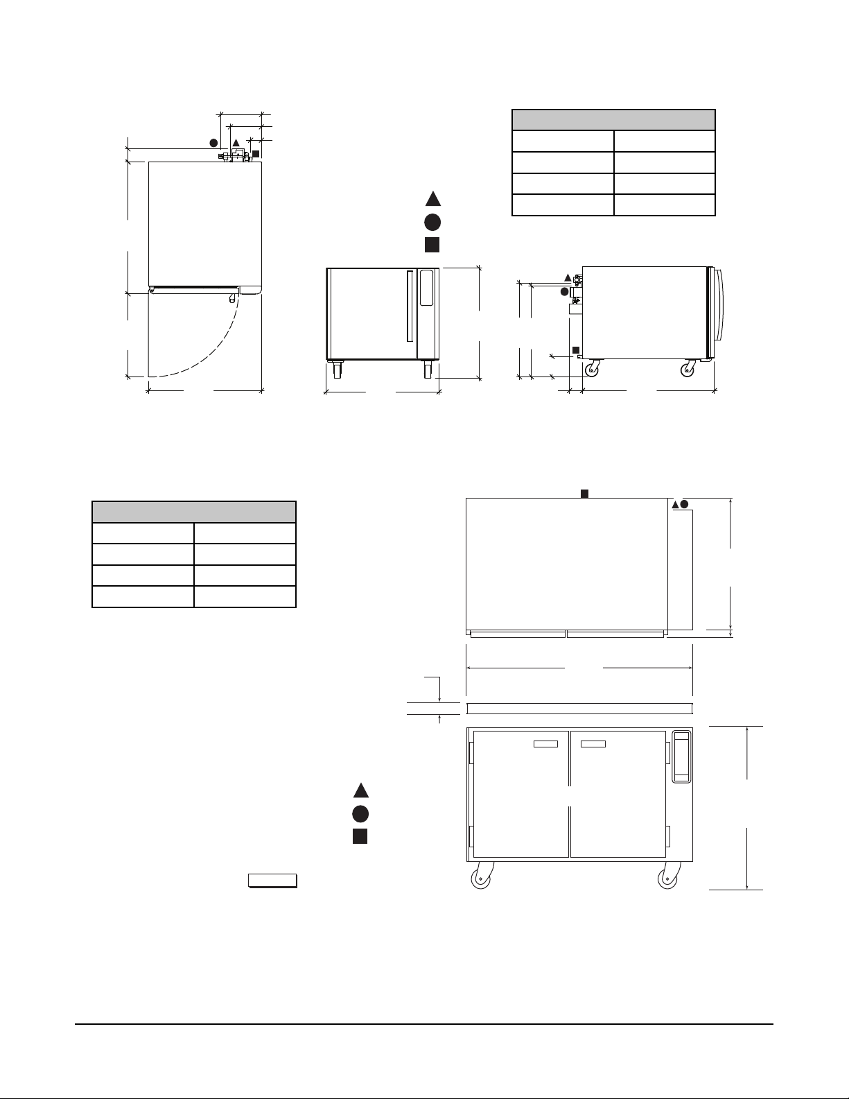
DIMENSIONS AND SERVICE CONNECTION DIAGRAM
4.0"
40.9"
25.7"
35.0"
Electrical Data
Volts 120
Hertz 60
Amps 13
Phase 1
12.6"
9.6"
3.3"
Service Connection Points
Power
Water
Proofer Drain
35.0"
MB100 Proofer/Holding Cabinet
Electrical Data
Volts 120
Hertz 60
Amps 15
Phase 1
Dedicated 20 A circuit breaker and
outlet required.
34.1"
29.1"
28.3"
6.3"
4.0"
40.9"
TOP VIEW
34.61"
(87.9 cm)
Dedicated 20 A circuit breaker and outlet required.
Spacer
Service Connection Points
Power
Water
Proofer Drain
PL-58303
MB300 Proofer
1.37"
(3.5 cm)
48.00"
(121.9 cm)
FRONT VIEW
1.75"
(4.4 cm)
33.00"
(83.8 cm)
– 5 –
Page 6

OPERATION
PROOFING
Controlled temperature and humidity in the proofer promotes yeast fermentation, which generates gas and
causes the dough to rise. Proofi ng takes from 45 to 60 minutes, depending on the product. A temperature
setting of 95°F (35°C) and humidity at 85% are typical but will vary slightly, depending on the product
being proofed. To dry-proof, set the humidity to the lowest setting.
CONTROLS
TEMPERATURE WINDOW - Displays the current or set
temperature. The LED dot will be lit when the heat cycle is
running. The maximum setting is 115°F (46°C).
HUMIDITY WINDOW - Displays the current or set humidity.
The LED dot will be lit when water is being injected into the
proofer cavity.
TIMER WINDOW - Displays the current or set timer. The LED
dot will fl ash to indicate the timer is running.
TIMERS ARROW BUTTON - Press to select a timer (1, 2 or
3). The indicator above the number will be lit to show which
timer is in use.
TEMP BUTTON - Press to adjust or set the temperature.
When the button indicator is lit, the temperature displayed is
the set temperature. When the button indicator is not lit, the
temperature displayed is the current cavity temperature or
set temperature.
HUMIDITY BUTTON - Press to adjust or set the humidity.
When the button indicator is lit, the humidity displayed is the
set humidity. When the button indicator is not lit, the humidity
displayed is the current cavity humidity or set humidity.
TIMER START/STOP BUTTON - Press to select timer function
and to start/stop timer operation. The button indicator is lit
when timer function is entered.
UP or DOWN ARROW - Press to set the temperature, humidity
or timer.
POWER ON/OFF - Press to turn unit on/off.
Fig. 1
– 6 –
Page 7

TEMPERATURE
A
1. Press the POWER ON/OFF button to turn on the
proofer.
2. If the unit is set to display the actual temperature (Fig.
2), the button indicator LED will not be illuminated.
3. If the unit is set to display the set temperature
(Fig. 3), the button indicator LED will be illuminated.
Pressing and holding the TEMP button will display
the actual temperature.
ctual Temperature
Displayed
TEMP Button
LED Not
Illuminated
Fig. 2
Set Temperature
Displayed
TEMP Button
LED Illuminated
Fig. 3
Setting the Temperature
1. Press the TEMP button to adjust the set temperature. The button indicator LED will fl ash and the
set temperature will be displayed for 5 seconds.
2. Press the up or down arrow buttons to adjust the set point while the button indicator LED is
fl ashing.
NOTE: The temperature display will increment by 1° each time the arrow button is pressed. If you
hold down the arrow button for more than 1 second, the temperature display will increment by 5° until
released.
3. After pressing the arrow button, wait 5 seconds to allow the new temperature setting to save.
The indicator LED will stop fl ashing. The TEMP display reverts back to actual or set temperature
mode.
NOTE: If other setups (humidity or timers) are entered within the 5 seconds of idle time, the set temperature
will be saved.
– 7 –
Page 8

HUMIDITY
A
1. If the unit is set to display the actual humidity (Fig. 4),
the button indicator LED will not be illuminated.
2. If the unit is set to display the set humidity (Fig.
5), the button indicator LED will be illuminated.
Pressing and holding the HUM button will display
the actual relative humidity.
ctual
Humidity
Displayed
HUM Button
LED Not
Illuminated
Fig. 4
Set Humidity
Displayed
HUM
Button LED
Illuminated
Fig. 5
Setting the Humidity
1. Press the HUM button to adjust the set humidity. The button indicator LED will fl ash and the set
humidity will be displayed for 5 seconds.
2. Press the up or down arrow buttons to adjust the set point while the button indicator LED is
fl ashing.
NOTE: The humidity display will increment by 1% each time the arrow button is pressed. If you hold
down the arrow button for more than 1 second, the humidity display will increment by 5% until released.
3. After pressing the arrow button, wait 5 seconds to allow the new humidity setting to save. The
indicator LED will stop fl ashing and remain off. The humidity display reverts back to actual or set as
previously selected.
NOTE: If other setups (temperature or timers) are entered within the 5 seconds of idle time, the set
humidity will be saved.
– 8 –
Page 9

SETTING THE TIMER
NOTE: The timer display will initially show "00" in the display window.
1. Press the TIMER START/STOP button to select the timer function. The button indicator LED will
illuminate (Fig. 6) and the timer display will show the current setting.
NOTE: If the TEMP or HUM buttons are pressed while the timer is in setup mode, the timer function will
be canceled.
2. Press the arrow button next to the timers LED indicators to select a timer (1, 2 or 3). The timer display
will show the timer running if the LED dot on the display is on, or the last time set for that timer.
3. Press the up or down arrow buttons to adjust the timer setting. The timer display will show 0 to 60
minutes.
4. Press the TIMER START/STOP button or the arrow button next to the timers LED indicators to save
the set time.
NOTE: The timer setting will also save if no button is pressed for 3 seconds.
STARTING/ADJUSTING THE TIMER
1. After setting the timer, press the TIMER START/STOP
button to start the timer operation. The LED dot on
the timer display will fl ash to indicate the timer is
operating.
2. Press the up or down arrow buttons to adjust the timer
Actual Timer
Displayed
(LED dot flashing)
setting while the timer is in countdown mode.
Timer 1 Selected
NOTE: The timer will pause if the TIMER START/STOP
button is pressed while the timer is running.
3. Press the TIMER START/STOP button to resume timer
running.
TIMER
START/STOP
Button LED
Illuminated
CANCELING/STOPPING THE TIMER
1. Press and hold the down arrow until the timer display
reaches "00". This initiates a stop timer.
NOTE: When the timer completes the time cycle, the buzzer
pulses a short beep and the timer display fl ashes "00".
Fig. 6
2. Press the TIMER START/STOP button to silence the
timer.
NOTE: The temperature or humidity can be changed while the timer is running. See Setting the Temperature
or Setting the Humidity.
– 9 –
Page 10

PROOFING INSTRUCTIONS
1. Press POWER ON/OFF button (Fig. 7). All displays are
now illuminated.
2. Set temperature (as required).
3. Set humidity (as required)
NOTE: Unit will only add humidity 10 minutes after unit has
been turned on. Avoid shutting unit off if used through out
the day. Maximum humidity setting is 95%.
4. Allow cold unit to heat up and balance humidity for 1520 minutes before putting any product in the proofer.
5. Load product using standard 18" x 26" (45.7 cm x 66
cm) pans. Only load as much product as needed for
one oven bake.
6. Set and start timer (as required). (Additional product
may be added to proofer after allowing a lag time of
the typical bake cycle from start of previous batch.)
7. If timer is used, a buzzer will sound and the control
panel will fl ash to indicate the timer has reached "00".
8. Push TIMER START/STOP to silence alarm.
9. Remove product and prepare for oven bake.
HOLDING INSTRUCTIONS (MB100 ONLY)
1. Press POWER ON/OFF button (Fig. 7). All displays are
now illuminated.
2. Set temperature (as required). If Holding is desired,
hold the UP arrow for 5 seconds after it reaches 105
°F and the temperature will jump to 150°F.
Fig. 7
3. Set humidity (as required). The unit will start adding after the fi rst 10 minutes the unit is on. Maximum
humidity setting is 35%.
4. Load product using standard 18" x 26" (45.7 cm x 66 cm) pans.
5. Set and start timer (as required). (Additional product may be added to holding cabinet after allowing
a lag time of the typical bake cycle from start of previous batch.)
6. If timer is used, a buzzer will sound and the control panel will fl ash to indicate the timer has reached
"00".
7. Push TIMER START/STOP to silence alarm.
SHUTDOWN PROCEDURES
1. Remove all product.
2. Press POWER ON/OFF. All displays will not be illuminated.
3. The fan will continue to run for 15-20 minutes after power off. Crack doors during this time frame to
help dry out proofer for MB300.
4. After fan shuts down, the proofer may be cleaned. See Cleaning.
– 10 –
Page 11

CLEANING
1. Using a clean cloth moistened in warm, soapy water, wash the stainless steel interior of the cabinet.
Rinse with clean water and dry with a clean cloth.
2. Clean the outside daily with a clean, damp cloth.
3. Use care when cleaning around sensitive interior parts, such as probes and sensors.
4. Do not use cleaners containing grit, abrasive materials, bleach, harsh chemicals or chlorinated
cleaners. Do not use steel wool on stainless steel surfaces. Never spray down the proofer with water,
steam or power wash.
5. Be cautious with new or improved cleaning formulas; use only after being well tested in an inconspicuous
place.
– 11 –
Page 12

MAINTENANCE
Disconnect the electrical power to the machine and follow lockout / tagout procedures.
SERVICE AND PARTS INFORMATION
Contact your authorized service offi ce for any repairs or adjustments needed on this equipment.
– 12 –
Page 13

TROUBLESHOOTING
PROBLEM POSSIBLE CAUSE CORRECTIVE ACTION
Controller does not turn on after POWER ON/OFF button is
pressed.
Temperature display fl ashes "00". Sensor problem. Contact your authorized service offi ce.
Temperature display fl ashes "Err". Sensor problem. Contact your authorized service offi ce.
Temperature display fl ashes
"OUtP".
Keypad does not respond. Membrane problem. Contact your authorized service offi ce.
Buzzer does not sound when timer
is zero.
Unit will not go to Holding temperature.
1. Unit not plugged in.
2. Control panel fuse blown.
Sensor problem. Contact your authorized service offi ce.
Buzzer problem. Contact your authorized service offi ce.
Unit not set for Holding mode. Check parameter P9 and P14 or contact
1. Check power cord at outlet.
2. Contact your authorized service offi ce.
your authorized service offi ce.
– 13 –
Page 14

PARAMETER SET-UP MODE
FOR SERVICE ONLY
To enter the set-up mode and change parameter setting, the oven should be in the “OFF” mode.
To enable the set-up mode, do the following:
1. Press and hold the “Timer Start/Stop” button and then the power “ON/OFF” button for 5 sec
2. The 2 digit LED humidity window will initially display software version for 2 sec and then displays
the Parameter “P”
3. The 2 digit LED timer window will display parameter number.
4. The 4 digit LED temperature window will display the value.
5. To review the next or previous parameter setting, press either Up or Down arrow button
6. To change the setting of the selected parameter, press the “Timer Start/stop” button then press Up
or Down arrow button to change the value.
7. To save the current setting and selecting another parameter, press the “Timer Start/Stop” button
again
8. To exit the Set-Up Mode, press the “Power ON/OFF” button once.
The PARAMETER NUMBER is displayed in the 4 digit LED temperature display and the values are
displayed in the 3 digit LED timer display.
Each of these values has a PARAMETER NUMBER as follows:
SETUP
NUMBER
P1 Degree Setting This value changes the temperature unit on the
P2 Temperature Offset This number permits an offset, or correction,
P3 Humidity Offset This number permits an offset, or correction,
P4 Minimum Temperature
P5 Maximum Temperature
P6 Minimum Humidity
SETUP ITEM DESCRIPTION DISPLAY
display.
between the temperature read by the probe and
the real proofi ng chamber temperature.
between the humidity read by the probe and the
real proofi ng chamber humidity.
This value acts as a minimum limit for
(Proofi ng Mode)
(Proofi ng Mode)
(Proofi ng Mode)
temperature set point, and the unit will not allow
the operator to set the temperature lower than
this.
This value acts as a maximum limit for
temperature set point, and the unit will not allow
the operator to set the temperature higher than
this.
This value acts as a minimum limit for humidity
set point, and the unit will not allow the operator
to set the humidity lower than this.
F: Fahrenheit (Default)
C: Celsius
Range is +15 to -15°F/C
Default is 0
Range is +15 to -15°F/C
Default is 0
Range is 65 to 115°F
(18 to 46°C)
Default is 65°F (18°C)
Range is 100 to 105°F
(38 to 40°C)
Default is 105°F (40°C)
Range is 35 to 65%
Default is 35
– 14 –
Page 15

SETUP
NUMBER
P7 Maximum Humidity
P8 Temperature Display
P9
(MB100)
P9
(MB300)
P10
(MB100)
P11
(MB100)
P12
(MB100)
P13
(MB100)
P14 Mode Selection This value sets the unit as Proofer only or
SETUP ITEM DESCRIPTION DISPLAY
This value acts as a maximum limit for humidity
(Proofi ng Mode)
Mode
Sensor Mode This value changes the temperature limit on the
Sensor Mode This value changes the temperature limit on the
Minimum Temperature
(Holding Mode)
Maximum Temperature
(Holding Mode)
Minimum Humidity
(Holding Mode)
Maximum Humidity
(Holding Mode)
set point, and the unit will not allow the operator
to set the humidity higher than this.
This value sets what the type of temperature
reading it will display.
controller.
controller.
This value acts as a minimum limit for
temperature set point, and the unit will not allow
the operator to set the temperature lower than
this.
This value acts as a maximum limit for
temperature set point, and the unit will not allow
the operator to set the temperature higher than
this.
This value acts as a minimum limit for humidity
set point, and the unit will not allow the operator
to set the humidity lower than this.
This value acts as a maximum limit for humidity
set point, and the unit will not allow the operator
to set the humidity higher than this.
Proofer/Holder.
Range is 65 to 95%
Default is 90
Actual Mode or Set
Point Mode
Default is Actual
1735 Mode will limit the
controller up to 170°F
(Proof/Hold)
2500 Mode will limit the
controller up to 115°F.
(Proof Only)
Default is 2500
2500 Mode will limit the
controller up to 115°F.
(Proof Only)
Default is 2500
Range is 150 to 155°F
(60 to 66°C)
Default is 150°F (18°C)
Range is 155 to 170°F
(68 to 76°C)
Default is 170°F (76°C)
Range is 15 to 35%
Default is 15
Range is 35 to 50%
Default is 50
ProF = Proofer
Hold = Proofer/Holder MB100 Only
Default is ProF
– 15 –
Page 16

NOTES
FORM 36750 Rev. B (September 2012) PRINTED IN U.S.A.
– 16 –
 Loading...