

Page 1
Operator & Installation
HYBRID CONVECTION OVEN
Manual
HCO100G ML-132510
Model Number: ___________
Serial Number: ___________
Date of Installation: ___________
Baxter Mfg, a Division of ITW FEG, LLC • 19220 State Route 162 East • Orting, WA 98360-9236
Phone: (360) 893-5554 • Fax: (360) 893-1337
www.baxterbakery.com
FORM 36722 (March 2011)
Page 2
IMPORTANT FOR YOUR SAFETY
THIS MANUAL HAS BEEN PREPARED FOR PERSONNEL QUALIFIED TO INSTALL GAS
EQUIPMENT, WHO SHOULD PERFORM THE INITIAL FIELD START-UP AND ADJUSTMENTS
OF THE EQUIPMENT COVERED BY THIS MANUAL.
POST IN A PROMINENT LOCATION THE INSTRUCTIONS TO BE FOLLOWED IN THE EVENT
THE SMELL OF GAS IS DETECTED. THIS INFORMATION CAN BE OBTAINED FROM THE
LOCAL GAS SUPPLIER.
IMPORTANT
IN THE EVENT A GAS ODOR IS DETECTED, SHUT DOWN UNITS
AT MAIN SHUTOFF VALVE AND CONTACT THE LOCAL GAS
COMPANY OR GAS SUPPLIER FOR SERVICE.
FOR YOUR SAFETY
DO NOT STORE OR USE GASOLINE OR OTHER FLAMMABLE
VAPORS OR LIQUIDS IN THE VICINITY OF THIS OR ANY OTHER
APPLIANCE.
IMPROPER INSTALLATION, ADJUSTMENT,
ALTERATION, SERVICE OR MAINTENANCE CAN CAUSE
PROPERTY DAMAGE, INJURY OR DEATH. READ THE
INSTALLATION, OPERATING AND MAINTENANCE INSTRUCTIONS
THOROUGHLY BEFORE INSTALLING OR SERVICING THIS
EQUIPMENT.
IN THE EVENT OF A POWER FAILURE, DO NOT ATTEMPT TO
OPERATE THIS DEVICE.
KEEP AREA AROUND OVEN CLEAR OF COMBUSTIBLES. DO
NOT OBSTRUCT COMBUSTION AND VENTILATION OPENINGS
ON THE OVEN.
©BAXTER MFG, 2011
This manual has been prepared to provide information in accordance with
ANSI Z83.11-2007 for gas equipment.
– 2 –
Page 3

TABLE OF CONTENTS
GENERAL ............................................................................................................................................. 4
INSTALLATION ..................................................................................................................................... 4
Location ........................................................................................................................................... 5
Water Requirements ........................................................................................................................ 5
Installation Codes and Standards .................................................................................................... 5
Assembly ......................................................................................................................................... 6
Gas Connections ............................................................................................................................. 6
Testing the Gas Supply System ....................................................................................................... 6
Ventilation ........................................................................................................................................ 6
Elevation De-Rating ......................................................................................................................... 7
Plumbing Connections ..................................................................................................................... 7
Drain Connections ........................................................................................................................... 7
Electrical Connections ..................................................................................................................... 8
Dimensions Diagram ....................................................................................................................... 9
OPERATION .........................................................................................................................................11
Door Opening And Closing .............................................................................................................11
Controls ..........................................................................................................................................11
Setting the Clock ........................................................................................................................... 13
Setting the Bake Temperature ....................................................................................................... 13
Setting the Bake Timer .................................................................................................................. 13
Setting the Steam Timer ................................................................................................................ 14
Setting the Fan Delay .................................................................................................................... 14
Cool Down Mode ........................................................................................................................... 14
Recipe Designations ...................................................................................................................... 15
Entering Recipes ........................................................................................................................... 15
Using and Reviewing Recipes ....................................................................................................... 15
Customized Operation ................................................................................................................... 15
Basic Operation ............................................................................................................................. 18
CLEANING .......................................................................................................................................... 19
Daily Cleaning ............................................................................................................................... 19
Glass Cleaning .............................................................................................................................. 19
MAINTENANCE .................................................................................................................................. 20
Light Replacement ......................................................................................................................... 20
Service and Parts Information ....................................................................................................... 20
Schematic ...................................................................................................................................... 21
– 3 –
Page 4
INSTALLATION, OPERATION AND CARE OF
HCO HYBRID CONVECTION OVENS
SAVE THESE INSTRUCTIONS
GENERAL
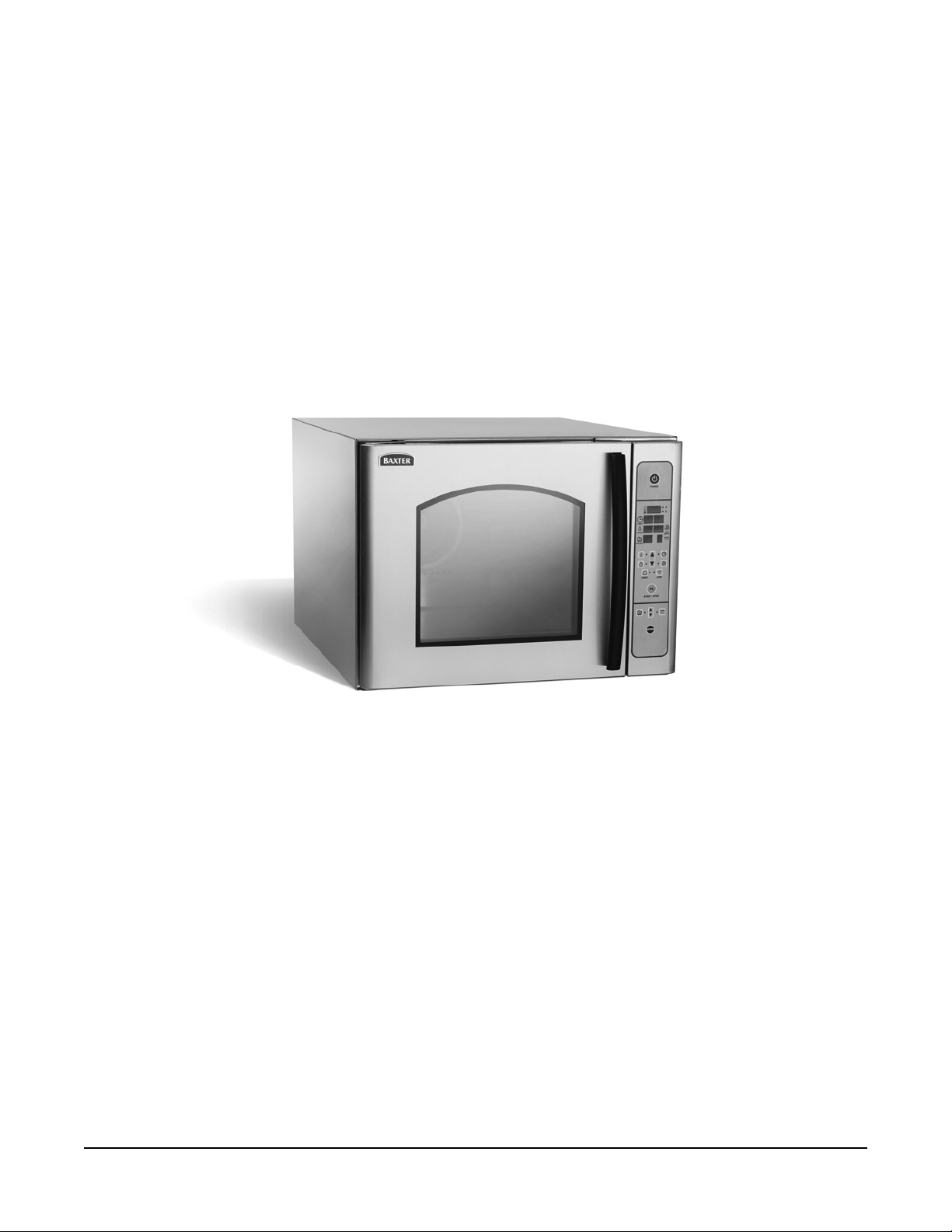
HCO Series Hybrid Convection Ovens (Fig. 1) are designed for your baking needs. There is one size
available, but it is stackable to provide a bank of two independent units. They are produced with quality
workmanship and material. Proper installation, usage and maintenance of the ovens will result in years
of satisfactory performance.
It is suggested that you thoroughly read this manual and carefully follow the instructions provided.
Fig. 1
INSTALLATION
The HCO100G Hybrid Convection Oven comes pre-assembled, but requires qualifi ed personnel to install
and make connections.
UNPACKING
This oven was inspected before leaving the factory. The transportation company assumes full responsibility
for safe delivery upon acceptance of the shipment. Immediately after unpacking, check for possible shipping
damage. If the oven is found to be damaged, save the packaging material and contact the carrier within
15 days of delivery.
Carefully unpack the oven and place in a work-accessible area as near to its fi nal installed position as
possible. Remove protective covering from exterior surfaces prior to placing oven in its fi nal location.
Prior to installation, verify that the electrical and the water service agree with the specifi cations on the
oven data plate and in this manual.
– 4 –
Page 5
LOCATION
The HCO100G Hybrid Convection Oven must have the following minimum clearances to combustibles:
• Top and Sides: 0"
• Back 1" from motor
The oven must be installed on a noncombustible surface and combustibles may not be stored beneath
the mounting surface.
NOTE: Minimum 24" clearance needed for service access on the right side.
Do not obstruct the fl ow of combustion and ventilation air. Adequate clearance for air openings
into the combustion chamber must be provided. Make sure there is an adequate supply of air in the room
to replace air taken out by the ventilating system.
WATER REQUIREMENTS
As with all steam related products, water fi ltration and regular fi lter replacements, coupled with
routine deliming, are required. Your local Hobart Service offi ce can recommend a water treatment system
to meet the needs of your local water conditions. Contact your local Hobart Service representative for
water treatment offerings.
Proper water quality can improve the taste of the food prepared in the oven, reduce liming and extend
equipment life. Local water conditions vary from one location to another. The recommended proper water
treatment for effective and effi cient use of this equipment will also vary depending on the local water conditions.
Ask your municipal water supplier for details about your local water supply prior to installation.
Recommended water hardness is 2.0 to 6.0 grains of hardness per gallon with pH from 7.0 to 8.0. Chlorides
must not exceed 30 parts per million. Water hardness above 6.0 grains per gallon should be treated by
a water conditioner (water softener and/or in-line water treatment). Water hardness below 4.0 grains per
gallon may also require a water treatment system to reduce potential corrosion. Water treatment has
been shown to reduce costs associated with machine cleaning, reduce deliming and reduce corrosion of
metallic surfaces.
INSTALLATION CODES AND STANDARDS
The oven must be installed in accordance with:
In the United States:
1. State and local codes.
2. National Fuel Gas Code, ANSI-Z223.1 (latest edition). Copies may be obtained from The American
Gas Association, Inc.; 1515 Wilson Blvd.; Arlington, VA 22209.
3. National Electrical Code, ANSI/NFPA-70 (latest edition).
In Canada:
1. Local codes.
2. CAN/CGA-B149.1 Natural Gas Installation Code (latest edition).
3. CAN/CGA-B149.1 National Fuel Gas Code (latest edition), available from The Canadian Gas
Association; 178 Rexdale Blvd.; Etobicoke, Ontario; Canada M9W 1R3.
– 5 –
Page 6
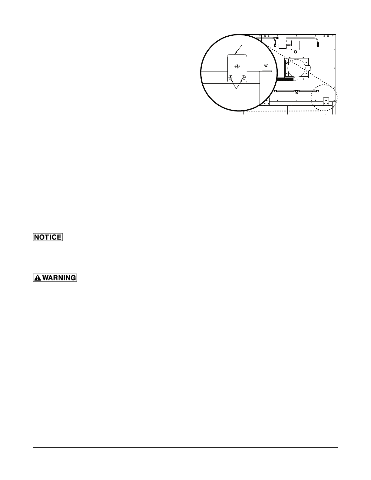
ASSEMBLY
BRACKET
The oven must be installed on a stand, proofer cabinet
or any non-combustible surface.
The oven must be sealed to the stand with an NSFapproved sealant, such as Dow Corning 732 or GE
RTV 108.
Secure the oven to the stand or proofer using the
SCREWS
provided tie down brackets, which mount on the rear
of the oven (Fig. 2).
Oven Mounted on a Stand or Proofer with Caster
Fig. 2
For an appliance equipped with casters:
1) It must be installed with casters supplied.
2) The installation shall be made with a connector that complies with the Standard for Connectors for
Movable Gas Appliances, ANSI Z21.69 or Connectors for Moveable Gas Appliances, CAN/CGA-6.16,
and a quick-disconnect device that complies with the Standard for Quick-Disconnect Devices for
Use With Gas Fuel, ANSI Z21.41, or Quick Disconnect Devices for Use with Gas Fuel, CAN1-6.9.
3) Must be installed with restraining means to guard against transmission of strain to the connector,
as specifi ed by the manufacturer. Adequate means must be provided to limit the movement of the
appliance.
GAS CONNECTIONS
Gas supply connections and any pipe joint compound must be resistant to the action of propane
gases.
The HCO100G is an indirect gas-fi red oven, consisting of a heat exchanger with three independent tubes,
each with a separate in-shot burner rated at 13,333 BTU/hr for a total input of 40,000 BTU/hr.
Prior to lighting, check all joints in the gas supply line for leaks. Use soap and water
solution. Do not use an open fl ame.
TESTING THE GAS SUPPLY SYSTEM
When gas supply pressure exceeds
1
/2 psig (3.45 kPa), the oven and its individual shutoff valve must be
disconnected from the gas supply piping system.
When gas supply pressure is
1
/2 psig (3.45 kPa) or less, the oven should be isolated from the gas supply
system by closing its individual manual shutoff valve.
VENTILATION
Information on the construction and installation of ventilating hoods may be obtained from the standard
for Vapor Removal from Cooking Equipment, NFPA No. 96 (latest edition), available from the National
Fire Protection Association, Batterymarch Park, Quincy, MA 02269.
Indirect Vent (Under Exhaust Hood) - Standard
Locate the oven under an exhaust hood with adequate overhangs and exhaust rates to completely capture
the by-products of combustion discharged from the fl ue. From the termination of the fl ue to the fi lters of
the hood venting system, a minimum clearance of 18" (45.7 cm) must be maintained. The hood exhaust
fan can be electrically interlocked with the oven.
– 6 –
Page 7
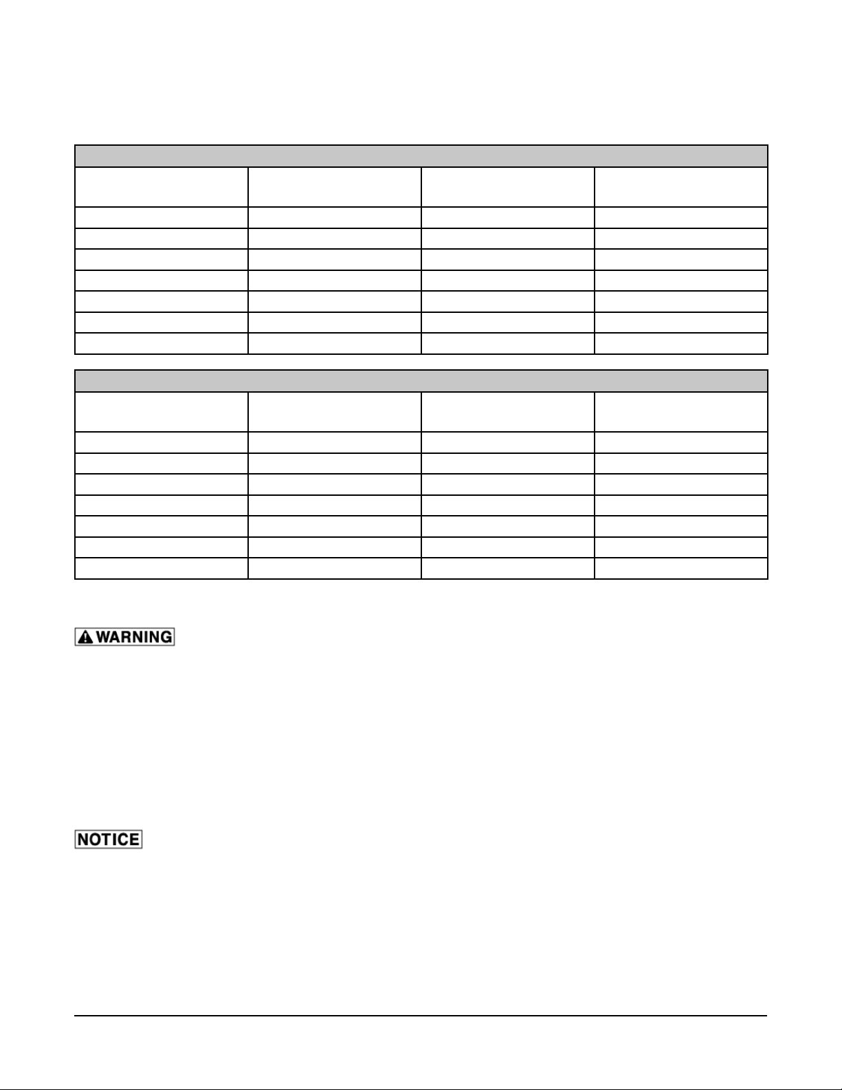
ELEVATION DE-RATING
This unit has been tested to a higher rating to allow safe operation of the unit at 40,000 BTU/hr up to an
elevation of 5000 ft (1524 m). After 5000 ft (1524 m) elevation, the following are the corrected values.
NATURAL GAS
RATING (BTU/HR) MANIFOLD
ORIFICE SIZE
PRESSURE
5000 ft (1524 m) 40,000 3.0 #50 (.070)
5500 ft (1676 m) 39,000 2.9 #50 (.070)
6000 ft (1829 m) 38,000 2.75 #50 (.070)
6500 ft (1981 m) 37,000 2.6 #50 (.070)
7000 ft (2134 m) 36,000 2.5 #50 (.070)
7500 ft (2286 m) 35,000 3.5 #52 (.0635)
8000 ft (2438 m) 34,000 3.25 #52 (.0635)
PROPANE GAS
RATING (BTU/HR) MANIFOLD
ORIFICE SIZE
PRESSURE
5000 ft (1524 m) 40,000 10.5 #58 (.042)
5500 ft (1676 m) 39,000 10.0 #58 (.042)
6000 ft (1829 m) 38,000 9.5 #58 (.042)
6500 ft (1981 m) 37,000 9.0 #58 (.042)
7000 ft (2134 m) 36,000 8.6 #58 (.042)
7500 ft (2286 m) 35,000 8.1 #58 (.042)
8000 ft (2438 m) 34,000 7.6 #58 (.042)
PLUMBING CONNECTIONS
Water and waste piping and connections shall comply with the International Plumbing
Code 2003, International Code Council (ICC), or to the Uniform Plumbing Code 2003, International
Association of Plumbing and Mechanical Offi cials (IAPMO). Plumbing connections must comply
with applicable sanitary, safety and plumbing codes and provide adequate backfl ow protection to
comply with applicable federal, state and local codes.
Connect the cold water supply to the
3
/8" NPT connection located at the rear of the oven. Water supply
should have a pressure of 20 to 80 psi. The oven is supplied with a fl ow regulator which must remain on
the oven.
DRAIN CONNECTIONS
In order to avoid any back pressure in the oven, do not connect solidly to any drain.
Route the drain line to a fl oor drain, allowing a minimum 1" air gap between the drain line outlet and fl oor
drain.
– 7 –
Page 8
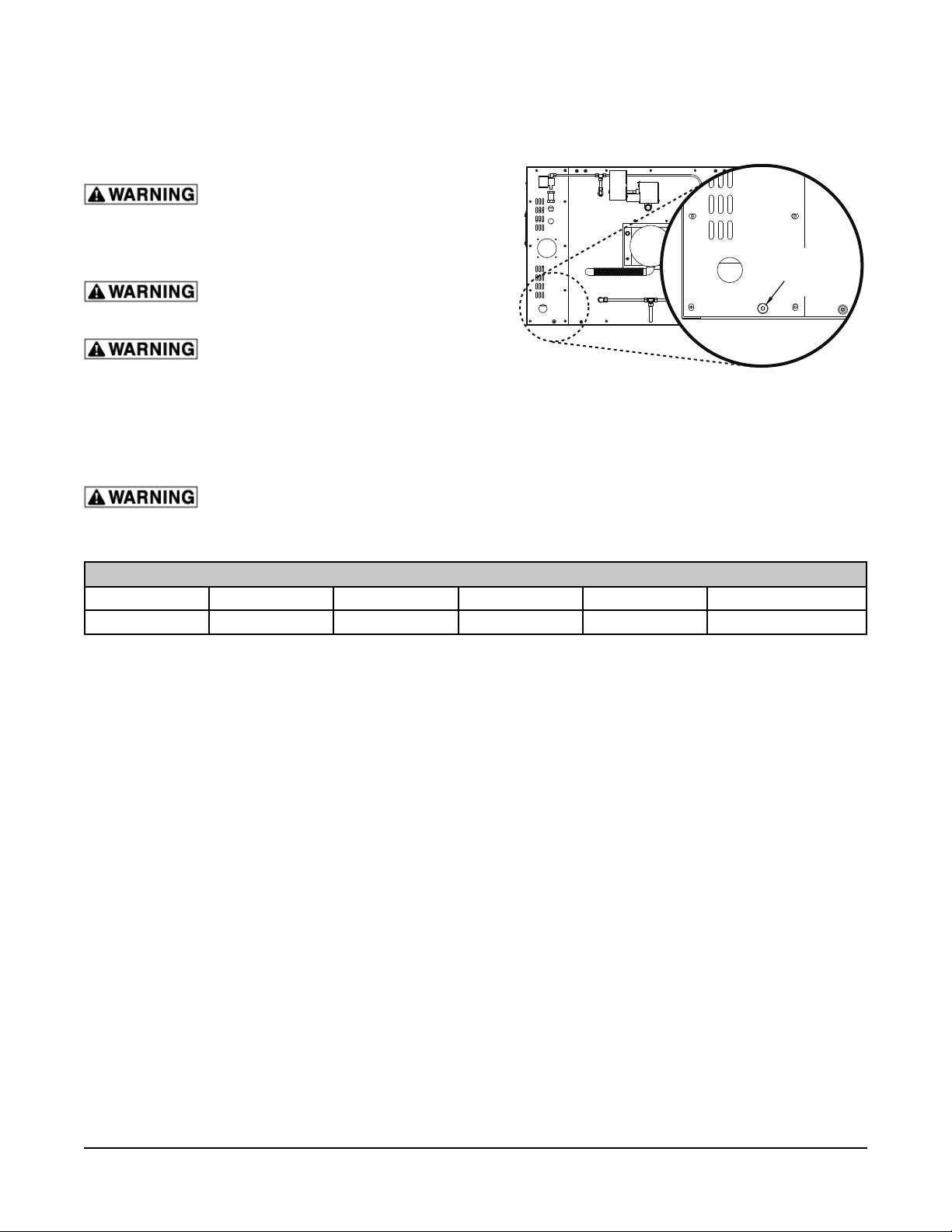
ELECTRICAL CONNECTIONS
NOTE: The oven must be installed with the provided lanyard securely attached to the oven (Fig. 3) and to
the wall. Verify that all connections are long enough so that the oven can be pulled forward to the extent
of the lanyard without straining any connections.
Electrical and grounding connections
must comply with the applicable portions of the
National Electrical Code and/or other local electrical
codes.
Disconnect the electrical power to the
LANYARD
CONNECTION
POINT
unit and follow lockout / tagout procedures.
Appliances equipped with a fl exible
electric supply cord are provided with a three-prong
grounding plug. This plug must be connected into
Fig. 3
a properly grounded three-prong receptacle. If the receptacle is not the proper grounding type,
contact an electrician. Do not remove the grounding prong from this plug.
The wiring diagram is located behind the side service panel on the right side of the oven.
Do not connect the HCO100G gas model to the electrical supply until after gas
connections have been made.
ELECTRICAL DATA (Per Unit)
Model Voltage Phase Amps Motor Max Breaker Size
HCO100G 120 1 6.4
1
/2 Hp.* 15 Amp.
* 5.4 amp included in rating.
– 8 –
Page 9

DIMENSIONS DIAGRAM
STEAM VENT
WATER INLET
3
5
8
N
I
A
2
1
R
0
D
2
L
C
5
27
8
35
MUST BE MOUNTED ON STAND (OPTIONAL)
OR NON-COMBUSTIBLE SURFACE
35
1
3
4
4
3
8
7
7
2
5
8
HCO100G Without Stand Base
412
38
47
5
1
9
2
WATER IN
1
4
3
" WATER
8
CL VENT
7
6
8
15
3
8
INLET
MOTOR
5
3
8
8
6' CORD
120V, 15 A PLUG
7
49
8
5/8" DRAIN
8
6
HCO100G With Stand Base
– 9 –
5
4
3
1
38
2
Page 10

49 7/8 in
35 in
47 1/8 in
n
n
i
8
/
7
9
6
n
i
8
/
7
7
2
i
6
7
5 1/2 in
n
i
4
1
6 3/8 in
HCO100G Double Stacked With Stand Base
– 10 –
Page 11

OPERATION
The oven and its parts are hot. Use care when operating, cleaning or servicing the
oven. The baking compartment contains live steam. Stay clear when opening door.
DOOR OPENING AND CLOSING
To open the door, pull from top of handle (Fig. 4) and
open door slightly to allow steam to escape.
After the steam escapes, open the door to allow
removal of pans.
To close door, push to close.
Fig. 4
CONTROLS
Control Panel Displays
WINDOW DESCRIPTION
TEMPERATURE
DISPLAY
TIMER DISPLAY
TIMER
TIMER DOTS
STEAM TIMER
STEAM
FAN DELAY
FAN
DELAY
RECIPE DISPLAY
R
RECIPE
STEP DISPLAY
STEPS
1 2 3 4
LED in thermometer is the Heat On indicator.
Main display indicates set temperature in normal operation or
actual temperature when called for.
F or C LED indicate temperature in Fahrenheit or Celsius.
Timer dot in left window indicates timer is confi gured for MM:SS.
Timer dot in right window indicates timer is confi gured for HH:MM.
When timer is set for more the 5 minutes, timer will confi gure to
HH:MM.
Will show time of day if oven is off.
Display will show time in seconds for steam. It will count down
when steaming. When complete, it will show "00" except in Food
Service Steam mode.
In Food Service mode, display resets timer for next cycle.
Display will show time in minutes for Fan Delay. It will count down
when selected and period will fl ash. If "00" shows, fan will run if
door closed.
Display will show recipe number selected when used.
Display will show step number of recipe selected and operating if
recipes are being used.
POWER
TIMER
STEAM FAN
R
RECIPE
VENT
R
START / STOP
ENTER
LOW
STEPS
1 2 3 4
DELAY
STEPS
1 2 3 4
– 11 –
Page 12

Control Panel Buttons
BUTTON ACTION DISPLAY
POWER BUTTON
Press to turn oven on or off. Time of day will be displayed in Timer window when
oven is off.
All display widows will show values when oven is on.
PRIMARY
UP/DOWN
BUTTON
SET TEMPERATURE
BUTTON
TIMER BUTTON
STEAM BUTTON
FAN DELAY BUTTON
VENT OPEN BUTTON
LOW FAN BUTTON
START/STOP BUTTON
Press to set selected temperature,
time, steam, or fan delay.
Press to set temperature.
Press and hold for 5 seconds to see
Will change set temperature, set time, steam time,
or fan delay time.
LED is illuminated when in set temperature mode.
LED will fl ash when showing actual temperature.
actual temperature.
Press to set Bake time. LED is illuminated when in Set Timer mode.
Press to set Steam function and
LED is illuminated when in Set Steam Time mode.
time.
Press to set Fan Delay mode. LED will illuminate to show in set mode.
Press to open or close vent on oven. LED will illuminate to show vent is open.
Press to start or stop low fan
LED will illuminate if low fan is operating.
operation. Only active when oven
temperature is below 450 degrees.
Press to Start/Pause or Stop Baking
timer.
If bake time running ":" will fl ash in LED timer and
time will be counting down. If Paused, no ":" fl ash
and time is held.
SECONDARY
UP/DOWN
BUTTON
RECIPE BUTTON
R
STEP BUTTON
STEPS
1 2 3 4
ENTER BUTTON
ENTER
Press to change Recipe or Step
number.
Press to select a recipe number.
Press and hold along with the
Enter button for 5 seconds to enter
programming mode.
Will change set recipe number or step number
depending on selection.
LED will illuminate.
Press Secondary UP/DOWN button to select
program number in recipe display. LED will fl ash
when an empty recipe is displayed.
Press to select the step number. LED will illuminate. Press Secondary Up/Down
button to select step number in step display.
Press to select and enter program
number for operation. Press and hold
for 5 seconds to exit program mode.
If program mode not selected, press
to recall last manual setting before
START/STOP pressed.
– 12 –
Page 13

SETTING THE CLOCK
1. Press the Power button to turn the oven on.
2. Press and hold the Timer button for 5 seconds.
The indicator next to the button will fl ash and
the current time will be displayed in the timer
window.
POWER
TIMER
STEAM FAN
R
RECIPE
DELAY
STEPS
1 2 3 4
POWER
BUTTON
TIMER
WINDOW
TIMER
BUTTON
TIMER
STEAM FAN
R
RECIPE
DELAY
STEPS
1 2 3 4
3. Use the Primary Up/Down Arrow buttons to set
the clock. The time will save after 5 seconds of
inactivity.
NOTE: The clock can be confi gured for 12 or 24
hour display. See Setup Guide.
SETTING THE BAKE TEMPERATURE
1. Press the Temperature button. The current set
temperature will be fl ashing in the temperature
window.
2. Use the Primary Up/Down Arrow buttons to set
the temperature. After 5 seconds, the display
will stop fl ashing and the temperature is set.
The heat on indicator will illuminate.
NOTE: To view the actual oven temperature, press
and hold the Temperature button.
VENT
LOW
START / STOP
R
ENTER
POWER
TIMER
STEAM FAN
R
RECIPE
VENT
LOW
START / STOP
R
ENTER
PRIMARY
STEPS
1 2 3 4
UP/DOWN
BUTTON
HEAT ON
INDICATOR
TEMPERATURE
WINDOW
DELAY
STEPS
1 2 3 4
TEMPERATURE
BUTTON
PRIMARY
STEPS
1 2 3 4
UP/DOWN
BUTTON
VENT
TIMER
STEAM FAN
R
RECIPE
VENT
LOW
START / STOP
LOW
DELAY
STEPS
1 2 3 4
SETTING THE BAKE TIMER
1. Press the Timer button. The current set time
will be fl ashing in the timer window.
2. Use the Primary Up/Down Arrow buttons to set
the bake timer. After 5 seconds, the display will
stop fl ashing and the timer is set.
NOTE: The timer will not start running until the door
is closed and the Start/Stop button is pressed.
NOTE: The decimal point "." is an indicator between
the minutes and seconds. The colon " : " will indicate
the time between hours and minutes. The decimal
point will fl ash when time is counting down and when
time remaining is greater than 5 minutes. When time
remaining is less than 5 minutes, the timer will display
seconds and count down in seconds.
POWER
TIMER
STEAM FAN
R
RECIPE
VENT
LOW
START / STOP
R
ENTER
TIMER
WINDOW
DELAY
STEPS
1 2 3 4
TIMER
BUTTON
PRIMARY
UP/DOWN
BUTTON
STEPS
1 2 3 4
START/STOP
BUTTON
START / STOP
TIMER
STEAM FAN
R
RECIPE
VENT
LOW
START / STOP
DELAY
STEPS
1 2 3 4
– 13 –
Page 14

SETTING THE STEAM TIMER
1. Press the Steam button. The steam time will
be fl ashing in the steam window.
2. Use the Primary Up/Down Arrow buttons to set
the steam timer. After 5 seconds, the display
will stop fl ashing and the steam time is set.
POWER
TIMER
STEAM FAN
R
RECIPE
STEAM TIME
WINDOW
DELAY
STEPS
1 2 3 4
STEAM
BUTTON
TIMER
STEAM FAN
R
RECIPE
DELAY
STEPS
1 2 3 4
NOTE: The maximum set time for steam is 60
seconds. The oven will produce steam for a maximum
of 15 seconds. Any setting over 15 seconds will just
provide additional fan delay. See Setup Guide for
P6. The default is 15 but may be set to a maximum
of 20.
SETTING THE FAN DELAY
1. Press the Fan Delay button. The fan delay time
will be fl ashing in the fan delay window.
2. Use the Primary Up/Down Arrow buttons to
set the fan delay timer. After 5 seconds, the
display will stop fl ashing and the fan delay time
is set.
NOTE: The fan delay timer is set and operates in
1-minute increments.
VENT
LOW
START / STOP
R
ENTER
POWER
TIMER
STEAM FAN
R
RECIPE
VENT
LOW
START / STOP
R
ENTER
PRIMARY
UP/DOWN
BUTTON
STEPS
1 2 3 4
FAN DELAY
WINDOW
DELAY
STEPS
1 2 3 4
FAN DELAY
BUTTON
PRIMARY
UP/DOWN
BUTTON
STEPS
1 2 3 4
VENT
TIMER
STEAM FAN
R
RECIPE
VENT
LOW
START / STOP
LOW
DELAY
STEPS
1 2 3 4
COOL DOWN MODE
The oven has a cool down function which helps cool the
oven quickly to a new lower baking temperature.
1. Set the new lower temperature and open the
door.
NOTE: The new set temperature must be at least
30° lower than the current oven temperature for cool
down mode to operate.
2. Press and hold the Vent button for 3 seconds.
The display windows shut off and the timer
window displays "COOL".
The fan will continue to run until the oven temperature
is within 10° of the new temperature. The buzzer will
sound until the door is closed.
NOTE: To cancel cool down mode, press and hold
the Vent button for 3 seconds OR close the oven
door.
POWER
TIMER
STEAM FAN
R
RECIPE
VENT
LOW
START / STOP
R
ENTER
DELAY
STEPS
1 2 3 4
STEPS
1 2 3 4
TIMER
WINDOW
VENT
BUTTON
START / STOP
TIMER
STEAM FAN
R
RECIPE
VENT
LOW
START / STOP
DELAY
STEPS
1 2 3 4
– 14 –
Page 15

RECIPE DESIGNATIONS
There are two series available for recipe designations. One series is alpha-numeric and uses each letter
followed by numbers 1 to 4. The other series is numeric only which uses 1 through 40.
ENTERING RECIPES
1. Press the Power button to turn the oven on.
DELAY
STEPS
1 2 3 4
STEPS
1 2 3 4
POWER
BUTTON
STEP
WINDOW
RECIPE
WINDOW
STEP
BUTTON
TIMER
STEAM FAN
R
RECIPE
VENT
LOW
DELAY
STEPS
1 2 3 4
2. Press and hold the Recipe button and the Enter
button for 5 seconds. The indicator next to the
recipe button will fl ash.
3. Use the Secondary Up/Down Arrow buttons
to select the recipe designation. The recipe
designation will display in the recipe window.
NOTE: Unused recipe designations will fl ash. Any
used designation will not fl ash but remain solid.
NOTE: The recipe should start on step one.
POWER
TIMER
STEAM FAN
R
RECIPE
VENT
LOW
START / STOP
R
ENTER
4. Set the oven temperature, timer, steam time,
fan delay, vent position, and/or low fan.
5. Press the Enter button.
6. If additional steps are required, press the step
button.
7. Use the Secondary Up/Down Arrow buttons
ENTER
BUTTON
RECIPE
BUTTON
SECONDARY
UP/DOWN
BUTTON
START / STOP
ENTER
STEPS
1 2 3 4
R
to select the step. The step designation will
display in the step window.
8. Set the oven temperature, timer, steam time, fan delay, vent position, and/or low fan as required for
this step.
9. Repeat steps 5 through 8 for each recipe step required.
10. Once the recipe is complete, press and hold the Enter button for 5 seconds.
USING AND REVIEWING RECIPES
1. Press the Recipe button. The indicator next to the recipe button will illuminate.
2. Use the Secondary Up/Down Arrow buttons to select the recipe. If the recipe is programmed, the
recipe will display in the various windows and the various indicators will be illuminated.
3. To review the steps of the recipe, press the Step button and use the Secondary Up/Down Arrow
buttons to review each step.
4. To select a recipe for use, press the Enter button followed by the Start/Stop button.
CUSTOMIZED OPERATION
The Hybrid Convection oven controls have the capability of being customized to fi t your personal needs
using the setup mode.
Before entering the setup mode, read all the instructions to make sure you are completely clear on what
to do. If you need assistance, please call your authorized Bakery Systems service agency.
– 15 –
Page 16

Entering Setup Mode
With the oven off, press and hold the Start/Stop button and the Power button for 5 seconds. The oven is
now in Setup mode and P1 is displayed in the temperature window.
Changing Items in Setup Mode
The number in the temperature window is the setup number. The timer window displays the setup item
(the settings that can be changed).
1. To change the setup number, press the Primary Up/Down Arrow buttons.
2. To make a change in the setup item being displayed, press the Secondary Up/Down Arrow buttons.
To adjust the setting, see Setup Guide. Consult your authorized Bakery Systems service agency for
help with these features.
3. To exit the setup mode, press the Power button.
Setup Guide
SETUP
NUMBER
P1 525°F Maximum temperature set
P2 350°F Preheat temperature This is the default temperature set point when the oven is fi rst turned on. The
P3 50° Minimum temperature set
P4 0 Temperature offset This value permits an offset or correction between the temperature probe and
P5 2° Heat difference hysteresis This value adjusts the temperature difference between the on temperature and
P6 15 Maximum water injection time
P7 °F Temperature units The oven can be set to display temperature in Fahrenheit or Celsius. The values
P8 1 Bake time mode Select 0 for minutes/seconds (MM:SS). Select 1 for hours/minutes (HH:MM).
P9 0 Steam function mode In bakery mode steam system steams only once at the beginning of a bake
P10 0 Auto off timer (in minutes) Time select for oven to go into auto off mode conserving energy. Factory Default
P11 AP Clock operation This selects either 12 hour (AM/PM) or 24 hour real time display.
P12 0 Temperature set back mode Set to 0= set back time disabled. Set to 10 to 180 minutes selects the elapsed
P13 250°F Set back temperature This selects the oven set temperature that the oven will change to when the
DEFAULT
VALUE
SETUP ITEM DESCRIPTION
This is the maximum temperature at which the oven can be set. Range is 50°F
point
point
(in seconds)
to 525°F (10°C to 270°C) 5 degree increments.
preheat temperature cannot be set higher than the value in P1.
Range is 50°F to 525°F (10°C to 270°C) 5 degree increments.
This is the minimum temperature at which the oven can be set. Range is 50°F
to 200°F (10°C to 95°C) 5 degree increments.
the real baking chamber temperature. Range ± 50°F.
off temperature of the heating system from set point. Range is 1 to 20.
Time set is the maximum time (in seconds) that water solenoid is energized
during the Steam Timer operation. Range is 1 to 20.
in parameters P1, P2, & P3 are converted to the new temperature unit when
changed. Any saved recipes will be converted when new unit is selected.
step. In food service mode oven will steam a maximum of 10 seconds at the
beginning of each bake step and will steam a maximum of 10 seconds every
set interval in seconds for the duration of bake time. Select 0 for Bakery mode.
Select 300 to 990 for Food Service mode.
is 0. Must be set between 15 to 120 minutes when P14 is enabled.
AP = 12 hour mode. 24 = 24 hour mode.
time from the last time bake to when the oven goes into set back mode and
lowers the oven set temperature to the value set in P13.
Range is 10 to 180 minutes.
temperature set back time has been exceeded in P12.
Range is 225°F to 300°F (100°C to 150°C).
– 16 –
Page 17

SETUP
NUMBER
P14 0 Auto off mode This selects the auto off mode being enabled or disabled. If enabled the oven
P15 0 Clock display function 0 = Time of day displayed only with oven off. 1 = Time of day displayed with
P16 0 Recipe lockout function This selects recipe lockout function being enabled or disabled. When enabled
P17 0 Fan speed as standard This feature will select whether the oven has high or low speed for normal
DEFAULT
VALUE
SETUP ITEM DESCRIPTION
will automatically turn off after the temperature set back (P12) and auto off (P10)
times have been met. If disabled Auto off time will be inoperable.
0 = Disabled, 1 = Enabled. Time set in P10.
oven off/on, no time in bake time display, and when bake time is complete and
alarm silenced.
operator cannot change an existing recipe when running. If disabled the
operator can make temporary changes to an existing recipe and reverts to
manual operation. 0 = Lockout Disabled, 1 = Lockout Enabled.
operation. If "0" high speed operation is normal and low speed is selected as
required. If low speed operation is selected as normal "1", then low speed fan
will operate as standard for any bakes below 450° and low speed will have to
shut off if high speed operation is required. Low fan speed will not operate at set
points greater than 450°, so high fan speed will default if these set temperatures
are selected.
– 17 –
Page 18

BASIC OPERATION
Startup
When there is power to the oven and the oven is off, the time of day will display in the timer window and
the colon will be fl ashing.
With the door closed, press the Power button to turn the oven on.
• Convection fan turns on.
• Oven lights turn on.
• Heat on indicator is on after 5 seconds.
• Default temperature displayed in the temperature window.
• Timer, steam time, and fan delay display windows display "0".
• Steps window will display "1" and the step indicator will light.
For best baking performance and consistent product results, the following sequence of operation is
recommended.
DELAY
STEPS
1 2 3 4
POWER
BUTTON
TIMER
WINDOW
TIMER
STEAM FAN
R
RECIPE
DELAY
STEPS
1 2 3 4
1. Allow the oven to pre-heat for 30 minutes.
2. Set the baking parameters or use a preprogrammed recipe.
3. Open the oven door and load the product.
4. Push the Start/Stop button while the door is still
POWER
TIMER
STEAM FAN
R
RECIPE
open. The timer window will display "dOOr".
VENT
5. Close the door and the bake cycle starts.
6. When timer reaches "00:00", the display will
fl ash and the buzzer will sound.
7. Press the Start/Stop button to silence the
alarm.
LOW
START / STOP
STEPS
R
1 2 3 4
ENTER
START/STOP
VENT
LOW
BUTTON
START / STOP
NOTE: While the alarm is sounding, press the timer button to add additional time, one press for each
additional minute up to 5 minutes if required.
To clear all settings while oven is timing down, press the recipe button.
– 18 –
Page 19

CLEANING
Disconnect the electrical power to the machine and follow lockout / tagout
procedures.
The oven and its parts are hot. Use care when operating, servicing or cleaning the
oven.
DAILY CLEANING
• Allow oven to cool.
• Use care when cleaning around sensitive interior parts, such as probes and sensors.
• Using a clean cloth moistened in warm, soapy water, wash the interior of the oven cavity. Rinse
with rag moistened with clean water and dry with a clean cloth.
• Clean the door gasket with a soft, clean, damp cloth. This will ensure a long life for the gasket.
• Clean the outside daily with a clean, damp cloth.
• Do not use cleaners containing grit, abrasive materials, bleach, harsh chemicals or chlorinated
cleaners. Do not use steel wool on stainless steel surfaces. Never spray down the oven with water,
steam or power wash.
• Be cautious with new or improved cleaning formulas; use only after being well tested in an
inconspicuous place.
GLASS CLEANING
Allow the glass to cool before
cleaning. Cleaning while hot may cause the glass
to shatter.
1. Open door.
2. Loosen two thumb screws (Fig. 5).
NOTE: Thumb screws are retained to assembly.
3. Swing open inner door glass (Fig. 6).
4. Clean glass.
5. Swing inner door glass back to outer door and
tighten thumb screws (Fig 5).
Fig. 5
– 19 –
Fig. 6
Page 20

MAINTENANCE
Disconnect the electrical power to the machine and follow lockout / tagout
procedures.
The oven and its parts are hot. Use care when operating, servicing or cleaning the
oven.
LIGHT REPLACEMENT
NOTE: Do not touch the replacement bulb with your
fi ngers. Touching the replacement bulb will shorten
bulb life. Wear gloves when replacing halogen
lamps.
NOTE: Use only 5W 12V Halogen bulb.
1. Open door.
2. Remove thumb screws and lens cover from
oven (Fig. 7).
3. Pull at the top of the lens glass until it snaps
out to remove from oven (Fig. 8).
4. Remove old bulb and replace with new bulb.
5. Replace lens glass.
6. Install lens cover with thumb screws.
SERVICE AND PARTS INFORMATION
Contact your authorized service offi ce for any repairs or adjustments needed on this equipment.
Fig. 7
Fig. 8
– 20 –
Page 21

SCHEMATIC
Main Oven Harness (Sheet 1 of 2)
– 21 –
Page 22

Main Oven Harness - Ignition Wiring (Sheet 2 of 2)
– 22 –
Page 23

NOTES
– 23 –
Page 24

NOTES
FORM 36722 (March 2011) PRINTED IN U.S.A.
– 24 –
 Loading...