

Page 1
Service Manual
Flo-Gard@ 6201
Volumetric Infusion Pump
Product Code: 2M8063
07-l g-A1 -688
Baxter Healthcare Corporation
Deerfield, IL 60015, USA
0 Copyright 1992, 1995, Baxter Healthcare Corporation. All rights reserved.
Page 2
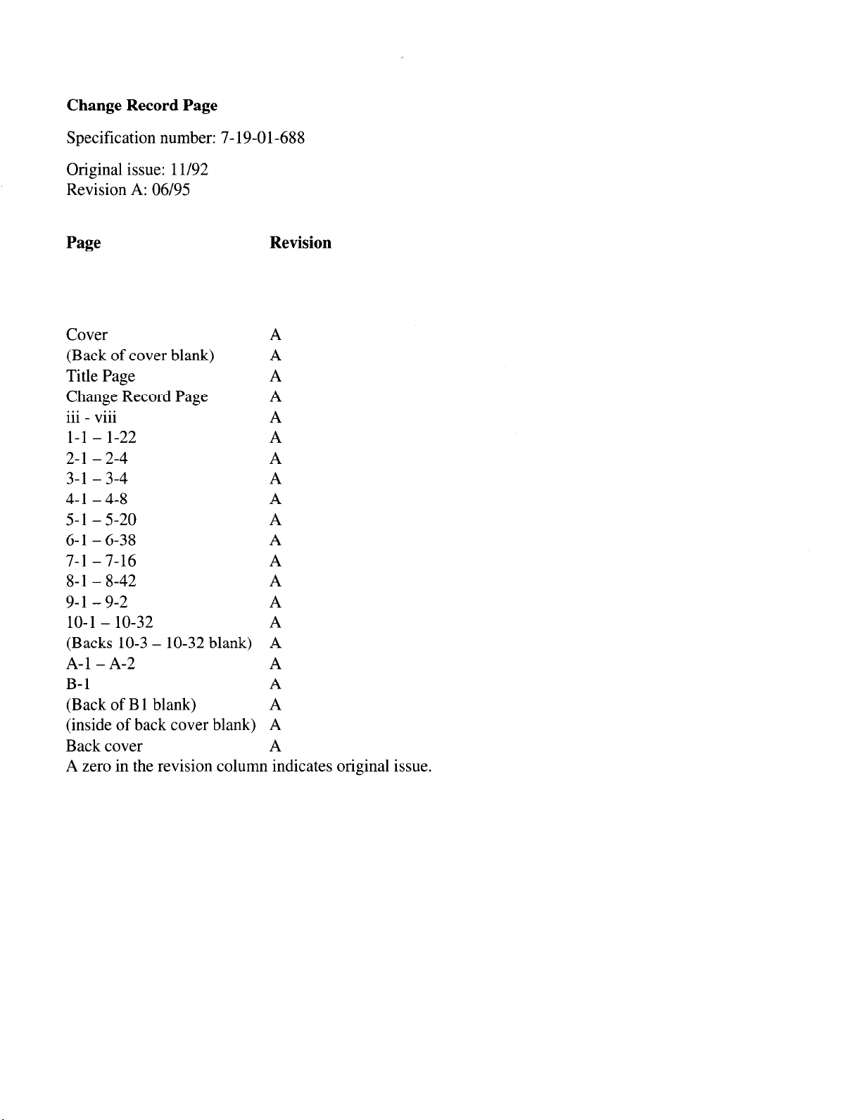
Change Record Page
Specification number: 7- 19-01-688
Original issue: 1 l/92
Revision A: 06/95
Page Revision
Cover
A
(Back of cover blank) A
Title Page A
Change Record Page A
. . . . . .
111 - Vlll
A
l-l - l-22 A
2-l - 2-4 A
3-l - 3-4 A
4-l - 4-8 A
5-l - 5-20 A
6-l - 6-38 A
7-l - 7-16 A
8-1 - 8-42 A
9-l - 9-2 A
10-l - lo-32
A
(Backs 10-3 - lo-32 blank) A
A-l - A-2 A
B-l A
(Back of B 1 blank)
A
(inside of back cover blank) A
Back cover A
A zero in the revision column indicates original issue.
Page 3
Table of Contents
General Description
1.1 Introduction
1.2 Features .............................
1.2.1 Nurse Call ........................
1.3 Technical Specifications .......................
1.4 Controls and Indicators
1.5 Configuration Option Feature
1.5.1 Reviewing the Configuration Option Settings
1.5.2 Modifying the Configuration Option Settings
l.6Alarms .............................
1.7Alerts .............................
Hospital Service Procedures
2.1 Replacement Of Main Power Fuse
2.2 Cleaning .............................
2.3 Battery Charging ..........................
2.4 Preventive Maintenance .......................
Problem Checklist . . . . . . . . . . . . . . . . . . . . . . . . . . . . . 3-1
Theory of Operation
4.1CPUSystem ...........................
4.1.1CPUs
4.1.2 Programmable Timer Module (PTM)
4.1.3 Watchdog Function
4.1.4 I/O Controllers
4.1.5 Multiplexer ........................
4.1.6 Universal Pulse Processor
4.1.7 Communication Controller
4.1.8 Air Sensor Circuit
4.1.9 Occlusion Sensors
4.1.10 Tube Misloading Detector ..................
4.1.11 Slide Clamp Detector
4.1.12 Battery Low Alert/Alarm Detector
4.1.13 Interlock Switch
4.1.14 Panel Lock Circuit
4.1.15 Keypad
4.1.16 Displays .........................
4.1.17MotorDriver
4.1.18 Motor Rotation Detectors ..................
............................
............................
.......................
....................
..........
.......... 1-12
.........................
...................
............................
..........................
..............
.....................
....................... 4-3
..................
..................
.....................
..................... 4-4
....................
..............
......................
..................... 4-5
.........................
.......................
l-l
l-l
l-l
l-2
l-3
l-4
1- 12
1- 12
1-17
1-19
2-1
2-l
2-2
2-3
2-4
4-1
4-l
4-l
4-2
4-2
4-3
4-3
4-4
4-4
4-5
4-5
4-5
4-5
4-6
4-6
4-6
4-6
7-19-Al-688
. . .
111
Page 4
4.2 DC Power Supply and Power Control Circuit . . . . . . . . . . . . . . 4-7
Troubleshooting . . . . . . . . . . . . . . . . . . . . . . . . . .
5.1 Introduction . . . . . . . . . . . . . . . . . . . . . . . .
5.2 Failure Identification Codes . . . . . . . . . . . . . . . . .
5.3 Automatic Test Modes . . . . . . . . . . . . . . . . . . .
5.3.1 Automatic Test Mode 1: Calibration Mode 1 . . . . . . . . . . . 5-2
5.3.2 Automatic Test Mode 2: Calibration Mode 2 . . . . . . .
5.3.3 Automatic Test Mode 3: Manufacturing Test Mode . . . .
5.3.4 Automatic Test Mode 4: Aging Mode . . . . . . . . . .
5.3.5 Automatic Test Mode 5: Display Check Mode . . . . . . . . . . 5-6
5.3.6 Automatic Test Mode 6: Time Information Display Mode . . . . . . 5-6
5.3.7 Automatic Test Mode 7: Pumping Sensor Monitoring Mode .
5.38 Automatic Test Mode 8: Air Sensor Test Mode . . . . . .
5.3.9 Automatic Test Mode 9: Elapsed Time Test Mode . . . . .
5.3.10 Automatic Test Mode 0: Downstream Occlusion Test Mode
5.4 Failure Identification Code Troubleshooting Table . . . . . . . .
5.5 Troubleshooting Chart . . . . . . . . . . . . . . . . . . .
Disassembly and Calibration
......................... 6-1
6.1 Introduction ............................
6.2 Preparation for Maintenance
.....................
6.2.1 Tools and Test Equipment ..................
6.2.2 Recording the Configuration Option Settings
6.3 Disassembly/Reassembly
...................... 6-3
...........
6.3.1 Separation of Front and Rear Housings .............
6.3.2 Separation of Printed Circuit Boards
6.3.3 Replacement of Front Panel Film
6.3.4 Replacement of Pump Head Door Cover
6.3.5 Replacement of Pump Door Latch
6.3.6 Replacement of the Pump Door or Pump Door Assembly
6.3.7 Replacement of Door Latch Pin
6.38 Replacement of Pump Head Assembly
6.3.9 Replacement of Upstream Occlusion Sensor
..............
...............
............ 6-7
............... 6-7
...... 6-8
................
.............
.......... 6-10
6.3.10 Replacement of Downstream Occlusion Sensor Assembly
6.3.11 Air Sensor Assembly Replacement .............
6.3.12 Replacement of (FSR**) Devices for Tube Misloading Sensors .
6.3.13 Replacement of Pump Motor
6.3.14 Replacement of Safety/Slide Clamp Assembly
................ 6-13
......... 6- 15
6.3.15 Spring Retainer Removal .................
6.3.16 Spring Retainer Installation
6.3.17 Replacement of Back Plate
6.3.18 Replacement of Battery
................
................ 6-18
................. 6-18
6.3.19 Replacement of Power Supply Board ............
6.3.20 Replacement of CPU Board
**Interlink Electronics
................
. . . .
5-l
. . . . 5-l
. . . . 5-l
. . . . 5-2
. . . . 5-4
. . . . 5-5
. . . . 5-5
. . . . 5-6
. . . .
. . . .
5-6
5-7
. . . . 5-7
. . . , 5-7
. . . 5-15
6-l
6- 1
6-l
6-2
6-3
6-5
6-6
6-8
6-8
.... 6-10
6- 11
. 6- 12
6-17
6-17
6-19
6-20
iv
7-19-Al-688
Page 5
6.3.21 Replacement of Display Board
6.3.22 Replacement of Sensor Board
6.3.23 Replacement of Audible Alarm/Alert Board
6.3.24 Replacement of Backup Audible Alarm/Alert Board
6.3.25 Replacement of Terminal Board
6.3.26 Replacement of Power Transformer
6.3.27 Replacement of PANEL LOCK Switch
6.3.28 Replacement of Lithium Backup Battery
6.3.29 Tube Guide Shim Installation
6.3.30 LCD Cushion Installation
6.3.3 1 Software Installation
6.4 Calibration
6.4.1 DC Line Voltages
6.4.2 Air Sensor Calibration
6.4.3 Downstream Occlusion Sensor Calibration
6.4.4 Upstream Occlusion Sensor Calibration
6.4.5 Slide Clamp Sensor Calibration
6.4.6 Slide Shaft Sensor Calibration
6.4.7 A/D Convertor Reference Voltage Calibration
...........................
....................
...............
...............
..............
...............
.................
...................
...................
...............
................
..........
.............
...........
...........
...........
............
.........
......
6-20
6-21
6-21
6-22
6-22
6-23
6-23
6-24
6-24
6-26
6-27
6-29
6-29
6-32
6-34
6-35
6-36
6-37
6-38
Checkout
................................
7.1 Introduction
...........................
7.2 Maintenance Flowchart
7.3 Operational Checkout
.......................
7.3.1 Administration Set Placement
7.3.2 Functional Testing
7.3.3 Door Open Alarm Testing
7.3.4 Air Alarm Testing
7.3.5 Drive Defect Test/Occlusion Check
7.3.6 Downstream Occlusion Testing
7.3.7 Upstream Occlusion Testing
7.3.8 Battery Check
7.3.9 Panel Lock Test
7.3.10 Safety Clamp Test
7.3.11 AlarmVolume
7.3.12 Slide Clamp Test
7.3.13 Electrical Safety Tests
7.3.14 Accuracy Tests
Illustrated Parts Breakdown
.........................
Warranty and Service Information
9.1 Warranty Information
9.2 Service Information
9.3 General Information
........................
........................
........................
......................
................
....................
.................
....................
................
......................
.....................
....................
.....................
....................
..................
.....................
......................
.............
...............
. 7-l
. 7-l
. 7-l
. 7-3
. 7-3
. 7-3
. 7-5
. 7-6
. 7-7
. 7-7
. 7-8
. 7-9
7-10
7-10
7-10
7-11
7-12
7-13
8-l
9-1
9- 1
9- 1
9-2
7-i9-~1-688
V
Page 6

Diagrams . . . . . . . . . . . . . . . . . . . . . . . . . . . . . . . . 10-l
Data Sheet, Flo-Gard@ 6201
Volumetric Infusion Pump (2M8063) . . . . . . . . . . . . . . . . . . . . . A-l
Multiple Key Combinations . . . . . . . . . . . . . . . . . . . . . . . . . B-l
vi
7-19-Al-688
Page 7
List of Illustrations
Figure l-l. Front View of Pump .......................
Figure l-2. Pump With Door Open ......................
Figure l-3. Rear View of Pump .......................
Figure 6- 1. Adhesive Application .......................
Figure 6-2. Pressure Application Points
Figure 6-3. LCD Cushion Placement (Inside View) ................
Figure 6-4. Calibration Equipment Setup ....................
Figure 7- 1. Maintenance Flowchart ......................
Figure 8-l. Front Housing Assembly .....................
Figure 8-2. Front Housing Assembly .....................
Figure 8-3. Rear Housing Assembly ......................
Figure 8-4. Rear Housing Assembly ......................
Figure 8-5. Pump Head Door Assembly ....................
Figure 8-6. Pump Base Plate Assembly ....................
Figure 8-7. Pump Base Plate Assembly - Rear ..................
Figure 8-8. Pump Base Plate Assembly ....................
Figure 8-9. Safety/Slide Clamp Assembly ...................
Figure 8-10. Display Bd (Sheet 1 of 2) Component Side .............
Figure 8-10. Display Board (Sheet 2 of 2) Solder Side ..............
Figure 8-l 1. DC Power Supply Board .....................
Figure 8-12. CPU Board (Sheet 1 of 2) Component Side ..............
Figure 8-12. CPU Board (Sheet 2 of 2) Solder Side ...............
Figure 8-13. Sensor Board, Component Side (Sheet 1 of 2) ............
Figure 8-13. Sensor Board, Solder Side (Sheet 2 of 2) ...............
Figure 8- 14. Terminal Board ........................
Figure 8- 15. Backup Buzzer Board ......................
Figure 8-16. Audible Alarm Board ......................
Figure 10-l. System Block Diagram .....................
Figure 10-2. Rear Housing Wiring Diagram ..................
Figure 10-3. Front Housing Wiring Diagram ..................
Figure 10-4. CPU Board Block Diagram
Figure 10-5. Address Decoder for 60K ROM Area (P/O CPU Board) ........
Figure 10-6. Master CPU Block (P/O CPU Board) ................
Figure 10-7. Slave CPU Block (P/O CPU Board) ................
Figure 10-8. UPP, RTC and SRAM Block (P/O CPU Board) ............
Figure 10-9. Alarm Control Circuit (P/O CPU Board)
Figure 10-10. Slave RAM and PTM (P/O CPU Board)
Figure lo- 11. Additional CPU Circuitry ....................
Figure 10-12. Sensor Board Block Diagram ..... ..............
....................
....................
...............
..............
. l-5
. l-9
l-11
6-25
6-25
6-27
6-30
. 7-2
. 8-3
. 8-5
. 8-7
8-9
* 8-13
8-15
8-17
8-19
8-23
8-26
8-27
8-29
8-31
8-32
8-35
8-36
8-37
8-38
8-39
10-3
10-4
10-5
10-6
10-7
10-8
10-9
10-10
10-11
10-12
10-13
10-14
7-19-Al-688
vii
Page 8
Figure lo- 13. Power Supply Control Block (P/O Sensor Board)
Figure 10-14. Occlusion Sensing Block (P/O Sensor Board) ............
........... lo- 15
lo-16
Figure 10-15. Motor Control Block (P/O Sensor Board) .............. lo-17
Figure 10-16. PPI Block #1 (LCD, Keys) (P/O Sensor Board) ........... lo- 18
Figure 10-17. PPI Block#2 (P/O Sensor Board)
................. lo-19
Figure 10-18. Serial Communication Block (P/O Sensor Board) .......... lo-20
Figure lo- 19. Additional Sensor Board Circuitry ................ 10-2 1
Figure 10-20. Display Board ......................... lo-22
Figure 10-21. LCD Drivers (P/O Display Board) ................. lo-23
Figure 10-22. Liquid Crystal Displays (P/O Display Board)
............ lo-24
Figure 10-23. LED Lamps (P/O Display Board) ................. lo-25
Figure 10-24. Audible Alarm Board ...................... lo-26
Figure 10-25. Backup Buzzer Board
Figure 10-26. Terminal Board
........................ lo-28
Figure 10-27. Accessories ..........................
..................... lo-27
lo-29
Figure 10-28. Pumphead Sensors ....................... lo-30
Figure 10-29. Front Panel Key Assignments .................. 10-3 1
Figure 10-30. Power Supply
......................... lo-32
. . .
VI11
7
7-19-Al-688
Page 9
Section
General Description
1 .I Introduction
This manual provides service information for the Flo-Gard@ 6201 Single Channel Volumetric
Infusion Pump (product code 2M8063) for qualified hospital biomedical engineers and service
personnel. See the pump’s Operator’s Manual for detailed operating instructions.
1.2 Features
The Flo-Gard@ 6201 Single Channel Volumetric Infusion Pump is an electromechanical pump
used for the intravenous infusion of liquids at user-selected rates. The pump contains a linear
peristaltic pump head which is programmable and permits infusion of primary and secondary
medication programs. The secondary program automatically switches over to the primary program when secondary infusion is complete (automatic piggybacking).
1
The pump operates on standard 115 VAC 60 Hz electrical power, or on its self-contained re-
chargeable battery. It is portable and has a panel lock-out feature to prevent patient tampering. It
is designed for use with Baxter’s standard administration sets which contain an “s” as the last
character of the code number, for example, 20537s. When infusing solutions through a central
line catheter, sets with a Luer lock adapter should be used. Sets with a Flashball@ device are not
recommended in these applications.
The primary rate of infusion is selectable from 1 to 1,999 mL in 1 mL/hr increments and 1 .O to
99.9 mL/hr in 0.1 mL/hr increments. The secondary rate is selectable from 1 to 999 mL in 1
mL/hr increments and 1 .O to 99.9 mL/hr in 0.1 mL/hr increments. The volume to be infused
(VTBI) is also selectable from 1 to 9,999 mL in 1 mL increments and 1.0 to 99.9 mL in 0.1 mL
increments.
The total volumes infused from primary and secondary programs are added together and accumulated and can be displayed on demand. The primary and secondary VTBIs are independently
decremented and displayed. Upon completion of the primary VTBI, the pump automatically
switches to a keep vein open (KVO) rate. If the pump is started on a secondary rate and VTBI,
the pump will change to the primary rate when the secondary program is completed. The pump
may be stopped at any time by pressing the STOP key unless the pump is in the lockout mode.
7-19-Al-688
l-l
Page 10
General Description
1-2
7-19-Al-688
The Programmed Delivery Profile (PDP) enables manual programming or ramped calculation
(available only on pumps running software versions 1.09 or later) of up to 10 sequential infusion
programs for situations where multiple flow rates are indicated. See the appropriate Operator’s
Manual for additional information.
1.2.1 Nurse Call
The Nurse Call feature is enabled by installing a jumper wire to the Terminal Printed Circuit
Board at the location labeled R421 on the board. When the jumper is connected, the Nurse Call
relay will be energized only during an alarm condition and when the ALARM LED is lit. The relay contact points (normally closed, normally open, and common) are accessible from the COMMUNICATIONS PORT on the rear of the pump (pins 1,4, and 9, respectively). The Nurse Call
feature may be used when the pump is connected to a computer, however, provisions must be
made at the communications port to connect both options simultaneously. Specifications for the
9-pin D connector are listed under Technical Specifications.
Page 11
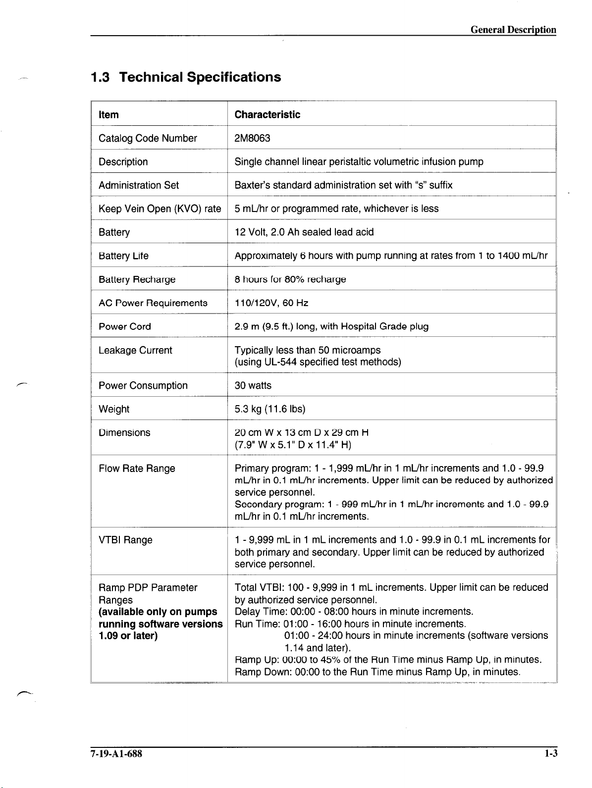
1.3 Technical Specifications
General Description
Item
Catalog Code Number
Description
Administration Set
Keep Vein Open (KVO) rate
Battery
Battery Life
Battery Recharge
AC Power Requirements
Power Cord
Leakage Current
Power Consumption
Characteristic
2M8063
Single channel linear peristaltic volumetric infusion pump
Baxter’s standard administration set with “s” suffix
5 mL/hr or programmed rate, whichever is less
12 Volt, 2.0 Ah sealed lead acid
Approximately 6 hours with pump running at rates from 1 to 1400 mL/hr
8 hours for 80% recharge
110/12OV, 60 Hz
2.9 m (9.5 ft.) long, with Hospital Grade plug
Typically less than 50 microamps
(using UL-544 specified test methods)
30
watts
Weight
Dimensions
Flow Rate Range
VTBI Range
Ramp PDP Parameter
Ranges
(available only on pumps
running software versions
1.09 or later)
-
5.3
kg (11.6 Ibs)
20cmWxl3cmDx29cmH
(7.9” W x 5.1” D x 11.4” H)
Primary program: 1 - 1,999 mL/hr in 1 mL/hr increments and 1 .O - 99.9
mUhr in 0.1 mUhr increments. Upper limit can be reduced by authorized
service personnel.
Secondary program: 1 - 999 mUhr in 1 mUhr increments and 1 .O - 99.9
mUhr in 0.1 mUhr increments.
1 - 9,999 mL in 1 mL increments and 1 .O - 99.9 in 0.1 mL increments for
both primary and secondary. Upper limit can be reduced by authorized
service personnel.
Total VTBI: 100 - 9,999 in 1 mL increments. Upper limit can be reduced
by authorized service personnel.
Delay Time: 0O:OO - 08:OO hours in minute increments.
Run Time: 0l:OO - 16:OO hours in minute increments.
0l:OO - 24:00 hours in minute increments (software versions
1.14 and later).
Ramp Up: 0O:OO to 45% of the Run Time minus Ramp Up, in minutes.
Ramp Down: 0O:OO to the Run Time minus Ramp Up, in minutes.
7-19-Al-688
1-3
Page 12
General Description
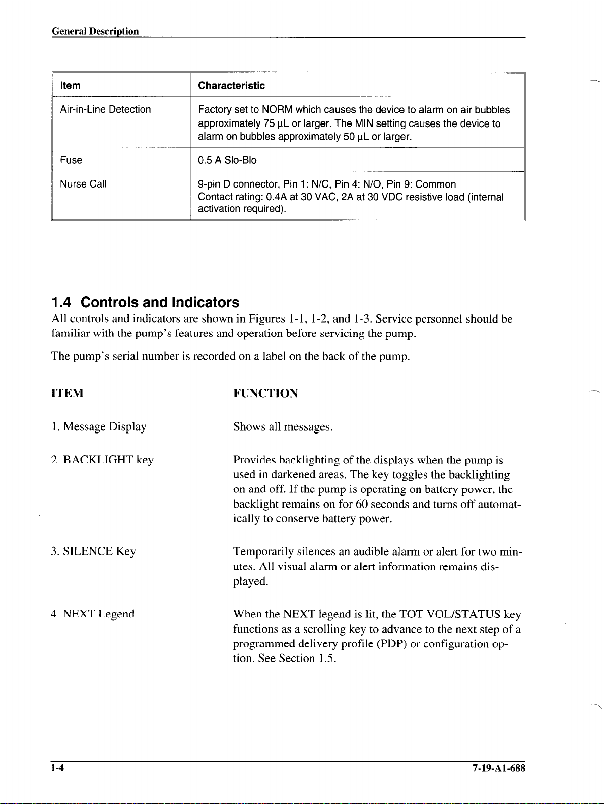
,I Item Characteristic
,
/ Air-in-Line Detection Factory set to NORM which causes the device to alarm on air bubbles
approximately 75 t.rL or larger. The MIN setting causes the device to
alarm on bubbles approximately 50 PL or larger.
I
I Fuse
0.5 A Slo-Blo
1 Nurse Call
I
g-pin D connector, Pin 1: N/C, Pin 4: N/O, Pin 9: Common
i Contact rating: 0.4A at 30 VAC, 2A at 30 VDC resistive load (internal
actrvatron required).
1.4 Controls and Indicators
All controls and indicators are shown in Figures l-l, 1-2, and l-3. Service personnel should be
familiar with the pump’s features and operation before servicing the pump.
The pump’s serial number is recorded on a label on the back of the pump.
ITEM
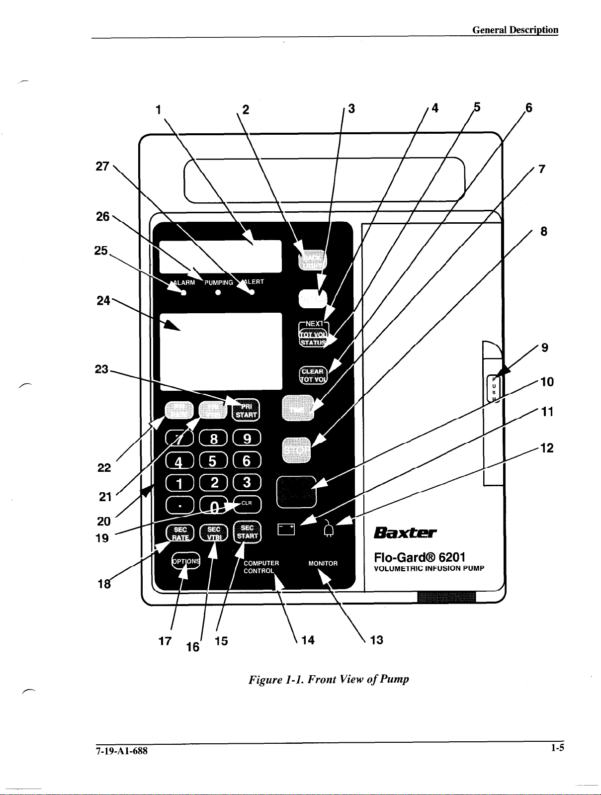
1. Message Display
2. BACKLIGHT key
FUNCTION
Shows all messages.
Provides backlighting of the displays when the pump is
used in darkened areas. The key toggles the backlighting
on and off. If the pump is operating on battery power, the
backlight remains on for 60 seconds and turns off automatically to conserve battery power.
3. SILENCE Key
Temporarily silences an audible alarm or alert for two minutes. All visual alarm or alert information remains displayed.
4. NEXT Legend When the NEXT legend is lit, the TOT VOL/STATUS key
functions as a scrolling key to advance to the next step of a
programmed delivery profile (PDP) or configuration option. See Section 1.5.
1-4
7-19-Al-688
Page 13
General Description
6
/
27
26
25\
24\
23\
7
\
/
\
/
8
9
/
10
/
/
11
22
21 /
20 /
19 ’
1
/
/I2
Flo-Gard@ 6201
VOLUMETRIC INFUSION PUMP
Figure l-l. Front View of Pump
7-19-Al-688
l-5
Page 14
General DescriDtion
1-6
7-19-Al-688
5. TOT VOL/STATUS Key
6. CLEAR TOT VOL Key
7. TIME Key
8. STOP Key
9. Door Latch
Dual-function key. During operation, this key causes total
volume delivered and current settings to display when
pressed. It is also used to select a next step in Review Configuration, Modify Configuration and Programmed Delivery Profile modes. The word “NEXT” above the key is
illuminated when the key is functioning as a NEXT key.
Resets the total volume delivered to zero when the pump is
stopped.
Enters desired time interval for an infusion during VolumeTime or Rate-Time programming.
Stops the pump. The
STOPPED
message appears when the
key is pressed. An alert will sound if pump is stopped for
more than two minutes. Clears all programming alerts
while pump is running.
Opens and closes pump door.
10. ON-OFF/CHARGE Key
11. Battery Icon
12. Plug Icon
13. MONITOR Legend
14. COMPUTER CONTROL
Legend
Turns the pump on and off. The internal battery charger remains on regardless of the ON-OFF/CHARGE key as long
as the pump is plugged in.
Yellow LED, always lit while the pump is operating on battery power.
Green LED, always lit while the pump is plugged in and
the battery is charging.
Lights for at least 2 seconds each time the host computer
communicates with the pump when the pump is in monitor
mode.
Flashes when the pump is initiating communications with
a host computer to enter the computer control mode. It is
constantly illuminated when the pump is in computer control mode.
15. SEC START Key
Starts the delivery of the secondary solution.
16. SEC VTBI Key Allows programming of the secondary VTBI.
Page 15
General Description
17. OPTIONS Key/Legend
18. SEC RATE Key
19. CLR Key
20. Numerical Keypad
21. PRI VTBI Key
22. PRI RATE Key
23. PRI START Key
24. Main Display
Allows the pump to operate in special modes, if enabled.
The OPTIONS legend lights when the key is enabled.
Allows programming of the secondary infusion rate.
Clears any locked in values and programming values currently being entered.
The numerical values for rate, VTBI, and time are entered
with these keys.
Allows programming of the primary VTBI.
Allows programming of the primary infusion rate.
Starts the primary infusion.
Shows rate, volume to be infused (VTBI), and total volume infused for primary and secondary infusion programs.
25. ALARM LED
26. PUMPING LED
27. ALERT LED
Red LED that blinks on and off during an alarm, accompanied by a visual message display and a repeated sequence
of three beeps. An alarm indicates that the pump requires
immediate attention.
Green LED which is constantly lit while pump is running.
Yellow LED which lights during alerts, accompanied by a
message display and a repeated single beep. An alert indicates that the pump needs timely attention.
7-19-Al-688
1-7
Page 16
General Description
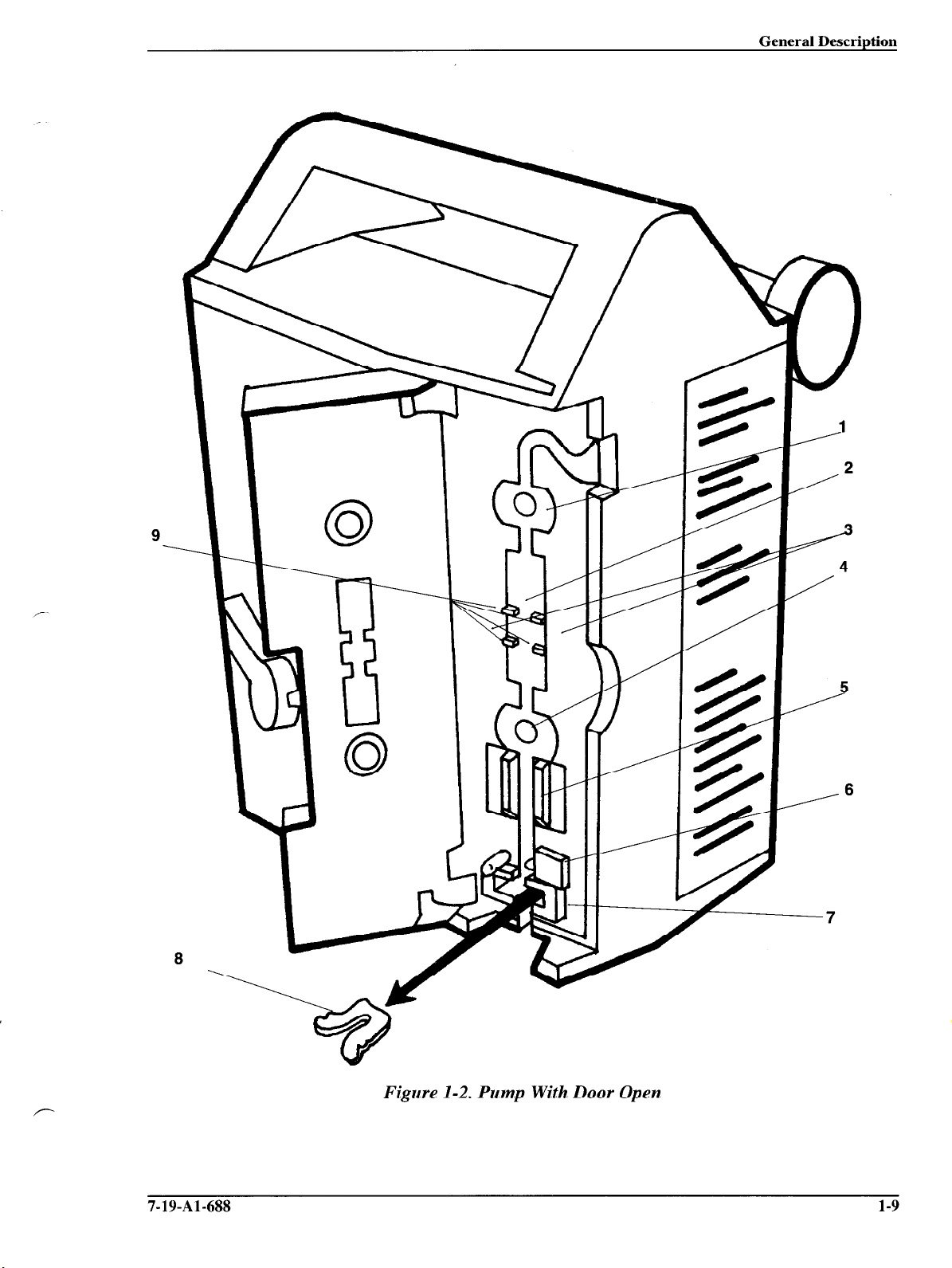
See Figure l-2 for the location of the following items.
1. Upstream Occlusion Sensor
2. Pump Mechanism
3. Tube Misloading Sensor
4. Downstream Occlusion Sensor
5. Air Sensor
6. Safety Clamp
7. Slide Clamp Feature
Detects a complete tubing restriction upstream of the pump.
Linear peristaltic pump mechanism.
Detects misloaded tubing out of the channel guide slots.
Detects a complete tubing restriction downstream of the
pump.
Detects air bubbles in the IV set.
Prevents accidental fluid flow when the IV set is properly
loaded and the pump door is opened.
Provides an additional means of preventing accidental
gravity fluid flow by occluding the tubing in the admini-
stration set with the slide clamp before the set can be re-
moved from the pump. The use of this feature is optional;
when used, the slide clamp must be loaded in the slide
clamp slot. The feature is selectable through the pump’s
configuration options. If alert mode is enabled, the pump
will operate without the slide clamp inserted and the
SERT SLIDECLAMP
message is displayed. An alert tone
IN-
will sound to notify the user that the slide clamp should be
inserted. If the alarm mode is enabled (software versions
1.09 or later), the pump will NOT start and an alarm tone
will sound if the slide clamp is not loaded.
8. Spring Retainer Insert
9. Channel Guide Ridges
1-8
The pump is shipped from the factory with this plastic in-
sert in the slide clamp slot. It prevents damage to the
mechanism during shipment and maintains the proper
spring tension. If your hospital does not plan on using the
slide clamp feature, Baxter recommends that this plastic insert remain in place during use. See Section 6.3.15.
Function as a guide to keep the tubing properly aligned
over the pumping fingers.
7-19-Al-688
Page 17
General Description
9
.
a
Figure 1-2. Pump With Door Open
7-19-Al-688 1-9
Page 18
General Description
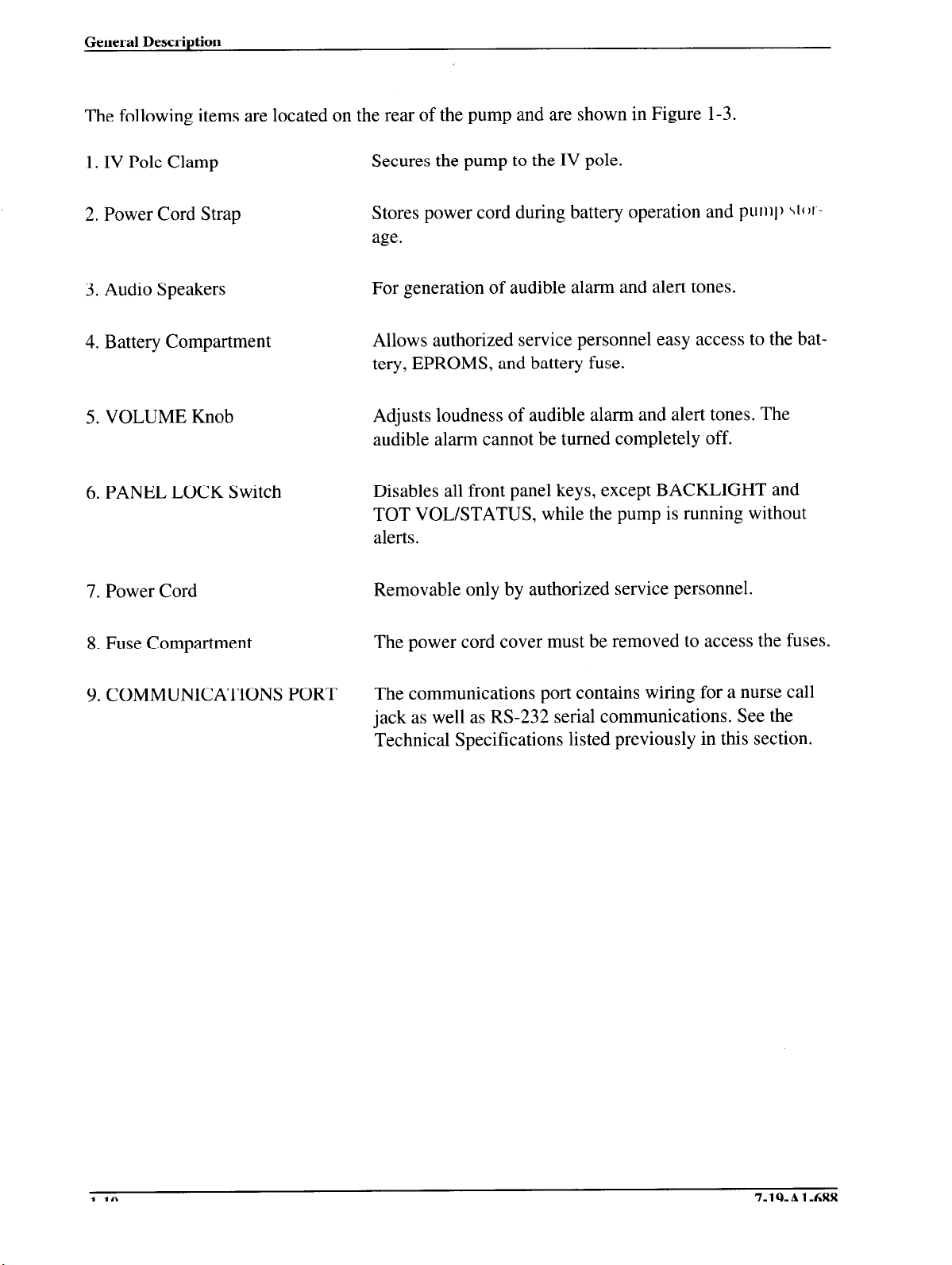
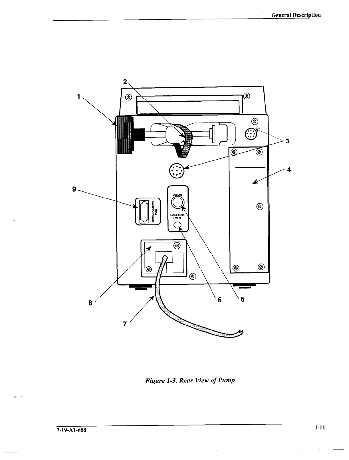
The following items are located on the rear of the pump and are shown in Figure l-3.
1. IV Pole Clamp
2. Power Cord Strap
3. Audio Speakers
4. Battery Compartment
5. VOLUME Knob
6. PANEL LOCK Switch
7. Power Cord
Secures the pump to the IV pole.
Stores power cord during battery operation and pump \t(~i-age.
For generation of audible alarm and alert tones.
Allows authorized service personnel easy access to the battery, EPROMS, and battery fuse.
Adjusts loudness of audible alarm and alert tones. The
audible alarm cannot be turned completely off.
Disables all front panel keys, except BACKLIGHT and
TOT VOL/STATUS, while the pump is running without
alerts.
Removable only by authorized service personnel.
8. Fuse Compartment
9. COMMUNICATIONS PORT
The power cord cover must be removed to access the fuses.
The communications port contains wiring for a nurse call
jack as well as RS-232 serial communications. See the
Technical Specifications listed previously in this section.
l-10
7-19-Al-688
Page 19
1
General Description
_--
\
lo
/=\
::*.-
..-
>
/4
3
7-19-Al-688
a
/
Figure 1-3. Rear View of Pump
l-11
Page 20
General Description
1.5 Configuration Option Feature
This section describes the configuration option feature of the pump, which allows qualified personnel to inspect and/or modify certain pump operating parameters to suit customer requirements.
These parameters and their setting options are shown in Table 1- 1. The factory settings made at
the time of manufacture are also shown in the table.
Note: Although the configuration option data is stored in battery backed-up
RAM, it may be lost if the main battery connector (CN302) is disconnected from the CPU board without turning off the device. The configuration option data is also lost if the lithium backup battery
connector (CN304) is disconnected while the main battery is disconnected. Therefore, we advise that the configuration options be recorded before beginning repair procedures and reset when repairs
are complete.
1.5.1 Reviewing the Configuration Option Settings
To review the configuration option settings, the pump must be powered on and stopped. Press
TIME and TOT VOWSTATUS simultaneously for one second. The message REVlEW
CONFlG
will be displayed in the Message Display. The option description will be displayed in the first
line of the Message Display when the NEXT or SEC START key is pressed, beginning with
CLUSION.
The current setting will be displayed on the second line.
OC-
To view the next setting, press the NEXT or SEC START key. Each press of the NEXT or SEC
START key will cause the pump to advance to the next setting, in the order shown in Table l-l,
starting with Occlusion Alarm Level. To exit the inspection mode, press the STOP key or press
TIME and TOT VOLBTATUS simultaneously.
1.5.2 Modifying the Configuration Option Settings
1. Turn off the pump.
2. While pressing the STOP key and PANEL LOCK switch, press the ON-OFF/CHARGE
key. The following will occur:
a. The
MODIFY CONFIG
message appears in the Message Display.
Note: If the message
LOCKED OUT
is displayed, the configuration option settings can be changed only via computer control. See the Programmer’s Manual for additional information.
1-12 7-19-Al-688
Page 21
General Description
b. The parameter descriptor appears in the first line of the Message Display when the
NEXT or SEC START key is pressed.
c. The current parameter setting appears in the second line of the Message Display.
d. The programming display is blank.
3. Press the NEXT or SEC START key to advance to the desired parameter. The parameters appear in the order shown in Table 1- 1.
4. To change the settings, enter the desired value on the front panel. The selected numeric
value will be displayed in the Primary Rate display until the value is locked in by the
PRI START key, or the next parameter is displayed by pressing the NEXT or SEC
START key.
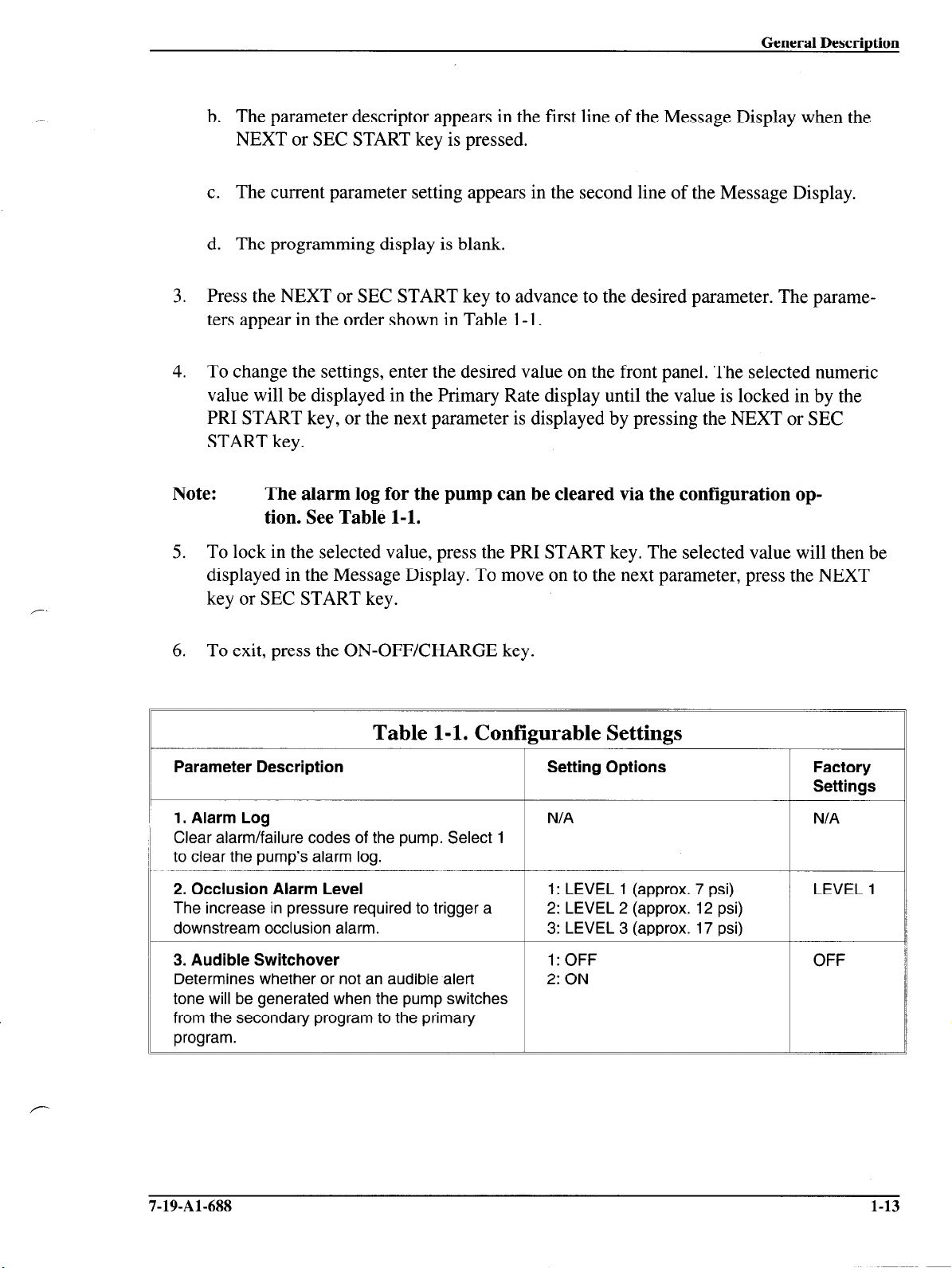
Note: The alarm log for the pump can be cleared via the configuration op-
tion. See Table l-l.
5. To lock in the selected value, press the PRI START key. The selected value will then be
displayed in the Message Display. To move on to the next parameter, press the NEXT
key or SEC START key.
6. To exit, press the ON-OFF/CHARGE key.
Table l-l. Conf
Parameter Description
1. Alarm Log N/A 1 NIA
Clear alarm/failure codes of the pump. Select 1
to clear the pump’s alarm log.
2. Occlusion Alarm Level
The increase in pressure required to trigger a
downstream occlusion alarm.
3. Audible Switchover
Determines whether or not an audible alert
tone will be generated when the pump switches
from the secondary program to the primary
program.
gurable Settings
Setting Options
+
c
1: LEVEL 1 (approx. 7 psi) LEVEL 1
2: LEVEL 2 (approx. 12 psi)
3: LEVEL 3 (approx. 17 psi)
L
1: OFF OFF
2: ON
L
Factory
Settings
7-19-Al-688 1-13
Page 22
General Description
I
Parameter Description
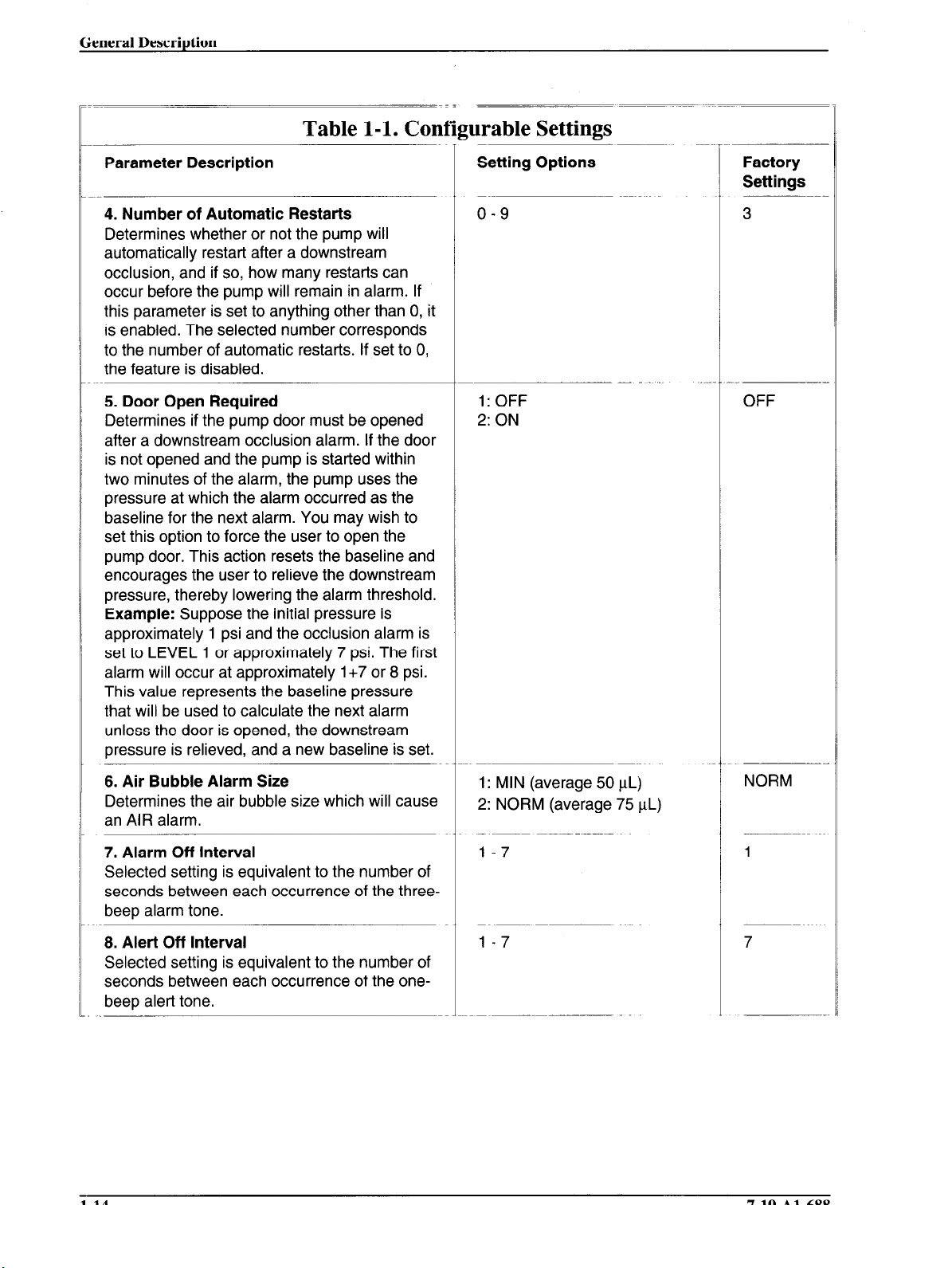
4. Number of Automatic Restarts
Determines whether or not the pump will
automatically restart after a downstream
occlusion, and if so, how many restarts can
occur before the pump will remain in alarm. If
this parameter is set to anything other than 0, it
is enabled. The selected number corresponds
to the number of automatic restarts. If set to 0,
the feature is disabled.
5. Door Open Required
Determines if the pump door must be opened
after a downstream occlusion alarm. If the door
is not opened and the pump is started within
two minutes of the alarm, the pump uses the
pressure at which the alarm occurred as the
baseline for the next alarm. You may wish to
set this option to force the user to open the
pump door. This action resets the baseline and
encourages the user to relieve the downstream
pressure, thereby lowering the alarm threshold.
Example: Suppose the initial pressure is
approximately 1 psi and the occlusion alarm is
set to LEVEL 1 or approximately 7 psi. The first
alarm will occur at approximately 1+7 or 8 psi.
This value represents the baseline pressure
that will be used to calculate the next alarm
unless the door is opened, the downstream
pressure is relieved, and a new baseline is set.
Table l-l. Cod
yrable Settings
Setting Options
o-9
1: OFF
2: ON
Factory
Settings
3
OFF
6. Air Bubble Alarm Size
Determines the air bubble size which will cause
an AIR alarm.
7. Alarm Off Interval
Selected setting is equivalent to the number of
seconds between each occurrence of the threebeep alarm tone.
8. Alert Off Interval
Selected setting is equivalent to the number of
seconds between each occurrence of the onebeep alert tone.
1-14 7-19-Al-688
1: MIN (average 50 uL)
2: NORM (average 75 uL)
l-7
l-7
NORM
1
7
Page 23
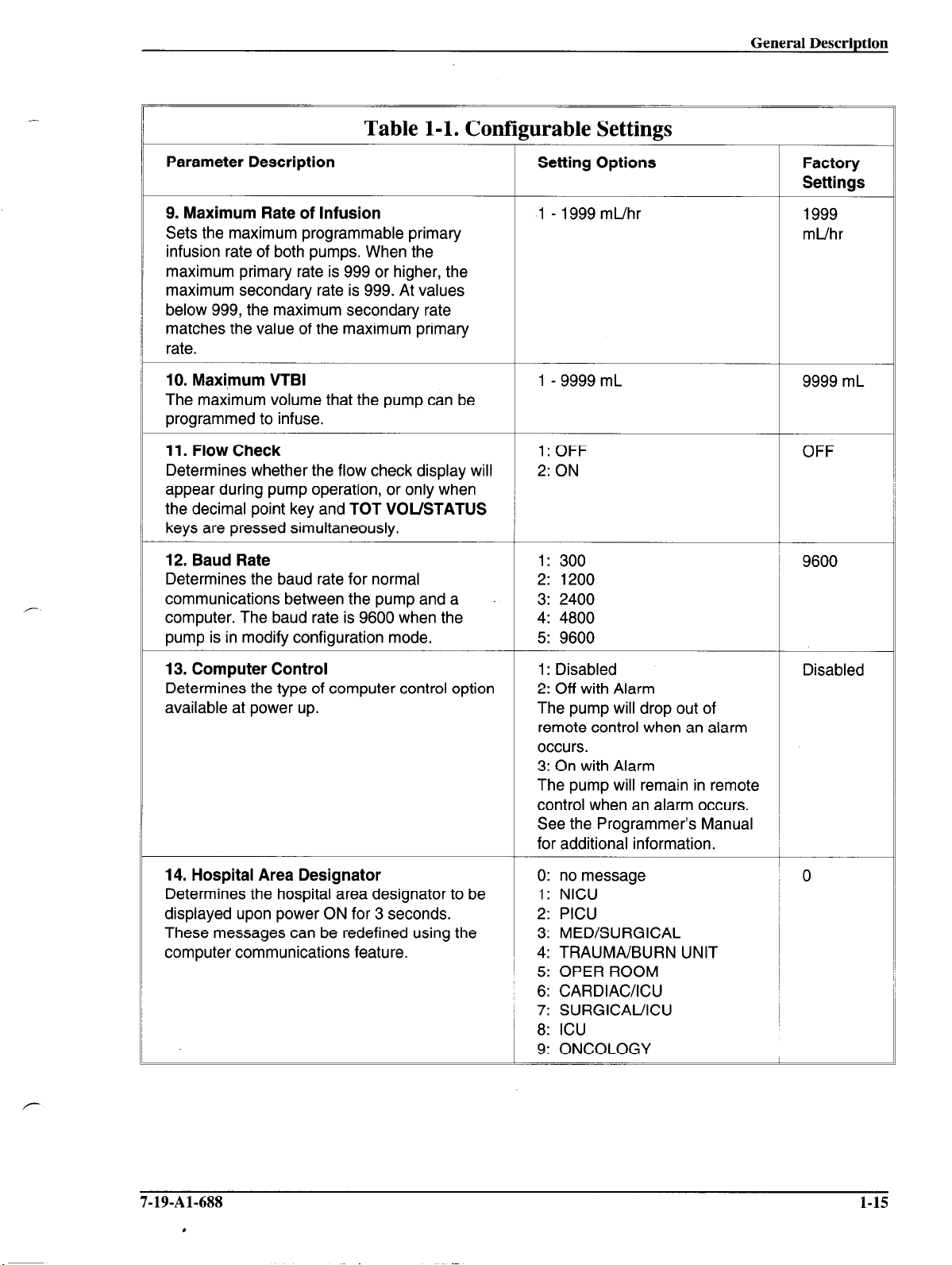
Table l-l. Configurable Settings
Parameter Description Setting Options Factory
Settings
9. Maximum Rate of Infusion
Sets the maximum programmable primary
infusion rate of both pumps. When the
maximum primary rate is 999 or higher, the
maximum secondary rate is 999. At values
below 999, the maximum secondary rate
matches the value of the maximum primary
rate.
10. Maximum VTBI
The maximum volume that the pump can be
programmed to infuse.
11. Flow Check
Determines whether the flow check display will 2: ON
appear during pump operation, or only when
the decimal point key and TOT VOUSTATUS
keys are pressed simultaneously.
12. Baud Rate
Determines the baud rate for normal
communications between the pump and a
computer. The baud rate is 9600 when the
pump is in modify configuration mode.
13. Computer Control
Determines the type of computer control option
available at power up.
1 - 1999 mL/hr 1999
1 - 9999 mL 9999 mL
1: OFF
’
1: 300
2: 1200
3: 2400
4: 4800
5: 9600
1: Disabled
2: Off with Alarm
The pump will drop out of
remote control when an alarm
occurs.
3: On with Alarm
The pump will remain in remote
control when an alarm occurs.
See the Programmer’s Manual
for additional information.
mL/hr
OFF
~ 9600
Disabled
14. Hospital Area Designator
Determines the hospital area designator to be
displayed upon power ON for 3 seconds.
These messages can be redefined using the
computer communications feature.
7-19-Al-688
.
0: no message ~ 0
1: NICU
2: PICU
3: MEDKURGICAL
4: TRAUMA/BURN UNIT
~ 5: OPER ROOM
6: CARDIACXCU
1 7: SURGICAUICU
/ 8: ICU
9: ONCOLOGY
1
1-15
Page 24
General Description
Table l-l. Con
Parameter Description
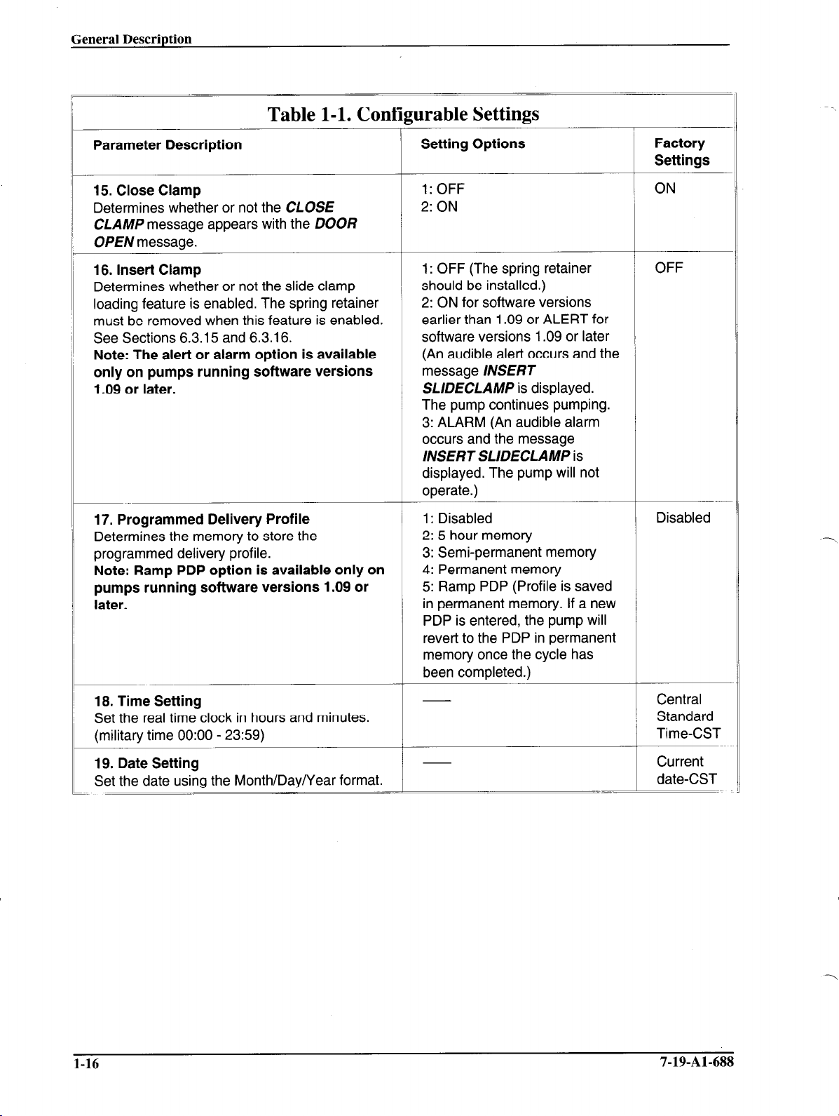
15. Close Clamp
Determines whether or not the CLOSE
CLAMP message appears with the DOOR
OPEN message.
16. Insert Clamp
Determines whether or not the slide clamp
loading feature is enabled. The spring retainer
must be removed when this feature is enabled.
See Sections 6.3.15 and 6.3.16.
Note: The alert or alarm option is available
only on pumps running software versions
1.09 or later.
[urable Settings
Setting Options
1: OFF
2: ON
-1: OFF (The spring retainer
should be installed.)
2: ON for software versions
earlier than 1.09 or ALERT for
software versions 1.09 or later
(An audible alert occurs and the
message INSERT
SLIDECLAMP is displayed.
The pump continues pumping.
3: ALARM (An audible alarm
occurs and the message
INSERT SLIDECLAMP is
displayed. The pump will not
operate.)
-\
Factory
Settings
ON
OFF
17. Programmed Delivery Profile
Determines the memory to store the
programmed delivery profile.
Note: Ramp PDP option is available only on
pumps running software versions 1.09 or
later.
18. Time Setting
Set the real time clock in hours and minutes.
(military time 0O:OO - 2359)
19. Date Setting
Set the date using the Month/Day/Year format.
-
1: Disabled
2: 5 hour memory
3: Semi-permanent memory
4: Permanent memory
5: Ramp PDP (Profile is saved
in permanent memory. If a new
PDP is entered, the pump will
revert to the PDP in permanent
memory once the cycle has
been completed.)
-
Disabled
Central
Standard
Time-CST
Current
date-CST
1-16
7-19-Al-688
Page 25
General Description
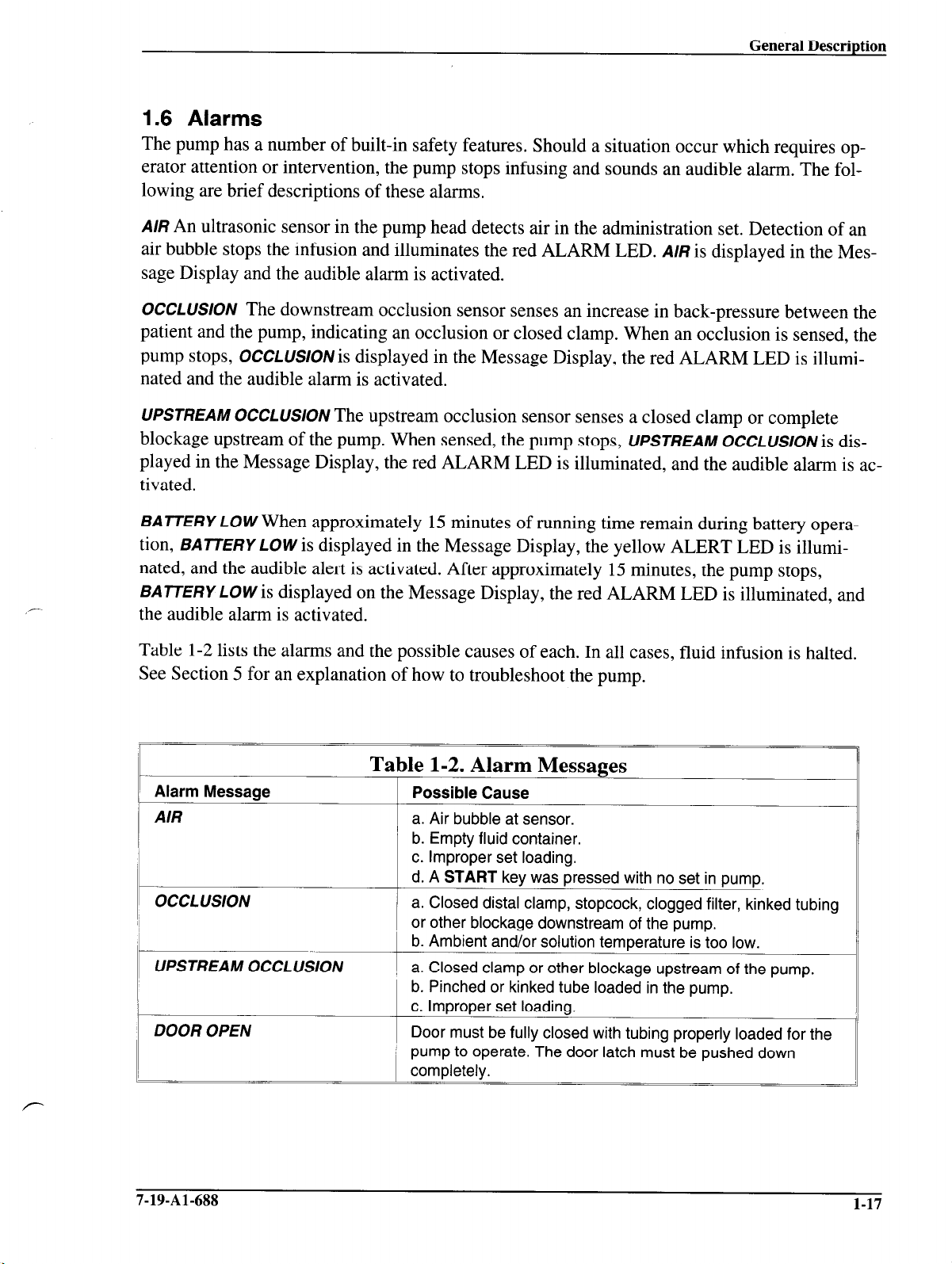
1.6 Alarms
The pump has a number of built-in safety features. Should a situation occur which requires operator attention or intervention, the pump stops infusing and sounds an audible alarm. The following are brief descriptions of these alarms.
A/R
An ultrasonic sensor in the pump head detects air in the administration set. Detection of an
air bubble stops the infusion and illuminates the red ALARM LED.
sage Display and the audible alarm is activated.
AIR
is displayed in the Mes-
OCCLUSlON
The downstream occlusion sensor senses an increase in back-pressure between the
patient and the pump, indicating an occlusion or closed clamp. When an occlusion is sensed, the
pump stops,
OCCLUSION
is displayed in the Message Display, the red ALARM LED is illumi-
nated and the audible alarm is activated.
UPSTREAM OCCLUSloN
blockage upstream of the pump. When sensed, the pump stops,
The upstream occlusion sensor senses a closed clamp or complete
UPSTREAM OCCLUSION
is dis-
played in the Message Display, the red ALARM LED is illuminated, and the audible alarm is ac-
tivated.
BATTERY LOW
tion,
BATTERY LOW
When approximately 15 minutes of running time remain during battery opera-
is displayed in the Message Display, the yellow ALERT LED is illumi-
nated, and the audible alert is activated. After approximately 15 minutes, the pump stops,
BATTERY LOW
is displayed on the Message Display, the red ALARM LED is illuminated, and
the audible alarm is activated.
Table l-2 lists the alarms and the possible causes of each. In all cases, fluid infusion is halted.
See Section 5 for an explanation of how to troubleshoot the pump.
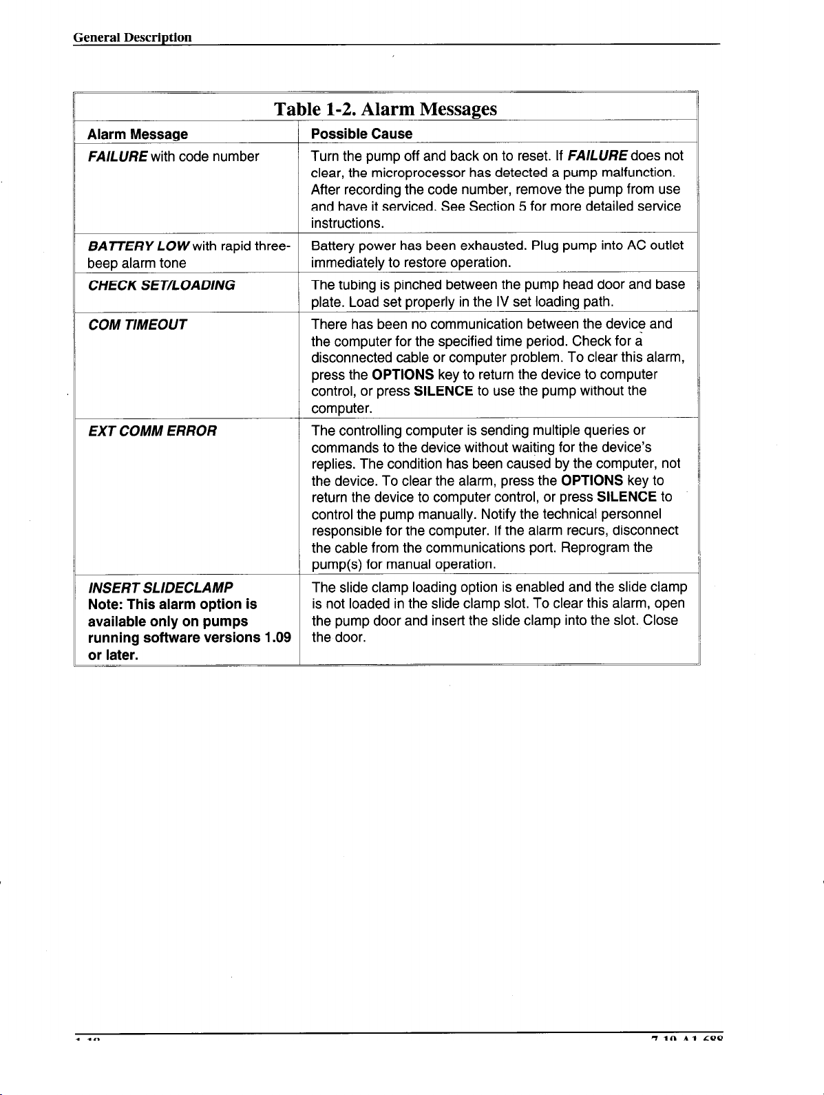
Table 1-2. Alarm Messages
Alarm Message
AIR
bCCLUSlON
j
Possible Cause
, a. Air bubble at sensor.
b. Empty fluid container.
c. Improper set loading.
d. A START key was pressed with no set in pump.
a. Closed distal clamp, stopcock, clogged filter, kinked tubing
or other blockage downstream of the pump.
b. Ambient and/or solution temperature is too low.
a. Closed clamp or other blockage upstream of the pump.
b. Pinched or kinked tube loaded in the pump.
7-19-Al-688 1-17
Page 26
General Description
Table 1-2. Alarm Messages
Alarm Message
FAlLURE with code number
BATTERY LOWwith rapid threebeep alarm tone
CHECK SET/LOADING The tubing is pinched between the pump head door and base
COM TIMEOUT
EXT COMM ERROR
INSERT SLIDECLAMP
Note: This alarm option is
available only on pumps
running software versions 1.09
or later.
Possible Cause
Turn the pump off and back on to reset. If FAILURE does not
clear, the microprocessor has detected a pump malfunction.
After recording the code number, remove the pump from use
and have it serviced. See Section 5 for more detailed service
instructions.
Battery power has been exhausted. Plug pump into AC outlet
immediately to restore operation.
plate. Load set properly in the IV set loading path.
There has been no communication between the device and
the computer for the specified time period. Check for a
disconnected cable or computer problem. To clear this alarm,
press the OPTIONS key to return the device to computer
control, or press SILENCE to use the pump without the
computer.
The controlling computer is sending multiple queries or
commands to the device without waiting for the device’s
replies. The condition has been caused by the computer, not
the device. To clear the alarm, press the OPTIONS key to
return the device to computer control, or press
control the pump manually. Notify the technical personnel
responsible for the computer. If the alarm recurs, disconnect
the cable from the communications port. Reprogram the
pump(s) for manual operation.
The slide clamp loading option is enabled and the slide clamp
is not loaded in the slide clamp slot. To clear this alarm, open
the pump door and insert the slide clamp into the slot. Close
the door.
SILENCE
to
1-18
7-19-Al-688
Page 27
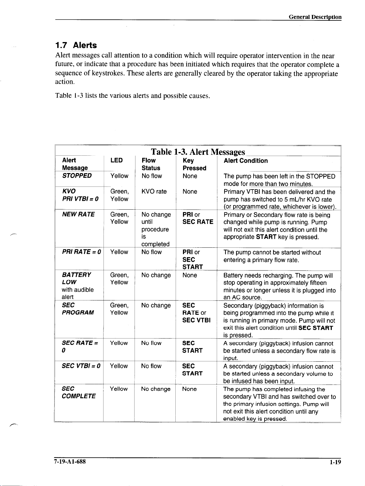
1.7 Alerts
Alert messages call attention to a condition which will require operator intervention in the near
future, or indicate that a procedure has been initiated which requires that the operator complete a
sequence of keystrokes. These alerts are generally cleared by the operator taking the appropriate
action.
Table l-3 lists the various alerts and possible causes.
r
Alert
Message
STOPPED
KVO
PRI VTBI = 0
NEW RATE
PRIRATE=O
LOW
with audible
alert
SEC
PROGRAM
SEC RATE =
0
SEC VTBI = 0
SEC
COMPLETE
LED
Yellow
Green,
Yellow
Green,
Yellow
Yellow
Green,
Yellow
Green,
Yellow
Yellow
Yellow
Yellow
Table 1-3. Alert Ic essages
Flow
Status
No flow
KVO rate None
No change
until
procedure
is
completed
No flow
No change SEC
No flow SEC
No flow
Key
Pressed
+
None
+
PRI or
SEC RATE
c
PRI or
SEC
START
None No change BATTERY
c
RATE or
SEC VTBI
c
START
SEC
START
None No change
Alert Condition
The pump has been left in the STOPPEI
mode for more than two minutes.
Primary VTBI has been delivered and th
pump has switched to 5 mL/hr KVO rate
(or programmed rate, whichever is lower
Primary or Secondary flow rate is being
changed while pump is running. Pump
will not exit this alert condition until the
appropriate START key is pressed.
The pump cannot be started without
entering a primary flow rate.
Battery needs recharging. The pump will
stop operating in approximately fifteen
minutes or longer unless it is plugged int
an AC source.
Secondary (piggyback) information is
being programmed into the pump while i
is running in primary mode. Pump will nc
exit this alert condition until SEC STAR1
is pressed.
A secondary (piggyback) infusion cannoi
be started unless a secondary flow rate i
input.
A secondary (piggyback) infusion cannoi
be started unless a secondary volume to
be infused has been input.
The pump has completed infusing the
secondary VTBI and has switched overt
the primary infusion settings. Pump will
not exit this alert condition until any
enabled key is pressed.
7-19-Al-688 1-19
Page 28
General Description
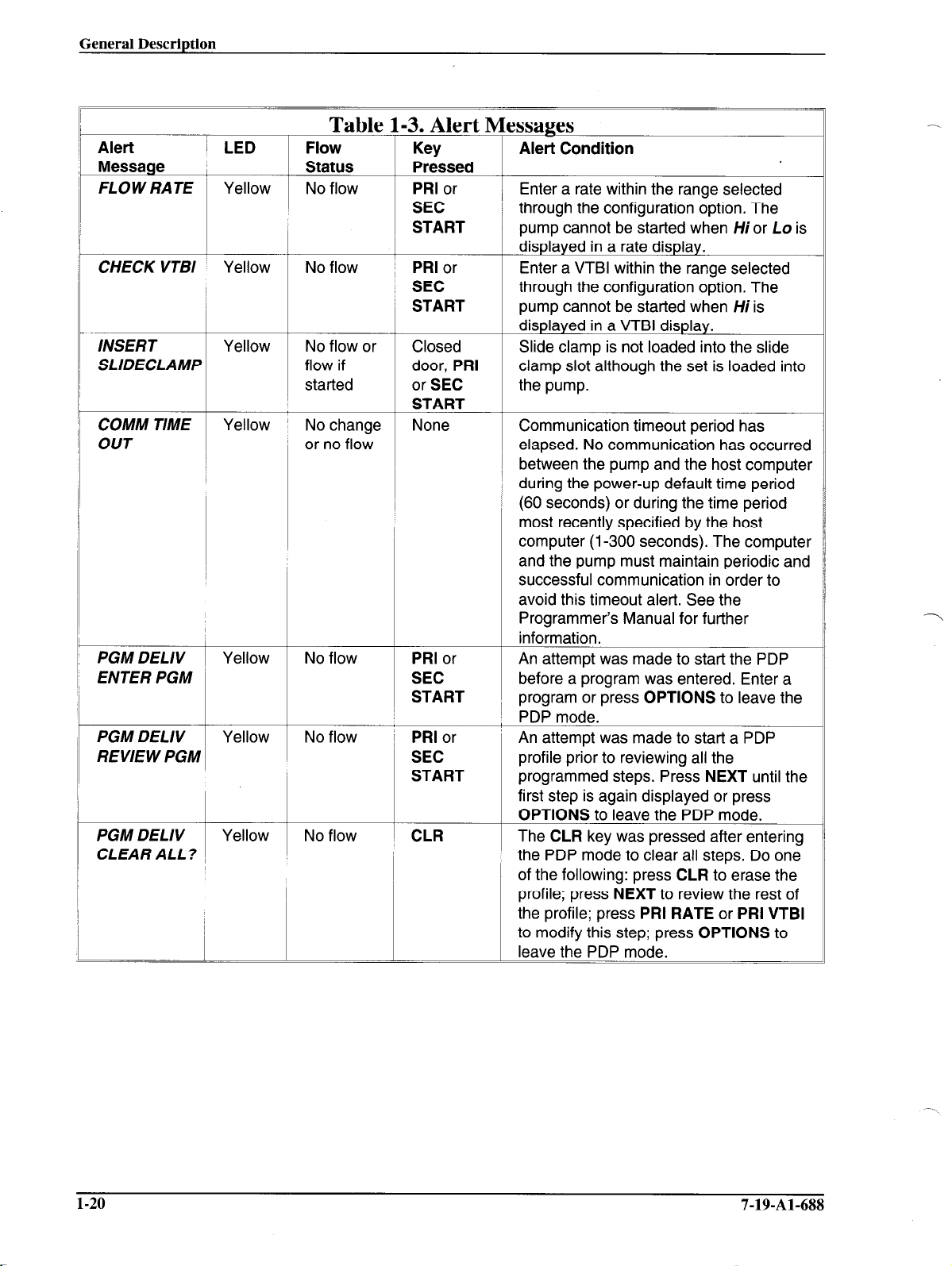
Table 1-3. Alert Messages
Alert 1 LED Flow
Message Status
FLOW RATE Yellow No flow
CHECK VTBI Yellow No flow PRI or Enter a VTBI within the range selected
INSERT Yellow No flow or Closed Slide clamp is not loaded into the slide
SLIDECLAMP flow if door, PRI clamp slot although the set is loaded into
started or SEC the pump.
COMM TIME Yellow No change None Communication timeout period has
OUT
PGM DELIV Yellow No flow PRI or An attempt was made to start the PDP
ENTER PGM SEC before a program was entered. Enter a
PGM DELIV
REVIEW PGM
PGM DELIV Yellow No flow CLR The CLR key was pressed after entering
CLEAR ALL? the PDP mode to clear all steps. Do one
Yellow No flow j PRI or An attempt was made to start a PDP
or no flow
Key
Pressed
PRI or
SEC
START pump cannot be started when Hior Lo is
I
SEC through the configuration option. The
START pump cannot be started when Hi is
START
START , program or press OPTIONS to leave the
SEC profile prior to reviewing all the
START programmed steps. Press NEXT until the
Alert Condition
Enter a rate within the range selected
I through the configuration option. The
displayed in a rate display.
displayed in a VTBI display.
elapsed. No communication has occurred
I
between the pump and the host computer
, during the power-up default time period
I (60 seconds) or during the time period
most recently specified by the host
computer (l-300 seconds). The computer
and the pump must maintain periodic and
successful communication in order to
avoid this timeout alert. See the
Programmer’s Manual for further
information.
j PDP mode.
first step is again displayed or press
OPTIONS to leave the PDP mode.
of the following: press CLR to erase the
profile; press NEXT to review the rest of
the profrle; press PRI RATE or PRI VTBI
to modify this step; press OPTIONS to
~ leave the PDP mode. ~ ~ ~
l-20 7-19-Al-688
Page 29
_-
,-
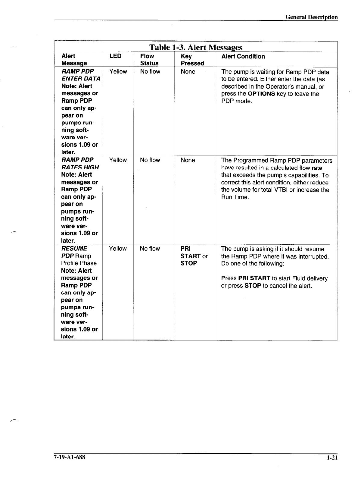
Table 1-3. Alert Messages
Alert LED Flow
Message Status Pressed
RAMP PDP
ENTER DATA to be entered. Either enter the data (as
Note: Alert described in the Operator’s manual, or
messages or press the OPTIONS key to leave the
Ramp PDP PDP mode.
can only appear on
pumps run-
ning software versions 1.09 or
later.
RAMP PDP
RATES HIGH
Note: Alert that exceeds the pump’s capabilities. To
messages or correct this alert condition, either reduce
Ramp PDP the volume for total VTBI or increase the
can only appear on
pumps running software versions 1.09 or
later.
RESUME Yellow No flow PRI The pump is asking if it should resume
PDP Ramp START or the Ramp PDP where it was interrupted.
Profile Phase STOP Do one of the following:
Note: Alert
messages or
Ramp PDP
can only appear on
pumps running soft-
ware ver-
sions 1.09 or
later.
Yellow No flow None
Yellow No flow None
Key
Alert Condition
The pump is waiting for Ramp PDP data
The Programmed Ramp PDP parameters
have resulted in a calculated flow rate
Run Time.
Press PRI START to start Fluid delivery
or press STOP to cancel the alert.
7-19-Al-688 1-21
Page 30

Page 31

Section 2
Hospital Service Procedures
This section contains a table describing preventive maintenance which should be performed on
the Flo-GardB 6201 Single Channel Volumetric Infusion Pump. The maintenance procedures
outlined in this section may be performed in the hospital. If an abnormal condition occurs which
is not correctable by performing the following procedures, remove the pump from service and
troubleshoot it in accordance with Section 5, or return it to Product Service for repair.
2.1 Replacement Of Main Power Fuse
1.
Plug the pump into an AC power outlet.
Check if the Plug Icon is illuminated.
2.
3.
If it is not, replace the fuse. Remove the power plug from the AC power outlet.
4.
Remove the power cord cover on the back of the pump and unscrew the fuse caps with a
small screwdriver.
Remove the fuses and check them for electrical continuity with an ohmmeter.
5.
If necessary, replace with a new fuse of the same value, type and voltage.
6.
7.
Replace and tighten the fuse caps with a screwdriver. Over tightening the fuse caps
may cause the fuse holders to break.
Replace the power cord cover.
8.
9.
Perform the Electrical Safety Test to verify proper grounding impedance. See Section
7.3.13.
7-19-Al-688
2-1
Page 32

Hospital Service Procedures
2.2 Cleaning
The pump should be cleaned as soon as possible after each use to minimize the accumulation
and hardening of spilled solutions. The case and front panel may be cleaned with a soft cloth or
cotton swabs dampened with a properly diluted cleaning agent listed in Table 2- 1.
Be sure to follow the manufacturer’s dilution instructions for concentrated cleaners where appli-
cable. Do not spray cleaning agents directly onto the inside of the pump door, the pump mechanism, and the front panel film. If these areas require cleaning, wipe carefully with a soft cloth,
sparingly dampened with a cleaning agent listed in Table 2- 1. If solution spillage onto the pumping mechanism or front panel occurs, it should be cleaned immediately. If necessary, contact
Product Service at 1-(800)-THE-PUMP.
-~
CLEANER
LpH, Septisol
Cidex 7
Super Edisonite
Bafix
Tor
Hi-Tor Plus
10% bleach and water
Soapy water
isopropyl alcohol (up to 95%)
Table 2-1. Cleaning Solutions
.-
MANUFACTURER
Vestal Labs, Inc.
Surgikos Inc.
Edison Chemical Co.
Hysan Corp.
Huntington Labs.
Huntington Labs.
Caution: Attempts to clean or disinfect internal parts, autoclaving or steriliza-
tion by ethylene oxide gas will damage the pump and void the warranty.
Caution: The following chemicals may damage the plastic front panel and tube
misloading sensors: Acetoldehyde, Acetone, Ammonia, Benzene, Hydroxytoluene, Methylene Chloride, n-Alkyl Dimethyl Ethyl Benzyl
Ammonium Chloride, and Ozone.
For a pump that has been in an Isolation Area, select those agents from Table 2-l that both clean
and disinfect. Only external parts of the pump should be disinfected. The following are procedures for cleaning accessible areas of the pump. Do not use hard instruments for cleaning.
1. Lift the door latch to the open position. Open the door and press the safety clamp latch
until it locks in the open position.
2-2
7-19-Al-688
Page 33

Hospital Service Procedures
2. Using a cotton swab dampened with one of the agents listed in Table 2-1, clean all tubing guides and tubing channels from the top of the pump to the exit point below the
safety clamp. Clean all surfaces in the pump head which may contact the tubing.
3. Clean all surfaces of the air sensor located just above the safety clamp. This area must be
completely dry and free of foreign matter prior to reuse.
2.3 Battery Charging
The battery is recharged whenever the pump is plugged in regardless of whether the pump is on
or off. However, for optimal charging, turn the pump off. The Plug Icon is illuminated whenever
the battery is charging. The battery must be stored in a charged condition and should be recharged at least once a month. To charge the battery, simply plug the pump into a 115 VAC outlet.
7-19-Al-688 2-3
Page 34

Hospital Service Procedures
2-4
2.4 Preventive Maintenance
Table 2-2 lists preventive maintenance for the pump, which should be performed at the intervals
shown.
Table 2-2. Preventive Maintenance Procedures
CHECK ACTION
Schedule: As required, but recommended after every use.
Pump mechanism
Case
Clean with an agent listed in Table 2-l.
Clean with an agent listed in Table 2-l.
I
Rear Panel
Connector
(comm port)
Loose or missing
hardware
Main Battery
Schedule: Every 12 months or as required
Back plate and
safety clamp
Pole clamp
Power cord
Clean with an agent listed in Table 2-l.
Replace the connector if its shell is damaged.
Check that plastic cover is in place.
1
Replace in accordance with Section 6.
Recharge by plugging into a 115 VAC outlet for at least 8 hours.
Check that the Plug Icon is illuminated during this time.
L
If the safety clamp or back plate does not operate smoothly, clean or
replace in accordance with Section 6.3.14 or 6.3.17.
If operation is not smooth, apply one drop of high grade general purpose
machine oil to the screw threads.
Replace power cord if the pins are bent or the insulation is damaged.
Preventive Perform the appropriate tests as detailed in Section 7.3 Operational
maintenance tests 1 Checkout.
7-19-Al-688
Page 35

,-
Section 3
Problem Checklist
Table 3-l is a list of problems, checks and corrections to aid in the diagnosis of possible pump
malfunctions. Corrections contained in the table can be performed without opening the pump
housing. Review this list whenever a condition exists that does not appear to be normal. Perform
the specified checks and corrections. If the problem cannot be corrected, remove the pump from
service. Troubleshoot it in accordance with Section 5 and repair it in accordance with Section 6.
Table 3-1. Problem Checklist
PROBLEM
The plug icon is not lit when
the pump is plugged in,
or
the battery icon is lit when
the pump is plugged in.
The pump fails to run on the
internal battery (No LCD dis-
plays appear).
The pump stops with BAT-
TERY LOW alarm.
CHECKS
Check the tightness of the
power olua into the AC outlet.
Check the rear power fuses
under the power cord cap.
Check the AC outlet for proper
voltage.
Check the line cord for
continuity.
After recharging the battery for
24 hours with the pump turned
off, check the battery charging
voltage, MB, per Section 53.1.
No check required.
CORRECTIVE ACTION
Press the power plug firmly into
the grounded AC outlet.
Replace the fuse(s) if it has
failed and recharge the battery.
If the voltage is below 105 VAC,
connect the pump to the correct
supply voltage.
Connect the power terminals of
the power plug to an ohmmeter.
The ohmmeter should indicate
continuity.
If the battery charge voltage is
normal and the problem still
persists, replace the battery.
See Section 6.3.18.
Recharge the battery.
7-19-Al-688
3-1
Page 36

Problem Checklist
1
PROBLEM
The pump door will not open
or close smoothly.
The audible alarm volume is not loud enough.
The interval between audible alarm tones is too long.
The backlight is off when the pump is running on internal battery
power.
A RATE, VTBI, or START
key is not accepted by the
pump
Hi or Lo is displayed during
Volume-Time programming.
A FLOW RATE or CHECK
VTBl alarm occurs when a
START kev is pressed.
Table 3-1. Problem Checklist
CHECKS
Check the positioning and
seating of the administration set
tubing and the slide clamp.
Check the administration set for
type and code.
Check for solution spills (liquids
or residues).
Check that the door latch roller
pin turns smoothly.
Check for possible damage to
the door latch, latch pin roller, or
door hinge.
r
Check if the front panel is locked
(Lot appears in Main Display).
L
Calculate the rate and verify that
it is within the allowable range
set by the configuration option.
Check that the rate or VTBI are
within the limits set by the
configuration option.
CORRECTIVE ACTION
Position the tubing and the slide
clamp properly and make
certain they are seated in the
guides.
Replace with a Baxter’s “s”
suffix administration set if
required.
Clean all accessible areas with
cotton swabs dampened with
one of the cleaners listed in
Section 2. Remove fibers or
foreign particles. Do not use
hard instruments for cleaning.
Clean the roller with an
approved cleaner.
See Section 6.3.5 for
instructions on replacing the
door latch and Section 6.3.7 for
replacing the latch pin.
Replace door as described in
Section 6.3.6.
Turn the VOLUME knob on the
rear of the pump clockwise until
the desired volume is obtained.
Change the interval for alert
and/or alarm tones to the
desired value through the
configuration option.
Press the BACKLIGHT key as
long as required to view the
pump settings.
Press the PANEL LOCK switch
to remove the panel lock.
Enter a rate within the range set
by the configuration option or
change the maximum rate
setting in the configuration
option if appropriate.
Change the maximum rate
and/or maximum VTBI setting
through the configuration option.
3-2 7-19-Al-688
Page 37

PROBLEM
An AIR alarm occurs with no
air in the tubing or with the
pump door closed and the
START key pressed.
An OCCLUSION alarm or
an UPSTREAM
OCCLUSION alarm occurs
with the pump door closed
and the START key pressed.
An INSERT SLIDECLAMP
alert or alarm occurs when
the pump door is closed.
Note: The alarm option is
available only on pumps
running software versions
1.09 or later.
Table 3-1. Problem Checklist
CHECKS
Check the positioning and
seating of the tubing.
Check the tubing for surface
scratches and for tube
roundness.
Check the administration set for
type and code.
Check for solution spills (liquids
or residues).
Check the positioning and
seating of the tubing.
Check that there are no
obstructions upstream or
downstream of the pump.
Check the administration set for
type and code.
Check that ambient and solution
temperatures are above 60” F.
Check for solution spills (liquids
or residues) on the inside of the
door and/or on the baseplate.
Check that the slide clamp is in
the slide clamp slot.
Check for solution spills (liquids
or residues) on the slide clamp
or safety/slide clamp assembly.
Check if the administration set is
equipped with the slide clamp
designed for use with this pump.
See the instructions
accompanying the
administration set.
Problem Checklist
CORRECTIVE ACTION
Position the tubing fully into the
air sensor.
Replace or reposition the tubing
if surface scratches are
significant or if the tubing has
become flattened or oval in
shape.
Replace with Baxter’s “s” suffix
administration set.
Clean the sensor with cotton
swabs dampened with one of
the agents listed in Table 2-l.
Remove fibers or foreign
particles. Do not use hard
instruments for cleaning.
Position the tubing properly into
the sensor and safety clamp.
Correct any pinched or kinked
tubing in the pump.
Remove obstructions and/or
open the roller clamp.
Replace with Baxter’s “s” suffix
administration set if required.
Raise ambient and/or solution
temperatures.
Clean all accessible areas with
cotton swabs dampened with
one of the cleaning agents listed
in Table 2-1. Remove fibers or
foreign particles. Do not use
hard instruments for cleaning.
Push the slide clamp all the way
into the slide clamp slot.
Clean the safety/slide clamp
assembly.
If not, use an administration set
which has the proper slide
clamp for use with the pump.
Inset-t the slide clamp into the
slide clamp slot before closing
the pump door.
7-19-Al-688
3-3
Page 38

Problem Checklist
PROBLEM
The safety clamp will not
latch open.
A CHECK SET/LOADING
alarm occurs when the
pump door is closed.
Table 3-1. Problem Checklist
CHECKS
Check the positioning and Push the slide clamp all the way
seating of the slide clamp in the into the slide clamp slot.
slide clamp slot.
Check if the administration set is If not, use an administration set
equipped with the slide clamp which has the compatible slide
designed for use with this pump. clamp. Insert the slide clamp
See the instructions into the slide clamp slot before
accompanying the closing the pump door.
administration set.
Make sure the safety clamp arm
cover is in the full open position.
Check for solution spills (liquids
or residues).
Open the door and check the
position of the tubing in the
guide channel.
CORRECTIVE ACTION
Exercise the safety clamp by
opening and closing it several
times.
Clean with cotton swabs
dampened with one of the
cleaning agents listed in Table
2-l. Remove fibers or foreign
particles. Do not use hard
instruments for cleaning.
Load the set properly in the
guide channel.
3-4 7-19-Al-688
Page 39

Section
4
Theory of Operation
This section covers the operating principles of the pump. The theory of operation does not cover
the specific circuitry in great detail, but provides general information needed to perform fault
isolation. Active-low signals on all schematic diagrams in Section 10 are denoted by an exclamation point (!) preceding the signal name. Figure lo- 1 is a block diagram of the major
components in the pump. The numbers at the upper left of each block refer to the number of the
figure in Section 10 in which the major components of that block are shown in greater detail.
4.1 CPU System
4.1.1 CPUS
See Figures 10-6 and 10-7. The pump uses two identical CPUs, UlOl and UOOl. Normally,
UlOl and UOOl act as master and slave, respectively.
The master CPU controls all pump functions except motor control, which is handled by the
slave CPU. The master CPU sends rate information and motor start/stop messages to the slave
CPU and also monitors the motor control by the slave CPU.
The master CPU gathers data from and/or controls the interlock switch, the power control cir-
cuit, the communication controller, two I/O controllers, the occlusion detection multiplexer, the
RAM, the real time clock, the air sensor, the universal pulse processor and the alarm control circuit.
The master CPU also handles RS-232 serial communication with an external computer through
the communication controller.
The slave CPU controls the pump motor via the motor control circuit in three ways:
l
Generates pulses to rotate the motor.
l
Monitors motor skip step by checking the signal from the motor rotation detector.
-
l
Controls the motor current while minimizing current draw from the battery. It also controls
the alarm control circuit.
7-19-Al-688
4-l
Page 40

Theory of Operation
The slave CPU outputs an interrupt signal to the master CPU through the universal pulse proces-
sor after every one-eighth of the liveband period to provide air bubble detection timing to the
master CPU.
Both CPUs handle the watchdog function, which is the periodic communication between the
CPUs through two serial communication lines at 15,625 baud.
The CPUs, in conjunction with the two 64K x 8 EPROMs, utilize 16 address lines and eight data
lines.
The master CPU addresses an EPROM, RAM, Real Time Clock, universal pulse processor, two
I/O controllers and the communication controller. The slave CPU addresses an EPROM, RAM
and programmable timer module. The software in the EPROMs for master and slave CPUs is
different.
4.1.2 Programmable Timer Module (PTM)
See Figure 10-10. The programmable timer module (PTM) divides the 8 MHz system clock into
500 kHz for the oscillation of the air sensor and also generates a signal for pulse width modulation control of the motor driver.
The slave CPU calculates and outputs motor drive signals based on the rate information from
the master CPU. It also sets a motor current level in the PTM from a reference table.
4.1.3 Watchdog Function
The watchdog function is performed in two ways:
Both CPUs monitor each other’s status. The purpose of this watchdog is to detect a malfunction
of either microprocessor and stop the pump with an alarm. See Figures 10-7 and 10-9. Both
CPUs communicate through the two serial communication lines, TX and Rx. Each CPU has a
communication counter, which is initialized to a predetermined value by a signal from the other
CPU. The counter is then decremented by one count every 32.768 mS. The counters are nor-
mally initialized again by the signal from the other CPU before they decrement to zero. If a
counter reaches zero, it indicates that the watchdog signal from the other CPU was never received. This indicates a problem with the other CPU. The remaining functional CPU then stops
the pump with visual and audible alarms.
If communication between the CPUs cannot occur, both CPUs stop the pump with visual and
audible alarms.
Should both CPUs fail at the same time, this watchdog function does not work. The alarm control circuit is provided as a backup watchdog function. See Figure 10-9. Signals from each CPU
are the inputs to the alarm control circuit.
When both CPUs are functioning normally, the signals change their state periodically. The soft-
ware to control the signals is divided into several parts and located in different portions of the
4-2 7-19-Al-688
Page 41

main program. The state changes of the signals are considered normal only when all the individual parts of the program are executed according to an expected sequence.
If either or both signals fail, the alarm control circuit is triggered and stops the pump with visual
and audible alarms.
The accompanying audible tone whenever either watchdog function is activated is continuous
rather than intermittent.
4.1.4 I/O Controllers
See Figures lo-16 and 10-17. The I/O controller U601 performs the following functions: activat-
ing backlight, addressing the keyboard and scanning the ON-OFF/CHARGE key, PANEL
LOCK switch and LCD drivers, and writing display data from the master CPU into the display
drivers.
The other I/O controller, U602, performs the following functions: controlling the air and occlu-
sion sensors, and activating all LEDs and icons except ALARM and OPTIONS LEDs and key
beep. It also transfers the slide clamp sensor signals to the master CPU.
4.1.5 Multiplexer
See Figure lo- 14. The multiplexer, U85 1, selects one of the two occlusion sensor outputs in ac-
cordance with the address signals from an I/O controller, and sends it to the master CPU.
4.1.6 Universal Pulse Processor
See Figure 10-8. The universal pulse processor (UPP) is controlled by the master CPU and converts the following analog signals into digital signals: air sensor outputs, tube misloading sensor
outputs, battery voltages, motor currents and the voltage of the CPUs. The digital signals are periodically read by the master CPU.
The UPP generates 2 kHz and 4 kHz signals for the audible alarm and key beep and a 17 kHz
signal for the door open sensor, and the signal for backlight dimming.
The UPP also interrupts the master CPU each time a pulse is received from the motor rotation
detector, when an interrupt signal from slave CPU is received or when the pump communicates
with an external PC.
The UPP is used to select the baud rate for external communications. The baud rate is set at
power-up according to the configuration setting.
7-19-Al-688
4-3
Page 42

Theory of Operation
4.1.7 Communication Controller
See Figures lo- 11 and lo- 18. The communication controller allows the pump to communicate
with an external computer through an RS-232C interface. The baud rate is selectable and conlrolled by the universal pulse processor.
4.1.8 Air Sensor Circuit
See Figures lo-14 and 10-28. The circuit consists of an ultrasonic transmitter and receiver
mounted on opposite sides of the tubing path. The transmitter consists of a 500 kHz oscillator
and a selector that transfers the oscillator output to two of three transducers. The transducers are
selected by the air bubble alarm size setting in the configuration option. The receiver contains a
selector that transfers the transducer outputs to the UPP through an amplifier.
The transducers operate on the principle that air in the tubing transmits ultrasonic energy much
less effectively than fluid. This energy is amplified, rectified, applied to the UPP and then converted into a digital signal. The master CPU monitors the signal and activates an
AIR
alarm if it
detects the absence of a precise level of energy.
4.1.9 Occlusion Sensors
4.1.9.1 Downstream Occlusion Sensor
See Figures lo-14 and 10-28. The downstream occlusion sensor consists of a moving ferrite
core inside a mechanically fixed oscillator coil. The moving ferrite core is spring loaded against
the IV set tubing. When pressure downstream of the pump increases, the core moves from its
original position, which in turn changes the frequency of the oscillator.
The downstream occlusion sensor output is selected by the multiplexer, applied to the master
CPU and compared to the occlusion level selected in the configuration option. If the occlusion is
sufficient to cause a specific frequency change, the CPU activates an alarm. There is a maximum expansion of the tubing beyond which the pump will no longer permit operation.
The downstream occlusion sensor operates in a frequency range of 1.3 MHz to 1.45 MHz.
4.1.9.2 Upstream Occlusion Sensor
See Figures lo-14 and 10-28. The upstream occlusion sensor is similar to the downstream occlusion sensor (except for the spring) but is not tuned to the same frequency and is controlled by
different software.
The upstream occlusion sensor output is selected by the multiplexer and applied to the master
CPU. Because the tubing collapses somewhat during normal operation, the software looks for a
collapse that is faster and/or farther than expected. If the rate of collapse is too fast or too far,
the pump alarms. There is a maximum tubing collapse beyond which the pump will no longer
permit operation.
The upstream occlusion sensor operates in a frequency range of 1.2 MHz to 1.35 MHz.
4-4
7-19-Al-688
Page 43

4.1 .I 0 Tube Misloading Detector
See Figures 10-8 and 10-28. The pump head has a Force Sensing Resistor* device (FSR**) at-
tached to each side of the tube loading channel. If the tube is misloaded over the FSR, its resistance decreases. The two FSR output voltages are converted into digital signals by the UPP and
monitored by the master CPU. The CPU activates an alarm when the resistance decreases below
a specified level.
4.1 .I 1 Slide Clamp Detector
See Figures lo-17 and 10-28. The slide clamp sensor consists of two opto-interrupters contained
in the safety/slide clamp assembly. If the slide clamp option is selected via the configuration option settings, the administration set slide clamp should be loaded into the slide clamp slot in order to avoid an alert or alarm condition. If the slide clamp is not loaded into the slide clamp slot,
or is loaded improperly, the opto-interrupters do not receive reflection signals. The interrupter
output voltages are read and monitored by the master CPU via the I/O controller. The CPU activates an alert or an alarm (software versions 1.09 or later) when the slide clamp is not loaded
and the option has been selected.
4.1 .I2 Battery Low Alert/Alarm Detector
See Figure 10-8. The battery voltage is converted into a digital signal by the UPP and monitored
by the master CPU. The CPU activates the alert or alarm if the battery charge state falls too low.
The
BATTERY
approximately 15 minutes of operation. The
LOW alert is triggered if the battery voltage drops below 11.4 V, which permits
BATTERY LOW
alarm is triggered when battery
voltage drops below 10.4 VDC, which stops the pump with an alarm to prevent the battery from
being damaged.
4.1 .I 3 Interlock Switch
See Figure 10-28. The interlock switch is a reed type, activated by a magnet attached to pump
door latch. The switch opens the circuit when the pump door is opened. The master CPU moni-
tors the interlock switch, activates the
DOOR OPEN
alarm and stops the pump when the door is
opened.
4.1 .I 4 Panel Lock Circuit
See Figure 10-16. The panel lock circuit is initiated by the PANEL LOCK pushbutton switch located on the rear of the pump. The switch is connected to an I/O controller. The purpose of this
circuit is to prevent patient tampering. After the PANEL LOCK switch has been pressed, the
message
Lot
is displayed in the unused rate window and no keys except TOT VOLBTATUS
* Interlink Electronics
**Interlink Electronics
7-19-Al-688
4-5
Page 44

and BACKLIGHT are accepted. The panel lock out is released by pressing the PANEL LOCK
switch again. The switch is enabled only when the pump is infusing without an alert.
4.1 .15 Keypad
See Figures 10-29. The keypad is a multiplexed 8 x 4 array that is scanned by an I/O controller.
One of eight select lines determine which four keys are read. All normal keypad depressions are
decoded by this matrix except the ON-OFF/CHARGE key, which has special input to the power
control circuit.
4.1 .16 Displays
See Figures lo-21 and 10-22. The LCD displays are multiplexed by display drivers, which apply
a DC biased free-running frequency AC voltage to the segments of the displays when in the ON
state, and no DC biased AC voltage when in the OFF state. The display drivers are addressed by
the master CPU through an I/O controller. The data is sent on the data bus and is coded to update the display periodically. Once addressed, the display driver retains the data until addressed
again. The entire display is updated every 128 msec.
The display backlight is toggled on or off by the BACKLIGHT key. If the pump is running on
AC power, the backlight stays on continuously. If the pump is running on the battery, the backlight shuts off after 60 seconds to conserve battery life.
7
4.1 .I 7 Motor Driver
See Figure lo- 15. The motor driver receives four separate motor drive signals from the slave
CPU, which are effectively ANDed with a pulse width modulation (PWM) signal from the programmable timer module. The PWM signal controls the current level required for proper motor
operation. The motor current level is converted into digital signal by the UPP and monitored by
the master CPU, which activates an alarm and stops the pump if motor overcurrent is detected.
The user-defined rate is saved in two different memory locations which are compared against
each other and the feedback from the motor rotation detector to guard against any non-programmed rate changes.
Snubbing diodes have been added to increase motor efficiency. The motor is shut down when an
alarm or a failure occurs. The motor speed range permits infusions from 1 mL/hr to 1999 mLkr.
4.1 .18 Motor Rotation Detectors
See Figures 10-8 and 10-28. The motor rotation detector assures that pump drive rotation occurs
or the motor shuts down. The motor rotation signal is read by the master CPU via the UPP and
slave CPU. The sector signal is read by the slave CPU and utilized for controlling motor current.
4-6
7-19-Al-688
Page 45

Theory of Operation
4.2 DC Power Supply and Power Control Circuit
See Figure 10-30. The DC power supply circuit is a switching type, which provides a regulated
13.65 V output at 0.85A maximum. The circuit will charge the battery as long as the pump is
connected to a specified AC outlet. The design continues to supply useful output down to a
105.0 VAC input. Two 500 mA slow blow replacement fuses are required for AC. A 2.OA fuse
is required in the battery circuit. Whenever the supply is activated by AC voltage, the Plug Icon
on the front panel is lit. The DC power supply has over-voltage and over-current protection.
The power supply circuit on the CPU board (Figure 10-13) generates several DC sources from
the 13.65 V output of the DC power supply board, (when the pump is plugged into a specified
AC source) or from the internal battery. The +5 VDC lines are shown below. See Section 6.4.1
for voltage specification limits.
Vcpu: This line is the output of a DC to DC convertor, HIC301, and is switched by the
master CPU. Vcpu is the main DC source voltage of the pump. Motor current
does not flow while VcpU is off.
Vref: This is the reference voltage regulated by a filter and a reference diode (U502:
LM336M-5.0) for the A/D convertor in the UPP. This voltage is generated from
Voth, which is switched by the master CPU.
Vkey: This is generated either from the output of the DC power supply board, or from
the internal battery voltage and is used for monitoring the ON-OFF/CHARGE
key. This is the unswitched power source.
Other DC voltages used in the pump are as follows:
Vmtr: This is the DC source for the motor. It comes either from the DC power supply
output or the internal battery voltage. This is the unswitched power source.
Voth: This is used for backlights, icons and optional nurse call feature. The voltage
comes from the DC power supply output and is switched by the master CPU.
Vmem: This is the output of the lithium backup battery for the backup memory in the
RAM (U507) and for maintaining the time in real time clock (U506). This is the
unswitched power source.
All the voltages except unswitched power sources are turned on when the ON-OFF/CHARGE
key is pressed while the pump is off. However, turning these voltages off can only be accomplished by the master CPU through the power control circuit.
The master CPU saves necessary data in the back up memory in the RAM (U507) and turns off
the Vcpu, Vref and Voth voltages when the pump is turned off.
7-19-Al-688
4-7
Page 46

‘I heory of Operation
The power control circuit is contained in a hybrid chip, HIC302, which also includes a circuit to
activate the backup audible alarm when the pump is shut down by a failure. The RAM (UO06)
f~>r the slave CPU is not backed up.
-.
4-8
7-19-Al-688
Page 47

Section
Troubleshooting
5.1 Introduction
This section describes how to find the cause of pump malfunctions. The section consists of the
following:
l
A description of the pump’s Failure Identification Codes.
l
A description of the pump’s automatic test modes.
l
A table which lists each failure code, its cause, and ways of correcting it.
5
l
A table which describes how to correct problems not represented by failure codes.
Once the cause of a failure has been determined, perform the corrective action given in the table.
All disassembly/reassembly and calibration procedures for the pump are in Section 6. To verify
the effectiveness of repairs after they are completed, perform the Operational Checkout procedures given in Section 7.
5.2 Failure Identification Codes
Specific errors which may occur during pump operation are represented by Failure Identification
Codes. When the alarm message
ber. This code is the Failure Identification Code. The last 10 Failure Identification Codes (including alarm codes except
stored in the pump’s memory, along with the date and time at which the alarm occurred. The
Failure Identification Codes can be used to determine the nature of a pump failure and to troubleshoot its cause.
To view the stored Failure Identification Codes, press the STOP key. Press and hold the SILENCE and TOT VOLKTATUS keys. The most recent Failure Identification Code will be displayed in the lower right comer of the Main Display. The time at which the failure occurred will
be displayed in the upper right comer of the Main Display. The date when the failure occurred
will be displayed in the Message Display for as long as the keys are held, plus one second. To
FAILURE
DOOR OPEN
occurs, it is accompanied by a two-digit code num-
and
AIR
alarms occurring in the stopped mode) are
7-19-Al-688 5-l
Page 48

Troubleshooting
exit from the Failure Identification Code viewing mode, release the SILENCE and TOT
VOL/STATUS keys. One second later, the display of the RATE(s) and VTBI(s) data resumes.
To scroll back through the previous nine codes that occurred, press the CLEAR TOT VOL key
before the one second period elapses. Each failure code, along with the time and date, will be
displayed for one second with a one second off interval after each code. After the last failure
code has been displayed for 1 second, the display returns to normal. To exit, press the STOP key.
See Table 5-l for descriptions of all Failure Identification Codes and instructions on how to correct each failure. Disassembly/reassembly and calibration procedures are located in Section 6.
During operation, a pump failure is indicated by the message
FAlLURE
and the failure code num-
ber (in the format, F-nn) in the Message and Main Displays.
5.3 Automatic Test Modes
Warning: The automatic test modes are for servicing the pump only, and must
not he used while the pump is connected to a patient.
The pump has ten automatic test modes to aid in troubleshooting and manufacturing. The ten
modes are described briefly in the following paragraphs. The procedure to access any of the
automatic test modes is as follows:
1. Turn the pump off.
-
2. Press and hold the CLEAR TOT VOL key and while pressing the numeric key corresponding to the automatic test mode you wish to enter (1 through 0).
3. While performing step 2, press the ON-OFF/CHARGE key.
4. To exit any automatic test mode, press the ON-OFF/CHARGE key.
5.3.1 Automatic Test Mode 1: Calibration Mode 1
The purpose of this calibration mode is to check the calibration of the upstream and downstream
occlusion sensors, and to check the pump’s internal DC voltages from the power supply.
1. Place the pump on its back. Enter Automatic Test Mode 1.
2. Place the thickness gauge (part no. UKOG1013.B) onto the downstream occlusion sensor.
3. Close the pump head door.
-7
4. Plug the pump into a 115 f 5.0 VAC, 60 Hz power source.
5-2 7-19-Al-688
Page 49

5. Check that the value displayed in the PRI VTBI window of the Main Display is between
2967 and 3039. No calibration is required if the values are within the specification.
If the value is out of specification, perform Section 6.4.3, steps 2 and 3.
6.
7. Place the thickness gauge used in step 2 onto the upstream occlusion sensor.
8. Close the pump door.
9. Check that the value displayed in the PRI RATE window of the Main Display is between
3242 and 3314. Remove the thickness gauge, close the door, and check that the value is
3080 or less.
10. If the value is out of specification, perform Section 6.4.4, steps 2 and 3.
11. Check that the voltage readings in the SEC RATE and SEC VTBI windows are within
specification:
Note: The pump must be plugged in to obtain voltage readings within the
specifications below.
/--
Descriptor Window Displayed
Vmain = MB
Vme,,, = BB SEC VTBI
SEC RATE
Specification
688-714
574-737
(a)
(b)
Note: (a) Actual voltage = Displayed data x 0.01953
(b) Actual voltage = Displayed data x 0.00488.
12. If the BB display is out of specification, replace the lithium backup battery per Section
6.3.28.
13. MB is a value relating to the voltage of the charging circuit. If the MB display is out of
specification, turn the pump off and charge it for 8 hours. Repeat steps 1 and 11. If the
MB display is still out of specification, perform the following procedure.
14. Remove the battery cover by removing 4 screws (Figure 8-4 item 27) on the battery
cover located on the back of the pump. Disconnect the main battery at the battery terminals and perform steps 1 and 11.
15. If the MB display is out of specification, the DC power supply must be calibrated per
6.4.1.
7-19-Al-688
5-3
Page 50

Troubleshooting
16. If the MB display is within specification as described in Step 11, the main battery should
be replaced per Section 6.3.18.
5.3.2 Automatic Test Mode 2: Calibration Mode 2
The purpose of this Automatic Test Mode is to check the calibration of the air sensor and to
check the tube misloading sensor outputs.
Open the door and check for a white tubing guide shim or the letter “A” on the door opposite the
air sensor. If the shim or “A” is present, use the air sensor calibration values of 330 - 565 (if the
shim or “A” is NOT present, use the calibration values of 400 - 650)
1. Plug the pump into a 115 f5.0 VAC, 60 Hz power source. Enter Automatic Test Mode 2.
2. Load a Baxter’s “s” suffix standard administration set and prime it with fluid. Close the
pump door. Ambient and solution temperatures must be between 72” and 82” F (22”
and 28” C).
3. Open and close the pump door two more times and wait 2 minutes.
4. Check the NORM value (at PRI RATE window) and the MIN value (at PRI VTBI window). Both values should display between 330 and 565 or 400 and 650 (Check above for
the proper values).
5. Remove the primed tubing and load an unprimed calibration tubing segment and close
the door. Open and close the door two more times and wait 2 minutes. View the NORM
value displayed in the PRI RATE location at the upper left of the device’s main display.
Next, view the MIN value displayed in the PRI VTBI location at the lower left of the
main display. Both values must be less than 11. If they are out of specification, perform
the procedure in Section 6.4.2.
6. Follow steps 7 through 11 to check that the tube misloading sensor outputs in SEC
RATE and SEC VTBI windows are within specification.
7. Load a Baxter’s “s” suffix standard administration set and prime it with fluid.
8. With the pump door open, check the FSRR value (at SEC RATE window) and the FSRL
value (at SEC VTBI window). Both values should display between 500 and 820.
9. Repeat above step with the pump door closed. Both values should display between 500
and 820.
5-4
7-19-Al-688
Page 51

,-
10. Open the door and intentionally load the tubing over the tube misloading sensor 2L (Figure 8-6, item 10). Close the door. Do not load hard components on the administration
set between the door and the base plate. The FSRL value (at SEC VTBI window)
should display 450 or less.
11. Repeat above step on the tube misloading sensor 2R (Figure 8-6, item 11). The FSRR
value (at SEC RATE window) should display 450 or less.
Note: The sensors are normal if the values in steps 8 through 11 are within
specification. If any of these values are out of specification, replace
the tube misloading sensor per Section 6.3.12.
Press the TIME key and check that the voltage Vcpu reading in the SEC RATE window
12.
of the display is within 472 - 579. Actual voltage = displayed data x 0.00976.
5.3.3 Automatic Test Mode 3: Manufacturing Test Mode
Warning: This is an automatic test mode for testing the pump during manufac-
turing only. This mode must not be used on patients because the
downstream occlusion, upstream occlusion and air sensors are disabled.
The initial display in this automatic mode is for a PRI RATE of 1999 mL/hr, PRI VTBI of 3998
mL, SEC RATE of 500 m/hr, and SEC VTBI of 100 mL. Pressing the TIME key changes the
primary settings as follows:
PRI RATE PRI VTBI SEC RATE SEC VTBI
999 1998
499 998
250 ..--.-
125 250 500
10 20 500 100
500 _ 500 100
In each combination, the primary and secondary rates and VTBI can be manually altered.
500
500
100
100
100
The pump will stop automatically one hour after the PRI START key was pressed. While the
pump is running, the air sensor and the upstream and downstream occlusion sensors are disabled.
5.3.4 Automatic Test Mode 4: Aging Mode
Warning: This is an Automatic Test Mode for testing the pump during manu-
facturing only. This mode must not be used on patients because the
rates and VTBI settings cannot be altered.
While the pump is stopped, pressing any numbered key (0 - 6) programs a preset rateNTB1 com-
bination as follows:
7-19-Al-688
5-S
Page 52

Troubleshooting
Key Number PRI RATE PRI VTBI SEC RATE SEC VTBI
0 500 3000 999 6000
1 499 0 999 1
2 3 0 0 0
-3 250 0 0 0
4 499 100 0 0
5 1401 100 0 0
6 1999 100 0 0
_~
The RATENTBI keys and number keys 7, 8, and 9 are not accepted. Other specifications are
the same as during normal operation.
5.3.5 Automatic Test Mode 5: Display Check Mode
All the LCD segments, LEDs and icons turn on sequentially for a visual check each time the
STOP key is pressed. At any point in the sequence the SEC START key may be pressed to return to the beginning of the sequence.
5.3.6 Automatic Test Mode 6: Time Information Display Mode
In this test mode, the cumulative time values are displayed sequentially each time the SEC
RATE key is pressed. The test mode first displays the cumulative Power On time, then the time
on battery and finally, the time that the pump was actually pumping. It should be noted that the
first six digits from the left are the time in hours and the two digits on the right are the time in
minutes. Therefore, the display 0007 02:27 represents 102 hours and 21 minutes.
5.3.7 Automatic Test Mode 7: Pumping Sensor Monitoring Mode
Warning: This is an automatic test mode for testing the device during manufac-
turing only. This mode must not be used on patients.
In this test mode, the motor current.and occlusion sensors may be monitored during pumping.
During pumping, the motor current is displayed in the PRI VTBI location, the upstream occlu-
sion detector reading in the SEC RATE location, and the downstream occlusion sensor reading
in the SEC VTBI location. When the pump is stopped, all of the displayed values return to nor-
mal.
5.3.8 Automatic Test Mode 8: Air Sensor Test Mode
Upon entering this mode, the PRI RATE is set to 30, PRI VTBI = 100, SEC RATE = 600, and
SEC VTBI = 100. Pressing the TIME key selects the pump’s air sensor sensitivity (MIN or
NORM) without using the configuration option. The air sensor selection is displayed in the mes-
5-6 7-19-Al-688
Page 53

Troubleshooting
sage display when the pump is started. All other keys function normally except for the TIME
key. Rate and VTBI information for both primary and secondary mode may be changed.
5.3.9 Automatic Test Mode 9: Elapsed Time Test Mode
The elapsed pumping time is displayed in the first line of the message display in this test mode.
Momentarily pressing the TIME key selects two pre-programmed primary mode test conditions.
The first is a PRI RATE of 125 mL/hr with a VTBI of 100 mL. The second is a PRI RATE of
499 mL/hr with a VTBI of 100 mL. The elapsed time counts only when the pump is running.
Stopping the pump and then restarting it will reset the timer to zero. All keys except the TIME
key work normally. When the VTBI has been delivered, the pump will enter KVO mode.
53.10 Automatic Test Mode 0: Downstream Occlusion Test Mode
In this mode, pressing the TIME key will allow you to select the pump’s downstream occlusion
level sensitivity without entering the configuration mode. The selected occlusion sensor level (1,
2, or 3) is momentarily shown in the second line of the message display until the test mode is exited. After exiting test mode, the downstream occlusion sensor level will revert back to the original configuration setting. Rate and VTBI information may be programmed manually.
5.4 Failure Identification Code Troubleshooting Table
Use Table 5- 1 to determine the corrective action necessary to resolve failure codes. The causes
of each failure code are listed in the order in which they are most likely to occur. Perform the
corrective action items in the order in which they are listed and retest the pump after each action. All replacement procedures are contained in Section 6.
There are two types of Failure Identification Codes: Alarm (codes 1-19) and Failure (codes 20
and above). Alarm codes report malfunctions generally correctable by the operator. Failure
codes may require servicing of the pump. A code of 0 indicates that less than 10 alarms/failures
have occurred since the log was cleared. The time and date will also be 0.
-
7-19-Al-688 5-7
Page 54

Table 5-l. Failure Identification Codes
CODE CAUSE CHECKS
0
1 Air bubble detected in a Check for air in tubing. Ensure set Expel air in tubing.
2 Downstream occlusion
3 Downstream occlusion
4 Upstream occlusion was
No alarms or failures. No action necessary.
1 Run mode. is correct type and is properly Replace or reposition set
loaded. Ensure set tubing is not if tubing is flattened or
scratched or deformed. scratched. Clean air
Perform Section 5.3.2 steps 1 If values are not within
through 5. specification, recalibrate
Check for scratched or deformed Remove downstream
was detected: The
sensor output increased
by a specified value.
was detected: The
sensor output increased
to an absolute value.
~ detected: The sensor
output decreased by a
specified value.
tubing. Verify that solution and occlusion and reposition
ambient temperatures are between the tubing. Clean
60” and 100” F (15.5” and 37.7” occlusion sensors in
C). Ensure set is correct type and accordance with Section
is properly loaded. Check for 2.2 if dirty. Raise or lower
spilled solution in sensor region. j temperatures if
Perform Section 5.3.1, steps 1
through 6.
i See Failure Identification Code 2.
Check for spilled solution in sensor Remove upstream
region. Ensure set is proper type occlusion and reposition
and is properly loaded.
/
Ensure ambient and solution Raise or lower
temperatures are between 60” and temperatures.
100” F (15.5” and 37.7” C).
Perform the appropriate steps from Reading displayed in
Section 5.3.1, related to upstream pump’s PRI RATE
CORRECTIVE ACTION
sensor in accordance
with Section 2 if dirty.
or replace the air sensor.
necessary.
tubing. Clean the sensor
with cotton swabs
dampened with one of
the agents listed in Table
i 2-l. Remove fibers or
i foreign particles. Do
not use hard
instruments for
cleaning.
5-8
7-19-Al-688
Page 55

Troubleshooting
-
r
CODE
5
CAUSE
Upstream occlusion was
Table 5-1. Failure Identification Codes
CHECKS
I
See Failure Identification Code 4.
L
CORRECTIVE ACTION
detected: The sensor
output decreased to an
absolute value.
i + +
6
Low battery voltage (10.4
V or less) was detected.
If BATTERY LOWalarm is on and
CHARGING LED is off, check:
a. tightness of AC plug
b. AC voltage source
a. Plug in firmly.
b. If AC voltage is below
105 VAC, connect pump
to a correct voltage
source.
c. power fuse
d. battery fuse
Turn pump off and recharge for 8
hours.
c. Replace if it has failed.
d. Replace if it has failed.
L
If alarm recurs after
recharging, check and
repair loose connections
at battery terminals. If
problem persists, replace
c
7
Communication alarm
was detected: A framing
error, overrun error or
parity error occurs during
the communication with
Check that the pump is in
computer control mode. Check for
the loss of the communications
link. Verify that computer software
is correctly loaded onto PC.
an external computer.
battery.
Place pump into
computer control mode.
Ensure communication
cable is plugged in
and/or the cable is wired
correctly.
Correct problems with
PC software.
L
8
Communication time out
alarm was detected: No
communication between
the pump and an external
PC for a given period
See Failure Identification Code 7.
Place pump into
computer control mode.
Ensure communication
cable is plugged in
and/or the cable is wired
correctly.
Correct problems with
I L
9
Slide Clamp Alarm
(software versions 1.09
or later).
Slide clamp is not inserted or is
improperly inserted in the slide
clamp slot.
PC software.
Inset-t slide clamp
properly. Clean the slide
clamp sensor with a
cotton tipped swab
dampened with water. If
alarm recurs after
cleaning the sensor,
perform the slide clamp
test in Section 7.
10 Misloaded tubing was
detected.
’ Check set loading in the pump
mechanism. Check any damage
on the tube misloading sensors.
Load the tubing in the
guides and channels
correctly. Repair or
replace the FSR(s)* .
*Interlink Electronics
7-19-Al-688 5-9
Page 56

CODE
12
20
21
23
24
27
28
Table 5
CAUSE CHECKS CORRECTIVE ACTION
t
Upstream occlusion was
detected in Revolution
Counter Interrupt.
Malfunction in Door Open
detection circuitry: P54 of
the Master CPU remains
Malfunction in frequency
converter circuitry for
occlusion detection: P20
of master CPU remains
high or low.
Malfunction in frequency
converter circuitry for
occlusion detection: P20
of master CPU remains
high or low.
P50 (IRQ interrupt port)
remains high.
UP and DOWN occlusion
values agree.
Malfunction in slide Check battery voltage in
clamp detection circuit. accordance with Section 5.3.1.
Two air sensor outputs
(NORM and MIN) cannot
be selected.
Two occlusion sensors
(UP and DOWN) cannot
be selected.
Malfunction in A/D
converter circuitry for air
detection: A/D conversion
did not complete in 50 @.
. Failure Identification Codes
See Failure Identification Code 4.
Check that magnet in pump door
latch is present.
Check connectors CN851 and
CNBUSlENBUS2 for proper
connection and continuity:
See Failure Identification Code 21.
Check UlOl pin 10 for a high
(+5 VDC) signal.
Check connector CNBUSl/
CNBUS2 for proper connection
and continuity.
Check connector CN803 for proper
connection.
Check connectors CN811 and
CNBUSlKNBUS2 for proper
connection and continuity.
Check tightness of connectors
CN851 and CNBUSlENBUS2 for
proper connection and continuity.
Turn pump off and back on.
Replace pump door latch
if magnet is missing.
Repair or replace CPU
board.
Repair or replace
connectors as necessary.
Replace CPU board.
Replace Sensor board.
If signal is always high,
replace CPU board.
Repair or replace
CNBUSl/ CNBUS2 if
necessary.
Replace CPU board.
Reolace Sensor board.
Clean contacts.
Charge or replace the
battery.
Repair CN803 if
necessary.
Replace safety/slide
clamp assembly.
Repair or replace CN811
or CNBUSlENBUS2 if
necessary.
Replace CPU board.
Replace Sensor board.
Repair or replace CN851
or CNBUSlKNBUS2 if
necessary. Replace CPU
board.
Replace Sensor board.
If failure recurs, replace
CPU board.
II
s-10 7-19-Al-688
Page 57

Troubleshooting
-
_-
Table 5-l. Failure Identification Codes
CODE CAUSE
31 Malfunction in air MIN
’ detection circuitry: Input
to A/D converter remains Replace Sensor board.
high.
32 Malfunction in air NORM Turn pump off and back on.
detection circuitry: Input
to A/D converter remains
high.
33
34 Malfunction in air NORM Check tightness of connectors on Replace CPU board.
35 Front panel key was Check that key was not
37
38
41 Abnormal operation of Turn pump off and back on.
42 ~ Malfunction in alarm Turn pump off and back on.
46---
47 , The PWRONl signal is Turn pump off and back on. 1 If failure recurs, replace
48 Malfunction in real time j Turn pump off and back on. Replace U506 or CPU
Malfunction in air MIN
detection circuitry: Input the CPU board. Replace Sensor board.
to A/D converter is not
0 V although the MIN air
transducer is not
oscillating.
detection circuitry: Input the CPU board. Replace Sensor board.
, to A/D converter is not
0 V although the NORM
air transducer is not
oscillating.
1 pressed for more than 40 inadvertently pressed for 40
seconds. seconds. Check that front panel is
ON-OFF/CHARGE key Check that the key was not Replace front panel if
was pressed for more
than 5 seconds when
pump power was off.
Malfunction in tube Check connector CN803 for proper Clean contacts on mak
misloading detection connection. connector.
circuitry. Repair CN803 if
master CPU. CPU board.
control circuit.
i The PWRONl signal is
held low. CPU board.
, held high. ) CPU board.
clock: RTC does not
count time correctly.
CHECKS CORRECTIVE ACT101
Turn pump off and back on. If failure recurs, replace
CPU board.
If failure recurs, replace
CPU board. Replace
Sensor board.
Check tightness of connectors on
not damaged.
/ inadvertently pressed for 5 necessary.
seconds. Check that key is not
damaged.
Turn pump off and back on.
Replace CPU board.
Turn the pump off and
back on. If failure code
recurs, replace front
panel.
necessary.
Replace the FSR*.
If failure recurs, replace
If failure recurs, replace
CPU board.
If failure recurs, replace
board.
* Interlink Electronics
7-19-Al-688 5-11
Page 58

Troubleshooting
Table 5-l. Failure Identification Codes
CODE CAUSE CHECKS CORRECTIVE ACTlOh
49 Malfunction in real time Turn pump off and back on. If failure recurs, charge
clock: Abnormal RTC Check backup battery voltage in replace the battery.
data. Section 53.1.
Reset all configuration option Replace U506 or CPU
settings in Section 1.5.2 board.
50 Master CPU received a Turn pump off and back on. If failure recurs, replace
TRAP interrupt. the software (EPROMs)
Replace CPU board.
51 Master CPU received a Turn pump off and back on. If failure recurs, replace
CMI interrupt. CPU board.
52 Master CPU received a
SWI interrupt. CPU board.
53 Master CPU received a Turn pump off and back on. If failure recurs, replace
NMI interrupt. CPU board.
54 Master CPU received an Turn pump off and back on. If failure recurs, replace
OCI interrupt. CPU board.
55 Master CPU received an Turn pump off and back on. If failure recurs, replace
IRQ2 interrupt. CPU board.
58 Master CPU’s TIMER 1 Turn pump off and back on. If failure recurs, replace
interrupt does not occur. CPU board.
59 Program stuck in block 1 Turn pump off and back on. If failure recurs, replace
routine. CPU board.
60 Malfunction in battery Turn pump off and back on.
voltage detection CPU board.
circuitry: Input to A/D
converter remains high.
61 Malfunction in battery Turn pump off and back on. If failure recurs, replace
voltage detection CPU board.
circuitry: Input to A/D
converter remains low.
62
63
64
Malfunction in memory Turn pump off and back on. If failure recurs, replace
back up battery voltage CPU board. replace
detection circuitry: Input Sensor board.
to A/D converter remains
high.
Lithium backup battery Check connector CN304 for proper Plug CN304 in firmly.
voltage is too low to back connection and continuity. Replace CPU board.
up the memories. Replace Sensor board.
Malfunction in A/D
converter circuitry. A/D
conversion for 0 through
3 channels did not
complete in 144 $S.
Turn pump off and back on. If failure recurs, replace
If failure recurs, replace
Replace lithium backup
battery.
Turn pump off and back on. If failure recurs, replace
CPU board. Replace
Sensor board.
5-12
7-19-Al-688
Page 59

Troubleshooting
Table 5-l. Failure Identification Codes
CODE CAUSE CHECKS
65
66
67 Supply voltage of C Turn pump off and back on. If failure recurs, replace
68
69 Abnormal battery Check calibration of DC Power Recalibrate the board. If
70
71 Slave CPU received no Turn pump off and back on. If failure recurs, replace
72 ’ Slave CPU received Turn pump off and back on.
73 Overcurrent to motor. ’ Check for loose motor coupler.
Malfunction in A/D Turn pump off and back on. If failure recurs, replace
converter circuitry. A/D CPU board. Replace
conversion for 4 through Sensor board.
7 channels did not
complete in 144 us.
Supply voltage of CPU Turn pump off and back on. If failure recurs, replace
circuitry is too high. Sensor board.
circuitry is too low. Sensor board.
Malfunction in A/D Turn pump off and back on. i If failure recurs, replace
converter circuitry. A/D CPU board.
conversion for channels 8 Replace Sensor board.
and 9 did not complete in
72 j.6.
recharging voltage. Supply board. failure recurs, replace
Data in duplicate memory Turn pump off and back on. If failure recurs, replace
areas does not agree.
I data from Master CPU. CPU board.
undefined data 4 times
from Master CPU.
Check that connector CN201 is
seated firmly.
Check that connector CN201 is
: seated firmly. Check for blown fuse
CORRECTIVE ACTION
U501 or CPU board.
CPU board.
If failure recurs, replace
CPU board.
Apply a trace of Loctite*
211 or 222 to coupling
) set screws and tighten
them to 5 kgf-cm (4.3 in-
lb).
Plug CN201 firmly.
Replace Sensor board.
Replace CPU board.
~ g;;;;;;d. 1; ~ zTrno ~ ::“~umpo~andbackon~
revolution interrupt while Ensure that the encoder disk is
motor was rotating. properly secured.
Check photointerrupter outputs for Replace
proper function. photointerrupters if
necessary.
Replace Sensor board.
Replace CPU board.
*Loctite, Inc.
7-19-Al-688 5-13
pi
Page 60

Troubleshooting
Table 5
CODE
78 See Failure Identification Code 77
79 Ensure that pump head is clean
82 -.-
83
86
87 LVDT reading of Check calibration of upstream
90
91
92
93 Write data and read data Turn pump off and back on.
94
CAUSE
Drive defect -
overinfusion. High motor
rotation against the
number of revolution
counter interrupts.
Drive defect underinfusion. Low motor
rotation against the
i number of revolution
) counter interrupts.
No acknowledgment
CPU for three
communication trials.
+
Undefined message type
received from Slave CPU.
LVDT reading of
downstream occlusion occlusion sensors.
sensor is too high.
upstream occlusion occlusion sensors.
( sensor is too high.
RATE, VTBI and VI data
checksum is not 0.
L
Checksum error of
Programmed Delivery
Profile stored data.
Checksum error of
T
Programmed Delivery
Profile working data.
of M5M5165 do not
agree.
-+
Configuration option Reset all of the configuration
settings checksum is not option settings in accordance with
0. Section 1.52.
I
. Failure Identification Co
CHECKS
c
-.
and rotates freely.
Check coupling between pump
mechanism and motor.
Check encoder disk for secure
mounting.
+
Turn pump off and back on. If failure recurs, replace
I
c
Turn pump off and back on.
Check calibration of downstream
+
Turn pump off and back on.
Reset all of PDP.
Reset all of PDP.
1
I Turn pump off and back on.
1 Check battery voltage in
de! 7 s
CORRECTIVE ACTION
Apply a trace of Loctite*
211 or 222 to coupling
set screws and tighten.
Secure encoder disk.
Replace Sensor board.
Replace CPU board.
CPU board. message from Slave
If failure recurs, replace
CPU board.
See Failure ldentificatior
I
Code 2.
1
See Failure ldentificatior
Code 4.
If failure recurs, replace
CPU board.
If failure recurs, replace
CPU board.
If failure recurs, replace
CPU board.
If failure recurs, replace
CPU board.
If failure recurs, charge c
replace the battery.
95 Checksum error of alarm
log data.
==l ~~~~
5-14
configuration mode.
7-19-Al-688
Page 61

Troubleshooting
Table 5-l. Failure Identification Codes
11 CODE / CAUSE 1 CHECKS 1 CORRECTIVE ACTION //
Checksum error of ROM Turn pump off and back on. If failure recurs, replace
code. CPU board.
99 /
Undefined failure code Turn pump off and back on. If failure recurs, replace
i received from Slave CPU. CPU board.
5.5 Troubleshooting Chart
Table 5-2 identifies specific failures by symptoms rather than Failure Identification Codes.
T
SYMPTOM
The pump cannot be turned on.
The pump cannot be turned off.
Pressing a START key causes
a BATTERY LOWalarm.
All front panel keys other than
BACKLIGHT and TOT
VOUSTATUS are disabled.
Table 5-2. Troubleshooting Chart
CHECKS
Check backup battery voltage
in accordance with Section
5.3.1.
Check front panel cables for
short circuits.
Check CNBUSlENBUS2,
CN601 and CN602 for proper
connection and continuity.
Check backup battery voltage
in accordance with Section
5.3.1.
Check front panel cables for
short circuits.
Check CNBUSlENBUS2,
CN601 and CN602 for proper
connection and continuity.
Power the pump off and on
again.
Check continuity of CN5 and
CN6 on N0330MC board, F2
and battery terminals.
Does Lot appear in the Main
Display?
CORRECTIVE ACTION
Sometimes this condition is
followed by a F49 and/or F94
code. Charge or replace the
battery to clear the condition.
Repair if necessary.
Sometimes this condition is
followed by a F49 and/or F94
code. Recharge or replace the
battery to clear the condition.
The battery compartment may
need to be opened and the
battery momentarily
disconnected to turn off the
pump.
Replace front panel film.
Replace CPU board.
Reolace Sensor board.
If the problem persists,
recharge the battery.
Repair as required.
If the problem, persists,
replace the battery.
Press and release PANEL
LOCK switch on the rear
panel. Lot in the Main Display
should disappear.
II
7-19-Al-688
S-15
Page 62

Troubleshooting
Table 5-2. Troubleshooting Chart
SYMPTOM CHECKS CORRECTIVE ACTION
One or more front panel keys Turn pump off and back on and Replace front panel film.
are not accepted. try the key again. Replace Sensor board.
Check front panel cables for Replace Display board.
! proper connection and
continuity.
PANEL LOCK switch is not Check the operation of the 1 Replace PANEL LOCK
accepted. switch. j switch.
Check CN701, CNVF2 and
CNBUSlKNBUS2 for proper
connection and continuity.
The pump does not run on AC Check CN301 and Repair or replace power cord.
but runs on internal battery. CNBUSlKNBUS2 for proper Repair or replace the
connection and continuity. connectors. Replace CPU
Check that the AC power cord board.
is firmly connected. Replace Sensor board.
The Battery Icon is lit while Check AC fuse (F2). Replace F2 with a 2A, slow-
pump is running on AC. Check connectors CNAC, blow fuse, if it has failed.
CN301 and CNBUSlKNBUS2 Replace CPU board.
for proper connection and Replace Sensor board.
continuity.
The Battery Icon is off while
pump is running on internal
battery. board.
The LCDs are blank, indicate Check ICP301 and CNDISP for Install LCD Cushions, if
irrational display or have proper connection and necessary. See Section 6.3.30.
missing segments. continuity using Test Mode 5 Replace CPU board.
The backlight does not light. Replace Display board.
The backlight cannot be turned Replace Sensor board.
off.
The pump turns off or stops Check ICP301. Replace ICP301.
with audible alarm for no Check CNBUSlKNBUS2 for Repair or replace
apparent reason. ~ proper connection and CNBUSlKNBUS2.
~ Turn pump off and back on. I If failure recurs, replace
1
(Section 53.5). Replace Sensor board.
continuity.
1 Replace Sensor board.
’
I Display board. Replace CPU
Replace Display board.
Replace Display board.
ALARM LED does not light.
connection and continuity.
5-16 7-19-Al-688
-
Page 63

.e 5-2. Troubleshooting Chart
Tal
SYMPTOM
ALERT LED is always lit.
ALERT LED does not light. Check CNDISP for proper
PUMPING LED is always lit. Check CNDISP for proper
PUMPING LED does not light. Check CNDISP for proper
ALARM and ALERT LEDs are
lit but the pump will not operate.
Audible alarm is always on. Momentarily disconnect and
Audible alarm does not sound.
Beep does not sound when a
key other than BACKLIGHT or
SILENCE is pressed when the
pump is stopped.
CHECKS
Turn pump off and back on.
Check CNBUSlKNBUS2 for
proper connection and
continuitv.
I
connection and continuitv.
c I
connection and continuitv.
i
connection and continuity.
L
Check backup battery voltage
in accordance with Section
53.1.
+
reconnect battery.
Check F302 or ICP301. Check
CNBUWCNBUS2, CN302,
CN701, CN751, and CNI/F for
proper connection and
continuity.
+
Turn pump off and back on. If problem recurs, replace CPU
Turn pump off and back on.
Check CN751, CN701, CNI/Fl,
and CNBUSlKNBUS2 for
proper connection and
continuity.
L
DOOR OPEN alarm occurs
while door is closed, or does
not occur when door is opened.
Optional nurse call is always
on.
Optional nurse call is always
off.
Check magnet on door latch.
Check CN851.
+
Check CN401, CNI/F2 and
CNBUSlKNBUS2 for proper
connection and continuity.
Verify that the Nurse Call
feature has been enabled via
the addition of a jumper (R421)
on the terminal PCB. Check
CN401, CNI/F2 and
CNBUSlKNBUS2 for proper
connection and continuity.
Troubleshooting
CORRECTIVE ACTION
1-
If problem recurs, charge or
replace battery.
Replace CPU board.
Replace Display board.
Replace CPU board.
Replace Display board.
Replace Sensor board.
Replace Display board.
Replace Sensor board.
Replace Display board.
+
Sometimes this condition is
followed by a F49 and/or F94
code. Recharge or replace the
batterv to clear the condition.
i
Charge or replace battery.
Replace F302, ICP301, and/or
connectors as required.
Replace CPU board.
board.
Replace Sensor board.
Replace speaker.
I
If problem recurs, replace CPU
board.
Repair or replace the
connectors.
Replace Sensor board.
Replace speaker.
Replace door latch if magnet is
missing.
Replace CPU board.
Replace CPU board.
Replace Sensor board.
Replace CPU board.
Replace Sensor board.
7-19-Al-688
5-17
Page 64

Troubleshooting
SYMPTOM
Configuration option cannot be
set via the remote computer.
Note: Computer monitoring
and remote control are
available only when used
with user-generated
software applications. See
the Flo-Gard@ 6201 and 6301
Programmer’s Manual for
details.
Pump operation is louder than
normal.
The rear clamp fails to hold the
pump on the IV pole.
Free flow occurs when the
door is closed.
Table 5-2. Troubleshooting Chart
CHECKS
+
Check the cable connections
between the computer and the
w-v.
Check that the user-generated
software is properly loaded
onto the computer.
Check CN401, CNI/F2 and
CNBUSlKNBUS2 for proper
connection and continuity.
Check administration set for
proper type and code.
Check for solution spills on the
pumping fingers and around
the back plate.
Check the tightness of the
motor mounting bracket screws.
Check for a PC board or other
assembly vibrating against the
inside of the case.
Check for worn or missing
friction pad.
Check the clamp for worn
threads and other worn or
defective parts.
Check administration set for
proper type and code.
Check position and seating of
the tubing.
Check that ambient and
solution temperatures are
between 60” and 100” F
(15.5”and 37.7” C).
Check for cracks in the door
hinges.
Check for deformation of the
coil springs of the back plate.
Check for worn cams and
pumping fingers.
Check for damaged or
deformed door latch.
CORRECTIVE ACTION
Repair connections between
computer and pump.
Restart the program.
Repair or replace connectors
as required.
Replace CPU board.
Replace Sensor board.
Replace with Baxter’s “s” suffix
standard administration set, if
required.
Clean in accordance with
Section 2.
Tighten as required.
Ensure all internal assemblies
are securely fastened.
Replace worn or defective
parts on the clamp as
necessary.
Replace with Baxter’s “s” suffix
standard administration set if
required.
Position tubing properly,
without stretching or slack.
Raise or lower the
temperatures.
Replace the pump head in
accordance with Section 6.3.8.
Replace the springs if required.
Replace worn parts as required
Replace door latch in
accordance with Section 6.35
-
5-18
-.
7-19-Al-688
Page 65

Troubleshooting
Table 5-2. Troubleshooting Chart
SYMPTOM CHECKS CORRECTIVE ACTION
Free flow occurs when the
door is opened. proper type and code. standard administration set if
Backup buzzer does not
activate during self test.
INSERT SLIDECLAMP alert or Ensure that the slide clamp Clean the slide clamp sensor.
alarm is constantly on. sensor is clean.
Note: The alarm option is Check connections. Disconnect and reconnect.
available only on pumps Check calibration and Perform steps in Section 6.4.5.
running software versions operation.
1.09 or later. Replace the safety/slide clamp
Check administration set for Replace with Baxter’s “s” suffix
required.
Check for solution spills on and Clean in accordance with
around safety clamp. Section 2.
Check position and seating of Position tubing properly and
tubing in safety clamp. make certain it is seated in
guides and channels.
Check that ambient and Raise or lower the
solution temperatures are temperatures.
between 60” and 100°F (15.5”
and 37.7%).
Check for broken safety clamp Replace broken parts if
spring and/or broken safety required.
clamp.
Check that the buzzer wiring is Plug in connector.
connected.
Check for an open fuse on the Replace fuse.
battery wire harness.
Replace backup buzzer.
assembly.
7-19-Al-688 5-19
Page 66

Troubleshooting
s-20
7-19-Al-688
Page 67

Section 6
Disassembly and Calibration
6.1 Introduction
This section of the manual includes a list of tools and test equipment required for performing
maintenance, procedures for removing and replacing subassemblies once the cause of a malfunction has been determined, and procedures for calibration after component or circuit board replacement. Detailed exploded views of the pump are provided in Section 8.
6.2 Preparation for Maintenance
6.2.1 Tools and Test Equipment
The following tools and test equipment are required to perform the procedures contained in this
section. Since all fasteners on this pump are metric, ensure that all tools used are for metric fasteners. Tightening torques on certain screws are specified in kgf-cm and in-lb for
your convenience. The values in in-lb are approximate.
Note: Reset the configuration options in accordance with Section 1.52 after
performing any repairs. This is especially important after replacing
the EPROMs, and after the occurrence of failure codes 49 or 94.
7-19-Al-688
6-1
Page 68

Disassembly and Calibration
Test Equipment
Digital Voltmeter
DC Ammeter
10 ohm, 1 OW resistor with variable load (see Fig-
ure 6-l)
Thickness gauge, part number UKOGl 013.6
0.3 mm, flat- feeler gauge
Grounded wriststrap
Anti-static mat or other anti-static work surface
Calibration tubing, part no. 3-2-92-479
Precision 0.1 yL gas tight syringe,
part no. S9662-81 (or equivalent)
Tools
Razor blade
Metric Phillips-head screwdriver, #0
Metric Phillips-head screwdriver, #1
Metric Phillips-head screwdriver, #2
UPP extractor, part no. UKOG1020.A
Wire harness connector extractor,
part no. UKOGlO21 .A
Torque screwdriver, O-l 5 kgf-cm or O-20 in-lb
Metric ball point Allen wrench, 1.5 mm
Slide Clamp Resetting Tool,
part no. 020416132
Precision 250 PL gas tight syringe.
part no. S9662-82 (or equivalent)
Oscilloscope (dual trace)
Soldering Iron, temperature-regulated, 600” 7OO”F, 20 - 48 Watts, l/32” tip
6.2.2 Recording the Configuration Option Settings
It is necessary to record the.configuration option settings and the alarm log data before begin-
ning maintenance procedures so that the pump can be reconfigured properly when maintenance
is completed.
Note:
When the battery, EPROMs or a circuit board is disconnected or replaced, or a calibration is performed, all the configuration options
must be reset. See Section 1.5.2.
1. Turn on the pump. Enter the configuration review mode by pressing the TIME and TOT
VOLDTATUS keys simultaneously. Hold the keys for 1 second.
2. Press the NEXT or SEC START key to access each parameter sequentially. Record the
configuration settings.
3. Exit the configuration inspection mode by pressing TIME and TOT VOWSTATUS
again or press the STOP key.
6-2
-,
7-19-Al-688
Page 69

Disassembly and Calibration
4. Record the contents of the alarm log by pressing the SILENCE and TOT VOWSTATUS
keys simultaneously. Within one second, press the CLEAR TOT VOL key to display the
rest of the failure codes.
6.3 Disassembly/Reassembly
Disassembly of the Flo-Gard@ 6201 Single Channel Volumetric Infusion Pump is limited to the
mechanical components and printed circuit boards ( PCBs). It is recommended that electrical
problems be corrected by replacing entire PCBs unless circumstances warrant component repair.
Use only approved replacement parts provided by Baxter Healthcare Corporation and listed in
Section 8.
Please read all steps in the procedure before beginning. The procedures are given in order of disassembly. Disassemble the pump only as far as required to complete repair. All fastening components such as screws, washers and nuts used in the pump are metric. Be sure to use
metric tools and replace only with metric components.
Caution: The pump is sensitive to electrostatic discharge damage (ESD). Al-
ways wear a grounded wriststrap when performing maintenance on
the pump to prevent damage to components.
Warning: Always make sure the pump is unplugged and that the pump is
turned off before disassembling. Failure to do so can result in personal injury and/or damage to the pump.
6.3.1 Separation of Front and Rear Housings
1. Turn the pump off and place it face down on an anti-static mat or work surface. Take
care not to lay the pump face down on components (such as screws) which could damage the front panel.
2. Remove 8 screws that secure the rear housing to the front housing. (Figure 8-4, items 41
and 52.)
Caution: Avoid stressing the pump’s internal cabling when separating the
front and rear housings.
3. Stand the pump upright and separate the front and rear housings by slowly pulling the
front half forward.
4. While the pump is standing, disconnect the following connectors in order:
a. Transformer connector, CNl, from the power supply board (Figure 8-2, item 13)
located in the front half of the pump.
7-19-Al-688 6-3
Page 70

Disassembly and Calibration
b. Battery connector, CN302, from the sensor board (Figure 8-2, item 4) located in the
front half of the pump.
Note: The backup audible alarm may be activated. Continue with step c to
disable the alarm.
c. Battery connector, CN75 1, from the backup audible alarm board (Figure 8-3, item 3)
located in the rear half of the pump.
Note: Unlock the flat cable connector flange before disconnecting the cable.
d. Disconnect the flat cable connector from the back case half by first pulling the flange
forward about 2 mm (5/64”). (CN-IF2)
Note:
Later versions of the pump may have the ribbon cable tacked to the
side of the case half.
5. Lay the front case half down on its front surface. Position it immediately in front of the
rear half. Separate the two housings by disconnecting the ground wire from the main
ground plate (Figure 8-3, item 7) from the back case half.
6. Reassemble the housings in the following order:
a. Replace the ground wire.
b. Stand the front housing up. Make sure that the connector flange is unlocked and
reconnect the ribbon cable connector. Push in the flange to hold the cable in place.
Use double sided tape as necessary.
c. Reconnect CNl, CN75 1 and CN302 in that order.
d. Route the following wires between the front and rear housings so that they will not
be pinched by internal components when the housings are closed:
6-4
Ground wire
Battery harness
Pump head harness
Ribbon cable
e. Route the battery harness so that it is located over the battery compartment and
through the cut portion of the CPU and Power Supply PCBs (Figure 8-2, items 3 and
13).
7-19-Al-688
Page 71

Disassembly and Calibration
Caution: The CPU board (item 3) must be placed in the space between the bat-
tery compartment and the power transformer mounting bracket. Do
not hit the EPROMs on the board against the battery compartment.
f. Close the two housings by slightly lifting and moving the rear housing slowly toward
the front housing.
g. Plug power cord into an AC outlet and check that the Plug Icon is lit. If not, check
for proper connection of CNl .
h. Press the ON-OFF/CHARGE key and check that the self test is performed correctly.
i. Be sure the front and rear housing surfaces are flush before tightening. Replace 6
screws (Figure 8-4, item 41) and tighten them to 9 kgf-cm (7.8 in-lb) with a torque
screwdriver.
j. Replace 2 screws (Figure 8-4, item 52) at handle. Tighten them to 9 kgf-cm (7.8
in-lb) with a torque screwdriver.
k. If no other repairs are performed, perform the Operational Checkout procedures in
Section 7.
6.3.2 Separation of Printed Circuit Boards
1. Separate the front and rear housings completely (Section 6.3.1).
2. Disconnect the two connectors (CN601 and CN602) of the front panel film from the sensor board.
3. Disconnect four pump head connectors, CN201, CN85 1, CN803 and CN8 11, from the
sensor board (Figure 8-2, item 4) with the wire harness connector extractor, part no.
UKOG1021.A.
4. Remove the outermost four screws affixing the sensor board to the front housing. They
are marked by arrows. Remove the ground wire screw (Figure 8-2, item 15) beside motor only.
5. Hold both top corners of the CPU board (Figure 8-2, item 3) and lift it until the sensor
board (item 4) engages with the ground tab of the pump head mounting bracket. Then incline the boards toward the pump head assembly and slide the boards out of the side of
the front half.
7-19-Al-688
6-5
Page 72

Disassembly and Calibration
6. Place the printed circuit boards with the LCD display face down on a dust free flat surface. Be careful not to touch or damage the LCD display surface. Keep them away from
dust. Take care not to place the LCD display on components (such as screws) which
could damage the LCD display.
7. Reassemble in reverse order. Be sure to remove any dirt or dust on the LCD or its windows on the front housing before tightening the sensor board to the front housing. Be
sure to reconnect all the removed connectors. Tighten the four screws (item 18) securing
the sensor board to 7 kgf-cm (6.1 in-lb).
Note: The function of the four printed circuit boards can be checked out-
side of the front housing as long as all the connectors are properly
connected.
8. Perform the Operational Checkout procedures in Section 7.
6.3.3 Replacement of Front Panel Film
1. Separate the front and rear housings completely (Section 6.3.1).
2. Separate the printed circuit boards. (Section 6.3.2).
3. Remove one screw (Figure 8-2, item 14) that grounds the front panel film.
Caution: Do not damage the front housing or the EM1 plating with the tool. Do
not reuse the removed front panel.
4. Remove the front panel film and the silicon rubber around the panel from the front housing with a razor blade or similar tool.
5. Reassemble in reverse order. Tighten the front panel film ground screw (item 14) to 3
kgf-cm (2.6 in-lb). Remove the adhesive backing from the new front panel film edges
and press firmly around front panel film edges and ensure that film is securely attached
to the pump with no gaps.
6. Perform the Operational Checkout procedures in Section 7.
--.
7. Seal the edges of the new front panel as follows:
a. Place the pump on its back and apply a strip of masking tape along the four edges
and comers of the front panel, approximately .38 to .64 mm (0.015 to 0.025”) from
the edges and comers of the panel.
6-6
--X
7-19-Al-688
Page 73

Disassembly and Calibration
b. Using a dispenser with a small-diameter tip, apply a bead of Toray Dow Corning*
Silicone SE 9189 L (part no. UPAS0002.A) along the edges and corners of the panel.
Apply the bead uniformly, within 40 to 50 seconds per edge.
c. Remove the masking tape before the silicone starts to form a skin.
d. Keep the pump on its back for 30 - 45 minutes.
6.3.4 Replacement of Pump Head Door Cover
Open the pump head door.
1.
2. Remove five screws that secure the pump head door cover to the pump head door. (Figure 8-1, item 12) Do not remove the screw affixing the metal plate in the recess at the
bottom of the door (Figure 8-5, item 28).
Reassemble the cover in reverse order. Tighten each of the five screws to 4 kgf-cm (3.5
3.
in-lb) with a torque screwdriver.
6.3.5 Replacement of Pump Door Latch
1. Remove the pump door cover in accordance with Section 6.3.4.
Close the pump door.
2.
3. Remove the E-ring (Figure 8-5, item 5) that secures the door latch.
4. Lift the door latch and carefully pull it out of the pump door. Use caution to avoid losing the associated parts on the door latch pin.
5. To replace the latch, lay the pump on its back.
6. Place one thin washer (Figure 8-5, item S), the spring (item 6), and the other thin washer
(item 8) on the door latch pin.
7. Insert the pin into the hole in the pump door.
Open the pump door slightly.
8.
9. Press the door latch in toward the pump door so that the spring is compressed.
* Toray Dow Coming
7-19-Al-688
6-7
Page 74

Disassembly and Calibration
10. Install 4 mm washer (item 7) onto the pin.
11. Install the E-ring (item 5) onto the pin.
12. Calibrate in accordance with Sections 6.4.2 through 6.4.4.
13. Perform the Operational Checkout procedures in Section 7.
6.3.6
Replacement of the Pump Door or Pump Door Assembly
1. Remove the pump door cover in accordance with Section 6.3.4.
2. Remove the two set screws (Figure 8-5, item 29)
3. Slide the hinge pins (Figure 8-5, item 14) toward each other and remove the door.
4. Install the replacement door or door assembly in reverse order. Note the alignment of the
hinge pins and make sure that the tapered ends are pointed toward each other.
5. Calibrate in accordance with Section 6.4.1 through 6.4.4.
6. Perform the Operational Checkout procedures in Section 7.
6.3.7 Replacement of Door Latch Pin
1. Remove one screw (Figure 8-6, item 17) that secures the latch pin mounting block to the
pump head base plate .
2. Install replacement door latch pin and secure with 1 screw. Tightening torque is 7 kgfcm (6.1 in-lb).
3. Calibrate in accordance with Sections 6.4.1 through 6.4.4.
4. Perform the Operational Checkout procedures in Section 7.
6.3.8 Replacement of Pump Head Assembly
1. Separate the front and rear housings (Section 6.3.1).
6-8
7-19-Al-688
-
Page 75

Disassembly and Calibration
2. Disconnect four pump head connectors, CN201, CN851, CN803 and CN811, from the
sensor board (Figure 8-2, item 4) with the wire harness connector extractor, part no.
UKOG1021.A.
Remove the screw that secures the pump head ground wire to the pump head mounting
3.
plate (Figure 8-2, item 15, top ground wire only).
4. Remove the pump door cover (Section 6.3.4).
Open the pump door and remove one black flathead screw and Phillips screw at the top
5.
and bottom right of pump head assembly. (Figure 8-1, items 5 and 6.)
Close the door and remove two black flat head screws (Figure 8-1, item 6) on the door
6.
hinge side that secure the pump head assembly to the front housing. These screws are ac-
cessible only when the door is closed. Do not open the door before completely remov-
ing the two screws from the pump head assembly.
Push the pump head assembly from the back and take it out of the front housing.
7.
Caution: Do not pull out the two flexible cables (Figure 8-6, items 10 and 11)
from their associated connector housings. This action could open the
circuit.
Do not remove the gasket (Figure 8-l item 4) from the front case.
If resistance is felt, check any pinched wires between the pump head
assembly and the mounting plate or remove tangled wiring harness.
Do not force the assembly out. Insulation of pump head wire harness
can be damaged.
8. Reassemble the pump head assembly in reverse order.
Caution:
Be sure not to pinch wires and gasket between the front housing and
the pump head assembly when reinstalling the pump head assembly.
The three black screws (Figure 8-1, item 6) and one Phillips screw
(item 5) must be torqued to 9 kgf-cm (7.8 in-lb). The screw (Figure S2, item 15) for the pump head ground wire must be torqued to 7 kgfcm (6.1 in-lb).
Route the pump head wiring harnesses as close to the side of the
pump head assembly as possible so that the wires are not pinched or
damaged by internal components when the housings are closed.
9. Calibrate in accordance with Sections 6.4.1 through 6.4.4.
7-19-Al-688
6-9
Page 76

Disassembly and Calibration
10. Perform the Operational Checkout procedures in Section 7.
6.3.9 Replacement of Upstream Occlusion Sensor
1. Remove two Phillips screws (Figure 8-7, item 16) which secure the sensor (item 9) to the
pump head base plate.
2. Pull and rotate the sensor 45 ’ clockwise and carefully remove it from the pump head
base plate.
3. Desolder black and white wires from sensor. Use caution to avoid contacting any plastic parts with the soldering iron.
4. Remove the screw (Figure 8-7, item 6) securing grounding plate (item 1 1), ground wire
and star washer (item 8). Do not lose the plate, washer and screw.
5. Install replacement sensor and reassemble in reverse order. Be sure to attach the
ground wire and plate to the sensor, see Figure 8-7. Tightening torque for item 16 is 3
kgf-cm (2.6 in-lb). Tightening torque for item 6 is 1.5 kgf-cm (1.3 in-lb).
6. Calibrate in accordance with Section 6.4.1 and 6.4.4.
7. Perform the Operational Checkout procedures in Section 7.
6.3.10 Replacement of Downstream Occlusion Sensor Assembly
1. Remove two Phillips screws (Figure 8-7, item 16) which secure the sensor to the pump
head base plate.
2. Pull and rotate the sensor 45” clockwise and carefully remove it from the pump head
base plate.
3. Desolder black and white wires from sensor. Use caution to avoid contacting any plastic parts with the soldering iron.
4. Remove the screw (Figure 8-7, item 6), ground wire and star washer (item 8). Do not
lose the washer and screw.
5. Install replacement sensor and reassemble in reverse order. Tightening torque for item
16 is 3 kgf-cm (2.6 in-lb). Tightening torque for item 6 is 1.5 kgf-cm (1.3 in-lb).
6-10
7-19-Al-688
-.
Page 77

Disassembly and Calibration
,-
6. Calibrate in accordance with Section 6.4.1 and 6.4.3.
7. Perform the Operational Checkout procedures in Section 7.
6.3.11 Air Sensor Assembly Replacement
1. Separate the front and rear housings per Section 6.3.1, steps 1 through 3.
2. Separate connector CN8 11 (lower left corner of the circuit board as viewed from the
rear).
Note: Note the location of the wire ties restraining the cable leading to
CNSll (for later replacement) and carefully cut and remove them.
Be sure not to cut or nick any other wires during this process. Remov-
ing two cable ties usually frees the cable but, in some instances, more
will need to be removed. They will be replaced with new cable ties
upon completion of these steps.
If the ground wire from the pump head mounting plate (Figure 8-2,
item 15) prevents separation of CNSll, loosen the ground wire screw
and reposition the ground wire to gain access to the connector.
3. Disconnect air sensor connector CN811 from the sensor board. Remove the two screws
(Figure 8-7, item 16) which secure the air sensor (item 14) to the pump head and carefully pull out the air sensor assembly. Desolder the green ground wire from the back of
the air sensor.
4. If it is present, desolder and discard the green ground wire from the back of the replace-
ment air sensor assembly (Part no. F049120023).
5. Be careful not to disconnect the ribbon cable of the slide clamp mechanism during
this step. Insert the replacement air sensor connector through the air sensor opening on
the pump head and pull the wires all the way through. Solder the ground wire to the new
air sensor.
6. Secure the replacement air sensor to the pump head (tightening torque of 2 kgf-cm or 1.7
in-lbs) and reconnect CN8 11. Route the wires to their original location and replace any
cable ties that were removed in step 2. The number of ties and their locations should approximate the original configuration. Trim the ends of all newly added cable ties so that
they are flush with the cable tie buckles. If the ground wire screw was loosened in step 2,
tighten the ground wire screw to 7 kgf-cm (6.1 in-lb).
7-19-Al-688
6-11
Page 78

Disassembly and Calibration
7. Perform the calibration in Section 6.4.1 and 6.4.2.
8. Perform the Operational Checkout procedures in Section 7.
6.3.12 Replacement of Force Sensing Resistor* (FSR**) Devices for Tube
Misloading Sensors
1. Remove pump door cover in accordance with Section 6.3.4.
2. Separate the front and rear housings (Section 6.3.1).
3. Disconnect the tube misloading sensors (Figure 8-6, items 10 and 11) from the connector
at rear top of the pump head assembly by pulling their connector housings. Do not remove them by pulling the film portion.
4. Open the pump door.
5. Remove two Phillips screws (Figure 8-7, item 16) which secure the upstream occlusion
sensor (Figure 8-7, item 9) to the pump head base plate.
Caution: Do not scratch the ribbon connectors located above the sensors.
Scratches can damage the connectors.
6. Pull and rotate the sensor 45” ‘clockwise and carefully remove it from the pump head
base plate.
7. Remove the mounting block for the latch pin (Figure 8-6, item 1) if the right sensor will
be replaced.
Caution: Do not damage the base plate or the surface of the other tube misload-
ing sensor with the tool. Do not reuse the removed tube misloading
sensor.
8. Remove the tube misloading sensor from the pump base plate with a razor blade or simi-
lar tool.
Note: All adhesive residues must be removed from the surface to ensure the
successful attachment of FSRs**.
9. Completely remove any adhesive residue from the base plate and clean the surface with
an alcohol-soaked cloth.
* Interlink Electronics
**Interlink Electronics
6-12 7-19-Al-688
-
Page 79

Disassembly and Calibration
10. Using a digital multimeter, check that the resistance of the new tube misloading sensor at
no load is between 140 KQ and 210 KQ, If not, do not use it.
11. Loosely attach a new tube misloading sensor to the pump base plate. Ensure that it fits
within its recess and does not override the pump head area. Do not attach the sensor
firmly to the pump base plate yet.
12. Check that the resistance of the tube misloading sensor at no load is within 140 KR and
210 KR. If not, repeat steps 8 through 12.
13. If the sensor resistance reading is normal, press the tube misloading sensor firmly and en-
sure that it is securely attached to the pump base plate with no gaps.
14. Connect both sensors to the connectors at top rear of the pump base plate through the
hole for the upstream occlusion sensor. (See Figure 8-6.)
15. Replace the upstream occlusion sensor to the pump base plate and calibrate in accord-
ance with Section 6.4.1 and 6.4.4.
16. Install the mounting block for the latch pin (Figure 8-6, item 1) if it was removed. Tight-
ening torque is 6 kgf-cm (5.2 in-lb).
17. Reassemble the case halves.
18. Perform the Operational Checkout procedures in Section 7.
6.3.13 Replacement of Pump Motor
1. Remove pump door cover in accordance with Section 6.3.4.
2. Separate the front and rear housings (Section 6.3.1).
3. Remove pump head assembly in accordance with Section 6.3.8.
4. Close the pump door.
5. Carefully place the pump head assembly face down on the work surface.
6. Carefully remove the two springs (Figure 8-8, item 9) above the motor coupling. Per-
form this step carefully to avoid losing springs.
7-19-Al-688
6-13
Page 80

Disassembly and Calibration
7. Remove two screws (Figure 8-9, item 30) that secure the motor holding plate to the
safety/slide clamp assembly.
8. Remove two screws, washers and spring washers (Figure 8-8, items 22, 14 and 25) securing the encoder cover (Figure 8-8, item 16) and finger box cover to the finger box. Do
not lose the short nut bar (Figure 8-8, item 31).
9. Remove two screws, washers and spring washers (Figure 8-8, items 22, 14 and 25) securing the finger box cover to the finger box (item 15) above the motor coupling. Do not
lose the long nut bar (Figure 8-8, item 32).
10. Remove the finger box cover.
Note: Slide the encoder cover toward the encoder to prevent it from stick-
ing to the encoder screw head.
11. Carefully lift the motor and remove motor and its associated assembly from the pump
head base plate. Take care not to deform the encoder or damage the fingers. Keep
the finger box and the fingers away from dirt or dust.
12. Remove the motor holding plate (Figure 8-9, item 8) from the motor shaft bottom and
carefully place on the work surface.
13. Remove two set screws (Figure 8-8, item 27) closest to the motor.
14. To install the motor, push motor shaft into motor coupling (item 8). Install set screws
(item 27). Do not tighten them at this time. Attach the spring retainer (item 2) to the re-
placement motor, as necessary.
15. Place the motor holding plate (Figure 8-9, item 8) onto the motor shaft bottom such that
the plate sticks out of the motor housing on the side with the motor wires (Figure 8-8).
16. Install the motor and its associated assembly into the pump head base plate with the following cautions:
a. The motor must be positioned such that the wires go out rear of the base plate
(Figure 8-8).
b. Be sure that the fingers are in the finger box and the motor holding plate is properly
installed in the cut of the safety/slide clamp assembly (item 1).
6-14 7-19-Al-688
Page 81

Check that the bearings (item 10) are properly seated on the finger box and install the fin-
17.
ger box cover using the four screws, washers and spring washers (items 22, 14 and 25).
Before tightening these screws, rotate the motor coupling by hand to ensure smooth rotation of the motor shaft and the encoder. Tighten the screws to 6 kgf-cm (5.2 in-lb).
18. Install the motor holding plate onto the safety/slide clamp assembly. Tighten the two
screws (Figure 8-9, item 30) to 6 kgf-cm (5.2 in-lb).
19. Apply a trace of Loctite* 211 or 222 to the set screws (Figure 8-8, item 27).
20. Place a 0.3 mm, flat-feeler gauge between the motor bottom surface and the motor end
plate. If the flat-feeler gauge cannot be inserted or the gap is wider than .3mm, loosen
the set screws (Figure 8-8, item 27) to move the motor. Ensure that the edge of the flatfeeler gauge is touching the side of the motor shaft. Press the motor against the plate and
tighten the set screws to 5 kgf-cm (4.3 in-lbs).
Note: When the set screws have been properly tightened, the screw heads
will be recessed in the motor coupling and the screw ends will be in
contact with the flat surfaces of the finger shaft.
Install the springs removed in step 6, and remove the flat-feeler gauge.
2 1.
22. Install pump head assembly into case in accordance with Section 6.3.8.
23. Perform the Operational Checkout procedures in Section 7.
6.3.14 Replacement of Safety/Slide Clamp Assembly
Remove pump door cover in accordance with Section 6.3.4.
1.
2. Separate the front and rear housings in accordance with Section 6.3.1.
3. Remove the pump head in accordance with Section 6.3.8.
4. Press the safety clamp pin (Figure 8-9, item 6) to close the safety clamp. Remove the
screw (Figure 8-7, item 2) on the right side of the safety clamp arm cover (item 10) and
remove the arm cover. Close the pump door.
5. Place the pump head face down and remove the two screws (Figure 8-9, item 35) to re-
move the sensor assembly.
* Loctite, Inc.
7-19-Al-688 6-15
Page 82

Disassembly and Calibration
6. Remove the two screws (Figure 8-9, item 30) on the bottom of the safety/slide clamp assembly to release the motor holding plate (item 8).
7. Remove the six screws (Figure 8-8, item 60) on the finger box and lift the finger and mo-
tor assembly off of the base plate.
8. Remove the flexible cable at the back of the slide clamp assembly (Figure 8-9, item 29)
from the connector on the terminal board. Be sure to pull the reinforced part so as not
to damage the flexible cable.
9. Remove four screws (Figure 8-8, items 28 and 55) securing the safety/slide clamp assem-
bly and remove it from the pump head base plate.
10. Press the safety clamp pin (Figure 8-9, item 6) on the replacement assembly to close the
safety clamp, with the safety clamp seal dangling, install the replacement safety/slide
clamp assembly into rear of the pump head base plate and secure with four screws (Figure 8-8, items 28 and 55). Make sure safety clamp seal (Figure 8-9, item 25) is in
place and moves freely side to side with the safety clamp arm. Tightening torque for
the four screws is 6 kgf-cm (5.2 in-lb).
11. Connect the flexible cable (Figure 8-9, item 29) to the connector on the terminal board.
12. Place the motor holding plate (Figure 8-9, item 30) on the motor shaft and slide it in the
safety/slide clamp assembly while replacing the finger and motor assembly. Install the
six screws (Figure 8-8, item 60). Tightening torque is 6 kgf-cm (5.2 in-lb).
13. Install the two motor holding plate screws (Figure 8-9, item 30). Tightening torque is 4
kgf-cm (3.5 in-lb).
14. Place a 0.3mm, flat-feeler gauge between the motor bottom surface and the motor end
plate. If the flat-feeler gauge cannot be inserted, or the gap is wider than .3mm, loosen
the set screws (Figure 8-8, item 27) to move the motor. Ensure that the edge of the flatfeeler gauge is touching the side of the motor shaft. Press the motor against the plate and
tighten the set screws to Skgf-cm (4.3 in-lb).
15. Install the sensor 2 assembly using the two screws (Figure 8-9, item 35). Tightening
torque is 3 kgf-cm (2.6 in-lb).
16. Install safety clamp arm cover. Tightening torque for the arm cover securing screw (Figure 8-7, item 2) is 1 kgf-cm (0.9 in-lb). Remove the flat-feeler gauge.
17. Install pump head assembly into case in accordance with Section 6.3.8.
6-16 7-19-Al-688
Page 83

Disassembly and Calibration
-
18. Install pump door cover in accordance with Section 6.3.4.
19. Perform the Operational Checkout procedures in Section 7.
6.3.15 Spring Retainer Removal
The spring retainer is installed into the slide clamp slot at the factory to maintain proper tension
on the springs within the assembly. It must be removed prior to use if the Insert Slide Clamp op-
tion is enabled.
1. Open the pump door. See Figure l-2 for the location of the spring retainer.
2. Press the safety clamp arm cover in until the safety clamp latches open.
3. Using E-ring pliers, insert the tips into the holes in the spring retainer.
4. Gently remove the spring retainer. Keep the removed spring retainer in case it is needed
in the future.
6.3.16 Spring Retainer Installation
The spring retainer is installed into the slide clamp slot at the factory to maintain proper tension
on the springs within the assembly. If the Insert Slide Clamp option is not going to be used, the
spring retainer should remain in the assembly during pump use to maintain proper spring tension as well as to help prevent the ingress of fluids into the mechanism. Instructions for installing the spring retainer are provided below.
1. Open the pump door and insert the Slide Clamp Resetting Tool into the slide clamp
mechanism until it stops (this tool cannot be pushed in fully).
2. Press the safety clamp pin to release the slide mechanism. This pushes out the tool
slightly.
3. Carefully remove the tool. If the slide clamp mechanism was activated properly, the
ridges on both sides of the tool should rub against the claws of the mechanism.
4. Insert the spring retainer until it locks in place.
7-19-Al-688
6-17
Page 84

Disassembly and Calibration
6.3.17 Replacement of Back Plate
1. Remove the pump door cover in accordance with Section 6.3.4.
2. Remove the back plate cover (Figure 8-5, item 16) by removing the screw inside the
door (item 27). Then remove the 7 screws (Figure 8-5, item 26) from the outside of the
door. Perform this step carefully to avoid losing springs (item 18).
3. Remove the 5 springs (item 18) and the back plate (item 17).
Install the replacement back plate. Ensure that the back plate is clean and not worn. En-
4.
sure that the notch in the back plate aligns with the tongue in the door. Ensure that all 5
springs (item 18) are in place and perpendicular to the back plate cover.
5. Install the back plate cover (item 16) in reverse order. Apply pressure to the back plate
cover and install the screws (items 26 and 27) working from the outside edges to the center. That is, install the top and bottom corner screws first, followed by the screws in the
center of the back plate cover. Before tightening these screws, press the back plate a few
times from the inside of the door to ensure smooth operation. Tighten these screws to 6
kgf-cm (5.2 in-lb).
Replace pump door cover in accordance with Section 6.3.4.
6.
Perform the Operational Checkout procedures in Section 7.
7.
6.3.18 Replacement of Battery
1. Turn off and unplug the pump.
2. Remove the 4 screws (Figure 8-4, item 27) on the battery compartment cover.
Slide the battery out of the rear housing.
3.
Note: Lead batteries must be recycled or disposed of properly. Contact Fed-
eral or State environmental agencies for information on recycling
and disposal options.
4. Disconnect the two female connectors from the battery terminals.
Reassemble the battery into the pump in reverse order. Tightening torque for the four
5.
screws is 9 kgf-cm (7.8 in-lb).
6-18
7-19-Al-688
Page 85

Disassembly and Calibration
Caution: Be sure to match the polarities of the female connectors.
Red wires (+) must be connected to red marked (+) battery terminal.
See the battery label on the underside of the battery cover. The battery must be placed with its connectors up. (See Figure S-4). The
wires must be routed in the battery compartment so that they run between the battery and the boss for the housing screw.
Be sure to place the cushion (Figure 8-4, item 17) around the boss
such that its surface becomes flush with the boss.
Be careful not to pinch wires between the front housing and battery
compartment cover.
6. Perform the Self Test (Section 7.3.2.2) and Battery Check (Section 7.3.8).
6.3.19 Replacement of Power Supply Board
1. Turn off and unplug the pump.
2. Separate front and rear housings completely in accordance with Section 6.3.1.
3. Separate the boards in accordance with Section 6.3.2.
4. Unplug CN301 from the sensor board (Figure 8-2, item 4).
5. Stand the boards upright and remove the screws (Figure 8-2, item 18) securing the lower
corners of the power supply board.
6. Squeeze the board spacer (Figure 8-2, item 11) tops with needle nose pliers to release the
power supply board from the spacers.
7. Install the power supply board. Tightening torque for the two screws (item 18) securing
the board is 7 kgf-cm (6.1 in-lb).
8. Reassemble in reverse order. Be sure to remove any dirt or dust on the LCD windows be-
fore tightening the sensor board to the front housing. Be sure to reconnect all the re-
moved connectors.
9. Perform the Operational Checkout procedures in Section 7.
7-19-Al-688 6-19
Page 86

Disassembly and Calibration
6.3.20 Replacement of CPU Board
1. Separate front and rear housings in accordance with Section 6.3.1.
2. Separate boards in accordance with Section 6.3.2.
3. Remove the power supply board in accordance with Section 6.3.19.
4. Stand the boards upright and remove the three screws (Figure 8-2, item 18) securing the
lower edges of the CPU board to the PCB spacer.
5. Unplug CNBUS 1 connector from the CNBUS2 connector on the sensor board by carefully pulling the CPU board perpendicularly to the sensor board.
Caution: Be sure to place the CPU board on an insulated surface. Shorting the
wires from the lithium battery may result in a fire hazard.
6. Install the CPU board. Tightening torque for the three screws (item 18) securing the
board is 7 kgf-cm (6.1 in-lb).
7. Reassemble in reverse order. Be sure to remove any dirt or dust on the LCD windows be-
fore tightening the sensor board to the front housing. Be sure to reconnect all the removed connectors.
8. Perform the Operational Checkout procedures in Section 7.
6.3.21 Replacement of Display Board
1. Separate front and rear housings in accordance with Section 6.3.1.
2. Separate circuit boards in accordance with Section 6.3.2.
3. Stand the printed circuit cards upright and remove the five screws (Figure 8-2, items 16)
securing the corners and right center of the display board.
4. Carefully disconnect connector CNDISP from the lower left side and remove the display
board from the sensor board.
5. Install the display board. Tightening torque for the five screws (item 16) securing the
board is 1.5 kgf-cm (1.3 in-lb).
6-20
7-19-Al-688
Page 87

Disassembly and Calibration
6. Reassemble in reverse order. Be sure to remove any dirt or dust on the LCD windows before tightening the sensor board to the front housing. Be sure to reconnect all the re-
moved connectors.
7. Perform the Operational Checkout procedures in Section 7.
6.3.22 Replacement of Sensor Board
1. Separate front and rear housings in accordance with Section 6.3.1.
2. Separate printed circuit boards in accordance with Section 6.3.2.
3. Separate display board in accordance with Section 6.3.21.
4. Unplug CN301 from the sensor board (Figure 8-2, item 4).
5. Remove the three screws (item 18) securing the center of the sensor board.
6. Carefully disconnect connector CNDISP at the center and remove the sensor board from
the display board.
7. Install the sensor board. Tightening torque for the three screws (item 18) securing the
board is 1.5 kgf-cm (1.3 in-lb). Be sure to insert the standoffs of the spacers into the
holes of the sensor board.
8. Reassemble in reverse order. Be sure to remove any dirt or dust on the LCD windows before tightening the sensor board to the front housing. Be sure to reconnect all the removed connectors.
9. Calibrate in accordance with Sections 6.4.1 through 6.4.7.
10. Perform the Operational Checkout procedures in Section 7.
6.3.23 Replacement of Audible Alarm/Alert Board
1. Separate the front and rear housings in accordance with Section 6.3.1.
2. Remove one screw (Figure 8-3, item 23) securing the audible alarm/alert board (item 4)
to the rear housing.
7-19-Al-688 6-21
Page 88

Disassembly and Calibration
3. Remove the board and unplug connector CN75 1.
4. Reassemble in reverse order. Tightening torque for item 23 is 7 kgf-cm (6.1 in-lb).
5. Perform the Operational Checkout procedures in Section 7.
6.3.24 Replacement of Backup Audible Alarm/Alert Board
1. Separate the front and rear housings in accordance with Section 6.3.1.
2. Unplug connectors CN75 1 and CN752.
3. Remove one screw (Figure 8-3, item 23) securing the backup audible alarm/alert board
(item 3) to the rear housing.
4. Remove the board.
5. Reassemble in reverse order. Tightening torque for item 23 is 7 kgf-cm (6.1 in-lb).
6. Perform the Operational Checkout procedures in Section 7.
6.3.25 Replacement of Terminal Board
1. Separate the front and rear housings in accordance with Section 6.3.1,
Note: Be sure to unlock the connector flange before disconnecting the cable.
2. Unplug connectors CN401, CN701, and ribbon cable connector CNI/F2.
3. Remove three screws (Figure 8-3, item 23) securing the terminal board (item 2) to the
rear housing.
4. Remove the board.
Note: Be sure to unlock the connector flange before connecting the cable
and then push it in to lock.
5. Reassemble in reverse order. Tightening torque for item 23 is 7 kgf-cm (6.1 in-lb).
6. Perform the Operational Checkout procedures in Section 7.
6-22
7-19-Al-688
Page 89

Disassembly and Calibration
6.3.26 Replacement of Power Transformer
1. Separate the front and rear housings completely in accordance with Section 6.3.1.
2. Disconnect the 2-pin CNAC connector from the power supply board (Figure 8-2, item
13).
3. Desolder the black and white wires from the transformer at the AC receptacle (Figure 84, item 22).
4. Remove the transformer mounting bracket by removing four securing screws (Figure 83, items 21 and 24).
5. Remove the transformer by removing two securing screws (Figure 8-3, item 22).
6. Reassemble in reverse order. Tightening torque for items 22 and 24 is 9 kgf-cm (7.8 inlb) and for item 21 is 5 kgf-cm (4.3 in-lb).
Note: Be sure to match the color of the wire when resoldering the black and
white wires to the fuse holders.
7. Perform the Operational Checkout procedures in Section 7.
6.3.27 Replacement of PANEL LOCK Switch
1. Separate front and rear housings in accordance with Section 6.3.1.
2. Pull out black pushbutton (Figure 8-4, item 8) on rear of pump while holding the rear
housing.
3. Desolder pink and brown wires from switch.
4. Remove hex nut and lockwasher securing the switch and remove it.
5. Reassemble in reverse order.
6. Perform the Operational Checkout procedures in Section 7.
7-19-Al-688
6-23
Page 90

Disassembly and Calibration
6.3.28 Replacement of Lithium Backup Battery
The lithium backup battery provides backup voltage to the pump’s memory when the main bat-
tery is disconnected. To avoid loss of configuration option settings, record the settings and
ensure that the main battery is connected before beginning this procedure.
1. Separate front and rear housings in accordance with Section 6.3.1.
2. Cut the tie wrap holding the lithium battery on the CPU board (Figure 8-2, item 3).
3. Disconnect connector CN304 and remove the lithium battery.
4. Install replacement battery in reverse order.
5. Verify that the configuration option is set as desired and modify if necessary (See Section 1.5.2).
6. Check the backup battery voltage reading per Section 5.3.1, steps 11 and 12.
7. Perform the Operational Checkout in Section 7.
6.3.29 Tube Guide Shim Installation
Required Parts
Air Sensor Tubing guide shim (Part no. 722003396)
Loctite* Prism 454 adhesive (Part no. 722003397)
Cellophane tape
Note: Open the pump head door and check for a white tubing guide shim or
a letter “A” on the door, opposite the air sensor. If the shim or letter
“A” is present, it is NOT necessary to perform this procedure.
Note:
Make sure the pump is NOT plugged into AC power. Clean the tube
guide area on the door with a small paint brush soaked in a solution
of dishwashing detergent and rinse with clean water. Use an air
source that is free of oil to dry the tube guide or allow it to air dry.
1. Lay the pump on its side opposite the pump head. Place the tube guide shim on the tube
guide and note the surfaces making contact with the tubing guide for adhesive application. To handle the shim, press a 3-inch piece of cellophane tape onto the shim lengthwise. Use the tape to lift the shim from the door. Save the tape and shim combination.
*Loctite, Inc.
6-24
7-19-Al-688
Page 91

Disassembly and Calibration
2. Use the applicator on the tube to apply a thin, uniform layer of Loctite* Prism 454 adhesive to the tube guide surfaces to which the shim is to be bonded. To achieve a good
bond you must apply adhesive to all of the shaded areas (See Figure 6-l).
6-l. Adhesive Application
3. Immediately place the shim back onto the tube guide using the tape as a handling aid.
Apply finger pressure to the comer of the shim at a 45” angle as indicated in Figure 6-2.
Apply pressure at the ends, as well as, at the middle of the shim. The tape acts as a bar-
rier preventing adhesive from contacting the fingers (See Figure 6-2).
U’
6-2.
Pressure Application Points
4. Hold the shim motionless for 60 seconds while continuing to apply pressure.
5. Remove the tape and visually inspect the shim for excess adhesive. Remove excess adhe-
*Loctite, Inc.
7-19-Al-688
sive using a dry cotton swab.
6-25
Page 92

Disassembly and Calibration
6. Ensure that the shim is properly bonded to the door by verifying that there are no gaps
between the shim and the tubing guide. Use a fingernail to attempt to lift each end and
the middle section of the shim to verify that the bond is secure.
7. Perform the calibration in Section 6.4.2.
6.3.30 LCD Cushion Installation
Note: These instruction are for devices that exhibit blanking displays. Cush-
ions will be installed on the inside of the case to keep the case interior
from touching the LCD.
Equipment
#2 Phillips Screwdriver or power screwdriver
Indelible ink (permanent marker)
Parts
1 ea. LCD cushion (Part no. PCUSUlO1.A)
1 ea. Upgrade Label (Part no. 072601047)
1. Turn off the pump and make sure it is disconnected from AC power.
2. Separate the front and rear housings (Section 6.3.1).
3. Remove the CPU and Display board assembly (Section 6.3.2).
Note: CNIF, CN601, and CN602 are the only connectors that have to be dis-
connected before the four screws shown with arrows are removed.
The CPU/Display board assembly can be placed on top of the pump
assembly.
6-26
7-19-Al-688
Page 93

Disassembly and Calibration
6-3. LCD Cushion Placement (Inside View)
Important: The LCD cushion is installed on the inside of the case housing NOT
on the LCD.
4. Peel off the adhesive backing and install the LCD cushion across the bottom edge of the
inset (recessed area for the LCD). See Figure 6-3. If properly positioned, you should be
able to feel a ridge (the inset edge) in the center of the LCD cushion. The cushion should
also be centered from left to right. Ensure that the cushion is not visible in the display
window when looking at the outside of the case.
5. Remove the adhesive backing from the upgrade label (Part no. 072601047) and install it
between the feet on the front case half. Use indelible ink (permanent marker) and mark
box number 1.
6. Assemble the pump by performing applicable previous steps in reverse order.
7. Perform the Operational Checkout procedures in Section 7.
6.3.31 Software Installation
Equipment
#2 Phillips Screwdriver
IC Removal Tool
IC Insertion Tool
Parts
1 EPROM with master software (-MAS - as necessary)
1 EPROM with slave software (-SLV- as necessary)
7-19-Al-688
6-27
Page 94

Disassembly and Calibration
Note: There are two EPROMs available for replacement/upgrade in this de-
vice. Although these ICs are the same, the software stored in each is
different. Therefore, ensure that the correct part is installed into the
correct location.
Note: This device contains CMOS circuitry. Adequate steps to prevent dam-
age cause by electrostatic discharge should he taken such as ground
straps and grounded work surfaces.
EPROM Installation
1. With the pump powered off, press and hold the SILENCE key then press the ON/OFF
CHARGE key. Record the software version number shown on the lower right corner of
the main display.
2. Turn off the pump and disconnect it from AC power.
3. Remove the battery from the pump (Section 6.3.18).
4. Remove the screw (item 30) from the EPROM access cover (item 4) located inside the
battery compartment, and remove the cover.
5. Remove the EPROM(s) using an IC removal tool.
Note: The Master EPROM is located above the Slave EPROM (designated
on the board). Also, note that the orientation of both EPROMs is with
the notch toward the bottom of the PC board.
6. Install the new version EPROM(s) in its (their) socket(s). Make sure that all of the pins
are seated in the socket correctly, and that the notched end(s) of the EPROM(s) is/are toward the bottom of the PC board. An IC insertion tool makes this step much easier.
7. Replace the EPROM access cover along with the cover screw.
8. Replace the battery (Section 6.3.18). Connect the battery wires to the battery (check po-
larity) and carefully slide the battery into the battery compartment.
7
Note: If the secondary alarm is activated, press the ON/OFF CHARGE key
to stop the alarm. If a failure code appears, perform steps l-5 in the
Set Configuration section.
9. Set the configuration to its original settings per Section 1.5.2
6-28 7-19-Al-688
Page 95

Disassembly and Calibration
10. Perform the Operational Checkout procedures in Section 7.
6.4 Calibration
Read all steps in this procedure prior to calibration of the pump. Be sure that all of the necessary
equipment is available before beginning calibration procedures. During calibration it is important to keep the connectors clean.
The pump should be powered off for at least two hours before attempting to perform calibration. All calibration procedures should be performed in ambient and solution temperatures of 22°C to 28°C (72°F to 82°F).
6.4.1 DC Line Voltages
Verify DC line voltages prior to performing other calibrations. (Further calibrations will not be
reliable if DC line voltages are out of specification.) If the DC voltages are not within specification, check the appropriate DC power supply circuit.
The following section may be used to verify various voltages and signals without disassembling
the pump. Measurements should be made with the pump on AC power.
1. Remove the battery access cover (Section 6.3.18).
-
2. Remove the EPROM access cover by removing 1 securing screw.
3. Locate the CNTEST connector beneath the EPROM access cover.
Note: Connections called out in the following steps refer to the CNTEST
connector. Pin 8 of the CNTEST connector is always used as signal
ground.
4. Connect a voltmeter to Vmain (pin 6). With the pump powered off, the reading should be
13.65 f 0.15 VDC. The ripple voltage should be measured using an oscilloscope or using a 0.1 pF capacitor with the lead connected in series and the voltmeter set to AC. The
ripple voltage should be 5 100 mVp-p at 105 VAC.
5. Connect the voltmeter to Vref (pin 1). Power up the pump. While in STOP mode, the
voltage should be 5.000 f 0.050 VDC.
6. Measure the VcpU voltage at pin 3. The voltage should be 5.00 f 0.30 VDC.
7. Measure the Vkey voltage at pin 5. The voltage should be 5.00 f 0.30 VDC.
8. Measure the Voth voltage at pin 4. The voltage should be 12.90 to 13.90 VDC.
7-19-AI-688
6-29
Page 96

Disassembly and Calibration
9. Measure the lithium backup battery voltage at pin 7. It should be 3.0 to 3.4 VDC.
10. Press the ON-OFF/CHARGE key to turn off the pump. Disconnect all test equipment.
11. Replace the EPROM cover and the battery (Section 6.3.18).
12. Calibration is not required if V cpU voltage is within specifications,
13. If the values are out of specification, calibrate the voltages using the following procedure.
14. Connect the calibration circuit shown in Figure 6-4.
Variable transformer; 100 - 135 VAC, minimum 50 VA
Digital voltmeter: 4.5 digits with f 0.1% accuracy at 20 VDC range and f 3% accuracy
at 100 - 135 VAC range
DC ammeter: 1 ADC in 0.01 A increments
External circuit consisting of a 10 R, 10 watt resistor in series with
a 10 Q, 10 watt potentiometer (See Figure 6-4).
VARIABLE FLOGARD 6201 PVMP
TRANS!=oRMER
I I
0.5 A SE 0.5 A SE
Figure 6-4. Calibration Equipment Setup
DC POWER SUPPLY
7 i
I I
63
bl
b
-1
-3
0
I”
EXTERNAL CIRCUIT
t* A -
-I-
V
:‘:‘
10 OHM
low
--_
6-30
7-19-Al-688
Page 97

Disassembly and Calibration
15. Calibration Set Up
a. Separate the front and rear housings completely in accordance with Section 6.3.1.
b. Disconnect the power supply connector (CN301) from the sensor board (Figure 8-2,
item 4) and connect it to the external circuit.
c. Connect the external circuit as illustrated in Figure 6-4.
d. Plug all calibration equipment into a 115 f 5.0 VAC, 60 Hz power source. Set the
variable transformer to 0 V or minimum setting.
e. Turn potentiometers VRl on the DC power supply board fully counterclockwise and
VR2 fully clockwise.
f. Set the DC ammeter to the appropriate range and the DC voltmeter to 20 VDC range.
Do not use autorange.
16. Calibration of Output Voltage by VR2
a. Ensure the AC power plug of the pump is connected to the variable transformer.
b. Adjust the variable transformer output to 120 VAC. The voltage may be checked
with an ordinary tester with f 3% accuracy.
c. Adjust the potentiometer until the output current is 0.85 A.
d. Slowly turn VR2 counterclockwise until the voltage between pin 2 (+, red) and pin 3
(-, black) of CN301 is 13.65 V +0.05, -0 V. It may be necessary to readjust the
potentiometer of the external circuit during this step.
e. Check that the voltage between pin 1 (+, yellow) and pin 3 (-, black) of CN301 is
between 13.8 and 14.5 V.
f. Disconnect the resistive load and check that the voltage between pins 2 and 3 at no
load is 13.7 + 0.1 V.
17. Calibration of Output Current Limit by VRl
a. Adjust the variable transformer output to 100 VAC and adjust the external circuit for
an output current of 0.9 A.
7-19-Al-688
6-31
Page 98

Disassembly and Calibration
b. Slowly turn VRl clockwise so that the voltage between pin 2 (+, red) and pin 3 (-,
black) of CN301 is 11.5 f 0.5 V.
c. Adjust the variable transformer output to 135 VAC and check that the voltage
between pin 2 (+, red) and pin 3 (-, black) of CN301 is 13.65 f 0.1 V.
d. Turn off the pump and disconnect the external circuit.
18. Reassemble the pump.
19. Perform the Operational Checkout procedures in Section 7 if any calibration was performed.
6.4.2 Air Sensor Calibration
Note:
This section must be performed if the pump head, sensor board, air
sensor, door/door assembly, door latch, or latch pin is replaced.
Verify if a modification to the pump head door is necessary to complete this calibration procedure. Open the door and check for a white
tubing guide shim or a letter “A” on the door, opposite the air sensor.
If the shim or letter “A” is present, the modification was already per-
formed. Proceed to step 1 below.
If the white tubing guide shim or 1etter”A” is not present, go to Sec-
tion 6.3.29 to install the tubing guide shim. For Flo-GardB 6201
pumps with serial numbers less than 83030018 but not ending in FA,
a modification to the air sensor assembly is also necessary. Replace
the existing air sensor assembly with a new assembly, Part no.
F049120023.
1. Modify an I.V. tubing set by cutting the tubing about 6 inches below the first Y-site and
splicing in a piece of calibration tubing (Part no. 3-2-92-479) using tubing connectors.
Fully prime the set with distilled water.
Note: This fluid filled tube, along with a dry calibration tubing segment,
will be used to calibrate the pump. These sections of tubing should
only be used to calibrate 5 pumps with the tubing moved to an unused section for each pump tested. After the calibration of the fifth
pump, discard the segments and replace them with new ones.
2. Place the pump upright. If the case is not already opened, separate the front and rear
housings (see section 6.3. l), but do NOT remove any connectors. Plug the pump into AC
power.
6-32
7-19-Al-688
Page 99

Disassembly and Calibration
Warning: When working on an open pump, an electrical hazard exists when
the pump is plugged into AC power.
3. Set the pump to Test Mode 2. Press and hold the CLEAR TOT VOL and “2” keys, then
press the ON/OFF CHARGE key. Release the ON/OFF CHARGE key without releasing
the CLEAR TOT VOL and “2” keys for at least three seconds. The pump is in Test
Mode 2 if NORM and MIN are displayed on the left hand side of the message (upper)
display. If the Pump is not in Test Mode 2, turn off the pump and repeat this step.
4. Using the set created in Step 1, load the fluid filled calibration tubing segment, into the
pump head and close the pump door. Open and close the pump door two more times and
wait 2 minutes.
5. Adjust the NORM value (PRI RATE window) and the MIN value (PRI VTBI window)
using VR80 1. Take the greater of the NORM and MIN values and calibrate to 450 + 20
(430 - 470). If the lesser value is less than 410, adjust it up so that it is just above 410.
Recheck that the greater of the NORM and MIN values is still within 430 - 470. If both
the NORM and MIN air sensor values are within the specified ranges, continue to the
next step. If these ranges cannot be achieved, replace the air sensor per Section 6.3.11.
After the air sensor is replaced, begin this section, starting with step 2.
6. Remove the fluid filled tubing from the pump head. Load an air filled piece of calibra-
tion tubing into the pump head and close the pump door. Open and close the pump door
two more times and wait 2 minutes.
7. Proceed to the next step if the values are 5 or less. If the values are greater than 5, adjust
VR801 so that the higher of the NORM or MIN values is 4 f 1. If adjustment was required, load the fluid filled piece of calibration tubing into the pump head and close the
pump door. Open and close the pump door two more times and wait 2 minutes. Verify
that both NORM and MIN values are within the range of 410 and 470.
Note: Apply Red Glpt* to VR801.
8. Exit Test Mode 2 by pressing the ON/OFF CHARGE key.
9. Prime and load a Baxter’s “s” suffix standard administration set. See Section 7.3.2.1,
steps l-4.
Using the precision syringe, introduce an air bubble (25 ltL for MIN setting, or 50 pL for
10.
NORM setting) into tubing just above the pump head door. Press and hold the safety
clamp arm cover slightly and allow the air bubble to travel to just above the air sensor.
Then release the safety clamp arm cover and close the pump door.
*GC Electronics
7-19-Al-688 6-33
Page 100

Disassembly and Calibration
11. Turn on the pump, set the Primary Rate to 125 mL/hr and Primary VTBI to 1000 mL and
start the pump.
12. Ensure that this bubble is allowed to pass with no alarm.
13. If the air bubble is detected, repeat the calibration procedure. If the air sensor cannot be
calibrated, turn off the pump. Replace the sensor in accordance with Section 6.3.11.
14. Perform the Operational Checkout procedures in Section 7. You may wish to perform
the Air Alarm Test (Section 7.3.4) prior to the other tests.
6.4.3 Downstream Occlusion Sensor Calibration
1. Check calibration as described in Section 5.3.1, steps 1 through 5.
2. If the value is out of specification, calibrate the sensor as follows:
a. Remove the pump head door cover, see Section 6.3.4. Loosen and remove the
occlusion detector stop (Figure 8-5, item 19). If the stop is stuck, apply a small
amount of isopropyl alcohol to the threads. Wipe the threads clean.
b. Apply Loctite* 211 or 222 to the screw threads of the stop.
c. Repeat Section 5.3.1, steps 1 through 4. Reassemble the stop into the pump head
door and slowly turn it with a screwdriver until the value displayed in the PRI VTBI
window of the Main Display is between 2998 and 3002. Knock on the center of the
door and check that the reading does not change more than 2 counts. Allow the
Loctite* 2 11 or 222 to set.
d. Remove the thickness gauge and place the pump upright. Turn off the pump.
3. The following procedure confirms that the calibration is correct.
a. Load a Baxter’s “s” suffix standard administration set, prime it with fluid and close
the pump head door. Ambient and liquid temperatures must be between 72” and
82” F (22”and 28°C).
b. Occlude the tubing downstream of the pump.
c. Turn the pump on and set the Primary Rate to 125 mL/hr and Primary VTBI to 50
mL.
*Loctite, Inc.
6-34 7-19-Al-688
 Loading...