

Page 1

157-1232-999 March 2003
OPERATOR’S MANUAL
ExtraPure Reverse Osmosis System
Page 2

WARNINGS AND CAUTIONS
As used in this manual, the term WARNING is used to indicate a condition that could
cause injury to a person. The term CAUTION indicates a condition that could cause
damage to the machine.
WARNINGS
After installation, the ExtraPure RO System must be sanitized and rinsed before using it
to supply water for dialysis.
Do not operate the ExtraPure RO System with the water quality needle in the red zone.
With a regular dialysis regimen, sanitize the ExtraPure RO System at least once a
week, or as your physician recommends.
Whenever the ExtraPure RO System will not be used for seven days or more, it should
be stored with formaldehyde disinfectant solution in the fluid path. Follow the steps for
"Sanitizing" in the Operator's Manual. Always rinse the ExtraPure RO System and test
for disinfectant before using it to supply dialysis water.
The disinfectant port cover must be securely in place before turning on the ExtraPure
RO System to guard against backsplash. Remember to replace the cover after
injecting the sanitizing agent.
CAUTIONS
If the ExtraPure RO System is operated with the water off, the pump will shut down.
The filter should be changed whenever the product water is below AMMI Standards, the
difference between the front panel pressure gauges is greater than 10 psi, after 65
hours of operation, or as recommended by your dialysis clinic.
Page 3

CONTENTS
INTRODUCTION............................................................................................... 1
Operation Overview................................................................................ 1
Water Quality Chart ................................................................................ 3
Operator's Controls................................................................................. 5
Flow Diagram Component Identification................................................. 7
Specification ........................................................................................... 8
STARTUP ......................................................................................................... 9
Water Supply.......................................................................................... 9
Unpacking............................................................................................... 9
Installing ................................................................................................. 10
Initial Rinse ............................................................................................. 11
Normal Operation ................................................................................... 13
Cleaning the Membrane ........................................................................ 14
Filter Replacement ................................................................................. 14
SANITIZATION AND STORAGE PROCEDURE............................................... 16
Sanitizing a Hydrogen Peroxide / Peroxyacetic Acid Disinfectant
Compatible RO ....................................................................................... 17
Rinsing ................................................................................................... 19
MAINTENANCE ................................................................................................ 20
Recommended Tools to Maintain One ExtraPure RO ............................ 20
Inspection for Leaks ............................................................................... 20
External Cleaning ................................................................................... 20
TROUBLESHOOTING ...................................................................................... 21
Alarms .................................................................................................... 21
Electrical................................................................................................. 21
Flow........................................................................................................ 22
Pressure ................................................................................................. 23
Water Quality.......................................................................................... 23
Calibration of Electronics........................................................................ 25
Replacing the RO TFC Membrane ......................................................... 25
Pressure Adjustments for Hydrogen Peroxide / Peroxyacetic Acid
Compatible System ................................................................................ 27
Pressure Adjustments for Formalin™ Compatible System..................... 28
Conductivity Cell Connections ................................................................ 29
DIAGRAMS AND SCHEMATICS ...................................................................... 30
Page 4

Page 5

INTRODUCTION
The ExtraPure Reverse Osmosis (RO) System supplies high-quality dialysis water to
hemodialysis machines. Impurities in dialysis water could diffuse into the blood inside
an artificial kidney, so water used to make dialysate must be as pure as possible. The
reverse osmosis membrane is designed to allow water molecules across and leave
impurities behind.
Operation Overview
As illustrated in Figure 1 on page 2, the ExtraPure RO system uses an incoming water
filter, a heat exchanger, a reverse osmosis membrane, and two recirculating water
loops.
The filter removes solid particles and chlorine from the feed water before it
reaches the RO membrane.
The heat exchanger warms the incoming water, which increases pure water
production and reduces energy use.
The reverse osmosis membrane removes bacteria, inorganics, and pyrogens.
The product water loop feeds surplus pure water back to the RO membrane.
The high-volume loop keeps the RO membrane flushed.
The ExtraPure RO System can produce more pure water than is needed for singlepatient dialysis. Instead of wasting surplus pure water down the drain, recirculation
saves this water and recycles it to improve the quality of the water feeding the RO
membrane.
The ExtraPure System monitors water quality and regulates water pressures and drain
flows. Constant adjustments are not necessary, and the operator can devote full
attention to dialysis.
1
Page 6

Figure 1: ExtraPure RO System overview
2
Page 7
Water Quality Chart
Move the selector switch and read the water quality meter. Find the chart column
closest to the actual meter reading and read down for the conductivity in microsiemens
(µS/cm) and approximate total dissolved solids (TDS) in parts per million (ppm) or for
percent rejection.
PRODUCT WATER
meter 2 2.5 3 4 5 6 7 8 9 10
conductivity
(µS/cm)
approximate
TDS (ppm)
meter red yellow green
% rejection below 80% 80%-89% 90% and greater
meter 1.5 2 3 4 5 6 7 8 9 10
conductivity
(µS/cm)
approximate
TDS (ppm)
126 49 31 17 12 9 8 6 6 5
85 33 21 12 8 6 5 4 4 3
% REJECTION
RECIRCULATION WATER
1451 871 484 335 256 207 174 150 132 118
980 588 327 226 173 140 117 101 89 79
3
Page 8

Figure 2: Rear view of RO unit
4
Page 9

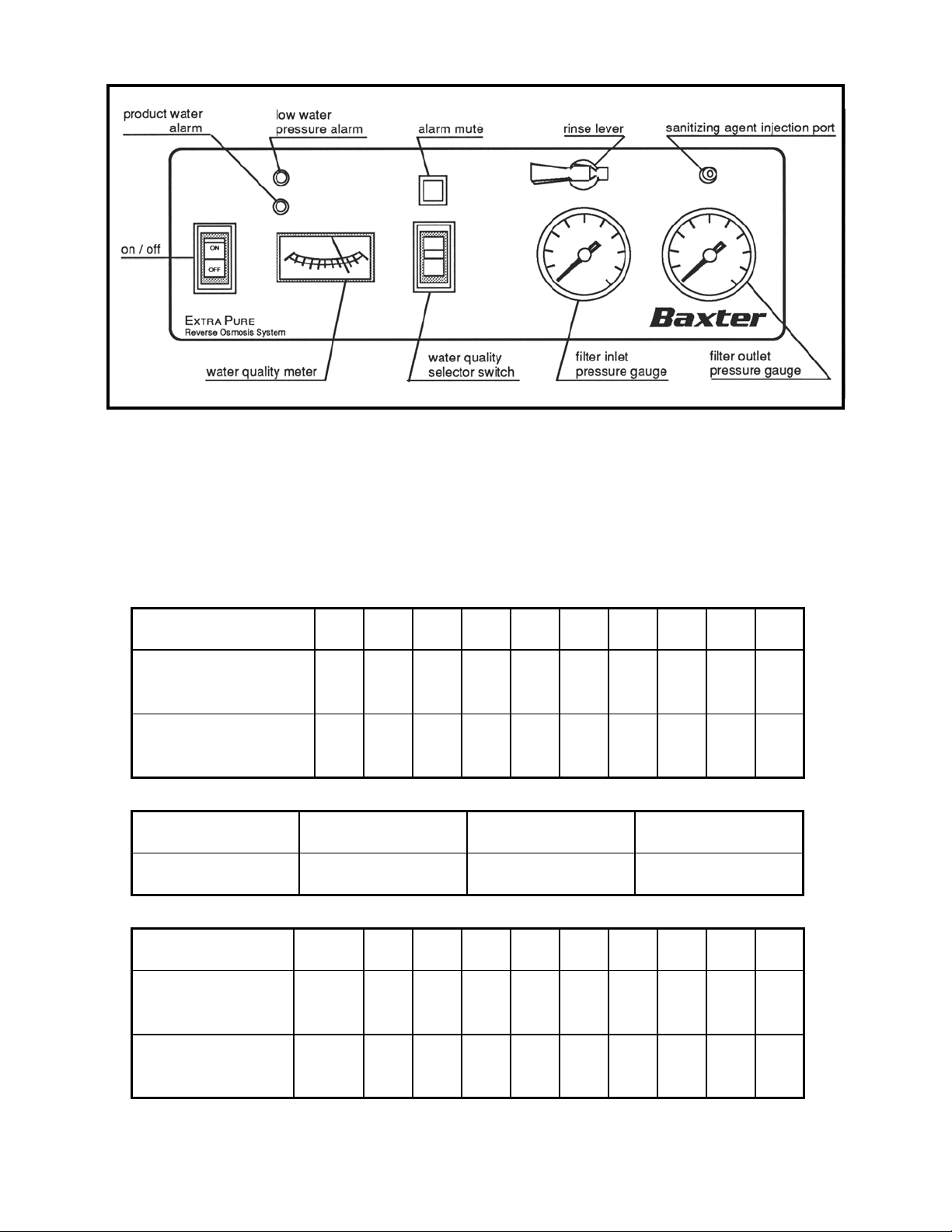
Operator's Controls
The filter inlet and filter outlet pressure gauges monitor the water pressure on both sides
of the incoming water filter. The pressure difference between the two gauges should
always be less than 10 psi. If the pressure difference is greater than 10 psi, the filter
must be changed.
The water quality meter monitors the quality of the water on the inlet and outlet side of
the reverse osmosis membrane and thus monitors the integrity of the RO membrane.
The green zone of the meter indicates that at least 90% of all dissolved solids are being
rejected by the RO membrane. The yellow zone shows 80 to 89% rejection. Less than
80% rejection (red zone) indicates that the reverse osmosis membrane needs to be
replaced.
WARNING:
Never operate the ExtraPure RO System with the needle in the red zone.
The three-position selector switch allows the meter to display the water quality of either
the recirculating water or the product water. Consult the water quality chart to
determine conductivity in microsiemens (µS/cm) and total dissolved solids in parts per
million (ppm).
The low water pressure alarm will activate when the incoming water pressure drops
below 5 psi. The product water alarm indicates that the output water to the dialysis
system has a conductivity of more than 118 µS/cm. The percent rejection alarm (needle
in the red zone) indicates that the RO membrane rejection is less than 80% and the RO
membrane may need replacement. Audible alarms can be silenced with the alarm mute
button. Also on the operator's control panel are the ON/OFF switch, the rinse lever, and
the sanitizing agent injection port.
5
Page 10
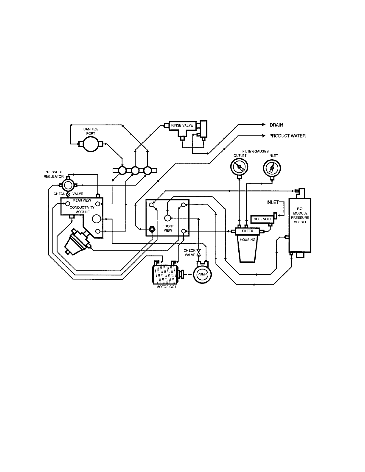
Figure 3: RO Flow Diagram
6
Page 11

Flow Diagram Component Identification
Component Purpose
Solenoid valve Opens to allow water to enter the RO. Closes when the unit is turned
off. It ensures that the disinfectant used in disinfecting the unit remains
inside the instrument until it is turned on again.
Water pressure
gauges
Filter Contains both a fiber material (5-10 micron) and activated carbon. The
Heat exchanger Tubing around the pump motor to cool the motor and warm the water.
Water pressure
regulator (20 psi)
Sanitize Luer port Used to inject disinfectant into the RO for sanitizing the machine.
Sanitize check valve Prevents back up of water or disinfectant through the sanitize Luer port.
Water pressure
switch
Thermistor Used to monitor the water temperature. This information is used in
Conductivity cells Used to measure the conductance of the recirculating and product
Procon pump Pump used in RO to push the water across the membrane. The pump
RO module Contains the thin film composite (TFC) membrane, which is the heart of
Test points Plugged holes in the system's flow block, which can be used by service
Pressure regulator
(200 psi)
Flow regulator A restrictor used to limit the flow of water to the drain during normal
Fast rinse valve Opened to create a high flow to drain when rinsing disinfectant from the
Check valve
(product line)
Located before and after the water filter. When the difference between
the two gauge readings is greater than 10 psi, the filter should be
changed.
carbon is sufficient for 13 treatments (for the home, about one month) if
the incoming water contains less than 3 ppm chloride ions. For higher
chloride levels and chloramines, additional activated carbon may
be needed.
This is done so the motor can be enclosed in insulation without
overheating and warmer water assists the membrane in producing
quality water.
Regulates the water pressure to the Procon pump at 20 psi.
Set at about 6 psi. Should the incoming pressure drop below this
amount, the Procon pump will be shut off and an alarm will sound.
conjunction with the two conductivity cells to determine the total ion
concentration of the recirculating and product water.
water. This information is combined to yield the display of percent
rejection on the front panel.
can produce pressures much higher than the 200 psi which is
necessary in the RO.
the system.
personnel to test pressures and set the pressure regulators.
Provides the backpressure necessary for the Procon pump to create
the 200 psi required to push water across the membrane.
function. The drain flow is about 1000mL/min.
system. This reduces the waiting time before the unit can be used.
Used to prevent incoming or recirculating water from entering the
product line. Because this valve is 1 psi, the output water pressure will
be 21 psi to the dialysis machine.
7
Page 12
Specifications
Name ExtraPure Reverse Osmosis System
Electrical supply 117 VAC 60/50 Hz or 230 VAC 60/50 Hz,
580 W, 6.5 A/3.3 A
Incoming water supply pressure 20-100 psi (138-690 kPa)
Filter 5-micron carbon filter (P/N 407-8502-014)
Maximum water hardness without
softening
Membrane configuration Spiral wound
Membrane material Thin film composite -- polyamide
Membrane pH tolerance of input water 3.0- 10.0
Operating temperature, minimum output
of 500 mL/min
Rated output at 25ºC (77ºF) input water
temperature
Rated output at 5ºC (41ºF) input water
temperature
Size unit Depth - 406 mm (16")
Weight 27 kg (60 lb)
RO membrane operating pressure 200 psi (1,380 kPa)
Depends on pH of feed water
5ºC to 35ºC (41ºF to 95ºF)
500 - 1,100 mL/min minimum
525 mL/min minimum
Width - 406 mm (16")
Height - 710 mm (28")
Membrane integrity/conductivity monitors Dual cell conductivity temperature
compensated, show % rejection and
absolute conductivity in microsiemens
Low water pressure alarm 5 psi (35 kPa)
Rejection of dissolved salts 90-98%
Rejection of organism (mol wt. greater
than 300), bacteria, pyrogens
Output pure water pressure 21 psi (145 kPa)
Disinfectant 37% aqueous formaldehyde or Hydrogen
Greater than 99%
Peroxide / Peroxyacetic Acid
depending on model.
8
disinfectant
Page 13

STARTUP
Water Supply
Every water supply is different and should be tested to determine the water treatment
required. Always have your water supply tested before connecting the ExtraPure RO
System. In some areas, water softening or other pre-treatment may be required.
Water Supply Requirements
Water supply: 7.5 liters per minute (2.2 gallons per minute) minimum
Pressure between 20 and 100 psi
Water temperature between 5ºC and 35ºC (41ºF and 95ºF)
Water pH between 3.0 and 10.0
Drain capability of 3 liters per minute (0.78 gallons per minute)
Negative test for scaling (Langlier saturation index)
Unpacking
After inspecting the shipping container for damage, open the box, remove all packing
materials, and inspect for damage. Report all damage promptly to the shipping
company and make a claim for compensation. Damage caused in shipment is not
covered by the equipment warranty. Save the shipping carton and packing material for
inspection and verification of your claim.
Inspect the ExtraPure RO System for leaks after unpacking. The ExtraPure RO System
is shipped with a new membrane, an input hose, a drain hose, a sanitize hose and a
new water filter.
The ExtraPure RO System must be disinfected prior to use. Follow procedures on page
16 and page 17 or according to your clinic’s recommendation.
9
Page 14

Installing
The ExtraPure RO System's hoses are shipped with caps on them.
Remove these caps before connecting the hoses.
1. Connect the input hose to the water supply. The
connection is a 3/4" female garden hose connection.
Use rubber washers on all connections.
2. Place the drain hose in the drain.
3. Connect the sanitize hose to the ExtraPure RO System
product water fitting (3/4" male garden hose) and place
the open end in the drain.
4. Check for proper voltage and then plug in the unit.
10
Page 15

Initial Rinse
1. Turn on the water supply. Check for
leaks. You should not hear water
running through the unit until it is
turned on.
2. Lift the rinse lever and turn on the
ExtraPure RO System with the
ON/OFF switch on the control panel.
Look for water flowing through the
drain line and sanitize hose.
3. Run the ExtraPure RO System for 15
minutes to rinse the fluid path.
RINSE!
After 15 minutes, turn off the unit to
install the filter in its blue housing.
Unscrew the housing counterclockwise and carefully remove it.
There will be water in the housing.
Empty the housing completely and
refill partially with fresh water. Then
slide the new filter into place and
reinstall the housing. The fresh water
in the housing prevents excessive air
in the fluid path.
After startup, never operate the
ExtraPure RO System without the
filter. Do not use any filter other than
the specified Baxter 5-micron carbon
filter (P/N 407-8502-014 or 5M1315).
4. Rinse the ExtraPure RO System by
lifting the rinse lever on the control
panel and letting the unit run for 15
minutes.
11
Page 16

5. Lower the rinse lever. After a few
minutes, water quality should be
normal and the water quality meter on
the control panel should read in the
green zone (above 90% rejection).
Product ____________
% Rejection _________
Recirculation ________
6. Use the three-position selector switch
on the control panel to determine the
values of the product and the
recirculation water. Write these down
for future reference. If the needle goes
off the right side of the scale, refer to
the Troubleshooting section of this
manual.
12
Page 17

Normal Operation
1. Rinse and then test for residual disinfectant according to your clinic's
recommendation before connecting the ExtraPure RO System to the dialysis
machine.
2. Turn on the water and turn on the ExtraPure RO System.
3. Note the filter pressure readings at the beginning of use. The difference between
filter/inlet pressure and filter/outlet pressure should always be less than 10 psi with
no water pressure alarm.
CAUTION:
The filter should be changed whenever the product water is below AMMI
Standards, the filter inlet/outlet pressure difference is greater than 10 psi, after 65
hours of operation, or as recommended by your clinic.
13
Page 18

Cleaning the Membrane
Note: This is not a sanitizing procedure. Follow procedures on page 16 or 17 to
sanitize the system.
1. Disconnect the product water line from the RO and install the sanitize hose. Place
the open end of this hose in the drain.
2. Inject 200-300 ml of white vinegar into the sanitization port. Turn the RO on, let the
machine run for 1 minute, then turn the machine off and let it stand overnight.
3. After allowing the vinegar to dwell overnight, turn the RO on and lift the rinse lever to
the rinse position. Rinse the machine for 15 minutes.
4. Check pH to verify all the vinegar has been flushed out of the RO. If pH is not in the
acceptable range continue the rinse until the pH is within limits.
5. Lower the rinse lever to the operating position and check the water quality meter to
ensure the needle is in the green zone. (If not the membrane will need to be
replaced.)
6. Turn the RO off.
7. Disconnect the sanitize hose from the RO and reconnect the product water line to
the RO.
8. Place the rinse lever in the run position.
The RO is now ready to be put back in service or to Sanitize as outlined on page 16 thru
19.
Filter Replacement
The ExtraPure RO System uses a disposable cartridge filter as illustrated in Figure 4.
The filter should be replaced if the product water is below AMMI Standards, if the
inlet/outlet pressure difference is more than 10 psi, or if the filter has been used more
than 65 hours (13 dialysis treatments).
1. Turn off the water to the unit.
2. Unplug the ExtraPure RO System.
3. To relieve the water pressure inside the unit, disconnect the water line to the dialysis
machine and place it in a clean bucket to avoid contamination.
4. Unscrew the blue filter housing (rear compartment of unit) by turning it
counterclockwise. The housing will have water in it. Pour off the water and set the
housing aside.
5. Remove and discard the old filter.
6. Replace with a new Baxter 5-micron carbon filter (P/N 407-8502-014 or 5M1315).
DO NOT USE ANY FILTER OTHER THAN THE FILTER SPECIFIED. Partially fill
the housing with fresh water to prevent excessive air in the fluid path. Then slide the
filter into place and carefully reinstall the housing.
7. Turn on the water supply and plug in the ExtraPure RO System. Run the unit for 15
minutes with the rinse lever on the control panel in the rinse position. After rinsing,
return the rinse lever to the normal operating position.
14
Page 19

Figure 4: Filter assembly
15
Page 20

SANITIZATION
Sanitizing a Formaldehyde RO and Storage Procedure
WARNING: Store all Disinfectants out of reach of children
1. The ExtraPure RO System should be sanitized at least once a week with regular
use, or follow your clinic's recommendation, to prevent bacteria building up in the
water path. Use only 37% aqueous formaldehyde solution (Formalin™).
2. With the unit off, disconnect the water line connecting the ExtraPure RO System to
the dialysis machine. In its place, connect the sanitize hose. Place the end of the
sanitize hose in the drain. Ensure the drain hose is in the drain.
3. Carefully inject 100 cc Formalin™ into the disinfectant port. Slowly inject the
Formalin™ into the disinfectant port on the control panel. Then inject 50 cc water
and reinstall the sanitize cap.
4. Turn on the unit and let it run for 30 - 45 seconds with the rinse lever in the operating
position. (If storage time will be more than three days, remove filter and housing,
and allow to air-dry.
5. Turn off the ExtraPure RO System and turn off the feed water. Let the RO unit stand
with the Formalin™ disinfectant in it until rinsing, according to your dialysis regimen
and your clinic's recommendation. (If storage time will be more than three days,
remove filter and housing, and allow to air-dry.)
6. Rinse the Formalin™ solution from the RO for at least 15 minutes with the rinse
lever in the up position. Rinse until output water tests negative for Formalin™
residuals according to your clinic's procedures. See page 19.
7. Turn off the ExtraPure and the feed water. Disconnect the sanitize hose and
reconnect the product water line to the dialysis machine.
NOTE
In a 7-day period, a typical dialysis regimen will have one
interval between treatments longer than the other interval(s).
For convenience, this longer interval can incorporate the
sanitization of the ExtraPure RO System. For example, in
the dialysis schedule shown, with treatments on Monday,
Wednesday, and Friday, sanitize the ExtraPure RO System
after dialysis on Friday and rinse the unit before dialysis on
Monday.
S
6
13
20
27
M
7
14
21
28
T
1
8
15
22
29
W
2
9
16
23
30
T
F
3
4
10
11
17
18
24
25
31
S
5
12
19
26
16
Page 21

Sanitizing a Hydrogen Peroxide/ Peroxyacetic Acid
Disinfectant Compatible Reverse Osmosis System
CAUTION:
Make sure the device you will be using is model 5M5509 or FM4644. Use of
Hydrogen Peroxide and Peroxyacetic Acid in a non-compatible machine will
cause premature deterioration of components. The ExtraPure RO System should
be disinfected with Formaldehyde if the system will sit idle for more than seven
days. Refer to page 16 "Sanitizing a Formaldehyde RO and Storage Procedure."
The ExtraPure RO System should be sanitized at least twice a week with regular
use, or follow your clinic’s recommendation, to prevent bacteria building up in the
water path. Use 100% disinfectant that is made with 22% Hydrogen Peroxide and
4.5% Peroxyacetic Acid.
Minntech® manufactures a product called Minncare® for this purpose.
WARNING: Store all Disinfectants out of reach of children.
1. With the unit off, disconnect the water line connecting the ExtraPure RO System to
the dialysis machine. In its place, connect the sanitize hose. Collect at least 50 cc of
product water from the sanitizing hose. This product water will be used in step 2.
Then place the end of the sanitize hose in the drain. Ensure the drain hose is in the
drain.
2. Carefully inject 60 cc of Hydrogen Peroxide/ Peroxyacetic Acid into the disinfectant
port on the control panel, and then inject 50 cc of the product water collected in step
1. Reinstall cap on sanitize port.
3. Verify the rinse lever is in the operating position. Turn on the unit and let it run for 30
to 45 seconds.
17
Page 22

4. Turn off the ExtraPure RO System and turn off the feed water. Let the RO unit stand
idle until rinsing, according to your clinic’s recommendation. The disinfectant must
dwell in the system for two hours.
Notice: Damage to the system may result if the dwell time is longer than two
hours and the membrane is fouled by one of the following conditions: 1. Heavy
metals in the water source such as iron 2. Inorganic matter in the water source 3.
The pH level is higher than 5.
5. Rinse the Hydrogen Peroxide/ Peroxyacetic Acid solution from the RO for at least 15
minutes with the rinse lever up. Rinse until output water tests negative for Hydrogen
Peroxide/ Peroxyacetic Acid residuals according to your clinic’s recommendation. See
the next page.
CAUTION: The Hydrogen Peroxide / Peroxyactic Acid should never dwell in the
system longer than twelve hours. For long-term storage follow the procedure
using Formaldehyde.
18
Page 23

Rinsing
WARNING:
After sanitizing, you must rinse the ExtraPure RO System before using it to
supply dialysis water.
1. Turn on the feed water.
• Lift the rinse lever on the control panel to the RINSE position.
• Turn on the ExtraPure RO System.
• Let the ExtraPure run for at least 15 minutes.
2. After 15 minutes rinsing, test the product water (sanitize hose) for residual
disinfectant according to your clinic's recommendation. Continue rinsing until the
test is negative.
3. When the test for disinfectant is negative, place the rinse lever in the OPERATE
position. The ExtraPure RO System is ready for operation when the water quality
meter reads in the yellow or green zones.
4. Turn off the ExtraPure RO System and the feed water.
5. Remove the sanitize hose and reconnect the product water line to the dialysis
machine.
19
Page 24

MAINTENANCE
Required periodic maintenance includes inspections for leaks, cleaning, sanitation, and
filter replacement.
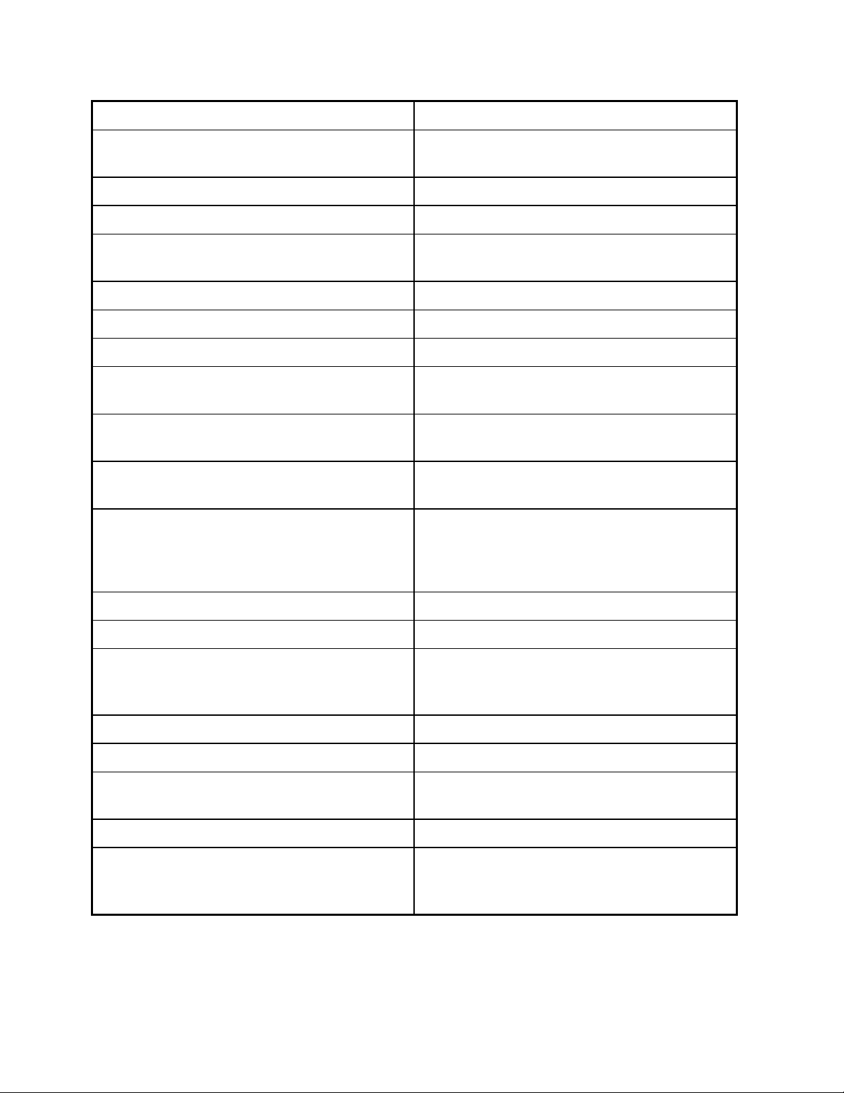
Recommended Tools to Maintain One ExtraPure RO
Tool Part Number
Hach Water Test Kit 413-0001-026
Myron L Total Dissolved Solids Meter 499-4000-032
0-30 psi gauge 403-8500-004
0-400 psi gauge 403-8500-009
Filter Wrench 413-0001-013
Recommended Spare Parts to Maintain One ExtraPure RO for
One Year
Catalog
Page #
1 3 407-8502-014 Charcoal Filter, 5 micron As needed
3 35 908-5000-176 RO Filter Element 1
4 7 157-1232-255 Sanitizing Port Cap 1
4 23 402-9862-132 Sanitizing Port Female Luer-Lok 1
Item Part Number Description Quantity
Inspection for Leaks
Before each dialysis treatment, check for leaks at the hose connections, filter housing,
and cabinet assembly. If leaks cannot be corrected, call Baxter Instrument Services
1-800-553-6898.
External Cleaning
Clean the outside of the ExtraPure RO System cabinet with a solution of water and a
mild detergent. If additional cleaning is needed, use a solution of half water and half
household bleach.
20
Page 25

TROUBLESHOOTING
Basic troubleshooting procedures are given below. If these procedures do not correct
the problem, call Baxter Instrument Services at 1-800-553-6898.
Alarms
SYMPTOM PROBABLE CAUSE CORRECTIVE ACTION
Product alarm High product TDS caused by a
torn membrane.
High product TDS caused by
an occluded drain orifice. (No
flow at drain when rinse valve
is down.)
Low pressure alarm Water not turned on.
The filter needs to be changed.
20 psi regulator is not properly
adjusted
Water pressure switch is
broken
Change the membrane.
Clean the drain orifice or
change the flow controller
assembly.
Turn on the water.
Check filter gauges.
Change filter if necessary.
Install a gauge in the proper
port; adjust the regulator.
Replace the switch.
Electrical
SYMPTOM PROBABLE CAUSE CORRECTIVE ACTION
Motor does not run ON/OFF reset switch in back of
the machine set at OFF.
Fails electrical
leakage test
Unable to adjust +12
Volts to +
Unable to adjust -12
Volts to + 0.1 VDC
0.1 VDC
Power supply, power cord,
pump/motor, and wiring.
Power supply Replace or call Baxter
Power supply Replace or call Baxter
Switch to ON.
Replace or call Baxter
Instrument Services.
Instrument Services.
Instrument Services.
21
Page 26

SYMPTOM PROBABLE CAUSE CORRECTIVE ACTION
Moisture around
conductivity cell
electrodes
With water off, no
alarms & pump runs,
or mute inoperative
Meter indication or
logic inaccurate
RO recirculation cell is
< 10 X RO product
cell
Electrodes Replace or call Baxter
Instrument Services.
PCB, pressure switch, wiring,
alarm mute switch, inlet.
Meter, PCB, thermistor, wiring,
3 position switch, product water
LED, Sonalert alarm,
conductivity cells
Meter, PCB, power supply,
electrodes, thermistor, RO
module or vessel, filter, wiring
Replace or call Baxter
Instrument Services.
Clean, calibrate or replace
as necessary, or call Baxter
Instrument Services.
Clean, calibrate or replace
as necessary, or call Baxter
Instrument Services.
Flow
SYMPTOM PROBABLE CAUSE CORRECTIVE ACTION
Proper input water
pressure, but no
output
Unable to regulate
product flow to 500
mL/min
Unusual noise coming
from the pump
Water running out of
the cabinet
Drain flow < 800
mL/min
Product flow <1100
mL/min
Drain flow w/fast rinse
switch up <1500
mL/min
Pump motor not running, motor
overload protector stopping
motor.
PCB, power supply, pressure
switch, power cord, relay,
pump/motor, RO
module/vessel, low pressure
regulator, wiring, inlet water
solenoid, on/off SW/CRT
breaker
Filter partly clogged and not
supplying enough water.
Pump pressure to RO
membrane low.
Leak inside the unit. Look for loose connections.
Pump or motor, RO module or
vessel
Pump or motor, RO module or
vessel, Inlet water temperature
is below 25º C.
Pump or motor, RO module or
vessel. Fast rinse switch block
Verify that the conductivity
cell connection is secure.
Check motor connections.
Calibrate or replace as
necessary, or call Baxter
Instrument Services.
Change the filter.
Replace pump head or call
Baxter Instrument Services.
Tighten or repair with Teflon
tape or silicon RTV. If
unable to repair, call Baxter
Instrument Services.
Replace or call Baxter
Instrument Services.
Replace or call Baxter
Instrument Services.
Replace or call Baxter
Instrument Services.
22
Page 27

Pressure
SYMPTOM PROBABLE CAUSE CORRECTIVE ACTION
Output water pressure
low
Water pressure
gauges vibrate
Difference between
water inlet/outlet
gauges > 10 psi
Reverse Osmosis membrane
aged, capacity has fallen below
specification due to use and
scaling.
Pump pressure to RO
membrane low.
Incoming water pressure is too
high.
Filter, pressure gauges Replace filter/gauges or call
RO membrane will need to
be cleaned or replaced.
Call Baxter Instrument
Services.
Replace pump head or call
Baxter Instrument Services.
Install an incoming water
pressure regulator.
Baxter Instrument Services.
Water Quality
SYMPTOM PROBABLE CAUSE CORRECTIVE ACTION
Water quality as
indicated on the water
quality meter is in the
red zone (below 80%
rejection)
Water quality not in
green, but quality is
good
Water quality meter
reads off the right side
of the scale
This condition can be caused
by a number of related
conditions:
1. Failure of the RO
membrane.
2. Degradation of the RO
membrane but not a membrane
leak.
3. Flow and pressure
conditions within the unit have
changed so that the % yield
has increased significantly.
Meter, PCB, power supply,
electrodes, thermistor, RO
module/vessel, filter, wiring
Open electrical connection in
conductivity circuit.
Do not operate with water
quality meter in the red
zone. Call Baxter
Instrument Services.
Check conductivity reading
with the three-position
switch.
Call Baxter Instrument
Services
Clean, calibrate or replace
as necessary, or call Baxter
Instrument Services.
Call Baxter Instrument
Services.
23
Page 28

SYMPTOM PROBABLE CAUSE CORRECTIVE ACTION
% rejection indicator is
in the red zone,
audible alarm.
% rejection indicator is
in the red zone but
there is no audible
alarm.
Product water chlorine
exceeds AMMI
Standards
Incoming TDS is less than 150
ppm (calculated % rejection is
less than 80%).
Membrane is scaling.
Internal water pressure
regulators are not set properly.
Drain orifice is occluded.
Meter is not calibrated.
% rejection offset is not
calibrated.
Filter may be saturated with
chlorine.
Install a 5K resistor in
parallel with the
recirculation conductivity
cell.
Inject 200-300 ml white
vinegar into the sanitization
port, let the unit run for 1
minute, then let it stand
overnight.
Install gauges in the ports
provided, then set the
product and recirculation
regulators at 20 psi and 200
psi, respectively.
Clean the drain orifice or
replace the flow controller
assembly.
Calibrate the meter.
Calibrate the % rejection
offset.
Change the carbon filter.
24
Page 29

Calibration of Electronics
CAUTION: The following procedure should only be performed by a qualified
technician. Call Baxter Instrument Service at 1-800-553-6898.
% Rejection Meter Adjustment R55: For the recirculation cell, substitute a 4K resistor
(10% or better). For the product cell, substitute a 20K resistor. Adjust R55 so that the
meter rests on the red-yellow border.
% Rejection Meter Adjustment R56: With the same resistors in place, connect the
voltmeter to TP2. Adjust R56 for the point at which the voltage changes from low to
high. You will not be able to use the LED as a reference due to the delay.
Product Alarm Adjustment R44:
1. Short out the recirculation cell.
2. Substitute 11.2K resistor for product cell.
3. Hook voltmeter to TP1.
4. Adjust R44 for point at which voltage changes from low to high.
NOTE
This adjustment is sensitive to ambient thermistor temperature.
You will not be able to use the LED as a reference due to the delay.
Monitor Check: With the 4K and 20K resistors in place as in the first calibration, you
should be able to get the following readings on the water quality meter.
Product 1.5 - 3.5
Recirculation 4.0 - 6.0
% Rejection on red-yellow border
This will confirm conductivity PCB operation. If meter readings do not agree with
laboratory analysis, check the thermistor (10K resistance) and the cells.
Replacing the RO Membrane
CAUTION: The following procedure should only be performed by a qualified
technician. Call Baxter Instrument Service at 1-800-553-6898.
1. Turn off the RO and disconnect it from the water source and electrical outlet.
2. From the back of the unit, open the straps at the top and bottom of the vessel.
3. Once the pressure vessel is loose, lift it out of the bracket and lay it on its side on
something (such as a wastebasket) to catch the water that will be draining out of the
vessel.
4. Remove the compression fitting on the input water line located about 4" from the
bottom of the vessel. Remove this fitting slowly. There still may be pressure in the
line.
25
Page 30

5. Using a flat blade screwdriver, remove the top snap-ring holding the top cap in
place. Slowly pull the cap out of the top of the vessel using a rocking motion.
6. Remove the bottom snap-ring and end cap as in previous step. (This step is not
necessary if you are able to remove the membrane through the top without
difficulty.)
7. Remove the old membrane by pushing from the bottom or pulling from the top of
the vessel.
8. Unpack and inspect the new membrane. The end with the U cup brine seal is the
bottom of the membrane. Make sure the open side of the U cup brine seal faces
upward toward the top.
9. Insert the new membrane into the vessel from the top. The U cup brine seal will
allow the membrane to be inserted only in one direction. The bottom of the
membrane inserts into the top of the vessel. If the membrane is difficult to insert,
inspect the U cup brine seal to be sure it is oriented properly.
10. Replaced the two o-rings on the top and bottom end caps. (The part numbers for
the o-rings are 408-8500-005 for the small o-ring and 408-8500-004 for the large oring.) After installing the o-rings, apply a light coat of high vacuum grease (part
number 594-0001-019) to the o-rings.
11. Reinstall the top and bottom end caps and snap-rings, being careful not to damage
the 0-rings. Make sure the snap-rings are set in their respective grooves in the
vessel.
12. Reinstall the vessel into the straps.
13. Connect the input water supply line to the vessel.
14. Turn on the unit long enough to let the vessel pressurize. You will notice the end
caps move when the pressure builds up.
WARNING: Do not stand directly above the RO while turning it on. If the snaprings are not seated correctly, the end cap may fly off.
15. Check for leaks.
16. Return equipment to operation after sanitizing and rinsing.
17. Confirm the water quality prior to use.
26
Page 31

A
AA
B
BB
Pressure Adjustments for Hydrogen Peroxide/Peroxyacetic Acid
Compatible System
CAUTION: The following procedure should only be performed by a qualified
technician. Call Baxter Instrument Service at 1-800-553-6898.
1. Remove hole plugs in the conductivity cell block while the RO unit is off.
2. Install:
"AA" 0-30 psi gauge in the below recirculation cell.
"BB" 0-400 psi gauge in the hole on the high pressure regulator.
3. Turn the RO unit on and restrict product water flow to 500 cc/min.
"A" verify recirculation pressure is 21 to 24 psi. If not, adjust the low pressure
regulator located above the block.
"B" verify RO module pressure is 200 psi. If not, adjust pressure using the
high pressure regulator.
4. Remove gauges and replace the hole plugs.
27
Page 32

AAA
BB
B
Pressure Adjustments for Formalin™ Compatible System
CAUTION: The following procedure should only be performed by a qualified
technician. Call Baxter Instrument Service at 1-800-553-6898.
1. Remove hole plugs in the conductivity cell block while the RO unit is off.
2. Install:
"AA" 0-30 psi gauge in the below recirculation cell.
"BB" 0-400 psi gauge in the hole on the high pressure regulator.
3. Turn the RO unit on and restrict product water flow to 500 cc/min.
4. At point "A" verify recirculation pressure is 21 to 24 psi. If not, adjust the low
pressure regulator located above the block.
At point "B" verify RO module pressure is 200 psi. If not, adjust pressure using the
high pressure regulator.
5. Remove gauges and replace the hole plugs.
28
Page 33

Conductivity Cell Connections
Damage or loosening of these connections could render the conductivity cell useless
and result in erroneous water quality readings. The following are results obtained by
simulating conductivity cell failure.
Conditions % Rejection Product Recirculation
Product cell open pegged right pegged right normal
Recirculation cell
open
Both cells open lower, still in green
pegged left slightly high, still in
green scale
pegged right pegged left
scale
pegged right
29
Page 34

DIAGRAMS AND SCHEMATICS
The following diagrams and schematics are contained in this section:
ExtraPure RO Wiring Diagram, 157-1232-996
ExtraPure RO System Schematic Diagram, 157-1232-997
Logic-Conductivity Circuit, 157-1232-994
30
Page 35

31
Page 36

32
Page 37

33 34
Page 38

Page 39

 Loading...