

Baxter DPC1S Service Manual

SERVICE MANUAL
INSTALLATION INSTRUCTIONS
DEHUMIDIFYING PROOFING
CABINET
DPC1S ML-132526
- NOTICE -
This Manual is prepared for the use of trained Baxter Service
Technicians and should not be used by those not properly
qualified.
This manual is not intended to be all encompassing. If you have
not attended a Baxter Service School for this product, you should
read, in its entirety, the repair procedure you wish to perform to
determine if you have the necessary tools, instruments and skills
required to perform the procedure. Procedures for which you do
not have the necessary tools, instruments and skills should be
performed by a trained Baxter Service Technician.
The reproduction, transfer, sale or other use of this Manual,
without the express written consent of Baxter, is prohibited.
This manual has been provided to you by ITW Food Equipment
Group LLC ("ITW FEG") without charge and remains the property
of ITW FEG, and by accepting this manual you agree that you will
return it to ITW FEG promptly upon its request for such return at
any time in the future.
A product of Baxter MFG. Co., Inc 19220 State Route 162 East Orting, WA 98360
F45509 (0813)

INSTALLATION INSTRUCTIONS DEHUMIDIFYING PROOFING CABINET
TABLE OF CONTENTS
GENERAL .................................................................................................. 3
INTRODUCTION ....................................................................................... 3
UNPACKING ........................................................................................... 3
LOCATION ............................................................................................. 3
CLEARANCE DIMENSIONS ............................................................................ 3
TOOLS ................................................................................................. 3
BASIC CABINET CONSTRUCTION ..................................................................... 4
WALL CONFIGURATIONS ............................................................................. 5
PREASSEMBLED CABINETS .............................................................................. 6
POSITION CABINET ................................................................................... 6
FLOOR ................................................................................................. 6
FLOOR BRACKETS .................................................................................... 7
ELECTRICAL SUPPLY CONNECTION .................................................................. 8
FINAL CHECKS ........................................................................................ 9
UNASSEMBLED CABINETS .............................................................................. 10
WALL PANEL ......................................................................................... 10
CEILING PANELS ..................................................................................... 10
FLOOR ............................................................................................... 10
FLOOR BRACKETS ................................................................................... 11
AIR DUCT ASSEMBLY ................................................................................ 12
DRAIN ................................................................................................ 13
AIR INTAKE & INTERMEDIATE PANEL ............................................................... 13
BUMPERS ............................................................................................ 14
INTERIOR DIFFUSER DUCT .......................................................................... 15
DOOR HANDLE ....................................................................................... 16
DOOR HINGES ....................................................................................... 16
DOOR MAGNET ...................................................................................... 17
COMPONENT & JUNCTION BOX ..................................................................... 17
REAR VENT .......................................................................................... 17
WATER SUPPLY LINE CONNECTION ................................................................ 19
TRIM PANELS ........................................................................................ 19
CONTROLLER TO COMPONENT BOX CONNECTION ................................................ 20
ELECTRICAL SUPPLY CONNECTION ................................................................ 22
FINAL CHECKS ....................................................................................... 23
© BAXTER 2013
F45509 (0813) Page 2 of 23

INSTALLATION INSTRUCTIONS DEHUMIDIFYING PROOFING CABINET - GENERAL
GENERAL
INTRODUCTION
These instructions are for Baxter DPC1S
dehumidifying proofer. The DPC1S 40.5 inch deep
cabinet can be shipped assembled requiring minimal
field assembly. This cabinet can also be shipped
unassembled requiring field assembly. Both shipping
methods will require leveling and connection to
utilities. All utility connections are the responsibility of
the customer. All information, illustrations and
specifications contained in this manual are based on
the latest product information available at the time
indicated on the cover of the manual. Retain these
instructions for future reference.
UNPACKING
Remove crating from cabinet and check for possible
shipping damage. If cabinet is found to be damaged
after un-crating, save packaging material and contact
the carrier within 15 days of delivery. If location has
multiple cabinets, keep serial numbered crates
together. Check contents against packing list with
shipment. Refer to hardware list for identifying
hardware usage.
Cold water.
• Water Quality:
Hardness 2-4GPG. pH 7.0 to 8.0.
Chloride concentration 0-30ppm.
Sediment <.5 micron.
Turbidity <.5NTU.
Total dissolved solids <400ppm.
• The electrical diagram is located on the cover of
the component box. Cabinets requires a single
phase or three phase 208-240 volt electrical
connection. Neutral wire circuitry needed to
provide 110-120 volt for miscellaneous control
components. A separate 110-120 volt line may
be run or a transformer option will be required if
110-120 volt is not available. Consult Bakery
Product Support for 110-120 volt line or
transformer option requirements.
• Single Phase (L1,L2, Neutral, Ground).
• Three Phase (L1,L2,L3, Neutral, Ground).
CLEARANCE DIMENSIONS
LOCATION
• Level floor within 1/8" per foot up to 3/4" in all
directions.
• Drain connection:
1/2" NPTF rear or front drain connection at
5" above finished floor, route to air gap
drain.
• Water connection:
Water and waste piping and connections
shall comply with the International Plumbing
Code 2003, International Code Council
(ICC), or to the Uniform Plumbing Code
2003, International Association of Plumbing
and Mechanical Officials (IAPMO).
NOTE: Plumbing connections must comply with
applicable sanitary, safety and plumbing codes and
provide adequate backflow protection to comply with
applicable federal, state and local codes.
1/2" NPTF water line connection at 95"
above finished floor.
30-80 psi flow.
Cabinets UL/CSA Listed for 0" clearance for back and
side walls.
A 2" to 4" back clearance is recommended when
plumbing rear drain connection.
Top of cabinet requires a minimum of 24" clearance
for servicing accessability.
Side wall(s) require a minimum of 1" clearance for
better performance if the DPC1S cabinet is installed
next to an oven.
TOOLS
Standard Tools
• Standard set of hand tools.
• VOM with AC current tester.
• Tile Trowel (square notch) Grainger No. 5LG06
supplied with floor option proofer.
Special Tools
• Hammer drill 1/2" Grainger No. 3TB72 to drill
holes in floor for anchor bolts.
• 3/8" masonry drill bit to drill holes in floor for
anchor bolts.
Page 3 of 23 F45509 (0813)

INSTALLATION INSTRUCTIONS DEHUMIDIFYING PROOFING CABINET - GENERAL
• Setting tool Part No. 01-1000V4-73A to set dropin anchors in facility floor supplied with proofer
hardware.
• Roller Tool (Laminate J Roller) - for completing
seal of floor trim to wall.
• 7/32" hex socket 3/8" drive Grainger No. 3LB97.
BASIC CABINET CONSTRUCTION
• 5/16" hex key 6" long Grainger No. 4RE58 to lock
cam locks.
• Handheld, digital temperature and humidity
sensor Grainger No. 4ZG11.
Fig. 1
F45509 (0813) Page 4 of 23

INSTALLATION INSTRUCTIONS DEHUMIDIFYING PROOFING CABINET - GENERAL
WALL CONFIGURATIONS
The right side wall will always be the solid wall. The
left side wall will contain the proofing system.
DPC1S Cabinet Witdh = 42.00"
Fig. 2
Page 5 of 23 F45509 (0813)
INSTALLATION INSTRUCTIONS DEHUMIDIFYING PROOFING CABINET - PREASSEMBLED CABINETS
PREASSEMBLED CABINETS
Cabinet can be shipped assembled. You may want to remove door(s) prior to maneuvering cabinet into place. Each
cabinet is shipped with the individual parts needed for on site assembly along with a packing list. Before installing
cabinet, compare parts to packing list to ensure all parts were received. Wait as long as possible before removing
plastic protective covering from panels. Apply silicone between floor and wall angle or floor and base channel seams.
Leave no voids.
POSITION CABINET
NOTE: If cabinet rear drain is not accessible from the
back when in final location, route the proofer drain
outside of the cabinet to the facility drain before setting
proofer in final location.
1. Position cabinet near the final location.
2. Determine if the drain must be routed out the
back or front of the unit.
A. If the drain is not accessible with the unit in
the final location, install drain prior to moving
unit into final location.
3. Position cabinet in final location and level.
A. If necessary, place shims under walls to
level cabinet.
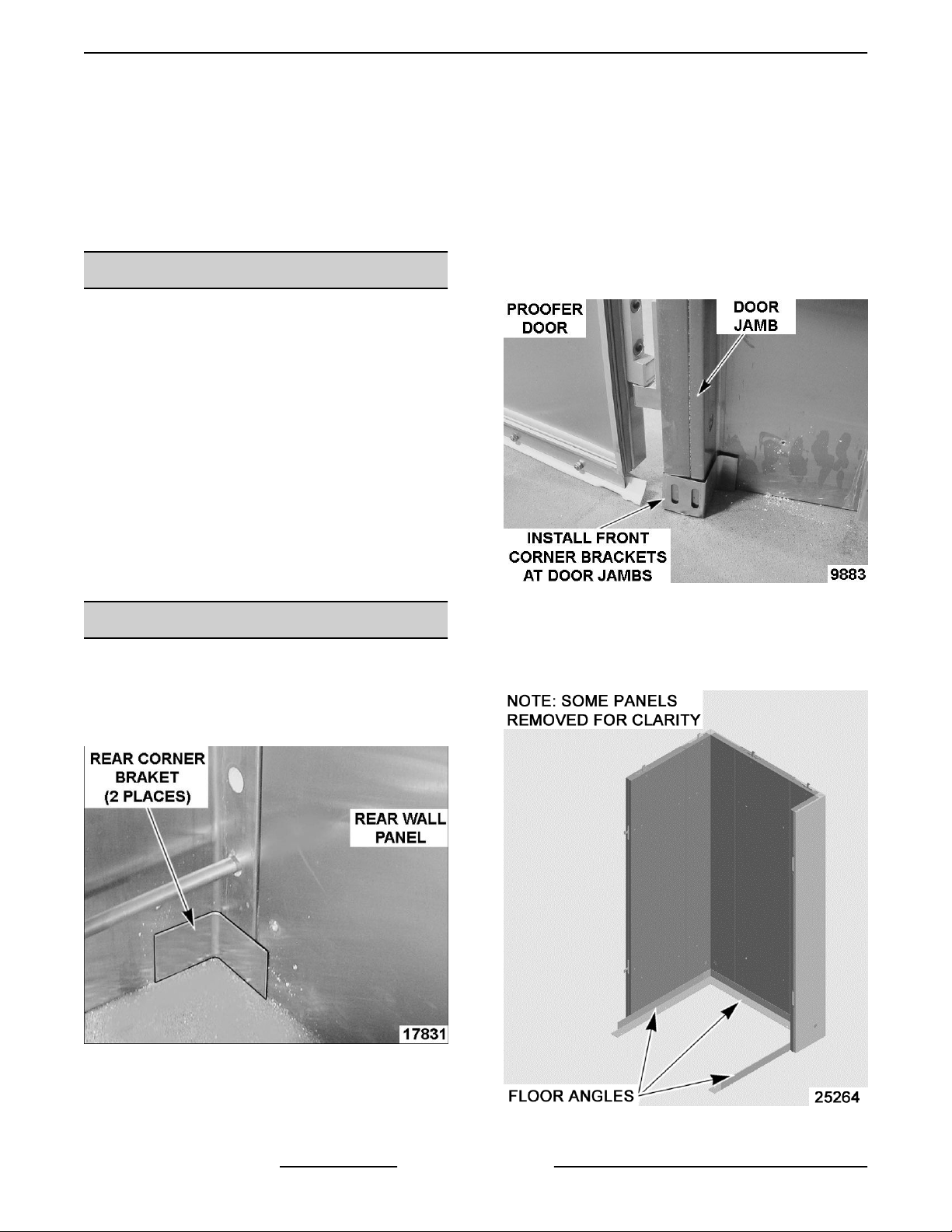
FLOOR
1. Install rear corner brackets at both rear corners
of cabinet.
NOTE: Place a spot of silicone on back side of
brackets to aid in holding brackets into position.
NOTE: Place a spot of silicone on back side of
brackets to aid in holding brackets into position.
Fig. 4
3. (Cabinet No Floor option only) Check walls for
squareness and Install floor angles.
NOTE: Do not use floor angles on cabinets with floor.
Fig. 3
2. Install front corner brackets at bottom of door
jambs.
F45509 (0813) Page 6 of 23
Fig. 5
INSTALLATION INSTRUCTIONS DEHUMIDIFYING PROOFING CABINET - PREASSEMBLED CABINETS
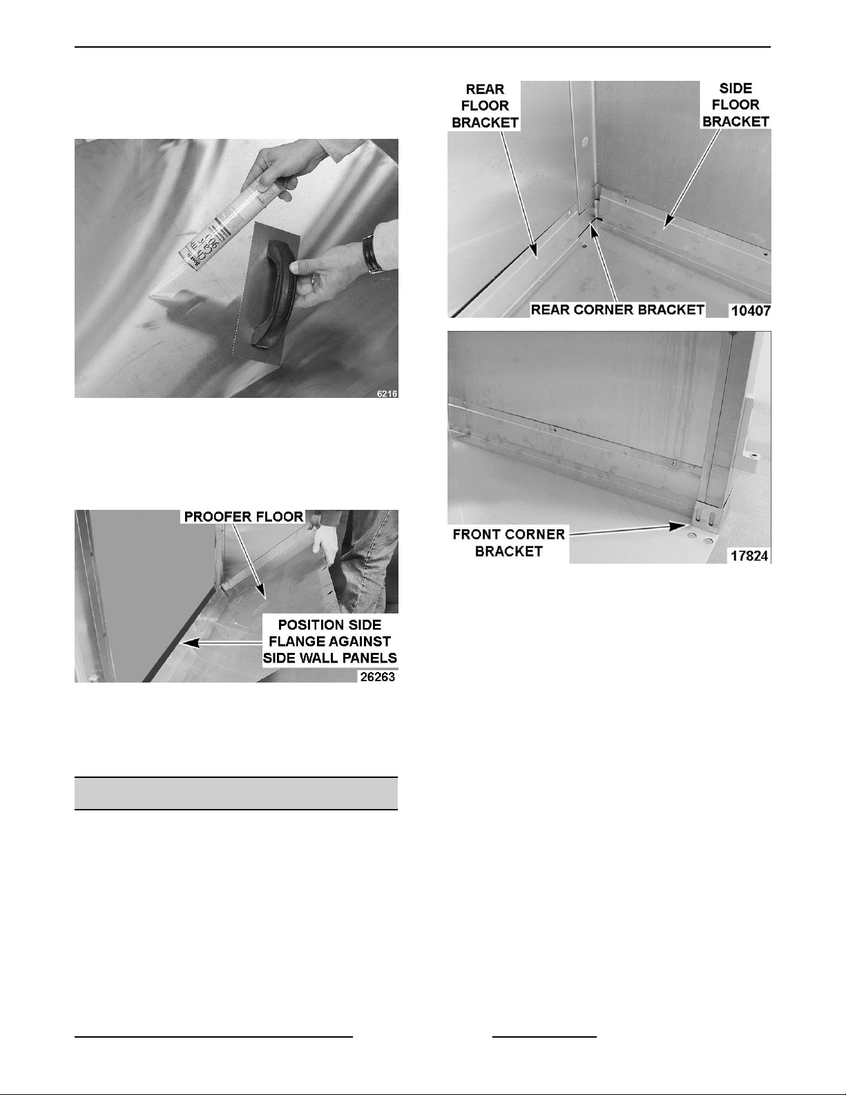
4. Apply adhesive to bottom of floor and spread
evenly with a trowel. Cover entire floor surface
with adhesive.
Fig. 6
5. Place cabinet floor in final position.
A. Position left hand side flange of single piece
cabinet floor such that side flange is behind
air duct.
Fig. 7
6. Anchor cabinet floor to facility floor.
7. Check proofer for being level. If necessary, place
shims under cabinet walls to level.
FLOOR BRACKETS
1. Install floor brackets to cabinet walls.
NOTE: Ensure front and rear corner brackets are in
the gap between cabinet floor and wall.
Fig. 9
2. Silicon front and rear corner brackets to cabinet
floor and wall panels.
NOTE: One floor bracket for each side wall and one
for the rear wall.
3. Level and square door. Install door jamb
mounting brackets to front cabinet corners and
secure to facility floor.
NOTE: If mounting bracket holes do not line up with
clearance holes in floor, drill new clearance holes.
4. If door removed earlier, install door onto door
hinges.
Page 7 of 23 F45509 (0813)
 Loading...