

Page 1
E
C
X
E
X
C
Operator’s Manual
E
C
X
E
X
C
.
E
C
X
E
X
C
C
O
L
L
E
A
G
U
E
G
U
A
R
D
I
A
N
PRODUCT CODES: 2M91617 and 2M91637
A
E
G
L
U
L
E
O
C
G
N
U
A
A
I
R
D
.
E
X
C
C
X
E
Prior to using this pump, read this manual carefully to fully understand
the pump’s functionality and to ensure safe and proper operation.
071960491
Page 2

!
WARNING
!
There are risks associated with using anything other than the recommended sets with this
device. Sets designated for use with this device are identified in “Recommended Administration
Sets,” 4-15. Baxter’s warranty on this device will be null and void and Baxter will assume no
responsibility for incidents which may occur if the product is not used in accordance with
product labeling.
Computer Software Copyrights
©Copyright 1996 – 2010, Baxter Healthcare Corporation. All rights reserved.
For use only by Baxter Healthcare Corporation. The software contains proprietary information belonging to Baxter
Healthcare Corporation. The software must not be reproduced or disclosed to others without prior written approval.
Any unauthorized use of this information may subject the user to substantial liability.
Documentation Copyrights
Duplication or distribution of this manual and any information contained within is strictly prohibited without the
express written permission of Baxter. This manual and any information contained within, may not be reproduced,
distributed, or transmitted in any form, or by any means, for any purpose, without the express written permission of
Baxter. To order additional copies of this manual, or other related manuals, contact your local Baxter Service Center.
Disclaimer
The information in this document has been carefully examined and is believed to be entirely reliable. However, no
responsibility is assumed for inaccuracies. Furthermore, Baxter reserves the right to make changes to any products
herein to improve readability, function, or design. Baxter does not assume any liability arising out of the application
or use of any product or circuit described herein; neither does it cover any license under its patent rights nor the rights
of others.
Trademark Information
Baxter, Buretrol, Colleague, Colleague Guardian, Continu-Flo, and Personality are trademarks of Baxter International
Inc. Other trademarks/products appearing herein are the property of their respective owners.
Patent Information
This device is protected under one of more of the following U.S. and foreign patents: United States: 5151019,
5764034, 5779207, 5782805, 5842841, 6013057, 6123524, D390654, RE37074E, 2004/0193325A1; Australia:
130693, 706187, 710286, 712859, 713132, 721076, 740655; Austria: E248618, E255925; Belgium: EP0833674,
EP0836492, EP0837708, EP0891784; Canada: 2223838, 2223841, 2223897, 80218; Denmark: 165/97,
EP0833674, EP0836492, EP0837708, EP0891784; European Patent Convention: EP0833674; Finland:
EP0836492, EP0891784; France: EP0426273, EP0833674, EP0836492, EP0837708, EP0891784, EPO931555;
Germany: 69013289.1, 69720637.8, 69724600.0, 69726089.5, 69726683.4, 69731650.5, M9608875.3; Greece:
20030404616, 20040400581; Hong Kong: 1002288, 1002294, 1026249, 1026250, HK1002291, HK1002353;
Ireland: EP0836492, EP0891784; Italy: 20471BE2004, 22304BE/04, 34797BE2003, 36769BE2003, 72121; Japan:
1002447, 3473958; Korea: 10-344041, 10-376076, 207012, 428607; Liechtenstein: EP0836492, EP0891784;
Luxembourg: EP0836492, EP0891784, EP0836492, EP0891784; New Zealand: 28022, 329316, 329318, 329319,
33087, 333092; Singapore: 47250, 47257, 48670, 51196, 83736, DU2001/267G; Spain: 2206830T3, 2212092T3;
Sweden: 61479, EP0833674, EP0836492, EP0837708, EP0891784; Switzerland: EP0836492, EP0891784; Taiwan:
058282, 090525, 092501, 096216, 098653; United Kingdom: 2225065, 2059861, 2312022B, 2312049B, 2312055,
2312234, 2338753, 2338758B. Other U.S. and foreign patents pending.
071960491
Page 3

Table of Contents
Material Specifications ........................................................................................... ix
Meaning of the CE Mark Symbol............................................................................. x
Chapter 1 Introduction . . . . . . . . . . . . . . . . . . . . . . . . . . . . . . . . . . . . . . 1-1
User Assistance Information................................................................................. 1-1
Overview............................................................................................................... 1-1
Safety Summary.................................................................................................... 1-3
Warnings and Cautions......................................................................................... 1-6
North America ........................................................................................... 1-1
Outside North America.............................................................................. 1-1
Standards.................................................................................................... 1-3
Labeling Symbol Definitions..................................................................... 1-4
Definitions ................................................................................................. 1-6
Warnings.................................................................................................... 1-7
Cautions ..................................................................................................... 1-9
Notes ................................................................................................................... 1-10
Indications for Use.............................................................................................. 1-10
Chapter 2 Description . . . . . . . . . . . . . . . . . . . . . . . . . . . . . . . . . . . . . . . 2-1
Overview............................................................................................................... 2-1
Description of Controls and Indicators................................................................. 2-2
Front Panel Features .................................................................................. 2-2
Pump Module Features .............................................................................. 2-6
Rear Panel Features ................................................................................... 2-8
Color Reference Guide .............................................................................. 2-9
0719 60491 COLLEAGUE CXE VOLUMETRIC INFUSION PUMP OPERATOR’S MANUAL i
Page 4

Table of Contents
Display Reference Guide ...................................................................................... 2-9
Main Display Screen................................................................................ 2-10
Programming Screens .............................................................................. 2-12
Pop-up Windows ............................................................................. 2-13
Menus .............................................................................................. 2-13
Main Display Icons.................................................................................. 2-13
Label Location .................................................................................................... 2-16
Pump Software Features ..................................................................................... 2-18
PERSONALITY Feature Sets ................................................................. 2-18
Label Library ........................................................................................... 2-19
Infusion Modes ................................................................................................... 2-19
Rate-Volume Infusions ............................................................................ 2-20
Volume-Time Infusions........................................................................... 2-20
COLLEAGUE GUARDIAN Feature ...................................................... 2-20
Dose Modes ............................................................................................. 2-23
How Concentration is Determined .................................................. 2-23
How Doses and Rates are Calculated.............................................. 2-23
Changing a Parameter After All Parameters Have Been Entered ... 2-24
Changing Units of Measure............................................................. 2-24
Primary Delay Start Mode ....................................................................... 2-25
Chapter 3 Preparation for Use . . . . . . . . . . . . . . . . . . . . . . . . . . . . . . . . 3-1
Environmental Conditions .................................................................................... 3-1
Setup Instructions ................................................................................................. 3-1
Initial Installation....................................................................................... 3-1
Mounting the Pump on an IV Pole ............................................................ 3-2
Mounting the Pump on a Headboard (Single Channel Pumps Only) ........ 3-2
Changing the Mounting Bracket Orientation (Single Channel Pumps
Only) .......................................................................................................... 3-3
Check-out.............................................................................................................. 3-3
ii COLLEAGUE CXE VOLUMETRIC INFUSION PUMP OPERATOR’S MANUAL 071960491
Page 5

Table of Contents
Chapter 4 Operating Instructions . . . . . . . . . . . . . . . . . . . . . . . . . . . . . 4-1
Starting Up . . . . . . . . . . . . . . . . . . . . . . . . . . . . . . . . . . . . . . . . . . . . . . . . . . . . 4-1
Powering On Using AC Power............................................................................. 4-1
Selecting a Pump PERSONALITY Feature Set ................................................... 4-5
Viewing PERSONALITY Feature Settings at Power-Up ......................... 4-5
Adjusting the Audible Volume ............................................................................. 4-6
Adjusting the Display Contrast............................................................................. 4-6
Powering On Using Battery Power....................................................................... 4-6
Full/Partial Battery Charge ........................................................................ 4-6
Low Battery Condition .............................................................................. 4-7
Depleted Battery Condition ....................................................................... 4-7
Operating on Battery Power . . . . . . . . . . . . . . . . . . . . . . . . . . . . . . . . . . . . . . . 4-8
Battery Charge Icon Descriptions......................................................................... 4-8
Battery Charge Alerts and Alarms...................................................................... 4-10
Battery Charge Progress Indicator Alert............................................................. 4-12
Damaged Battery Alert and Alarm ..................................................................... 4-13
Preparing for an Infusion . . . . . . . . . . . . . . . . . . . . . . . . . . . . . . . . . . . . . . . 4-13
Preparing the Primary Infusion Container and Set ............................................. 4-13
Replacing the Primary Infusion Container (Using the Same Administration
Set) .................................................................................................................... 4-15
Recommended Administration Sets.................................................................... 4-15
Loading the Administration Set.......................................................................... 4-16
Using the Optional Prime Function .................................................................... 4-18
Overview.................................................................................................. 4-18
Priming the Administration Set ............................................................... 4-18
071960491 COLLEAGUE CXE VOLUMETRIC INFUSION PUMP OPERATOR’S MANUAL iii
Page 6

Table of Contents
Programming an Infusion . . . . . . . . . . . . . . . . . . . . . . . . . . . . . . . . . . . . . . . 4-21
Primary Infusions................................................................................................ 4-21
Programming a Primary Rate-Volume Infusion...................................... 4-21
Selecting a Label...................................................................................... 4-23
Programming a Primary Volume-Time Infusion..................................... 4-25
Programming a Primary COLLEAGUE GUARDIAN Infusion
(Rate-Volume) ......................................................................................... 4-26
Programming a Primary COLLEAGUE GUARDIAN Infusion
(Non-Weight-Based)................................................................................ 4-29
Programming a Primary COLLEAGUE GUARDIAN Infusion
(Weight-Based)........................................................................................ 4-32
Programming a Primary Dose Mode Infusion (Non-Weight Based) ...... 4-36
Programming a Primary Dose Mode Infusion (Weight-Based) .............. 4-40
Secondary Infusions............................................................................................ 4-45
Preparing a Secondary Infusion Set......................................................... 4-46
Programming a Secondary Rate-Volume Infusion.................................. 4-46
Programming a Secondary Volume-Time Infusion................................. 4-49
Enabling the Secondary Callback Alert Option....................................... 4-50
Standby Mode ..................................................................................................... 4-50
Standby Activation (Single Channel Pumps) .......................................... 4-51
Standby Activation (Triple Channel Pumps)........................................... 4-52
Standby Deactivation............................................................................... 4-54
Programming a Delay Start Infusion .................................................................. 4-54
Viewing Delay Start Settings Prior to the Start of Infusion .................... 4-56
Exiting Delay Start Mode................................................................ 4-57
Powering On with Delay Start Infusions......................................... 4-58
While the Infusion is Running . . . . . . . . . . . . . . . . . . . . . . . . . . . . . . . . . . . 4-59
Managing Volume History ................................................................................. 4-59
Changing the Primary Flow Rate During an Infusion ........................................ 4-60
Changing the Dose During an Infusion .............................................................. 4-61
Changing Volume, Weight or Concentration During an Infusion...................... 4-61
Adding or Changing a Label Line During an Infusion....................................... 4-63
iv COLLEAGUE CXE VOLUMETRIC INFUSION PUMP OPERATOR’S MANUAL 071960491
Page 7

Table of Contents
Viewing COLLEAGUE GUARDIAN Limits During an Infusion .................... 4-63
Changing the Secondary Flow Rate During an Infusion .................................... 4-65
Panel Lockout ..................................................................................................... 4-66
Activating/Deactivating Panel Lockout................................................... 4-66
Auto Lock ............................................................................................... 4-67
Completing an Infusion . . . . . . . . . . . . . . . . . . . . . . . . . . . . . . . . . . . . . . . . . 4-67
Stopping a Primary Infusion Before Completion ............................................... 4-67
Stopping a Secondary Infusion Before Completion ........................................... 4-68
Infusion Complete (Switch to KVO) .................................................................. 4-69
Unloading the Administration Set ...................................................................... 4-70
Automatic Unloading............................................................................... 4-70
Using the Manual Tube Release .............................................................. 4-71
Resetting the Manual Tube Release ................................................ 4-72
Powering Off the Pump ...................................................................................... 4-73
Options Menu . . . . . . . . . . . . . . . . . . . . . . . . . . . . . . . . . . . . . . . . . . . . . . . . . 4-74
Overview............................................................................................................. 4-74
Managing Occlusion Settings ............................................................................. 4-75
Auto Restart ............................................................................................. 4-76
Viewing PERSONALITY Settings .................................................................... 4-77
Using Flow Check Display ................................................................................. 4-77
Using the Configuration/Service Function ......................................................... 4-78
Chapter 5 Optional Pump Accessories. . . . . . . . . . . . . . . . . . . . . . . . . . 5-1
Syringe Adapter .................................................................................................... 5-1
COLLEAGUE GUARDIAN Configuration Tool ................................................ 5-2
COLLEAGUE DL2 Event History Download Application ................................. 5-2
Chapter 6 Configurable Options . . . . . . . . . . . . . . . . . . . . . . . . . . . . . . 6-1
Overview............................................................................................................... 6-1
071960491 COLLEAGUE CXE VOLUMETRIC INFUSION PUMP OPERATOR’S MANUAL v
Page 8

Table of Contents
Chapter 7 Maintenance and Storage . . . . . . . . . . . . . . . . . . . . . . . . . . . 7-1
General Pump Options.......................................................................................... 6-2
COLLEAGUE GUARDIAN Feature Options ..................................................... 6-3
Options Specific to PERSONALITY Feature Sets............................................... 6-4
Label Library ........................................................................................................ 6-7
Predefined Labels ...................................................................................... 6-7
Application Labels..................................................................................... 6-9
Custom Labels ......................................................................................... 6-10
Cleaning ................................................................................................................ 7-1
Maintenance.......................................................................................................... 7-2
Preventive Maintenance............................................................................. 7-2
Battery Care ............................................................................................... 7-3
Battery Service Life........................................................................... 7-4
Optimizing Battery Service Life ....................................................... 7-5
Charging the Batteries ....................................................................... 7-5
Disposing of Used Batteries .............................................................. 7-6
Storage .................................................................................................................. 7-6
Chapter 8 Troubleshooting . . . . . . . . . . . . . . . . . . . . . . . . . . . . . . . . . . . 8-1
Alert, Alarm, and Failure Messages ..................................................................... 8-1
Troubleshooting Failures ...................................................................................... 8-2
Overview.................................................................................................... 8-2
Device Failure............................................................................................ 8-2
Channel Failures (Single Channel Pumps) ................................................ 8-3
Channel Failures (Triple Channel Pump) .................................................. 8-5
Troubleshooting Alarms ....................................................................................... 8-7
Overview.................................................................................................... 8-7
About the Damaged Battery Alarm ........................................................... 8-8
Troubleshooting Air Detected Alarms....................................................... 8-9
Troubleshooting Other Alarms ................................................................ 8-12
Troubleshooting Alerts ....................................................................................... 8-16
vi COLLEAGUE CXE VOLUMETRIC INFUSION PUMP OPERATOR’S MANUAL 071960491
Page 9

Table of Contents
Chapter 9 Technical Specifications . . . . . . . . . . . . . . . . . . . . . . . . . . . . 9-1
Pump Specifications ............................................................................................. 9-1
Interfaces............................................................................................................... 9-4
Configuration Transfer Cable .................................................................... 9-4
COLLEAGUE Communication Cable ...................................................... 9-5
External Monitoring................................................................................... 9-5
Recommended Practices ....................................................................................... 9-5
Volumetric Accuracy of the System..................................................................... 9-6
Startup Graph Description .................................................................................... 9-7
How Trumpet Curve Graphs are Interpreted ........................................................ 9-8
How Trumpet Curve Graphs are Created ............................................................. 9-8
How Trumpet Curves can be Used ....................................................................... 9-9
Accuracy Tests...................................................................................................... 9-9
Tested at 1 mL/hr....................................................................................... 9-9
Tested at 25 mL/hr................................................................................... 9-11
Electromagnetic Compatibility Statement .......................................................... 9-14
Chapter 10 Warranty and Service Information . . . . . . . . . . . . . . . . . . 10-1
Warranty ............................................................................................................. 10-1
Service Information ............................................................................................ 10-2
Authorized Service Centers ................................................................................ 10-2
Chapter 11 Quick Reference Guide . . . . . . . . . . . . . . . . . . . . . . . . . . . . 11-1
User Assistance Information............................................................................... 11-1
North America ......................................................................................... 11-1
Outside North America............................................................................ 11-1
Warnings and Cautions....................................................................................... 11-2
Warnings.................................................................................................. 11-2
Cautions ................................................................................................... 11-2
071960491 COLLEAGUE CXE VOLUMETRIC INFUSION PUMP OPERATOR’S MANUAL vii
Page 10

Table of Contents
Power On and PERSONALITY Feature Set Selection ...................................... 11-3
Power Off............................................................................................................ 11-4
Loading the Administration Set.......................................................................... 11-4
Programming a Primary Rate-Volume Infusion................................................. 11-6
Selecting a Label................................................................................................. 11-7
Programming a Primary Volume-Time Infusion................................................ 11-8
Programming a COLLEAGUE GUARDIAN Infusion (Rate-Volume)............. 11-8
Programming a COLLEAGUE GUARDIAN Dose Mode Infusion ................ 11-10
Programming a Dose Mode Infusion................................................................ 11-13
Programming a Secondary Rate-Volume Infusion........................................... 11-14
Programming a Secondary Volume-Time Infusion.......................................... 11-15
Standby Mode ................................................................................................... 11-15
Unloading the Administration Set .................................................................... 11-17
Automatic Unloading............................................................................. 11-17
Using the Manual Tube Release (MTR)................................................ 11-17
Resetting the Manual Tube Release .............................................. 11-18
Troubleshooting Failures .................................................................................. 11-20
Device Failure........................................................................................ 11-20
Channel Failures .................................................................................... 11-20
Troubleshooting Alarms ................................................................................... 11-21
Troubleshooting Alerts ..................................................................................... 11-23
Index . . . . . . . . . . . . . . . . . . . . . . . . . . . . . . . . . . . . . . . . . . . . . . . . . . Index-1
viii COLLEAGUE CXE VOLUMETRIC INFUSION PUMP OPERATOR’S MANUAL 071960491
Page 11

Material Specifications
The pump contains the plastics and alloys listed below.
Note: No natural latex was used in the manufacture of this pump or its power cord and plug.
Acrylonitrile Butadiene Styrene (ABS)
Acetal 25% Glass Fiber (GF) Reinforced
Acetal + Polytetrafluoroethylene (PTFE)
Acrylic
Aluminum A380.0
13% GF Nylon
30% GF Nylon
33% GF Nylon
30% GF Reinforced Polybutylene Terephthalate (PBT)
30% GF PBT + PTFE
Table of Contents
40% GF Polyphenylene Sulfide (PPS)
Nylon
PBT
Polycarbonate (PC)
PC/ABS
PC/Polyethylene Terephthalate (PET)
Polyetheretherketone (PEEK)
PET Glycol (PETG)
Polyester PBT
Polyimide
Polypropylene
Poron Urethane Foam
Silicone with silver coated glass beads
Thermoplastic Synthetic Rubber
071960491 COLLEAGUE CXE VOLUMETRIC INFUSION PUMP OPERATOR’S MANUAL ix
Page 12

Table of Contents
0123
Meaning of the CE Mark Symbol
This symbol represents adherence to Council Directive 93/42/EEC (14 June 1993) of the European Communities
concerning medical devices.
The electromagnetic compatibility (EMC) requirements are part of the essential
requirements of the Medical Device Directive.
Device: COLLEAGUE CXE
Volumetric Infusion Pump
Catalogue Number: 2M91617 2M91637
Manufacturer: Baxter Healthcare SA
8010 Zurich
Switzerland
Baxter Healthcare Corporation
Deerfield, IL 60015 USA
Made in Singapore
COLLEAGUE 3 CXE
Volumetric Infusion Pump
x COLLEAGUE CXE VOLUMETRIC INFUSION PUMP OPERATOR’S MANUAL 071960491
Page 13

User Assistance Information
North America
For technical service of the COLLEAGUE pump call
1-800-THE-PUMP
For product usage information or clinical questions, call Baxter
Medication Delivery Product Information Center at 1-800-933-0303.
Chapter 1
Chapter 1 Introduction
Outside North America
Overview
Visit www.baxter.com/baxter_worldwide.html for contact information
or call your Baxter customer service representative to locate the nearest
service center.
Note: All information contained in this manual is applicable to the
COLLEAGUE CXE (single channel pump) and COLLEAGUE 3
CXE (triple channel pump) unless otherwise noted.
The COLLEAGUE CXE and COLLEAGUE 3 CXE pump features
include:
Three independent pump channels for infusions (triple channel
pump only)
Basic delivery programming
Micro and Macro rate range
071960491 COLLEAGUE CXE VOLUMETRIC INFUSION PUMP OPERATOR’S MANUAL 1-1
Page 14

1 Overview
Adding secondary medications/solutions with configurable
Callback option
Special programming functions for dosing
Configurable PERSONALITY feature sets
Uses Baxter standard administration sets equipped with keyed
slide clamps. See “Recommended Administration Sets,” 4-15.
Automatic tube loading with misloading detection
A label library displaying the medication/solution being
administered. There are 64 predefined labels in the library; up to
436 additional custom labels can be programmed if desired.
The COLLEAGUE GUARDIAN feature, which is a clinical
decision support tool that allows the clinician to compare pump
programming with facility-defined guidelines at the point of care.
If the clinician programs any values outside of the rule sets
established by the facility, an out of limits warning occurs. The
COLLEAGUE GUARDIAN feature is a configurable option that
is available for both rate/volume and dose mode programming.
Programmable air sensor with detection sensitivity ranging from
25 to 150 microliters
Programmable downstream occlusion detection settings ranging
from 2 psig to 15 psig (103 mmHg to 775 mmHg)
Automatic restart if downstream occlusions are corrected within
60 seconds after pump detects them
A flow check graphic displaying downstream in-line resistance to
flow
Compatibility with a variety of source containers
A panel lockout function that helps minimize the potential for
tampering or inadvertent removal of the administration set
A battery charge level indicator to indicate the battery charge
level for transport applications
A Delay Start feature that allows infusions to be programmed in
advance, then started at the programmed start time
Mounting clamp (single channel pump includes headboard
mounting provisions)
Communications port
Diagnostic functions
1-2 COLLEAGUE CXE VOLUMETRIC INFUSION PUMP OPERATOR’S MANUAL 071960491
Page 15

Introduction Safety Summary
The pump has a flexible graphical interface that can be used to configure
the available features. As many as eight custom PERSONALITY feature
sets can be created by selecting the operating functions which are
needed to meet the needs of an individual care area or for specific
therapies. This flexible platform allows the pump to be used for simple
infusions and/or therapies requiring complex dose calculations. See
“Technical Specifications,” 9-1 for configurable features and default
settings.
Although the pump has been designed and manufactured to exacting
specifications, it is not intended to replace trained personnel in the
monitoring of infusions.
Safety Summary
Standards
In accordance with UL 60601-1 and CAN/CSA C22.2 No. 601.1, this
pump is classified as:
Class 1
Type CF
Drip-proof (IPX1)
Not suitable for use with flammable anesthetic mixtures with air,
oxygen or nitrous oxide
Continuous operation
This manual has been developed with consideration to the requirements
in the International Standard, IEC 60601-2-24: 1998, Medical Electrical
Equipment — Part 2-24: Particular Requirements for Safety of Infusion
Pumps and Controllers. Data presented in the Technical Specifications
reflect specific test conditions defined in this standard. Other external
factors such as varying back pressure, temperature, head height, set
usage, fluid restrictions, solution viscosity, or combinations of these
factors, may result in deviations from the performance data enclosed.
When disposing of this device, its batteries, or the administration sets
designed for use with the device, follow local regulations and
guidelines.
Note: Outside the U.S., read document DIN VDE 0753-5, Rules of
application for parallel infusion; conceivable methods for use,
when performing parallel infusions.
071960491 COLLEAGUE CXE VOLUMETRIC INFUSION PUMP OPERATOR’S MANUAL 1-3
Page 16
1 Safety Summary
SN
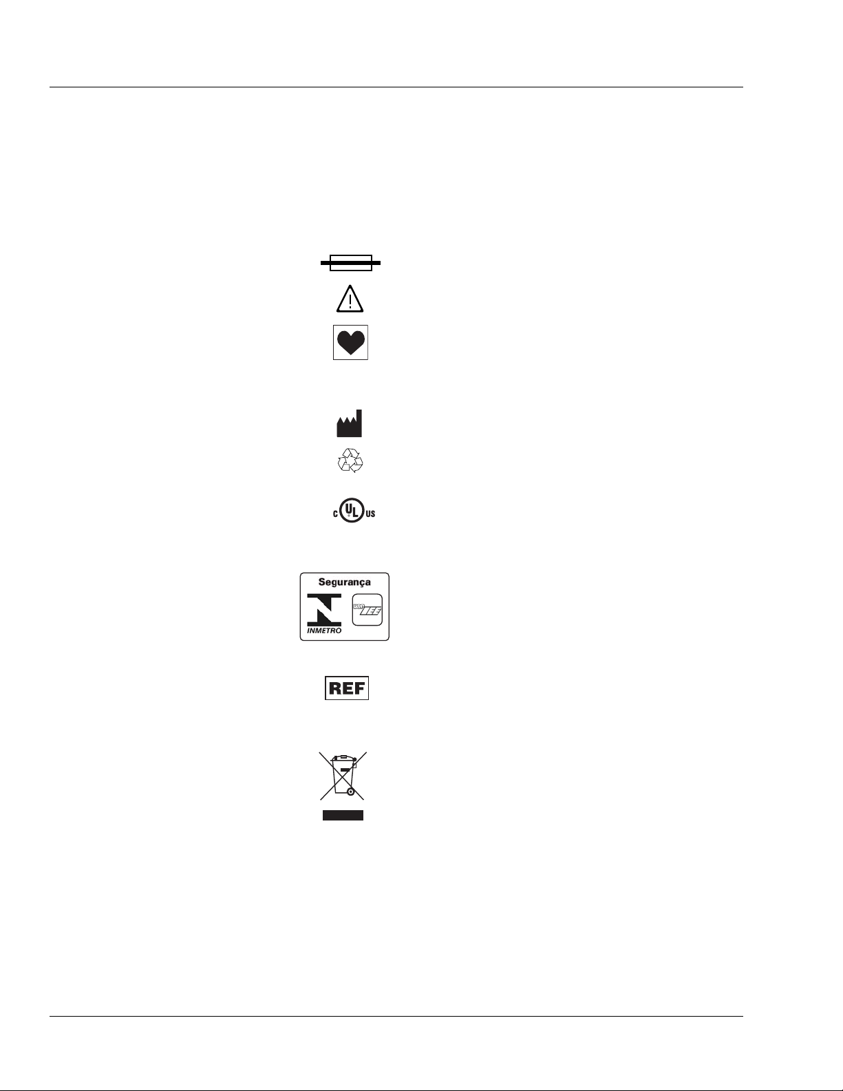
Labeling Symbol Definitions
Labeling symbol definitions (device and packaging):
IPX1 Drip-proof equipment: enclosed equipment protected
against dripping fluids in accordance with IEC 60529.
~
Alternating current or equipment intended to be connected
to an alternating current (AC) source.
Fuse.
Attention, consult accompanying documents.
Type CF equipment in accordance with UL 60601-1. The
Type CF Applied Part symbol indicates the level of electric
shock protection for the patient contacting parts such as the
IV set. UL/IEC/EN 60601-1 defines CF as providing
greater protection than Type B or Type BF.
Manufacturer.
Recyclable, dispose of properly.
S
I
F
S
I
A
E
L
D
C
5R78
MEDICAL EQUIPMENT
UL 60601-1
CAN/CSA C22.2 No. 601.1
OCP 0011
For products where this mark is present, the device is
classified by Underwriters Laboratories Inc. with respect to
electric shock, fire, and mechanical hazards only in
accordance with UL 60601-1 and CAN/CSA C22.2 No.
601.1.
Brazil certification to:
• INMETRO - National Institute of Metrology,
Standardization and Industrial Quality.
• USP-IEE - University of São Paulo Institute of
Electrotechnics and Energy.
Catalog number.
Serial number.
Symbol (WEEE 2002/96/EC)
For product disposal, ensure the following:
• Do not dispose of this product as unsorted municipal
waste.
• Collect this product separately.
• Use collection and return systems available to you.
Bar below bin: Product distributed after August 13, 2005.
For more information on return, recovery or recycling of
this product, please contact your local Baxter
representative.
1-4 COLLEAGUE CXE VOLUMETRIC INFUSION PUMP OPERATOR’S MANUAL 071960491
Page 17

Introduction Safety Summary
Pb
Nonspillable Battery
38°C
15°C
40°C
-15°C
57°C
-29°C
10
6
For product disposal, ensure the following:
• Do not dispose of this product as unsorted municipal
waste.
• Collect this product separately.
• Use collection and return systems available to you.
• Battery must be recycled.
Bar below bin: Product distributed after August 13, 2005.
Battery: Nonspillable lead acid sealed battery.
For more information on return, recovery or recycling of
this product, please contact your local Baxter
representative.
Fragile; handle with care.
Keep dry.
20%
50kPa
%
85%
106kPa
Operating temperature limits.
Storage temperature limits.
Transport temperature limits.
Transport humidity limits.
Transport atmospheric pressure limits.
Carton stacking limit (single channel pump).
Carton stacking limit (triple channel pump).
071960491 COLLEAGUE CXE VOLUMETRIC INFUSION PUMP OPERATOR’S MANUAL 1-5
Page 18

1 Warnings and Cautions
SN
15040362DL
Sequential
Number
Single Channel COLLEAGUE
CXE Pump
Year of Manufacture
(15 = 2005)
Month of
Manufacture
15060362UL
Sequential
Number
Triple Channel COLLEAGUE 3
CXE Pump
Year of Manufacture
(15 = 2005)
Month of
Manufacture
Labeling abbreviations:
COMM. PORT
VOL.
CONT.
Serial Number Format:
Communications Port
Vo l u m e
Contrast
SN
Warnings and Cautions
Definitions
Examples:
15061234UL manufactured June 2005
17122456DL manufactured December 2007
General Warnings and Cautions are included here. Additional Warnings
and Cautions appear throughout the manual.
Warning messages indicate a possible hazard which, if not avoided,
could result in severe personal injury or death.
Caution messages indicate a problem or unsafe practice which, if not
avoided, could result in minor or moderate personal injury, product or
property damage.
Note messages provide supplemental information to the accompanying
text.
1-6 COLLEAGUE CXE VOLUMETRIC INFUSION PUMP OPERATOR’S MANUAL 071960491
Page 19

Introduction Warnings and Cautions
!
WARNING
!
!
WARNING
!
!
WARNING
!
!
WARNING
!
!
WARNING
!
!
WARNING
!
!
WARNING
!
!
WARNING
!
Warnings
General Warnings:
The COLLEAGUE 3 CXE pump is intended for use in delivering multiple infusions
to a single patient. Never use the pump to deliver infusions to more than one
patient simultaneously.
Do not use this pump in Linear Accelerator Radiation Therapy suites or Magnetic
Resonance Imaging Suites.
The pump has not been evaluated for use in hyperbaric chambers. Use in these
areas may result in operation that is not within the constraints and parameters of
the device.
The pump has not been evaluated for compatibility with Extracorporeal Membrane
Oxygenation (ECMO) systems.
Epidural administration of drugs other than those indicated for epidural use could
result in serious injury to the patient.
• Epidural administration of anesthetics is limited to short term infusion (not to
• Epidural administration of analgesics is limited to use with indwelling
• To prevent infusion of drugs not indicated for epidural use, do not use
• Clearly distinguish pumps used for epidural drug delivery from pumps used
This device should be repaired only by Baxter authorized service personnel or
Baxter-trained hospital biomedical engineering personnel, using only Baxter
recommended parts. There are risks associated with using anything other than
Baxter recommended parts. Baxter will assume no responsibility for incidents
which may occur if the product was not repaired in accordance with procedures
authorized by Baxter.
Procedural Warnings:
If the pump has been dropped or appears to be damaged, it should be taken out of
service and inspected by Baxter-trained, qualified personnel only.
Clinicians are advised to verify the proper route of delivery and that the infusion
site is patent. When using this pump, periodic patient monitoring must be
performed to ensure that the infusion is proceeding as expected. The pump is
capable of developing positive fluid pressures to overcome widely varying
resistances to flow such as resistance imposed by small-gauge catheters, filters,
or intra-arterial infusions. Although the pump is designed to stop fluid flow when
an alarm occurs, it is neither designed nor intended to detect infiltrations and will
not alarm under infiltration conditions.
exceed 96 hours) with indwelling catheters specifically indicated for short
term anesthetic epidural drug delivery.
catheters specifically indicated for either short term or long term analgesic
epidural drug delivery.
administration sets incorporating injection sites during epidural delivery.
for other routes of administration.
071960491 COLLEAGUE CXE VOLUMETRIC INFUSION PUMP OPERATOR’S MANUAL 1-7
Page 20

1 Warnings and Cautions
!
WARNING
!
!
WARNING
!
!
WARNING
!
Use only Baxter standard administration sets equipped with keyed slide clamps
that are labeled as being COLLEAGUE pump compatible or denoted with an “s” in
the product code. If you have questions about administration set compatibility,
contact the Baxter Product Information Center at the number shown on the
administration set labeling. Using anything other than the recommended
administration sets with this pump will result in operation that is not within the
constraints and parameters of the device.
Severe injury or death may result from using sets other than those approved by
Baxter Healthcare Corporation for use with COLLEAGUE pumps. Always read and
follow the instructions in the Operator’s Manual and those accompanying the set
and source container.
Use only CONTINU-FLO standard administration sets equipped with keyed slide
clamps and labeled as COLLEAGUE pump compatible or denoted with an “s” in
the product code as the primary fluid line when administering a secondary
medication/solution. See “Recommended Administration Sets,” 4-15. Carefully
follow the directions on the primary and secondary administration set labels.
When using the secondary infusion feature ensure:
• the medication/solution in the secondary source container is
compatible with the medication/solution in the primary source
container.
• the secondary administration set is connected to the appropriate
injection site on the CONTINU-FLO administration set.
• the interruption of the primary infusion is clinically appropriate for
the duration of the secondary infusion.
• the infusion runs from a secondary source container and not from a
primary container.
Pulling or tugging on the administration set tubing between the pump channel
and the patient may cause false Air Detected alarms, which will cause the pump to
stop infusing. In order to reduce the potential for this situation to occur:
• First, select an appropriate length administration set.
• Before loading the set into the pump, position the keyed slide clamp
at an appropriate location along the tube segment to ensure that
there is adequate length of tubing between the patient and the pump
to reduce tugging on the set.
• Lastly, ensure there is sufficient slack in the tubing between the
distal end of the tubing channel and the patient to prevent tube
tugging during activities such as moving the patient from one bed to
another, or transportation of the patient from one facility location to
another.
In order to avoid false alarms, the pump should never be placed on the bed
alongside the patient.
1-8 COLLEAGUE CXE VOLUMETRIC INFUSION PUMP OPERATOR’S MANUAL 071960491
Page 21

Introduction Warnings and Cautions
!
WARNING
!
!
WARNING
!
!
WARNING
!
!
WARNING
!
!
WARNING
!
CAUTION
CAUTION
The pump may not detect an upstream occlusion if one or more of the following
conditions exist:
• All air removed from the source container
• Incomplete insertion of the spike into the source container
• Improper venting of a rigid (glass bottle) or semi-rigid (plastic)
container, including BURETROL sets
If using rigid non-vented containers, refer to the appropriate
administration set instructions to determine the correct venting
procedure.
• The air vent above the burette chamber is not open
To help prevent upstream occlusions that may not be detected by the pump:
• Do not use a source container that has had all air removed.
• When using a BURETROL set, do not invert BURETROL and squeeze
fluid into the primary container, which may wet out the vent filter and
obstruct airflow.
Do not allow fluid to enter the tubing channel or load wet tubing into the pump.
Contact your Baxter Service Center for assistance immediately if fluid enters the
tubing channel. The tubing channel should be cleaned as soon as possible by
Baxter-trained, qualified personnel to minimize potential difficulties caused by
fluid pooling and drying on the mechanism. Fluid in the tubing channel can also
cause false Air In Line alarms. See “Authorized Service Centers,” 10-2.
Cautions
There may be periods of no flow for flow rates less than or equal to 1mL/hr.
Do not enter a Volume to be infused greater than the amount of fluid available in
the container.
COLLEAGUE pumps do not support same-bag loading dose or bolus as it may
lead to an over-infusion, under-infusion, or interruption of therapy.
General Cautions:
In the U.S., use of device is restricted by Federal Law (USA) to sale or use by,
on the order of, or under the supervision of a physician or other licensed
healthcare professional.
Follow the cleaning schedule and methods defined under “Cleaning,” 7-1 to
ensure proper maintenance of the device.
071960491 COLLEAGUE CXE VOLUMETRIC INFUSION PUMP OPERATOR’S MANUAL 1-9
Page 22

1 Notes
Notes
Note: Baxter requests that parties acquiring this device:
• Promptly report the receipt of this device to the manufacturer;
• Report the device’s purchases, receipt in trade, return after
sale, loss, destruction, or retirement.
• If this is an initial purchase from the manufacturer, you may
return a signed copy of the packing list to the manufacturer in
order to comply with these requirements. Call
1-800-THE-PUMP or Baxter’s local sales office for additional
information.
Indications for Use
The COLLEAGUE CXE and COLLEAGUE 3 CXE Volumetric
Infusion Pumps are capable of delivering medications, solutions,
parenteral nutrition, lipids, blood and blood components.
The COLLEAGUE CXE and COLLEAGUE 3 CXE pumps are capable
of infusing from semi-rigid containers, rigid containers, flexible IV
bags, and vented syringes.
The COLLEAGUE CXE and COLLEAGUE 3 CXE pumps are
designed to deliver infusion therapies via clinically acceptable routes of
administration, including intravenous, intra-arterial, epidural, and
subcutaneous routes.
The COLLEAGUE CXE and COLLEAGUE 3 CXE pumps are intended
for use in a wide variety of patient care environments for adult,
pediatric, and neonatal patients. The COLLEAGUE CXE and
COLLEAGUE 3 CXE pumps facilitate the delivery of routine and
critical infusion therapies via continuous and intermittent delivery using
primary and secondary infusion modes.
1-10 COLLEAGUE CXE VOLUMETRIC INFUSION PUMP OPERATOR’S MANUAL 071960491
Page 23

Introduction Indications for Use
The COLLEAGUE CXE and COLLEAGUE 3 CXE pumps can be used
in the following care areas:
General Floor of the
Hospital
Critical/Intensive Care
Neonatal Intensive Care
Pediatric Care
Labor/Delivery/Postpartum
Hospice Facility
Outpatient/Subacute
Facilities
Nursing Facilities
Long Term Care/
Rehabilitation
Facilities
Operating Room/Anesthesia
Post Anesthesia/Recovery
Cardiac Catheterization Lab
Emergency Room
Ground Ambulance
Note: The COLLEAGUE CXE and COLLEAGUE 3 CXE pumps have
not been evaluated for use in care areas other than those listed
above.
Diagnostic Nuclear
Medicine
Oncology Floor
Burn Unit/Trauma
071960491 COLLEAGUE CXE VOLUMETRIC INFUSION PUMP OPERATOR’S MANUAL 1-11
Page 24

1 Indications for Use
1-12 COLLEAGUE CXE VOLUMETRIC INFUSION PUMP OPERATOR’S MANUAL 071960491
Page 25

Overview
Chapter 2
Chapter 2 Description
This chapter describes the controls, indicators, and displays on the
pump, and provides a brief functional description of the pump’s features
and infusion modes. The following information is provided in this
chapter:
“Description of Controls and Indicators” on page 2-2
“Display Reference Guide” on page 2-9
“Label Location” on page 2-16
“Pump Software Features” on page 2-18
“Infusion Modes” on page 2-19
071960491 COLLEAGUE CXE VOLUMETRIC INFUSION PUMP OPERATOR’S MANUAL 2-1
Page 26
2 Description of Controls and Indicators
.
E
C
X
E
X
C
C
O
L
L
E
A
G
U
E
G
U
A
R
D
I
A
N
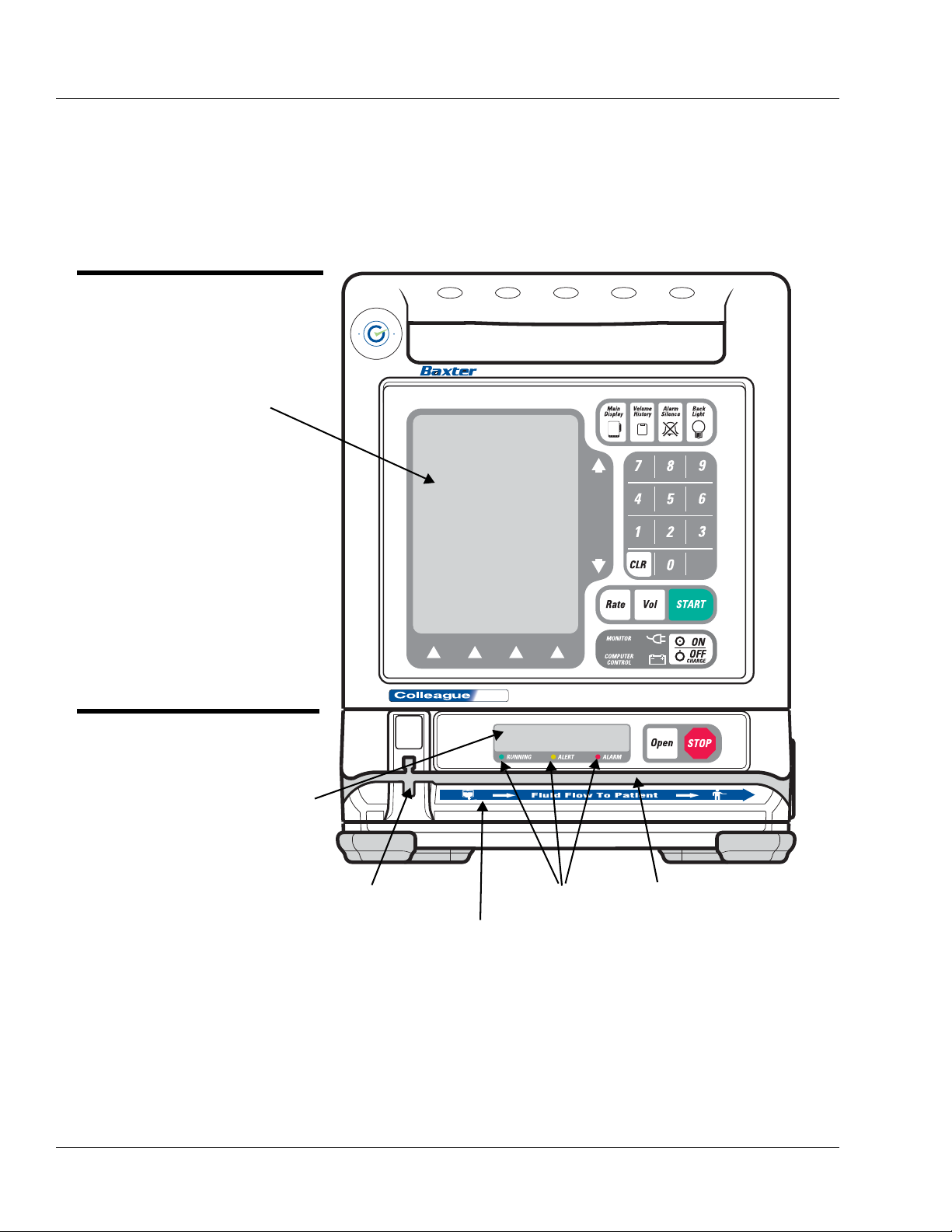
Figure 2-1 Front View, Single Channel Pump
MAIN BODY
See Table 2-1
PUMP MODULE
See Table 2-2
MAIN DISPLAY
PUMP MODULE DISPLAY
SLOT FOR KEYED SLIDE CLAMP STATUS LEDS TUBING CHANNEL
FLUID FLOW DIRECTION LABEL
Description of Controls and Indicators
Front Panel Features
Figure 2-1 is the front view of the single channel pump.
2-2 COLLEAGUE CXE VOLUMETRIC INFUSION PUMP OPERATOR’S MANUAL 071960491
Page 27
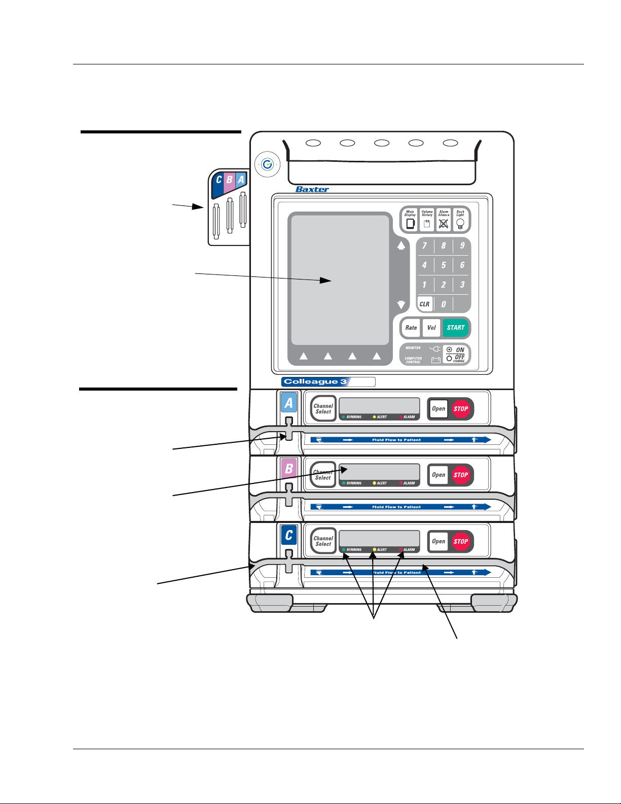
Figure 2-2 Front View, Triple Channel Pump
CHANNEL A
CHANNEL C
CHANNEL B
MAIN DISPLAY
MAIN BODY
See Table 2-1
PUMP MODULES
See Table 2-2
PUMP MODULE
DISPLAY
SLOT FOR KEYED
SLIDE CLAMP
STATUS LEDS
TUBING CHANNEL
TUBING CHANNEL
TUBING GUIDE
Description Description of Controls and Indicators
Figure 2-2 is the front view of the triple channel pump. Table 2-1
describes the controls and indicators on the main body of the pump.
A
E
G
L
U
L
E
O
C
G
N
U
A
A
I
R
D
.
E
X
C
C
X
E
071960491 COLLEAGUE CXE VOLUMETRIC INFUSION PUMP OPERATOR’S MANUAL 2-3
Page 28
2 Description of Controls and Indicators
Table 2-1 Main Body Controls and Indicators
Item Description
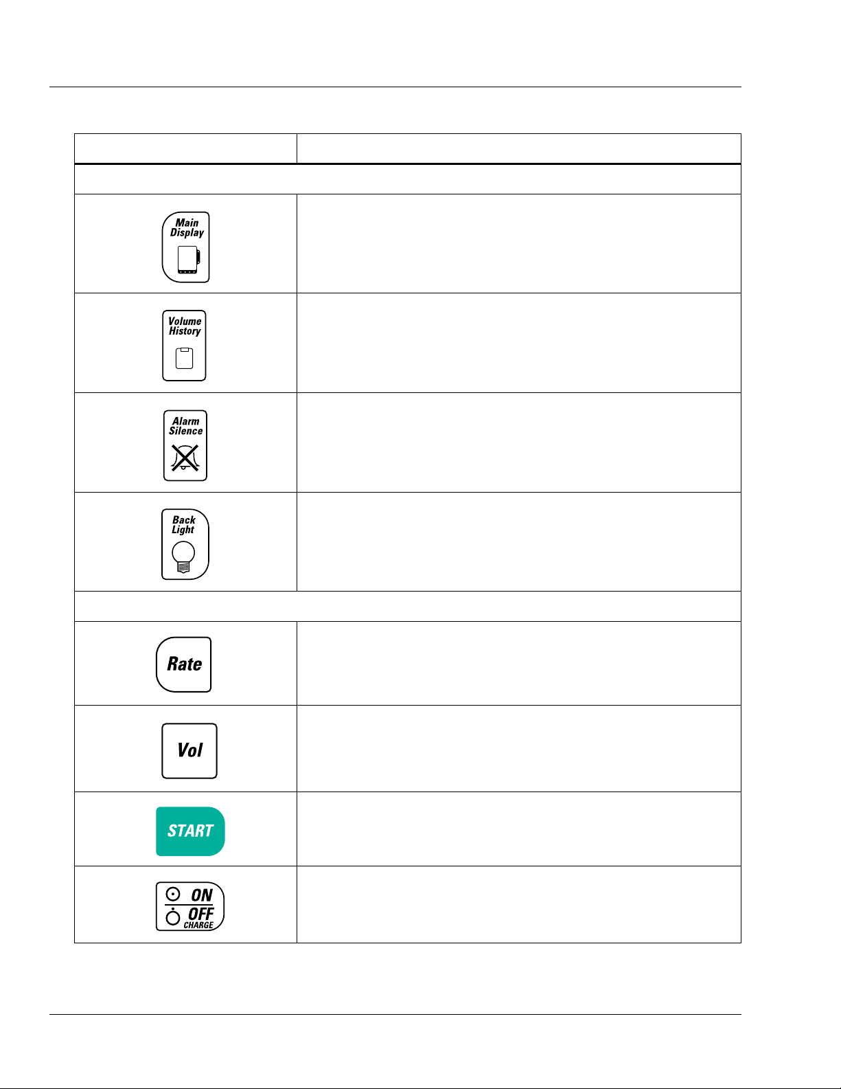
Function Keys
This key accesses the Main Display screen from all other operating screens,
except screens with pop-up windows or passcode service functions.
This key accesses the Volume History screen, allowing the user to view a
history of volume delivered. For triple channel pumps, the volume history
screen presents information for all three channels.
This key silences alarms and alerts for two minutes.
This key turns the back lights for the main display and the pump module
display(s) on and off. During battery-powered operation, this key illuminates
the back lights for 60 seconds following the last key press.
Action Keys
This key selects the Rate field.
This key selects the Vol (Volume to be infused) field.
This key initiates the infusion from any programming screen if all the
required programming values have been entered.
This key powers the pump on or off. If the pump is on, pressing this key once
causes the pump to display the Power Off pop-up, which requests
confirmation that the user intends to turn the pump off.
2-4 COLLEAGUE CXE VOLUMETRIC INFUSION PUMP OPERATOR’S MANUAL 071960491
Page 29
Description Description of Controls and Indicators
.
Table 2-1 Main Body Controls and Indicators — continued
Item Description
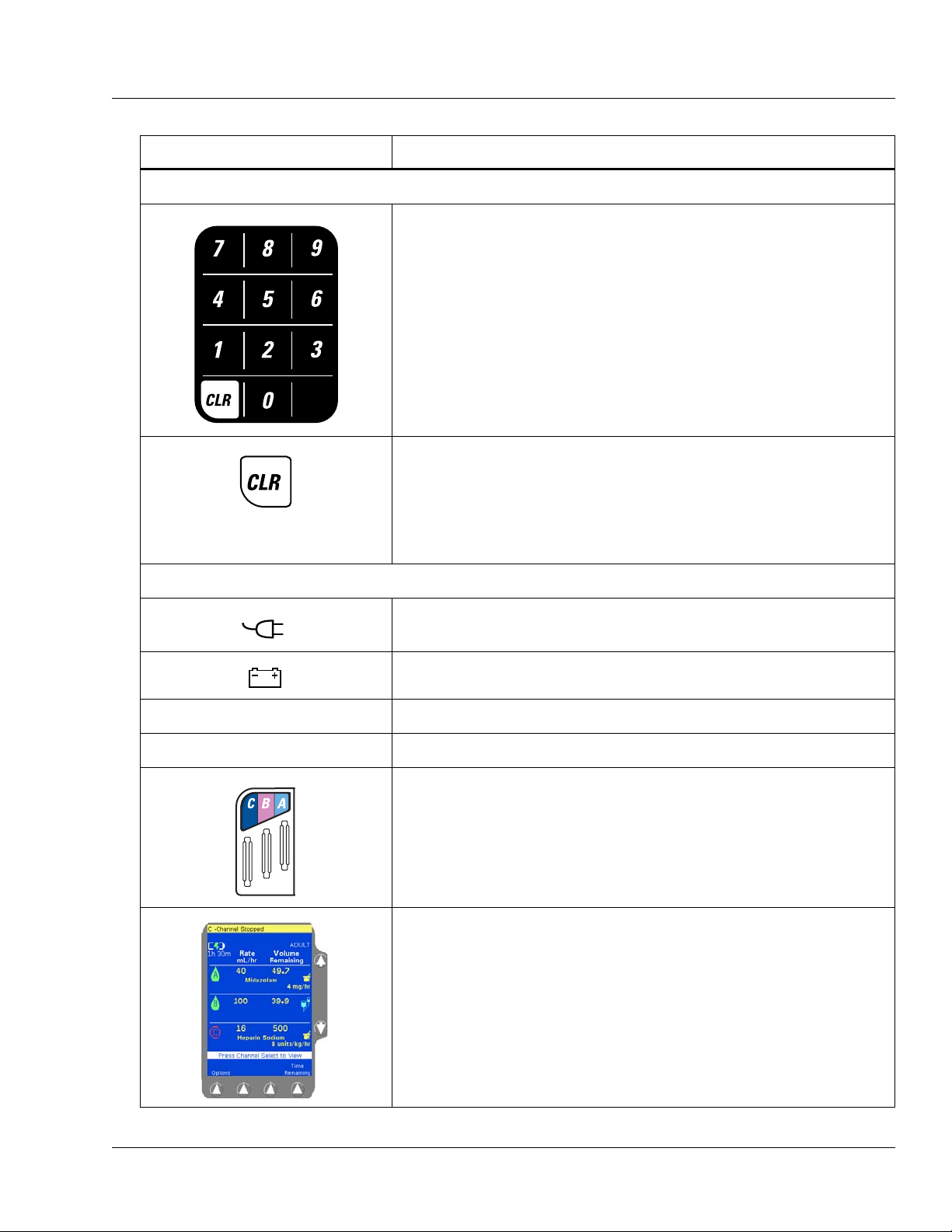
Numeric Keypad
The numeric keys and decimal point key are used to enter programming
values.
The CLR (Clear) key clears the values from the field highlighted on the
display. Pressing the key a second time restores the last value saved. If
multiple fields were cleared, the pump attempts to restore values whenever
possible.
The CLR key can also be used to clear a label if the label field is highlighted
and the infusion is stopped.
Icons
This green icon is lit whenever the pump is plugged into AC power.
Illumination of this icon also indicates the battery is being charged.
This yellow icon is lit only when the pump is operating on battery power.
MONITOR For Baxter diagnostic purposes only.
COMPUTER CONTROL FOR FUTURE USE.
Triple channel pumps only. The color-coded tubing guide on the left side of
triple channel pumps assists the clinician in identifying lines during a
multi-channel infusion. The tubing for each channel should be placed in the
corresponding tubing guide slot (A, B, C).
The pump’s Main Display is capable of displaying 10 different colors and
includes information for all three channels of a triple channel pump.
Note: For optimum viewability, view the display from a position
directly in front of the screen.
071960491 COLLEAGUE CXE VOLUMETRIC INFUSION PUMP OPERATOR’S MANUAL 2-5
Page 30
2 Description of Controls and Indicators
Pump Module Features
The Pump Module(s) are located below the Main Body. Triple channel
pumps have three pump modules. See Figure 2-1 and Figure 2-2 for
illustrations of the pump modules. The pump module controls and
indicators are described in Table 2-2.
.
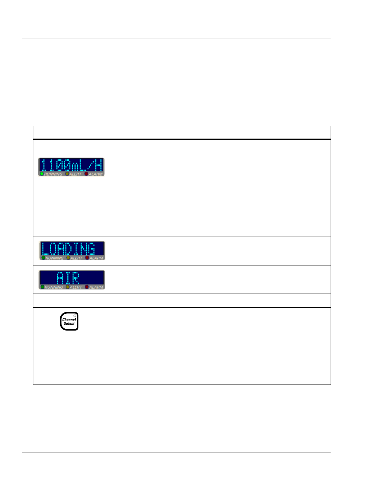
Table 2-2 Pump Module Controls and Indicators
Message Display
Key Description
Description
Pump Module Display
Note: If the pump is running on battery power, the pump module display is
blank to conserve battery power.
During infusions, the eight-character display on each channel shows one of the
following four message options:
•Rate
• Time Remaining
• Volume Infused
• Label
The message displayed depends upon the specific options selected by the care site.
Specific operations, such as tube loading, are also indicated on the pump module
display.
The pump module display also provides brief alarm and alert messages.
Triple channel pumps only.
• When pressed once, this key selects or deselects a particular pump channel for use.
The LED on the key lights and the selected channel’s programming screen appears
on the Main Display.
• Pressing this key when the channel is selected (LED is on), with no alerts or alarms
present and the channel stopped, opens the Standby pop-up for the selected channel,
allowing the user to place the channel in Standby.
• When the pump channel is in Standby, pressing this key takes the channel off
Standby and displays the channel’s programming screen.
2-6 COLLEAGUE CXE VOLUMETRIC INFUSION PUMP OPERATOR’S MANUAL 071960491
Page 31

Description Description of Controls and Indicators
Fluid Flow to Patient
Table 2-2 Pump Module Controls and Indicators — continued
• When there is no administration set in the pump, pressing this key opens the loading
mechanism so that the administration set can be loaded.
• When there is an administration set in the pump, pressing this key opens the loading
mechanism so that the administration set can be removed.
When the pump channel is running, pressing the STOP key for that channel stops the
infusion.
Fluid Flow Symbol Description
This fluid container symbol located below the left side of the tubing channel indicates
the upstream side of the pump. When loading the administration set, always ensure
that the tubing from the container enters the left side of the pump.
This patient symbol below the right side of the tubing channel indicates the
downstream side of the pump. When loading the administration set, always ensure that
the tubing from the pump to the patient exits right side of the pump.
These arrows indicate the direction of fluid flow while the pump is running.
LEDs Description
RUNNING LED
This green LED remains on continuously during an infusion.
ALERT LED
This yellow LED remains on continuously during an alert condition, if there are no
active alarms.
ALARM LED
This red LED flashes on and off during an alarm condition and remains on
continuously during a failure condition.
CHANNEL SELECT LED
Triple channel pumps only. This LED is lit when the associated pump channel is
selected.
071960491 COLLEAGUE CXE VOLUMETRIC INFUSION PUMP OPERATOR’S MANUAL 2-7
Page 32

2 Description of Controls and Indicators
MANUAL TUBE
RELEASE
(only one on single
channel pump)
MOUNTING
CLAMP KNOB
PANEL LOCKOUT
BUTTON
COMMUNICATION
PORT
MOUNTING CLAMP
RELEASE LATCH
MAIN DISPLAY
CONTRAST CONTROL
POWER CORD
NOTE: THE CORD
MAY DIFFER FROM
THAT SHOWN.
AUDIO SPEAKER
VOLUME CONTROL
FUSE HOLDERS
BACKUP BEEPER GRILL
AUDIO SPEAKER
GRILL
Rear Panel Features
See Figure 2-3 for the rear view of a triple channel pump. Table 2-3
describes the rear panel features.
Table 2-3 Rear Panel Features
Communication port An RS232 interface enables optional communication functions. For service use only.
Fuse holders The pump’s fuses are located inside.
Volume and Contrast
Controls
Figure 2-3 Rear View, Triple Channel Pump
Item Description
Thumbwheels for increasing and decreasing the audio volume and display contrast
settings.
2-8 COLLEAGUE CXE VOLUMETRIC INFUSION PUMP OPERATOR’S MANUAL 071960491
Page 33

Description Display Reference Guide
Table 2-3 Rear Panel Features — continued
Item Description
Audio speaker and beeper Generate alert and alarm tones.
Mounting clamp and knob Secures the pump to a pole.
Manual tube release Flip-out knob for manual tube unloading.
PANEL LOCKOUT button
The Panel Lockout button disables all the front panel keys except the Main
Display
Back Light
, Volume History, Channel Select (for triple channel pumps only), and
keys, and the Options, Primary, and Secondary soft keys for
viewing.
Color Reference Guide
Table 2-4 describes the meaning of the colors used on the device and
displays.
Table 2-4 Pump and Display Colors
Color Description
Yellow Yellow is used to call attention to a condition. Infusion program information is yellow. Yellow is
used in the display status line to indicate an alert condition. The ALERT LED on the pump head
module is yellow.
Red Red is used to indicate a serious condition or stop. Red is used in the display status line to indicate an
alarm or failure condition. The red stop sign icon indicates that an infusion is stopped. The ALARM
LED and the STOP key on the pump head module are red.
Green Green is used to indicate normal operation or start. The green drop icon indicates that an infusion is
running. The RUNNING LED on the pump head module and the START key on the pump are green.
White White is used for all basic information on the programming and main display screens, and as a
background color for the prompt line and some pop-ups. Also used for the Lock icon and the Flow
Check icon.
Dark blue Dark blue is used as the background color for all programming and main display screens.
Light blue Light blue is used for the secondary icon.
Black Black text is used on a yellow background to describe alert conditions.
Display Reference Guide
The Main Display provides two types of screens: the main display
screen and programming screens.
071960491 COLLEAGUE CXE VOLUMETRIC INFUSION PUMP OPERATOR’S MANUAL 2-9
Page 34

2 Display Reference Guide
Main Display Screen
The main display screen provides information about the current or most
recent infusion. Information which may appear on main display screens
is described in the following table. Examples of main display screens are
shown in and described in Table 2-5.
Table 2-5 Main Display Screen Areas
Area Function
Battery charge icon/status A battery charge icon with the estimated battery time displayed in hours and minutes.
Status line This highlighted area at the top of the display shows alert, alarm, and failure messages.
For triple channel pumps, it also identifies the channel to which these conditions apply
(A, B, or C). Alert messages appear against a yellow background and alarm or failure
messages appear against a red background.
PERSONALITY feature
set
Operating state icons Animated green drop: indicates infusion is running
Infusion parameters The programmed values for the current or most recent infusion, including rate, time
Dose mode identifier If the current infusion was programmed using a dose mode, the mode is displayed below
Prompt Line The single line of highlighted type just below the body provides prompts for user action.
Pop-up Window This message box is used to provide additional information that may or may not require
Label (Optional) A label identifying the current infusion, if configured and selected, is displayed just
The name of the currently selected PERSONALITY feature set is displayed near the top
left corner of the display.
Red stop sign: indicates infusion is stopped.
Light blue IV container: indicates that the current infusion is a secondary.
Yellow mortar and pestle: indicates that the current infusion is using a label for which
COLLEAGUE GUARDIAN feature limits have been configured.
Stopwatch: indicates a Delay Start infusion has been programmed.
remaining, and volume remaining.
the program values line.
user response.
below the infusion parameters. If the label has been configured with limits using the
COLLEAGUE GUARDIAN feature, then the mortar and pestle icon is also displayed
on the screen.
×Ø (Up and Down)
Arrow Keys
Soft Keys The four keys located below the display screen are referred to as soft keys.
Soft Key Identifiers Only the key identifiers applicable to the current activity are displayed above the soft
2-10 COLLEAGUE CXE VOLUMETRIC INFUSION PUMP OPERATOR’S MANUAL 071960491
These keys are used to select programming fields or to perform actions.
keys.
Page 35

Description Display Reference Guide
Infusion parameters
Label
Prompt line
PERSONALITY Feature Set
Operating State Icon
(Running)
Status line with
channel
identifier
Soft key identifiers
Soft keys
COLLEAGUE GUARDIAN
feature icon
(mortar and pestle)
Up and down arrow keys
Dose mode identifier
Triple Channel Pump
Single Channel Pump
Infusion parameters
Label
Prompt line
Battery Charge Icon
(blinking)
Operating State Icon
(Running)
Status line
(no message present)
Soft key identifiers
Soft keys
COLLEAGUE GUARDIAN
feature icon
(mortar and pestle)
Up and down arrow keys
Dose mode identifier
PERSONALITY Feature Set
Secondary infusion icon
Battery Charge Icon
(blinking)
Battery Charge Icon
(blinking)
Figure 2-4 Main Display Screen Information—Examples
071960491 COLLEAGUE CXE VOLUMETRIC INFUSION PUMP OPERATOR’S MANUAL 2-11
Page 36

2 Display Reference Guide
Figure 2-5 Programming Screen Information — Examples
Pop-up window
Rate Field
Volume Field
Status Line
Soft key identifiers
Prompt line
Soft keys
Triple Channel Pump
Single Channel Pump
Rate Field
Volume Field
Status Line
Soft key identifiers
Prompt line
Soft keys
Pop-up window
Secondary Infusion Icon
Battery Charge Icon
(blinking)
Battery Charge Icon
(blinking)
Secondary Infusion Icon
Programming Screens
Programming screens have fields where infusion program values are
entered. The programming screens for each programming mode are
different because each mode requires that different information be
programmed. Programming screen examples are shown in Figure 2-5.
2-12 COLLEAGUE CXE VOLUMETRIC INFUSION PUMP OPERATOR’S MANUAL 071960491
Page 37

Description Display Reference Guide
Figure 2-6 Menu Example
Pop-up Windows
Pop-up windows are message boxes that appear on top of the usual
screen display. Pop-ups may require user response in order to clear them
from the display.
Menus
In some situations, a menu containing additional selections is provided
(Figure 2-6). To select a menu item, use the
desired selection, then press the
Select soft key.
×Ø keys to highlight the
Main Display Icons
Table 2-6 Main Display Icons
Icon Description
Table 2-6 describes the icons that appear on the Main Display.
This icon indicates that air has been detected by the air sensor.
This icon indicates that air has exited from the air sensor area and fluid is now
detected.
The battery charge icon is displayed at all times in the upper left part of the screen.
The number of filled areas in the battery charge icon is an approximate indication of
the battery charge level. When the battery time remaining is 80 to 100%, the icon
contains three green bars as shown at left.
As the battery charge level decreases, the battery charge icon changes. When the
battery time remaining is 60 to 80%, the icon contains two green bars as shown at left.
071960491 COLLEAGUE CXE VOLUMETRIC INFUSION PUMP OPERATOR’S MANUAL 2-13
Page 38

2 Display Reference Guide
Table 2-6 Main Display Icons — continued
Icon Description
As the battery charge level continues to decrease, the battery charge icon continues to
change. When the battery time remaining is 20 to 60%, the icon contains two yellow
bars as shown at left.
When the battery time remaining is less than 20%, the battery charge icon contains
one red bar as shown at left.
When the battery time remaining is only 5 minutes, the battery charge icon appears as
an empty outline as shown at left. The icon will remain an empty outline until the
battery is depleted and pump shuts itself off.
If the pump’s batteries need replacement when the pump is first powered on, a
Damaged Battery! Service Now alarm occurs and this icon flashes on the
Power On screen. The pump cannot be used. Send the pump to service.
If the pump’s batteries need replacement during pump operation, a
Damaged Battery! Service Now alert occurs and this icon flashes instead of
the battery charge icon. Ensure the pump is plugged into AC power. Do not use the
pump for transport. Have the pump serviced as soon as possible so the batteries can be
replaced.
When the pump is plugged in, the battery charge icon alternates with the charging icon
shown at left.
When the pump is unplugged and operating on battery power, the battery charge icon
alternates with the Plug In icon shown at left, and the approximate battery operating
time is displayed below the icon. The pump should be plugged in whenever possible
to maintain battery charge.
A drop icon is displayed for each channel that is running, and beside the FLUID and
AIR icons when the pump is used to purge air from the tubing following an Air In
Line alarm.
The flow check icon indicates approximate level of downstream occlusion. The
greater the resistance to fluid flow, the greater the number of solid arrows displayed.
This icon indicates the screen is displaying secondary infusion information for a
channel.
This icon is displayed on the Programming screen when a pump channel is stopped.
This icon is displayed on the Main Display screen when a pump channel is stopped.
The appropriate channel letter is displayed inside of the stop symbol (A, B, or C).
When the keypad is locked, the Lock icon is displayed between the second and third
soft keys. The following keys remain available when the keypad is locked so that
infusion status information can be viewed: Main Display, Back Light, Volume
History, Primary, Secondary and Options.
2-14 COLLEAGUE CXE VOLUMETRIC INFUSION PUMP OPERATOR’S MANUAL 071960491
Page 39

Description Display Reference Guide
MORE
ARROW
Table 2-6 Main Display Icons — continued
Icon Description
This icon indicates a Delay Start infusion. It is displayed on the primary programming
screen when programming a delay start infusion for a channel, and on the main
display when a programmed delay start infusion is pending for a channel.
Mortar and pestle icon indicates that the programmed infusion is using a label for
which the COLLEAGUE GUARDIAN feature has been configured. Icon appears on
the programming screen when a COLLEAGUE GUARDIAN feature label has been
selected, and on the main display to the right of each channel running an infusion
utilizing a COLLEAGUE GUARDIAN label.
Yellow Triangle next to a label in the COLLEAGUE GUARDIAN label list indicates
that the label allows non-standard concentrations to be programmed by the clinician.
White triangle next to a field on the programming screen for a COLLEAGUE
GUARDIAN infusion indicates that the clinician has changed the default value.
Triangle next to the label while the infusion is running indicates that the clinician has
programmed the infusion using a non-standard concentration.
When a list contains more information than can be displayed on a single screen, an
arrow is displayed in the lower right and/or the upper right corner. Use the Page Up
and Page Down soft keys to page through the list.
071960491 COLLEAGUE CXE VOLUMETRIC INFUSION PUMP OPERATOR’S MANUAL 2-15
Page 40

2 Label Location
ATT ENTI ON
MANUAL TUBE RELEASE
MOUNTING CLAMP
SIGNATURE/RATINGS
PATENTS (ON UNDERSIDE)
MAINTAIN BATTERY CHARGE (OPTIONAL)
SERIAL NUMBER
BAR CODE
COLLEAGUE
GUARDIAN
FEATURE
CE MARK
WORDMARK
COLLEAGUE CXE
FLUID FLOW
VOLUME CONTROL
FUSES EXTERNAL
(English pumps only)
ACCESSORIES
POWER CORD
WARNING
CONTRAST CONTROL
UL/cUL/WEEE
SI G NATUR E/R AT INGS
(English, for non-English
pumps only)
SIGNATURE/RATINGS
(local language, for nonEnglish pumps only)
TEMPERATURE LIMITS
Label Location
The pump’s labels provide additional information about the pump.
Figure 2-7 shows the location of the pump’s labels for single channel
pumps. Figure 2-8 shows the location of the pump’s labels for triple
channel pumps. If any labels are missing or damaged, contact your local
Baxter Service Center for replacement information.
2-16 COLLEAGUE CXE VOLUMETRIC INFUSION PUMP OPERATOR’S MANUAL 071960491
Figure 2-7 Location of Pump Labeling, Single Channel Pump
Page 41

COLLEAGUE 3 CXE
CHANNEL
SELECT “A”
LABEL
TUBING GUIDE
LABEL
CHANNEL
SELECT “B”
LABEL
CHANNEL
SELECT “C”
LABEL
WORDMARK
FLUID FLOW
VOLUME CONTROL
FUSES EXTERNAL
ACCESSORIES
PATENTS (ON UNDERSIDE)
CONTRAST CONTROL
MANUAL TUBE RELEASE
ATT E NTIO N
SERIAL NUMBER
BAR CODE
CE MARK
SI G NATUR E/R AT INGS
(English pumps only)
MAINTAIN BATTERY CHARGE (OPTIONAL)
COLLEAGUE
GUARDIAN
FEATURE
POWER CORD
WARNING
UL/cUL/WEEE
SIGNATURE/RATINGS
(English, for nonEnglish pumps only)
SI G NATUR E/R AT INGS
(local language, for
non-English pumps
only)
TEMPERATURE LIMITS
Description Label Location
Figure 2-8 Location of Pump Labeling, Triple Channel Pump
071960491 COLLEAGUE CXE VOLUMETRIC INFUSION PUMP OPERATOR’S MANUAL 2-17
Page 42

2 Pump Software Features
Pump Software Features
In addition to basic infusion delivery capabilities, the pump has the
following features that help to enhance versatility and to help ensure
accurate infusion programming.
PERSONALITY Feature Sets
The pump provides the capability for a facility to create up to eight
different custom PERSONALITY feature sets, programmed with
infusion settings specific to a particular care area or therapy.
If PERSONALITY feature sets have been configured by the facility, the
clinician can select a different PERSONALITY feature set when the
pump is powered on. The PERSONALITY feature set can only be
changed at power on. For instructions on selecting a PERSONALITY
feature set, see “Selecting a Pump PERSONALITY Feature Set,” 4-5.
The Permanent Settings PERSONALITY feature set is the factory
default and its parameters cannot be changed, but it can be copied and
modified to create custom PERSONALITY feature sets tailored to the
needs of the facility. See “Configurable Options,” 6-1, for the default
settings.
PERSONALITY feature sets should be created only by
facility-authorized personnel, and the settings should be based upon
clinical protocols. An access code is required to program
PERSONALITY feature sets. See the COLLEAGUE Pump
Configuration Manual or the COLLEAGUE GUARDIAN
Configuration Tool documentation for more information.
2-18 COLLEAGUE CXE VOLUMETRIC INFUSION PUMP OPERATOR’S MANUAL 071960491
Page 43

Description Infusion Modes
Figure 2-9 Programming Screen
with Label
Figure 2-10 Main Display with
Label
Label Library
This configurable feature allows the user to select informational labels
for display on the Programming screen (Figure 2-9) and Main Display
screen (Figure 2-10), and an eight-character abbreviation of the label on
the Pump Module display. For information on selecting a label during
programming, see “Selecting a Label,” 4-23.
Labels are chosen from a list of predefined or custom labels. When the
Label Library feature is enabled, the user can select from the list of
available labels. For a list of predefined labels, see “Predefined Labels”
on page 6-7.
When the label library is viewed, the application labels are listed first,
followed by the medication/solution labels. For a list of application
labels, see “Application Labels,” 6-9.
Infusion Modes
071960491 COLLEAGUE CXE VOLUMETRIC INFUSION PUMP OPERATOR’S MANUAL 2-19
The infusion modes and programming functions available on the pump
depend on the facility-authorized configuration.
Page 44

2 Infusion Modes
Rate-Volume Infusions
This mode allows programming the flow rate and the infusion volume,
and the pump then runs at the programmed rate until the programmed
volume has been delivered. The pump then switches to the KVO (Keep
Vein Open) rate.
Rate-volume infusions can be programmed for primary or secondary
infusions. Secondary rate-volume infusions can be programmed without
stopping the primary infusion.
For instructions on programming rate-volume infusions, see
“Programming a Primary Rate-Volume Infusion,” 4-21 and
“Programming a Secondary Rate-Volume Infusion,” 4-46.
Volume-Time Infusions
This infusion mode lets the user enter the Volume to be Infused and
Time Duration, and the pump then calculates and displays the flow rate.
This feature is available in primary and secondary modes. Secondary
infusions can be programmed in Volume-Time without stopping the
primary infusion.
For instructions on programming Volume-Time infusions, see
“Programming a Primary Volume-Time Infusion,” 4-25 and
“Programming a Secondary Volume-Time Infusion,” 4-49.
COLLEAGUE GUARDIAN Feature
The COLLEAGUE GUARDIAN feature is a configurable option that
helps to reduce the potential for medication programming errors by
allowing program limits to be predefined for labels in the pump's label
library, including custom labels, based on facility or care area protocols.
The COLLEAGUE GUARDIAN feature allows the clinician to
compare pump programming with facility-defined dose guidelines at the
point of care. If the clinician programs values outside of the rule sets the
facility has programmed for a label, an out of limits warning occurs. The
COLLEAGUE GUARDIAN feature can be configured for rate-volume
and dose mode programming.
Note: All of the setup required to use the COLLEAGUE GUARDIAN
feature must be completed by facility-authorized personnel
according to the instructions in the COLLEAGUE Pump
Configuration Manual or the instructions accompanying the
COLLEAGUE GUARDIAN Configuration Tool.
2-20 COLLEAGUE CXE VOLUMETRIC INFUSION PUMP OPERATOR’S MANUAL 071960491
Page 45

Description Infusion Modes
Figure 2-11 COLLEAGUE
GUARDIAN Limits Warning Pop-up
Example
General information about the COLLEAGUE GUARDIAN feature is
listed below.
Labels configured with limits using the COLLEAGUE
GUARDIAN feature appear in a separate list. The list of
COLLEAGUE GUARDIAN labels is accessed by pressing the
Colleague Guardian soft key from the Primary Rate-Volume or
Volume-Time programming screen, or by pressing the
Mode
soft key and selecting Colleague Guardian from the
Programming Modes menu.
Labels selected from the COLLEAGUE GUARDIAN list have
predefined program limits. If the clinician chooses to change the
program so that the predefined limits are overridden, a warning is
displayed. The warning pop-up includes the programmed dose
and the preprogrammed dose limits. The clinician can choose to
cancel the dose and reprogram within the limits, or accept the
dose and override the limits. See Figure 2-11 for an example of
the Limits Warning pop-up.
Change
071960491 COLLEAGUE CXE VOLUMETRIC INFUSION PUMP OPERATOR’S MANUAL 2-21
Page 46

2 Infusion Modes
Figure 2-12 Infusion with
COLLEAGUE GUARDIAN Limit
Override
Figure 2-13 COLLEAGUE
GUARDIAN Programming Screen—
Example of Non-Standard
Weight-Based Dose
On the Main Display, the flow rate for infusions for which the
clinician chose to override the predefined limits are displayed in
red text on a yellow background. See Figure 2-12 for an example
of a Main Display screen for an infusion that overrides the
COLLEAGUE GUARDIAN feature limits. The triangle next to
the Midazolam label indicates that the standard concentration has
been edited from the predefined values.
Infusions utilizing the COLLEAGUE GUARDIAN feature are
identified on the pump’s information and programming screens
by the mortar and pestle icon to the right of the infusion
information. See Figure 2-12 and Figure 2-13 for examples.
The COLLEAGUE GUARDIAN feature can be used for primary
infusions only. A secondary infusion can be programmed to run
with a primary infusion that utilizes the COLLEAGUE
GUARDIAN feature.
COLLEAGUE GUARDIAN parameters can be set by authorized
facility personnel for labels in the pump’s label library, for any
primary dose mode and rate-volume infusions.
An optional default dose may be preconfigured; if so, the Dose
field is prefilled on the programming screen when the label is
selected.
For dose modes, COLLEAGUE GUARDIAN parameters can be
configured to allow changes to the standard concentration.
• If changes to standard concentration are not allowed, the
Diluent Volume and Concentration fields cannot be
edited by the clinician when programming an infusion.
• If changes to standard concentration are allowed, the
Diluent Volume and Concentration fields can be edited
by the clinician when programming an infusion. White
triangles appear beside the field names for fields that have
been edited. In the example shown in Figure 2-13, the
clinician has changed the Drug Amount and Diluent
Volume fields to values that differ from the programmed
COLLEAGUE GUARDIAN feature limits for Heparin
Sodium. The yellow triangle beside the Heparin Sodium
label indicates that the concentration can be edited.
For instructions on programming infusions using the COLLEAGUE
GUARDIAN feature, see “Programming a Primary COLLEAGUE
GUARDIAN Infusion (Non-Weight-Based),” 4-29 and “Programming a
Primary COLLEAGUE GUARDIAN Infusion (Weight-Based),” 4-32.
2-22 COLLEAGUE CXE VOLUMETRIC INFUSION PUMP OPERATOR’S MANUAL 071960491
Page 47

Description Infusion Modes
Rate
Dose
Concentration
----------------------------------=
Dose Modes
Dose programming lets the user program a primary infusion using dose
parameters. The dose can be programmed independent of patient
parameters or based on patient body weight. The following dose modes
are allowed:
General (independent of patient parameters)
• mg/hr
• mEq/hr
• mg/min
• mcg/hr
• units/hr
• mcg/min
Based on patient body weight
• mg/kg/hr
• mEq/kg/hr
• mg/kg/min
• mcg/kg/hr
• units/kg/hr
• mcg/kg/min
How Concentration is Determined
Concentration is a required infusion parameter. Concentration is
determined by dividing the drug amount into the diluent volume. If the
concentration is known, it can be entered directly into the pump. If
concentration is the first parameter entered, the Drug Amount and
Diluent Volume fields are cleared.
How Doses and Rates are Calculated
Concentration must be entered or calculated before the rate or dose can
be calculated. After the dose is entered, the pump calculates and displays
the rate. Similarly, after the rate is entered, the pump calculates and
displays the dose.
Conversion factors are applied as appropriate to calculate rate or dose
(i.e., 60 minutes = 1 hour, 1000 mcg = 1 mg, etc.).
To calculate rate from an entered dose, the following formulas are
applied:
General:
071960491 COLLEAGUE CXE VOLUMETRIC INFUSION PUMP OPERATOR’S MANUAL 2-23
Page 48

2 Infusion Modes
Rate
Dose Patient Weight×
Concentration
------------------------------------------------------=
Dose Rate Concentration×=
Dose
Rate Concentration×
Patient Weight
---------------------------------------------------=
Rate
Volume to be Infused
Time of Infusion
----------------------------------------------------=
Based on patient body weight:
To calculate dose from an entered rate, the following formulas are
applied:
General:
Based on patient body weight:
To calculate rate from an entered volume to be infused and entered time
of infusion, the following formula is applied:
Changing a Parameter After All Parameters Have Been
Entered
If all parameters have been entered and calculated and one of the
parameters is changed, one or more of the following occurs:
If the actual Dose is changed, the Rate is automatically
recalculated, or vice versa.
If the Drug Amount or Diluent Volume is changed, the
Concentration is recalculated.
If the Concentration is changed, the Drug Amount and Diluent
Volume will be cleared.
If a parameter that could indirectly affect the Dose or Rate (such
as patient weight) is changed, the Rate will change but the Dose
remains constant.
Changing Units of Measure
Units of measure can be changed for the Drug Amount and
Concentration values. Whenever a unit of measure is changed, the pump
automatically clears the program values of any parameters associated
with the changed units.
For instructions on programming dose infusions, see “Programming a
Primary Dose Mode Infusion (Non-Weight Based),” 4-36 and
“Programming a Primary Dose Mode Infusion (Weight-Based),” 4-40.
2-24 COLLEAGUE CXE VOLUMETRIC INFUSION PUMP OPERATOR’S MANUAL 071960491
Page 49

Description Infusion Modes
Figure 2-14 Primary Delay Start
Infusion Pending
Primary Delay Start Mode
Primary Delay Start is an optional feature available on the Programming
Modes menu. If Primary Delay Start does not appear on the
Programming Modes menu, this feature has not been enabled. Delay
Start lets the user program a primary rate-volume infusion to begin at a
specified time, in 24-hour format. A Delay Start infusion starts
automatically when the pump’s clock reaches the programmed Start At
time. If the pump is displaying a programming screen when the Delay
Start infusion begins, the display changes to the Main Display.
When a Delay Start infusion has been programmed, a wristwatch icon is
displayed on the Main Display screen (Figure 2-14) until it is time for
the infusion to begin.
When a Delay Start infusion begins, the pump channel’s infusion mode
changes to primary rate-volume and the main display shows the
programmed infusion information. The wristwatch icon changes to the
stop icon or the drop icon, depending upon whether the infusion is
stopped or running.
The
Secondary soft key for the channel is not available until the Delay
Start infusion starts running.
For instructions on programming Delay Start infusions, see
“Programming a Delay Start Infusion,” 4-54.
071960491 COLLEAGUE CXE VOLUMETRIC INFUSION PUMP OPERATOR’S MANUAL 2-25
Page 50

2 Infusion Modes
2-26 COLLEAGUE CXE VOLUMETRIC INFUSION PUMP OPERATOR’S MANUAL 071960491
Page 51

Environmental Conditions
!
WARNING
!
The pump should be operated within the following environmental
conditions in order to meet the pump's performance specifications:
Chapter 3
Chapter 3 Preparation for Use
Temperature: 15ºC to 38ºC (59ºF to 100ºF)
Relative Humidity: 20% to 95% (non-condensing)
Barometric Pressure: 70 to 106 kPa
Setup Instructions
Initial Installation
Do not use this pump in Linear Accelerator Radiation Therapy suites or Magnetic
Resonance Imaging Suites.
To ensure safe and proper operation, read the manual and any
instructions accompanying disposables or accessories before operating
this device.
To charge a new pump’s batteries:
1. Plug the power cord into a 100-120 VAC 50/60 Hz or 220-240 VAC
50/60 Hz outlet
2. Confirm that the plug icon is lit. This indicates that the batteries are
charging.
071960491 COLLEAGUE CXE VOLUMETRIC INFUSION PUMP OPERATOR’S MANUAL 3-1
Page 52

3 Setup Instructions
CAUTION
Figure 3-1 Pole Mount
Figure 3-2 Headboard (horizontal)
Mount
3. Before initially powering on the pump, charge the battery for at least
12 uninterrupted hours. A complete charge may take longer than
12 hours.
Mounting the Pump on an IV Pole
When attaching this pump to an IV pole, ensure it has been securely clamped
and ensure that the IV pole is stable and secure. Ensure that the pole is able to
support the pump, along with any other devices, without tipping or falling.
When attached to an IV pole, the pump may become unstable (tip and fall) if the
center of the mounting clamp knob (Figure 3-1) measures 96 cm (37.8 inches)
or higher from the floor. The pole diameter should be between 0.96 and 3.81 cm
(3/8 inch and 1-1/2 inches).
Note: To help loosen the mounting clamp knob, flip open and use the
two wing-shaped extensions on the knob.
1. For triple channel pumps: proceed to Step 2.
For single channel pumps: check to see if the clamp bracket is
positioned for mounting on a pole as in Figure 3-1. If so, continue
with Step 2; otherwise, see “Changing the Mounting Bracket
Orientation (Single Channel Pumps Only),” 3-3.
2. Attach mounting clamp by positioning the hinged clamp arm around
the IV pole.
3. Turn the mounting clamp knob clockwise to close the clamp arm.
Tighten until secure.
Mounting the Pump on a Headboard (Single Channel Pumps Only)
Note: To help loosen the mounting clamp knob, flip open and use the
two wing-shaped extensions on the knob.
1. Check to see if the clamp bracket is positioned for headboard
mounting or other horizontal applications as in Figure 3-2. If so,
continue with Step 2; otherwise, see “Changing the Mounting
Bracket Orientation (Single Channel Pumps Only),” 3-3.
2. Attach mounting clamp by positioning the hinged clamp arm over
the chosen fixture.
3. Turn the mounting clamp knob clockwise to close the clamp arm.
Tighten until secure.
3-2 COLLEAGUE CXE VOLUMETRIC INFUSION PUMP OPERATOR’S MANUAL 071960491
Page 53

Preparation for Use Check-out
A
B
C
D
Figure 3-3 Changing the
Mounting Bracket Orientation
!
WARNING
!
Changing the Mounting Bracket Orientation (Single Channel Pumps Only)
The instructions and Figure 3-3 illustrate how to change the orientation
from a pole mount (vertical) to a headboard (horizontal) mount. The
procedure for changing from a horizontal mount to a vertical mount is
similar, except that the positions of the clamp and plate cover are the
reverse of what is shown in the figures.
1. Press down and hold the latch (A in Figure 3-3) to release the
mounting clamp from the plate.
2. Grasp the mounting clamp knob and slide the clamp off of the
bracket (B in Figure 3-3).
3. Rotate the clamp counter-clockwise 90° (C in Figure 3-3) until the
open end of the clamp is towards the floor (see clamp in Figure 3-2).
4. Slide the clamp up onto the plate until you hear the clamp lock into
place (D in Figure 3-3). The clamp should now be positioned as in
Figure 3-2.
Check-out
5. Continue with attaching the clamp according to the applicable
mounting procedure above.
If the pump has been dropped or appears to be damaged, it should be taken out of
service and inspected by Baxter-trained, qualified personnel only.
Perform the following visual inspections before each use:
Display screens and keypads: check for wear, scratches, or cracks
Pump body: check for cracks and dents
Power cord and plug: check the cord and connectors for cracks
and damage. Do not use the pump if the connectors appear
damaged.
071960491 COLLEAGUE CXE VOLUMETRIC INFUSION PUMP OPERATOR’S MANUAL 3-3
Labels: check for scratches, cuts, and peeling, or fading, missing,
and obliterated labels and words.
If there is any evidence of damage, contact your authorized service
provider.
Page 54

3 Check-out
3-4 COLLEAGUE CXE VOLUMETRIC INFUSION PUMP OPERATOR’S MANUAL 071960491
Page 55

Starting Up
Chapter 4
Chapter 4 Operating Instructions
Note: Throughout the Operating Instructions chapters, sample screens
for a triple channel pump are shown. See “Display Reference
Guide” on page 2-9 for the screen display differences between
triple channel pumps and single channel pumps.
Powering On Using AC Power
Note:
Pump Status
Note:
Battery Power
Note:
Manual Tube
Release
The power cord must be connected to a 100-120 VAC 50/60 Hz or
220-240 VAC 50/60 Hz, properly grounded 3-wire receptacle.
Grounding reliability can only be achieved when the pump is connected
to an earth-grounded hospital grade receptacle. (When grounding
reliability is in doubt, the pump should be powered by its battery.) The
If the pump status is unclear, close any pop-up windows on the display and press the Main Display key to
continue.
If the pump is operating on battery power at start up,
refer to “Powering On Using Battery Power” on page
4-6.
The pump will not turn on if the Manual Tube Release
is in the open position.
071960491 COLLEAGUE CXE VOLUMETRIC INFUSION PUMP OPERATOR’S MANUAL 4-1
Page 56

4 Powering On Using AC Power
Figure 4-1 Pump Module Display
power cord must be disconnected from the power outlet (supply
receptacle) in order to disconnect the pump from AC power (mains
supply).
Self-diagnostic testing occurs whenever the pump is powered ON. If any
of the following occur during self-diagnostic testing, the pump must be
removed from service and inspected by Baxter-trained, qualified
personnel:
Dark spots or lines on Main Display while display is all white.
Light spots or lines on Main Display while display is all dark.
Portions of pump module displays do not light.
LEDs or the plug icon are not lit, or the battery icon is lit.
A series of three beeps, with two different tones, is not heard
during self-diagnostic test.
Audible speaker is not heard during speaker test.
Damaged Battery icon is displayed on power-on screens. If a
Damaged Battery! Service Now alarm occurs during power
on, the pump cannot be used. See “About the Damaged Battery
Alarm,” 8-8.
1. With the pump plugged in, press the ON/OFF CHARGE key.
Self-diagnostic tests begin.
a. The Main Display and pump module displays turn on.
b. The entire Main Display becomes light.
c. The entire Main Display becomes dark.
d. All 8 digits of all three pump module displays light fully,
then display
CLOSED (Figure 4-1), then turn off
completely.
e. All the LEDs and icons light briefly. The plug icon lights
and remains lit.
4-2 COLLEAGUE CXE VOLUMETRIC INFUSION PUMP OPERATOR’S MANUAL 071960491
Page 57

Operating Instructions Powering On Using AC Power
Figure 4-2 Speaker Test Screen
Figure 4-3 Speaker Test Failure
2. If the pump is running on AC power, the Main Display prompts the
user to perform the speaker test. This helps ensure that alarms and
alerts are audible and that the volume level is appropriate for the care
area. If the speaker test is not initiated within 10 minutes, the pump
turns itself off automatically.
Press and hold the
Speaker Test soft key to begin the audible
speaker test. The pump produces sound for as long as the key is
pressed. The volume control on the pump handle can be adjusted if
necessary to hear the speaker. The key must be held down until
No soft keys are displayed (Figure 4-2).
and
3. Do one of the following:
3.1 If the continuous tone is heard, press the Yes soft key. The
pump completes its self-test and then displays the Power
On Screen After Self-Test (Figure 4-4).
3.2 If the continuous tone is not heard, even after adjusting the
volume control, press the
No soft key. The pump displays a
pop-up to confirm whether the continuous tone is heard.
Press the
No soft key again to confirm that no tone is heard.
The pump displays the speaker failure message shown in
Figure 4-3. If this occurs, do not use the pump. Turn the
pump off and have it repaired as described in
“Troubleshooting Failures,” 8-2.
Yes
If the continuous tone is not heard during the speaker test,
alarms and alerts may not be audible during operation. Do
not use the pump. Send the pump to service.
071960491 COLLEAGUE CXE VOLUMETRIC INFUSION PUMP OPERATOR’S MANUAL 4-3
Page 58

4 Powering On Using AC Power
Figure 4-4 Power On Screen After
Self-Test
Figure 4-5 Main Display After
Self-Test
4. On completion of all self-diagnostic tests, the Power On screen
changes to the display shown in Figure 4-4 (for triple channel
pumps, Channels B and C power off after self-diagnostic tests
complete). The soft keys available on this screen depend on the
configuration options selected for the pump:
To clear all programming memory and volume history, press the
New Patient soft key.
Pressing the Change Personality soft key changes the display to
the Pump PERSONALITY feature set selection screen where
available preconfigured pump parameters can be selected.
Changing the PERSONALITY feature set also clears the volume
history and the programming parameter settings such as Rate and
Volume to be Infused.
See “Selecting a Pump PERSONALITY Feature Set,” 4-5 for
additional information.
If no keys are pressed, the pump will automatically display the Main
Display screen after approximately 10 seconds.
4-4 COLLEAGUE CXE VOLUMETRIC INFUSION PUMP OPERATOR’S MANUAL 071960491
Page 59

Operating Instructions Selecting a Pump PERSONALITY Feature Set
Figure 4-6 Example of Custom
PERSONALITY Feature Sets
Figure 4-7 Configuration Screen
Example
Selecting a Pump PERSONALITY Feature Set
The PERSONALITY feature set can only be changed at power on.
Changing the PERSONALITY feature set also clears the volume history
and the programming parameter settings such as Rate and Volume to be
Infused.
To change the PERSONALITY feature set:
1. Press the Change Personality soft key from the Power On Screen
after Self Test (Figure 4-4). A list of available PERSONALITY
feature sets is displayed.
2. Use the ×Ø keys to highlight the desired PERSONALITY
(Figure 4-6).
3. Press the Select soft key.
Viewing PERSONALITY Feature Settings at Power-Up
To view the settings for all the parameters of a PERSONALITY feature
set:
1. Turn the pump on, then press the Change Personality soft key. Use
×Ø keys to highlight the desired PERSONALITY feature set,
the
then press the
menu for the selected PERSONALITY feature set (Figure 4-7).
2. Use the ×Ø keys to highlight the desired configuration item. Press
Select soft key to view the details for the selected configuration
the
setting.
View Personality soft key to view the Configuration
feature set
071960491 COLLEAGUE CXE VOLUMETRIC INFUSION PUMP OPERATOR’S MANUAL 4-5
3. Press Done to exit.
Page 60

4 Adjusting the Audible Volume
Figure 4-8 Plug in Now Pop-up
Adjusting the Audible Volume
To adjust the volume of the audible tones produced by the pump:
1. Locate the volume control on rear of the device handle.
2. Rotate the volume control to increase or decrease the volume as
needed.
Adjusting the Display Contrast
To adjust the contrast of the pump’s main display:
1. Locate the contrast control on rear of the device handle.
2. Rotate the contrast control to increase or decrease the contrast as
needed.
Powering On Using Battery Power
Full/Partial Battery Charge
If the pump is powered up on battery power, a Plug In Now pop-up is
displayed (Figure 4-8) prior to the speaker test, showing the approximate
battery time remaining and prompting the user to plug the pump into an
AC power outlet.
To continue on battery power, press the Ok soft key. See
“Operating on Battery Power,” 4-8 for more information.
To continue on AC power, plug the pump into an AC outlet.
The Main Display then prompts the user to perform the speaker test.
Proceed to step 2 on page 4-3.
4-6 COLLEAGUE CXE VOLUMETRIC INFUSION PUMP OPERATOR’S MANUAL 071960491
Page 61

Operating Instructions Powering On Using Battery Power
Figure 4-9 Plug in Now Alert
Pop-up, Low Battery Condition
Figure 4-10 Plug in Now Alarm
Pop-up, Depleted Battery Condition
Low Battery Condition
If the pump is powered up on battery power and a Low Battery condition
exists, a Plug In Now alert pop-up is displayed (Figure 4-9) prior to the
speaker test, alerting the user that there is less than 30 minutes of battery
time remaining. Using battery mode is NOT recommended when this
alert occurs.
To continue on battery power, press the Ok soft key. See
“Operating on Battery Power,” 4-8 for more information.
To continue on AC power, plug the pump into an AC outlet.
The Main Display then prompts the user to perform the speaker test.
Proceed to step 2 on page 4-3.
Depleted Battery Condition
If the pump is powered up on battery power and a Depleted Battery
condition exists, a Plug In Now alarm pop-up is displayed prior to the
speaker test, alerting the user that battery damage will occur if the pump
is not plugged in, and the pump will shut down in less than 10 seconds
(Figure 4-10).
To continue on AC power, plug the pump into an AC outlet. A pop-up is
displayed alerting the user that the pump is charging and must be
allowed to sufficiently recharge the battery before operating on battery
power. Press the
Ok soft key. The Main Display then prompts the user to
perform the speaker test. Proceed to step 2 on page 4-3.
071960491 COLLEAGUE CXE VOLUMETRIC INFUSION PUMP OPERATOR’S MANUAL 4-7
Page 62

4 Battery Charge Icon Descriptions
Figure 4-11 Battery Charge Icon on
Main Display
Operating on Battery Power
The pump can be battery-powered in emergency situations and while
transporting patients. AC power should be used when not transporting
patients.
The battery charge icon is displayed at all times in the upper left part of
the screen, even when the device is operating on AC power (Figure
4-11). When the pump is unplugged and operating on battery power, the
battery charge icon alternates with the Plug In icon, and the approximate
battery operating time is displayed below the icon.
Charge the battery for at least 12 uninterrupted hours or until the battery
operating time displayed under the battery charge icon in the upper left
part of the screen is 3h 15m (for triple channel pumps) or 4h 00m (for
single channel pumps). A complete charge may take longer than
12 hours.
Battery time remaining adjusts based on flow rate; the batteries will
discharge at a faster rate at higher infusion rates. If the flow rate is
changed during an infusion, the battery time remaining will change
accordingly.
Battery Charge Icon Descriptions
See Table 4-1 for a list of battery charge icons and their meaning.
Battery time remaining is approximate.
Table 4-1 Battery Charge Icons and Descriptions
Icon Description
The battery charge icon is displayed at all times in the upper left part of the
screen. The number of filled areas in the battery charge icon is an
approximate indication of the battery charge level. When the battery time
remaining is 80 to 100%, the icon contains three green bars as shown at left.
As the battery charge level decreases, the battery charge icon changes. When
the battery time remaining is 60 to 80%, the icon contains two green bars as
shown at left.
As the battery charge level continues to decrease, the battery charge icon
continues to change. When the battery time remaining is at 20 to 60%, the
icon contains two yellow bars as shown at left.
When the battery time remaining is less than 20%, the battery charge icon
contains one red bar as shown at left.
4-8 COLLEAGUE CXE VOLUMETRIC INFUSION PUMP OPERATOR’S MANUAL 071960491
Page 63

Operating Instructions Battery Charge Icon Descriptions
CAUTION
Table 4-1 Battery Charge Icons and Descriptions
Icon Description
When the battery time remaining is only 5 minutes, the battery charge icon
appears as an empty outline as shown at left. The icon will remain an empty
outline until the battery is depleted and pump shuts itself off.
If the pump’s batteries need replacement when the pump is first powered on,
a
Damaged Battery! Service Now alarm occurs and this icon flashes
on the Power On screen. The pump cannot be used. Send the pump to
service.
If the pump’s batteries need replacement during pump operation, a
Damaged Battery! Service Now alert occurs and this icon flashes
instead of the battery charge icon. Ensure the pump is plugged into AC
power. Do not use the pump for transport. Have the pump serviced as soon
as possible so the batteries can be replaced.
When the pump is plugged in, the battery charge icon alternates with the
charging icon shown at left.
When the pump is unplugged and operating on battery power, the battery
charge icon alternates with the Plug In icon shown at left, and the
approximate battery operating time is displayed below the icon. The pump
should be plugged in whenever possible to maintain battery charge.
The batteries begin to recharge whenever the pump is plugged into AC
power. If there is less than 30 minutes of battery time remaining when
recharge begins, the pump will display the empty outline battery charge
icon until 30 minutes of battery time is achieved. The pump
will then display the battery charge icon with one red bar up
until the point when the maximum charge is achieved, at which time the
battery charge icon will display three green bars . The time
remaining on battery will continue to display the time remaining when
the pump was plugged in until the maximum charge is achieved.
If there is more than 30 minutes of battery time remaining when the
recharge begins, the pump will continue to display the battery charge
icon that was present when the recharge began up until the point when
the maximum charge is achieved, at which time the battery charge icon
will display three green bars . The time remaining on battery
will continue to display the time remaining when the pump was plugged
in until the maximum charge is achieved.
When charging the batteries, ensure the room temperature is between 15° C
(59° F) to 30° C (86° F) to minimize charge time and maximize battery life.
071960491 COLLEAGUE CXE VOLUMETRIC INFUSION PUMP OPERATOR’S MANUAL 4-9
Page 64

4 Battery Charge Alerts and Alarms
Figure 4-12 Running on Battery
Alert Pop-up
Figure 4-13 Limited Battery Alert
Pop-up
Battery Charge Alerts and Alarms
As the pump runs on battery and remaining battery time decreases, a
progression of alerts and alarms advise the user of the declining battery
power. These alerts and alarms are described below.
For additional information, see “Troubleshooting,” 8-1.
When the pump first begins to run on battery power, the Running on
Battery - Plug In Now alert occurs. An audible tone sounds and a Plug
In Now pop-up window displays (Figure 4-12), alerting the user that the
pump is operating on battery power and showing the approximate
battery time remaining. The pop-up will reappear every hour, counting
down the battery time until the battery time remaining reaches
60 minutes.
Pressing the
however, the status line will continue to show the message Running on
Battery - Plug In Now.
When the battery time remaining reaches 60 minutes, the Limited
Battery - Plug In Now alert occurs. An audible tone sounds and a Plug
In Now pop-up window displays (Figure 4-13), alerting the user that the
pump is operating on battery power and showing the approximate
battery time remaining.
Pressing the
however, the status line will continue to show the message Limited
Battery - Plug In Now.
Ok soft key will silence the alert and clear the pop-up;
Ok soft key will silence the alert and clear the pop-up;
4-10 COLLEAGUE CXE VOLUMETRIC INFUSION PUMP OPERATOR’S MANUAL 071960491
Page 65

Operating Instructions Battery Charge Alerts and Alarms
Figure 4-14 LOW Battery Alert
Pop-up
Figure 4-15 DEPLETED Battery
Alert Pop-up
When the battery time remaining reaches 30 minutes, the LOW
Battery - Plug In Now alert occurs. An audible tone sounds and a
Plug In Now pop-up window displays (Figure 4-14), alerting the user
that infusions will stop in less than 30 minutes. The pop-up will reappear
every 5 minutes counting down the battery time until the battery time
remaining reaches 5 minutes.
Pressing the
audible tone. Pressing the
Ok soft key will clear the pop-up but will not silence the
Alarm Silence key will silence the tone for
two minutes. The status line will continue to show the message LOW
Battery - Plug In Now.
When the battery time remaining reaches 5 minutes, the DEPLETED
Battery - Plug In Now alert occurs. An audible tone sounds and a Plug
In Now pop-up window displays (Figure 4-15), alerting the user that
infusions will stop in less than 5 minutes. The pop-up will reappear
every minute until the battery is depleted.
Pressing the
Ok soft key will clear the pop-up but will not silence the
audible tone. The status line will continue to show the message
DEPLETED Battery - Plug In Now.
071960491 COLLEAGUE CXE VOLUMETRIC INFUSION PUMP OPERATOR’S MANUAL 4-11
Page 66

4 Battery Charge Progress Indicator Alert
Figure 4-16 NO BATTERY Alarm
Pop-up
Figure 4-17 Charge Progress
Indicator
When the battery is fully depleted, the NO BATTERY - Plug In Now
alarm occurs. An audible tone sounds and a Plug In Now pop-up
window displays (Figure 4-16), alerting the user that infusions have
stopped and the pump will shut down in less than 5 minutes. The pop-up
will reappear every minute until the pump shuts down.
Pressing the
Ok soft key will clear the pop-up but will not silence the
audible tone. Pressing the
two minutes. The status line will continue to show the message NO
Battery - Plug In Now until the pump shuts down.
When the NO BATTERY - Plug in Now alarm occurs plug the pump in
immediately. Do not use the pump on battery power until the batteries
have been fully recharged. Charge the battery for at least
12 uninterrupted hours or until the battery operating time displayed
under the battery charge icon in the upper left part of the screen is 3h
15m (for triple channel pumps) or 4h 00m (for single channel pumps). A
complete charge may take longer than 12 hours.
Battery Charge Progress Indicator Alert
When the pump is plugged into AC power after operating on battery
power, a Charge Progress Indicator alert occurs. The purpose of this
alert is to notify the user that the battery is charging, and to give an
approximation of charge progress.
Alarm Silence key will silence the tone for
In the status line area at the top of the display (Figure 4-17), the charging
progress is shown using a scale of 1-20, with 20 equalling a full battery
charge.
Note: There is no audible tone associated the the Charge Progress
Indicator alert.
Note: Recharge time may vary depending on battery life.
4-12 COLLEAGUE CXE VOLUMETRIC INFUSION PUMP OPERATOR’S MANUAL 071960491
Page 67

Operating Instructions Damaged Battery Alert and Alarm
!
WARNING
!
!
WARNING
!
Damaged Battery Alert and Alarm
See “Troubleshooting,” 8-1 for information about the damaged battery
alarm and alert.
Preparing for an Infusion
Preparing the Primary Infusion Container and Set
Always read and follow the instructions which accompany the source container
and administration sets you are using. Carefully follow any label copy
instructions for loading, removing, and reloading the set, as well as the
recommended set change interval. For optimal pump performance, set use
should not exceed the change interval shown on the set's label copy or 72 hours,
whichever is less.
Clinicians are advised to verify the proper route of delivery and that the infusion
site is patent. When using this pump, periodic patient monitoring must be
performed to ensure that the infusion is proceeding as expected. The pump is
capable of developing positive fluid pressures to overcome widely varying
resistances to flow such as resistance imposed by small-gauge catheters, filters,
or intra-arterial infusions. Although the pump is designed to stop fluid flow when
an alarm occurs, it is neither designed nor intended to detect infiltrations and will
not alarm under infiltration conditions.
071960491 COLLEAGUE CXE VOLUMETRIC INFUSION PUMP OPERATOR’S MANUAL 4-13
Page 68

4 Preparing the Primary Infusion Container and Set
!
WARNING
!
The pump may not detect an upstream occlusion if one or more of the following
conditions exist:
• All air removed from the source container
• Incomplete insertion of the spike into the source container
• Improper venting of a rigid (glass bottle) or semi-rigid (plastic)
container, including BURETROL sets
If using rigid non-vented containers, refer to the appropriate
administration set instructions to determine the correct venting
procedure.
• The air vent above the burette chamber is not open
To help prevent upstream occlusions that may not be detected by the pump:
• Do not use a source container that has had all air removed.
• When using a BURETROL set, do not invert BURETROL and squeeze
fluid into the primary container, which may wet out the vent filter and
obstruct airflow.
For infection control purposes, consider the set change interval
recommended by the United States Centers for Disease Control and
Prevention (CDC), the facility’s guidelines, and the instructions
provided with the administration set.
1. Prepare the primary infusion container following the manufacturer’s
directions for use.
2. Attach an appropriate Baxter administration set to the solution
container and gravity prime the administration set following the
directions for use.
Note: The optional Prime function may also be used (see “Using the
Optional Prime Function” on page 4-18).
3. Ensure all air is expelled from the administration set.
4. Close the regulating clamp on the administration set.
4-14 COLLEAGUE CXE VOLUMETRIC INFUSION PUMP OPERATOR’S MANUAL 071960491
Page 69

Operating Instructions Replacing the Primary Infusion Container (Using the Same
!
WARNING
!
!
WARNING
!
Replacing the Primary Infusion Container (Using the Same
Administration Set)
Laying the infusion source container flat during an infusion increases the
potential for air to enter the tubing, resulting in an Air in Line alarm and
interruption of patient therapy.
1. If the pump module is running, press the STOP key on the pump
module to stop it.
2. Close the regulating clamp on the administration set.
3. Unload the administration set from the pump module (see
“Unloading the Administration Set,” 4-70) and detach the
administration set from the empty infusion container.
4. Attach the administration set to the new infusion container and
follow the instructions for "Preparing the Primary Infusion Container
and Set" starting at step 2 on page 4-14.
Recommended Administration Sets
Use only Baxter standard administration sets equipped with keyed slide clamps
that are labeled as being COLLEAGUE pump compatible or denoted with an “s” in
the product code. If you have questions about administration set compatibility,
contact the Baxter Product Information Center at the number shown on the
administration set labeling. Using anything other than the recommended
administration sets with this pump will result in operation that is not within the
constraints and parameters of the device.
Severe injury or death may result from using sets other than those approved by
Baxter Healthcare Corporation for use with COLLEAGUE pumps. Always read and
follow the instructions in the Operator’s Manual and those accompanying the set
and source container.
071960491 COLLEAGUE CXE VOLUMETRIC INFUSION PUMP OPERATOR’S MANUAL 4-15
Page 70

4 Loading the Administration Set
!
WARNING
!
!
WARNING
!
CAUTION
Figure 4-18 Pump Module Keys
Loading the Administration Set
Note: The pump must be powered on to load the administration set
(see “Powering On Using AC Power,” 4-1).
If the administration set is not loaded after the Open key has
been pressed, the mechanism closes automatically after
60 seconds.
Never use the Manual Tube Release to load or unload the administration set during normal operation.
Pulling or tugging on the administration set tubing between the pump channel
and the patient may cause false Air Detected alarms, which will cause the pump to
stop infusing. In order to reduce the potential for this situation to occur:
•
First, select an appropriate length administration set.
• Before loading the set into the pump, position the keyed slide clamp
at an appropriate location along the tube segment to ensure that
there is adequate length of tubing between the patient and the pump
to reduce tugging on the set.
• Lastly, ensure there is sufficient slack in the tubing between the
distal end of the tubing channel and the patient to prevent tube
tugging during activities such as moving the patient from one bed to
another, or transportation of the patient from one facility location to
another.
In order to avoid false alarms, the pump should never be placed on the bed
alongside the patient.
Do not allow fluid to enter the tubing channel or load wet tubing into the pump.
Contact your Baxter Service Center for assistance immediately if fluid enters the
tubing channel. The tubing channel should be cleaned as soon as possible by
Baxter-trained, qualified personnel to minimize potential difficulties caused by
fluid pooling and drying on the mechanism. Fluid in the tubing channel can also
cause false Air In Line alarms. See “Authorized Service Centers,” 10-2.
When attempting to load or unload an administration set, do not insert tools or
other objects into the tubing channel.
1. For single channel pumps, press the Open key (Figure 4-18).
For triple channel pumps, press the
desired channel, then press the
Channel Select key for the
Open key.
The automatic tube loading mechanism opens so the administration
set can be loaded, and the pump module displays
PATIENT
alternating with ---->>>>.
4-16 COLLEAGUE CXE VOLUMETRIC INFUSION PUMP OPERATOR’S MANUAL 071960491
Page 71
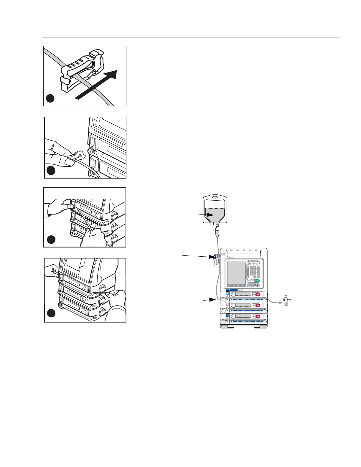
Operating Instructions Loading the Administration Set
B
C
D
A
INTO
PUMP
B
Figure 4-19 Loading the
Administration Set
Figure 4-20 Orientation of Source Container, Pump, and Patient
SOURCE
CONTAINER
FROM SOURCE
CONTAINER
TO PAT IEN T
TUBING
GUIDE (triple
channel pumps
only)
2. Close the keyed slide clamp on the administration set so it occludes
the tubing to prevent free flow. Hold the keyed slide clamp with the
notched side up (Figure 4-19A).
3. Insert the keyed slide clamp into the slot in the pump (Figure 4-19B).
4. Pull the administration set taut and slide it all the way into and along
the tubing channel (Figure 4-19C). The pump pulls in the keyed slide
clamp, then loads the administration set into the pumping
mechanism (Figure 4-19D). The pump module displays
then
STOPPED.
LOADING ,
Note:
Tube Misloaded
Alarm
A Tube Misloaded alarm will occur if the tubing is not
loaded properly. See page 8-15 for more information
about the
Tube Misloaded alarm.
5. Confirm that the tubing coming from the source container enters the
pump module on the left side, and the tubing exiting the pump on the
right side goes to the patient as shown in Figure 4-20.
A
E
G
L
U
L
E
O
C
G
N
U
A
A
I
R
D
.
E
X
C
C
X
E
6. Open the regulating clamp. Verify that no solution is flowing (no free
071960491 COLLEAGUE CXE VOLUMETRIC INFUSION PUMP OPERATOR’S MANUAL 4-17
7. Attach the primed administration set to the patient access site.
flow drops falling in the drip chamber and/or no flow from the end of
the administration set).
Page 72

4 Using the Optional Prime Function
!
WARNING
!
!
WARNING
!
8. For triple channel pumps only: Arrange the tubing in the tubing
guide according to pump channel.
If flow is observed when tubing is loaded but the pump is not running, close the
regulating clamp immediately. Ensure that all steps have been properly
performed. If flow is still observed, remove the pump from service and contact
Baxter-trained, qualified personnel.
Using the Optional Prime Function
Overview
The optional Prime function can be used to assist clinicians in preparing
a primary administration set for infusion.
If Prime is not displayed on the Programming Modes menu, this feature
has not been enabled.
Do not connect the administration set to the patient when priming.
Priming the Administration Set
Note: The administration set’s drip chamber should be at least one third
full prior to using the prime function to ensure that fluid will enter
the administration set.
Note: Prime cannot be selected if an
Note: Air detection is disabled when priming is active.
Air alarm is active.
4-18 COLLEAGUE CXE VOLUMETRIC INFUSION PUMP OPERATOR’S MANUAL 071960491
Page 73

Operating Instructions Using the Optional Prime Function
Figure 4-21 Programming
Modes Menu
Figure 4-22 Ready to Prime
1. Load the administration set into the desired pump channel as
described in “Loading the Administration Set,” 4-16.
2. From the Main Display, access the Programming screen:
For single channel pumps: For triple channel pumps:
press the Primary soft key or
Rate or Volume keys.
the
3. From the Programming screen, press the Change Mode soft key.
press the desired
Select
key.
Channel
The Programming Modes menu is displayed (Figure 4-21).
4. Use the ×Ø keys to highlight Prime (under Functions), then press
the
Select soft key.
The PRIME WARNING pop-up (Figure 4-22) is displayed.
071960491 COLLEAGUE CXE VOLUMETRIC INFUSION PUMP OPERATOR’S MANUAL 4-19
Page 74

4 Using the Optional Prime Function
Figure 4-23 Prime Active
5. Press and hold the Prime soft key until all the air is expelled from the
administration set. The PRIME ACTIVE pop-up (Figure 4-23) is
displayed while the
key when finished priming.
6. When priming has been completed, press the Done soft key to exit
the priming function and return to the channel’s primary infusion
program screen.
Prime soft key is pressed. Release the Prime soft
4-20 COLLEAGUE CXE VOLUMETRIC INFUSION PUMP OPERATOR’S MANUAL 071960491
Page 75

Operating Instructions Primary Infusions
Figure 4-24 Main Display Screen
!
WARNING
!
Programming an Infusion
Before starting an infusion, the administration set must be fully loaded.
If an administration set has not been loaded and START is
pressed, a Tube Not Loaded alarm will occur.
If an administration set is still loading and START is pressed, a
Tube Loading in Progress alarm will occur.
See Table 8-1, “Troubleshooting Alarm Messages,” on page 8-13 for
more information about these alarms.
Primary Infusions
Programming a Primary Rate-Volume Infusion
1. From the Main Display screen (Figure 4-24):
For single channel pumps: For triple channel pumps:
press the Primary soft key or
Rate or Volume keys.
the
press the desired
Select
key.
Channel
The display then changes to the Rate-Volume programming screen
(Figure 4-25). The Rate field is highlighted.
Note:
Channel Stopped
Alert
If a pump channel is powered on and no keys are
pressed for two minutes, a
occurs. Either continue programming, start the infusion, or place the channel in standby to clear the alert.
There may be periods of no flow for flow rates less than
or equal to 1mL/hr.
Channel Stopped alert
071960491 COLLEAGUE CXE VOLUMETRIC INFUSION PUMP OPERATOR’S MANUAL 4-21
Page 76

4 Primary Infusions
Figure 4-25 Rate-Volume
Programming Screen
!
WARNING
!
Figure 4-26 Secondary Infusion
Programmed Pop-up
2. Enter the flow rate using the numeric keypad.
3. Press the Vol key or use the ×Ø keys to highlight the Volume to be
infused field.
Do not enter a Volume to be infused greater than the
amount of fluid available in the container.
4. Enter the volume to be infused using the keypad.
Note:
Optional Labels
5. When all infusion parameters have been entered, verify that:
pump programming matches the label on the source container and
An optional label may also be selected. See “Selecting
a Label” on page 4-23 for details.
the physician’s order
the loaded administration set is connected to the correct source
container and administration route for the programmed infusion
6. Press the Confirm Primary soft key.
Note:
Unconfirmed
Primary Program
7. Press the START key to start the infusion.
If the START key is pressed before pressing the
Confirm Primary soft key, an
Program
the prompt line.
alarm occurs and a message is displayed on
Unconfirmed Primary
If a secondary infusion has been programmed but not started, a
pop-up appears (Figure 4-26) warning that a primary infusion is
about to start when a secondary infusion has been programmed.
Press the
Done soft key to clear the warning and do one of the
following:
4-22 COLLEAGUE CXE VOLUMETRIC INFUSION PUMP OPERATOR’S MANUAL 071960491
Press the Secondary soft key to access the secondary infusion
programming screen. For more information about secondary
infusions, see “Secondary Infusions,” 4-45.
Press the START key again to start the primary infusion.
Page 77
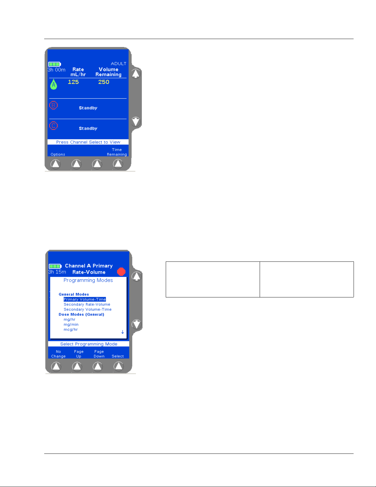
Operating Instructions Primary Infusions
Figure 4-27 Main Display,
Primary Running
Figure 4-28 Programming Modes
Menu
When the primary infusion starts, the RUNNING LED on the Pump
Module lights and a moving drop icon is shown on the Main Display
(Figure 4-27). Confirm that flow is occurring by observing drops
falling into the drip chamber.
Selecting a Label
Note:
Programming
Tips
If an incorrect value is entered during programming,
press the CLR key to clear the field, then enter the correct value.
If values that exceed the allowable range are programmed,
of Range
pressed.
If the rate and volume entered results in a time duration exceeding 99:59, the time duration will be displayed as **:**.
High or Low will be displayed and an Out
alarm will occur when the START key is
If the Label Library feature is enabled, use the procedure below to select
an informational label for an infusion.
1. Access the desired programming screen:
For single channel pumps: For triple channel pumps:
press the Primary or
Secondary soft key.
2. Press the Change Mode soft key. The Programming Modes menu is
press the desired
Select
key.
Channel
displayed (Figure 4-28).
3. Highlight Label Line (under Functions) using the ×Ø keys, then
press the
Select soft key.
A list of labels and their abbreviations is displayed as shown in
Figure 4-29. If the list consists of more than one screen, use the
Up
and Page Down soft keys to view the next screen of labels.
Page
071960491 COLLEAGUE CXE VOLUMETRIC INFUSION PUMP OPERATOR’S MANUAL 4-23
Page 78

4 Primary Infusions
Figure 4-29 Label List
4. Highlight the label to be selected using the ×Ø keys, then press the
Select soft key. When the Select soft key is pressed, the
Programming screen is displayed, showing the selected label.
Figure 4-29 shows the label Maintenance Line highlighted on the
list of available labels.
Note:
COLLEAGUE
GUARDIAN
Labels
Note:
Clearing Labels
Note:
Appropriate
Label Use
Labels configured using the COLLEAGUE GUARDIAN
feature do not appear in the label list.
To clear a label, use the same procedure, but select
No Label from the label list. No Label always
appears first in the label list.
Confirm that the selected label is appropriate for the
medication/solution infusing on that channel.
4-24 COLLEAGUE CXE VOLUMETRIC INFUSION PUMP OPERATOR’S MANUAL 071960491
Page 79

Operating Instructions Primary Infusions
Figure 4-30 Programming Modes
Menu
Figure 4-31 Volume-Time
Programming Screen
Programming a Primary Volume-Time Infusion
1. From the Main Display screen:
For single channel pumps: For triple channel pumps:
press the Primary soft key. press the desired Channel
Select
key.
2. Press the Change Mode soft key. The Programming Modes menu is
displayed (Figure 4-30).
3. Highlight Primary Volume-Time, then press the Select soft key.
The Volume-Time Programming screen is displayed (Figure 4-31).
4. Enter the Volume to be infused using the keypad.
5. Highlight Time Duration using the ×Ø keys. Use the keypad to
enter the time period for the infusion in hours and minutes. The
pump automatically calculates the flow rate.
The pump may round off the calculated rate. If this occurs, the pump
then calculates the time duration based on the rounded rate. When
Confirm Primary soft key is pressed, the calculated time is
the
displayed as Time Remaining instead of the time duration entered.
The time duration must be less than or equal to 99:59. If a time
greater than 99:59 is entered, **:** is displayed.
6. Verify that the values are appropriate. After the time duration is
programmed, the Volume to be infused or Rate can be changed.
The pump then calculates the new time duration automatically.
Note:
Optional Labels
7. Press the Confirm Primary soft key.
Note:
Unconfirmed
Primary Program
An optional label may also be selected. See “Selecting
a Label” on page 4-23 for details.
If the START key is pressed before pressing the
Confirm Primary soft key, an
Program
the prompt line.
alarm occurs and a message is displayed on
Unconfirmed Primary
071960491 COLLEAGUE CXE VOLUMETRIC INFUSION PUMP OPERATOR’S MANUAL 4-25
8. Press the START key to start the infusion.
If a secondary infusion has been programmed but not started, a
pop-up appears (Figure 4-26) warning that a primary infusion is
about to start when a secondary infusion has been programmed. See
step 7 on page 4-22 for more information.
Page 80

4 Primary Infusions
Figure 4-32 Colleague Guardian
Soft Key
Programming a Primary COLLEAGUE GUARDIAN Infusion (Rate-Volume)
1. From the Main Display, access the Programming screen:
For single channel pumps: For triple channel pumps:
press the Primary soft key or
the
Rate or Volume keys.
2. From the Programming screen, press the Colleague Guardian soft
press the desired
Select
key.
Channel
key (Figure 4-32).
4-26 COLLEAGUE CXE VOLUMETRIC INFUSION PUMP OPERATOR’S MANUAL 071960491
Page 81

Operating Instructions Primary Infusions
Figure 4-33 COLLEAGUE
GUARDIAN Label List
Figure 4-34 COLLEAGUE
GUARDIAN Programming Screen—
Rate-Volume Label
The labels for which COLLEAGUE GUARDIAN limits have been
defined are displayed in a pop-up window (Figure 4-33). A yellow
triangle beside the label indicates that the standard concentration can
be edited if clinically necessary.
3. Use the ×Ø keys (and Page Up/Page Down soft keys if necessary)
to highlight the desired label, then press the
Select soft key.
The programming mode changes to the mode configured for the
selected label, and the Rate field is filled with the configured value
(Figure 4-34).
071960491 COLLEAGUE CXE VOLUMETRIC INFUSION PUMP OPERATOR’S MANUAL 4-27
Page 82

4 Primary Infusions
Figure 4-35 COLLEAGUE
GUARDIAN Limits Display Pop-up
Figure 4-36 Limits Warning Pop-up
4. (Optional) To view a pop-up window (Figure 4-35) showing the
limits programmed for the label, highlight the Rate field, then press
View Limits soft key. Press the Done soft key to close the pop-up
the
and continue.
5. (Optional) To modify the rate if clinically appropriate, use the × key
to highlight the Rate field, then use the numeric keypad to enter a
different rate.
6. Use the Ø key to highlight the The Volume To Be Infused field.
7. Enter the desired volume using the numeric keypad.
Note:
Rate Outside
Limits
8. Verify that the values are appropriate and:
that pump programming matches the label on the source
If a rate is entered that is outside the rate limits of the
pump or the current PERSONALITY feature set,
Low is displayed in the Rate field. Reprogram so
or
that the rate is within the limits.
container and the physician’s order
that the loaded administration set is connected to the correct
source container and administration route for the programmed
infusion
9. Then press the Confirm Primary soft key.
If the values entered result in a dose that is outside the
COLLEAGUE GUARDIAN rate limits, a Limits Warning pop-up is
displayed, showing the flow rate entered and the defined rate limits
(Figure 4-36). If this occurs, do one of the following:
Press Cancel Rate (Ø key) to cancel the rate and return to the
programming screen, then enter a rate that is within the rate
limits.
High
4-28 COLLEAGUE CXE VOLUMETRIC INFUSION PUMP OPERATOR’S MANUAL 071960491
If the clinical decision is to proceed with the override of the
COLLEAGUE GUARDIAN limits, press
Accept Rate (× key)
to accept the out-of limits flow rate and continue with the
infusion as programmed.
Page 83

Operating Instructions Primary Infusions
Figure 4-37 Infusion with
COLLEAGUE GUARDIAN Limit
Override
Figure 4-38 COLLEAGUE
GUARDIAN Label List
10. Press the START key to begin the infusion. COLLEAGUE
GUARDIAN infusions are indicated by the mortar and pestle icon
next to the label on the Main Display screen (Figure 4-37)
Note:
Overriding
COLLEAGUE
GUARDIAN
Limits
If the clinical decision was to override the
COLLEAGUE GUARDIAN limits, the rate is displayed
in red on a yellow highlight indicating that the
programmed dose is outside of the COLLEAGUE
GUARDIAN limits.
If a secondary infusion has been programmed but not started, a
pop-up appears (Figure 4-26) warning that a primary infusion is
about to start when a secondary infusion has been programmed. See
step 7 on page 4-22 for more information.
Programming a Primary COLLEAGUE GUARDIAN Infusion (Non-Weight-Based)
1. From the Main Display, access the Programming screen:
For single channel pumps: For triple channel pumps:
press the Primary soft key or
the
Rate or Volume keys.
2. From the Programming screen, press the Colleague Guardian soft
press the desired
Select
key.
Channel
key.
The labels for which COLLEAGUE GUARDIAN limits have been
configured are displayed in a pop-up window (Figure 4-38). A
yellow triangle beside the label indicates that the standard
concentration can be edited if clinically necessary.
3. Use the ×Ø keys (and Page Up/Page Down soft keys if necessary)
to highlight the desired label, then press the
Select soft key.
071960491 COLLEAGUE CXE VOLUMETRIC INFUSION PUMP OPERATOR’S MANUAL 4-29
Page 84

4 Primary Infusions
Figure 4-39 COLLEAGUE
GUARDIAN Programming Screen—
Non-Weight-Based Label
Figure 4-40 COLLEAGUE
GUARDIAN Limits Display Pop-up
The programming mode changes to the mode configured for the
selected label, and the Drug Amount, Diluent Volume, and
Concentration fields are filled with the defined values. The
Volume To Be Infused field is filled with the standard Diluent
Volume (Figure 4-39).
4. (Optional) To view a pop-up window (Figure 4-40) showing the
limits programmed for the label, highlight the Concentration or
Dose fields, then press the
View Limits soft key. Press the Done
soft key to close the pop-up and continue. Concentration limits
cannot be overridden.
5. (Optional) If the label is set up to allow non-standard concentration
programming, the drug amount, diluent volume, and concentration
can be changed by using the
×Ø keys to highlight the appropriate
field and entering new values using the numeric keypad.
6. Use the Ø key to highlight the Dose field.
7. Enter the desired dose (or change the default dose, if clinically
appropriate) using the numeric keypad. The pump displays the dose
and calculated flow rate.
Note:
Rate Outside
Limits
If a dose is entered that results in a rate outside the
rate limits of the current PERSONALITY feature set,
High or Low is displayed in the Rate field. Reprogram
so that the rate is within the limits.
4-30 COLLEAGUE CXE VOLUMETRIC INFUSION PUMP OPERATOR’S MANUAL 071960491
Page 85

Operating Instructions Primary Infusions
Figure 4-41 Non-Standard
COLLEAGUE GUARDIAN
Programming—Non-Weight-Based
Figure 4-42 Limits Warning Pop-up
If values are changed so that the resulting drug amount, diluent
volume, or concentration differs from the defined values, the
changed values are indicated by white triangles beside them (Figure
4-41).
8. Verify that all values are appropriate and:
that pump programming matches the label on the source
container and the physician’s order
that the loaded administration set is connected to the correct
source container and administration route for the programmed
infusion
9. Press the Confirm Primary soft key.
If the values entered result in a dose that is outside the
COLLEAGUE GUARDIAN dose limits, a Limits Warning pop-up is
displayed, showing the calculated dose and the dose limits (Figure
4-42). If this occurs, do one of the following:
Press Cancel Dose (Ø key) to cancel the dose and return to the
programming screen, then enter a dose that is within the preset
limits.
If the clinical decision is to proceed with the override of the
COLLEAGUE GUARDIAN limits, press
Accept Dose (× key)
to accept the out-of limits dose and continue with the infusion as
programmed.
071960491 COLLEAGUE CXE VOLUMETRIC INFUSION PUMP OPERATOR’S MANUAL 4-31
Page 86

4 Primary Infusions
Figure 4-43 Infusion with
COLLEAGUE GUARDIAN Limit
Override
Figure 4-44 COLLEAGUE
GUARDIAN Label List
10. Press the START key to begin the infusion. COLLEAGUE
GUARDIAN infusions are indicated by the mortar and pestle icon
next to the channel on the Main Display screen.
A yellow triangle is displayed beside the label name if the drug
amount, diluent, or concentration was changed to deviate from the
standard COLLEAGUE GUARDIAN settings.
Note:
Overriding
COLLEAGUE
GUARDIAN
Limits
If the clinical decision was to override the
COLLEAGUE GUARDIAN limits, the dose and
programming mode are displayed in red on a yellow
highlight (Figure 4-43) indicating that the programmed
dose is outside of the COLLEAGUE GUARDIAN limits.
If a secondary infusion has been programmed but not started, a
pop-up appears (Figure 4-26) warning that a primary infusion is
about to start when a secondary infusion has been programmed. See
step 7 on page 4-22 for more information.
Programming a Primary COLLEAGUE GUARDIAN Infusion (Weight-Based)
1. From the Main Display, access the Programming screen:
For single channel pumps: For triple channel pumps:
press the Primary soft key or
Rate or Volume keys.
the
press the desired
Select
key.
Channel
2. From the Programming screen, press the Colleague Guardian soft
key.
The labels for which COLLEAGUE GUARDIAN limits have been
configured are displayed in a pop-up window (Figure 4-44). A
yellow triangle beside the label indicates that the standard
concentration can be edited if clinically necessary
3. Use the ×Ø keys (and Page Up/Page Down soft keys if necessary)
to highlight the desired label, then press the
4-32 COLLEAGUE CXE VOLUMETRIC INFUSION PUMP OPERATOR’S MANUAL 071960491
Select soft key.
Page 87

Operating Instructions Primary Infusions
Figure 4-45 COLLEAGUE
GUARDIAN Programming Screen—
Weight-Based Label
Figure 4-46 Weight Unit Pop-up
The programming mode changes to the mode configured for the
selected label, and the Drug Amount, Diluent Volume, and
Concentration fields are filled with the defined values. The
Weight field is highlighted (Figure 4-45). If a default dose has been
configured, it appears in the Dose field.
4. For small patients, weight can be entered in grams (or ounces) if
appropriate. To change weight units, highlight the Weight field,
press the
highlight the desired weight unit, then press the
Units soft key to display the weight units list (Figure 4-46),
Select soft key.
5. Enter patient weight using the numeric keypad.
Depending on how the pump has been configured at the facility, the
kg or lbs field may not be available for data entry. Fields not
available for data entry appear as shaded.
The pump calculates and displays the values for the remaining fields
based on the entered patient weight (Figure 4-47).
071960491 COLLEAGUE CXE VOLUMETRIC INFUSION PUMP OPERATOR’S MANUAL 4-33
Page 88

4 Primary Infusions
Figure 4-47 Calculated Values
Figure 4-48 View Limits Pop-up
6. Use the Ø key to highlight the Dose field.
7. Enter the desired dose (or change the default dose, if clinically
appropriate) using the numeric keypad. The pump displays the dose
and calculated flow rate.
8. (Optional) To view a pop-up window (Figure 4-48) showing the
limits programmed for the label, highlight the Concentration or
Dose fields, then press the
soft key to close the pop-up and continue. Concentration limits
cannot be overridden.
View Limits soft key. Press the Done
9. (Optional) If the label is set up to allow non-standard concentration
programming, the drug amount, diluent volume, and concentration
can be changed by using the
×Ø keys to highlight the appropriate
field and entering new values using the numeric keypad.
Note:
Rate Outside
Limits
If the entries result in a rate outside the rate limits of
the current PERSONALITY feature set,
is displayed in the Rate field. Reprogram other values
so that the rate is within the limits.
High or Low
4-34 COLLEAGUE CXE VOLUMETRIC INFUSION PUMP OPERATOR’S MANUAL 071960491
Page 89

Operating Instructions Primary Infusions
Figure 4-49 Non-Standard
COLLEAGUE GUARDIAN
Programming—Weight-Based
If values are changed so that the resulting drug amount, diluent
volume, or concentration is non-standard, the changed values are
indicated by white triangles beside them (Figure 4-49).
10. Verify that all values are appropriate and:
that pump programming matches the label on the source
container and the physician’s order
that the loaded administration set is connected to the correct
source container and administration route for the programmed
infusion
11. Press the Confirm Primary soft key.
If the dose entered is outside the COLLEAGUE GUARDIAN dose
limits, a Limits Warning pop-up is displayed, showing the calculated
dose and the dose limits. If this occurs, do one of the following:
Press Cancel Dose (Ø key) to cancel the dose and return to the
programming screen, then enter a dose that is within the preset
limits.
If the clinical decision is to proceed with the override of the
COLLEAGUE GUARDIAN limits, press
Accept Dose (× key)
to accept the out-of limits dose and continue with the infusion as
programmed.
Note:
Weight
Differences
(Triple Channel
Pumps Only)
The pump will detect weight differences and display a
pop-up window for the following:
• If a patient weight is entered on one channel
and a different patient weight is entered on
another channel.
• If a patient weight is entered on one channel
and the same patient weight is entered on
another channel using different units (lbs on
one channel and kg on the other for example),
and the units conversion causes the weights to
appear slightly different on the display.
The pop-up window will ask to confirm the difference. If
the difference was not intentional, the weight can be
modified on the programming screen.
Press the Confirm soft key if the weight difference is
acceptable; if not, press the appropriate Channel
Select soft key to return to the programming screen
and change the weight.
071960491 COLLEAGUE CXE VOLUMETRIC INFUSION PUMP OPERATOR’S MANUAL 4-35
Page 90

4 Primary Infusions
Figure 4-50 Main Display with
Non-Standard Concentration
Figure 4-51 Programming Modes
12. Press the START key to begin the infusion.COLLEAGUE
GUARDIAN infusions are indicated by a mortar and pestle icon next
to the channel on the Main Display screen
A yellow triangle is displayed beside the label name if the drug
amount, diluent, or concentration was changed to deviate from the
standard COLLEAGUE GUARDIAN settings.
Note:
Overriding
COLLEAGUE
GUARDIAN
Limits
If the clinical decision was to override the
COLLEAGUE GUARDIAN limits, the dose and
programming mode are displayed in red on a yellow
highlight, indicating that the programmed dose is
outside of the COLLEAGUE GUARDIAN limits.
If a secondary infusion has been programmed but not started, a
pop-up appears (Figure 4-26) warning that a primary infusion is
about to start when a secondary infusion has been programmed. See
step 7 on page 4-22 for more information.
Programming a Primary Dose Mode Infusion (Non-Weight Based)
1. From the Main Display, access the Programming screen:
For single channel pumps: For triple channel pumps:
press the Primary soft key or
Rate or Volume keys.
the
press the desired
Select
Channel
key.
2. From the Programming screen, press the Change Mode soft key.
The Programming Modes menu is displayed (Figure 4-51).
3. Use the ×Ø and/or Page Up, Page Down soft keys to highlight the
appropriate dose formula selection, if configured. Some or all of the
following dose modes may be available depending on pump
configuration at the facility:
• Colleague Guardian
• mg/hr
• mg/min
• mcg/hr
• units/hr
• mcg/min
• mEq/hr
4-36 COLLEAGUE CXE VOLUMETRIC INFUSION PUMP OPERATOR’S MANUAL 071960491
Page 91

Operating Instructions Primary Infusions
Figure 4-52 Dose Programming
Screen
Figure 4-53 Units Change List
4. Press the Select soft key to display the Dose Programming screen
(Figure 4-52).
Any dose parameters retained in memory are displayed.
To use the existing parameters, press the Confirm Primary soft
key.
To clear the parameters, enter new values or press the CLR key
for each value.
5. Check the units of measure displayed for the Drug Amount. To
enter the drug amount in units other than the one displayed:
5.1 Press the Units soft key to display the Units Change list
(Figure 4-53).
5.2 Use the ×Ø keys to highlight the desired units.
5.3 Press the Select soft key to change to the highlighted units.
6. Enter the desired Drug Amount using the numeric keypad and press
Ø key to highlight the Diluent Volume field.
the
071960491 COLLEAGUE CXE VOLUMETRIC INFUSION PUMP OPERATOR’S MANUAL 4-37
Page 92

4 Primary Infusions
Figure 4-54 Value High Prompt
Figure 4-55 Enter Volume to be
Infused
7. Enter the desired Diluent Volume using the numeric keypad.
Note:
Concentration
Too High
8. Use the Ø key to highlight the Dose field.
9. Enter the desired dose using the numeric keypad.
If desired, the Dose field can be bypassed by using the
The pump calculates the concentration as diluent volume is entered. In Figure 4-54, the concentration is too
high because the pump is calculating as the numbers
are being entered. This
the rest of the digits are entered and the pump recalculates the concentration.
High condition is cleared after
Ø key and
entering the Rate value first. The pump then calculates the Dose.
10. Use the Ø key to highlight the Volume to be infused field (Figure
4-55).
The Volume to be infused field defaults to the Diluent Volume.
The Volume to be infused may be less than the Diluent Volume, but
cannot be greater than the Diluent Volume.
11. If appropriate, change the Volume to be infused value.
Note:
Optional Labels
An optional label may also be selected. See “Selecting
a Label” on page 4-23 for details.
4-38 COLLEAGUE CXE VOLUMETRIC INFUSION PUMP OPERATOR’S MANUAL 071960491
Page 93

Operating Instructions Primary Infusions
Figure 4-56 Unconfirmed Primary
Program
Figure 4-57 Main Display
12. Verify that all values are appropriate and:
that pump programming matches the label on the source
container and the physician’s order
that the loaded administration set is connected to the correct
source container and administration route for the programmed
infusion
13. Press the Confirm Primary soft key.
Note:
Unconfirmed
Primary Program
14. Press the appropriate START key to begin the infusion. The Main
If the START key is pressed before pressing the
Confirm Primary soft key to verify the parameters, an
Unconfirmed Primary Program alarm occurs and a
message is displayed on the prompt line (Figure 4-56).
Display screen shows the rate, volume remaining, and the dose
(Figure 4-57).
If a secondary infusion has been programmed but not started, a
pop-up appears (Figure 4-26) warning that a primary infusion is
about to start when a secondary infusion has been programmed. See
step 7 on page 4-22 for more information.
071960491 COLLEAGUE CXE VOLUMETRIC INFUSION PUMP OPERATOR’S MANUAL 4-39
Page 94

4 Primary Infusions
Figure 4-58 Programming Modes
Figure 4-59 Weight-Based Dose
Programming Modes
Programming a Primary Dose Mode Infusion (Weight-Based)
1. From the Main Display, access the Programming screen:
For single channel pumps: For triple channel pumps:
press the Primary soft key or
the
Rate or Volume keys.
2. From the Programming screen, press the Change Mode soft key.
press the desired
Select
key.
Channel
The Programming Modes menu is displayed (Figure 4-58).
3. Use the ×Ø and/or Page Up, Page Down soft keys to highlight the
appropriate dose mode selection (Figure 4-59). Some or all of the
following dose modes may be available depending on pump
configuration at the facility:
• mcg/kg/min
• mg/kg/hr
• mEq/kg/hr
• mg/kg/min
• mcg/kg/hr
• units/kg/hr
4-40 COLLEAGUE CXE VOLUMETRIC INFUSION PUMP OPERATOR’S MANUAL 071960491
Page 95

Operating Instructions Primary Infusions
Figure 4-60 Dose Programming
Screen
Figure 4-61 Units Change List
4. Press the Select soft key to display the Dose Programming screen
(Figure 4-60), which allows entry of patient weight.
Any dose parameters retained in memory are displayed.
To use the existing parameters, press the Confirm Primary soft
key.
To clear the parameters, enter new values or press the CLR key
for each value.
5. Check the units of measure displayed for the Drug Amount. To
enter the drug amount in units other than the one displayed:
5.1 Press the Units soft key to display the Units Change list
(Figure 4-61).
5.2 Use the ×Ø keys to highlight the desired units.
5.3 Press the Select soft key to change to the highlighted units.
6. Enter the desired Drug Amount using the numeric keypad and press
Ø key to highlight the Diluent Volume field.
the
071960491 COLLEAGUE CXE VOLUMETRIC INFUSION PUMP OPERATOR’S MANUAL 4-41
Page 96
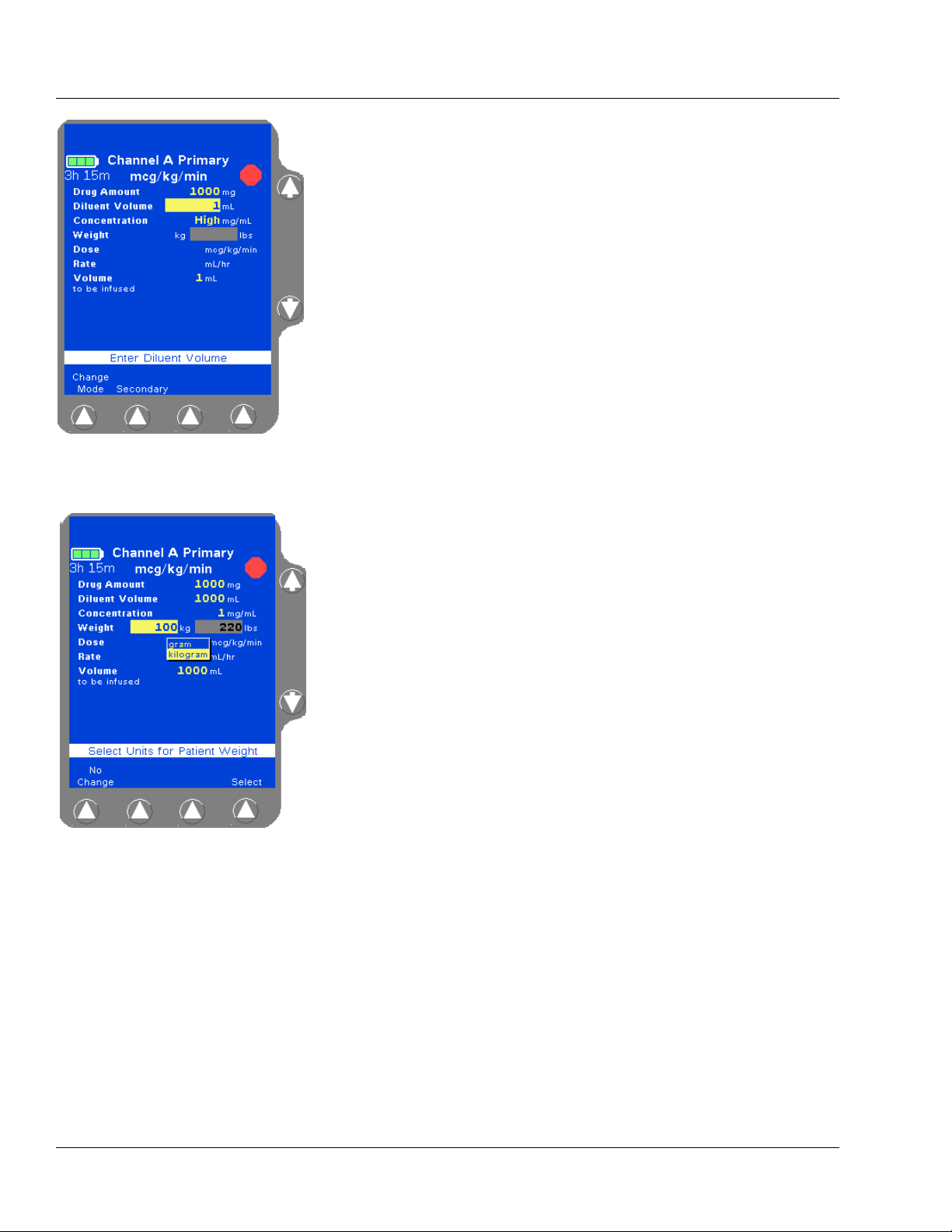
4 Primary Infusions
Figure 4-62 Value High Prompt
Figure 4-63 Enter Weight
7. Enter the desired Diluent Volume using the numeric keypad.
Note:
Concentration
Too High
8. Highlight the Weight field and enter the patient’s weight using the
The pump calculates the concentration as diluent volume is entered. In Figure 4-62, the concentration is too
high because the pump is calculating as the numbers
are being entered. This
the rest of the digits are entered and the pump recalculates the concentration.
High condition is cleared after
numeric keypad (Figure 4-63). Depending on how the pump has
been configured, the kg or lbs field may not be available for data
entry.
Fields not available for data entry appear as shaded.
For small patients, weight can be entered in grams (or ounces) if
appropriate. Highlight the Weight field, press the
Units soft key
to display the weight units list (Figure 4-63), highlight the desired
weight unit, then press the
Select soft key.
4-42 COLLEAGUE CXE VOLUMETRIC INFUSION PUMP OPERATOR’S MANUAL 071960491
Page 97

Operating Instructions Primary Infusions
Figure 4-64 Example of
Out-of-Range Weights
Figure 4-65 Unconfirmed
Primary Program
If the weight is outside the allowed weight limits, the word Low
or High is displayed (Figure 4-64). Select a weight within limits.
Note:
Weight Limits
9. Use the Ø key to highlight the Dose field.
10. Enter the desired dose using the numeric keypad.
If desired, the Dose field can be bypassed by using the
The pump is capable of accepting patient weights
within the range 0.2 to 600 kg (0.44 to 1322 lb). However, the pump’s current PERSONALITY feature set
may have been configured with a narrower weight
range. Use the Options soft key on the Main Display
to view the settings for the current PERSONALITY feature set if desired.
Ø key and
entering the Rate value first. The pump then calculates the Dose.
11. Use the Ø key to highlight the Volume to be infused field.
The Volume to be infused field defaults to the Diluent Volume.
The Volume to be infused may be less than the Diluent Volume, but
cannot be greater than the Diluent Volume.
12. If appropriate, change the Volume to be infused value.
Note:
Optional Labels
13. Verify that all values are appropriate and:
that pump programming matches the label on the source
An optional label may also be selected. See “Selecting
a Label” on page 4-23 for details.
container and the physician’s order
that the loaded administration set is connected to the correct
source container and administration route for the programmed
infusion
14. Press the Confirm Primary soft key.
Note:
Unconfirmed
Primary Program
If the START key is pressed before pressing the
Confirm Primary soft key to verify the parameters, an
Unconfirmed Primary Program alarm occurs and a
message is displayed on the prompt line (Figure 4-65).
071960491 COLLEAGUE CXE VOLUMETRIC INFUSION PUMP OPERATOR’S MANUAL 4-43
Page 98

4 Primary Infusions
Figure 4-66 Weight Difference
Confirmation Pop-up (Triple
Channel Pumps Only)
Figure 4-67 Main Display
Note:
Weight
Differences
(Triple Channel
Pumps Only)
15. Press the START key to begin the infusion. The Main Display screen
The pump will detect weight differences and display a
pop-up window for the following:
• If a patient weight is entered on one channel
and a different patient weight is entered on
another channel.
• If a patient weight is entered on one channel
and the same patient weight is entered on
another channel using different units (lbs on
one channel and kg on the other for example),
and the units conversion causes the weights to
appear slightly different on the display.
The pop-up window (Figure 4-66) will ask to confirm
the difference. If the difference was not intentional, the
weight can be modified on the programming screen.
Press the Confirm soft key if the weight difference is
acceptable; if not, press the appropriate Channel
Select soft key to return to the programming screen
and change the weight.
shows the rate, volume remaining, and the dose (Figure 4-67).
If a secondary infusion has been programmed but not started, a
pop-up appears (Figure 4-26) warning that a primary infusion is
about to start when a secondary infusion has been programmed. See
step 7 on page 4-22 for more information.
4-44 COLLEAGUE CXE VOLUMETRIC INFUSION PUMP OPERATOR’S MANUAL 071960491
Page 99

Operating Instructions Secondary Infusions
!
WARNING
!
!
WARNING
!
!
WARNING
!
Secondary Infusions
This optional programming function allows the pump to deliver fluid
from a second source container at a rate and volume that is independent
of the primary infusion. When the secondary infusion is complete, the
pump automatically switches to the programmed primary rate if a
confirmed primary infusion exists.
Note:
While Primary is
Running
When using primary administration sets with check valves and secondary
administration sets for secondary infusions, factors including but not limited to
programmed infusion rates, fluid viscosity, source containers (type and size), and
head height differences may influence system performance. Flow rates greater
than 350 mL/hr may cause fluid to be siphoned from the primary source container
during infusions, causing concurrent flow.
Use only CONTINU-FLO standard administration sets equipped with keyed slide
clamps and labeled as COLLEAGUE pump compatible or denoted with an “s” in
the product code as the primary fluid line when administering a secondary
medication/solution. See “Recommended Administration Sets,” 4-15. Carefully
follow the directions on the primary and secondary administration set labels.
When using the secondary infusion feature ensure:
A secondary infusion can be programmed while a primary infusion is running. A
alert message will be displayed with an audible
ary
alert tone.
Programming Second-
• the medication/solution in the secondary source container is
compatible with the medication/solution in the primary source
container.
• the secondary administration set is connected to the appropriate
injection site on the CONTINU-FLO administration set.
• the interruption of the primary infusion is clinically appropriate for
the duration of the secondary infusion.
• the infusion runs from a secondary source container and not from a
primary container.
Failure to properly lower the primary container by fully extending the hanger
increases the potential for concurrent flow. Concurrent flow leads to
over-infusion of the primary infusion and under-infusion of the secondary
infusion.
071960491 COLLEAGUE CXE VOLUMETRIC INFUSION PUMP OPERATOR’S MANUAL 4-45
Page 100

4 Secondary Infusions
!
WARNING
!
!
WARNING
!
!
WARNING
!
Always read and follow the instructions which accompany the source container
and administration sets you are using. Carefully follow any label copy
instructions for loading, removing, and reloading the set, as well as the
recommended set change interval. For optimal pump performance, set use
should not exceed the change interval shown on the set's label copy or 72 hours,
whichever is less.
COLLEAGUE pumps do not support same-bag loading dose or bolus as it may
lead to an over-infusion, under-infusion, or interruption of therapy.
Failure to open the roller clamp on a secondary set when starting a secondary
infusion will cause a delay of the secondary infusion and an over-infusion of the
primary infusion.
Preparing a Secondary Infusion Set
1. Prepare solution containers and administration sets.
2. Lower the primary container using the hanger provided with the
secondary set. Ensure the hanger is fully extended.
3. Load the CONTINU-FLO administration set into the desired pump
channel as described in “Loading the Administration Set,” 4-16.
4. If desired, program the primary infusion for the selected channel.
Programming a Secondary Rate-Volume Infusion
1. From the Main Display screen:
For single channel pumps: For triple channel pumps:
press the Secondary soft key. press the desired Channel
Select
Secondary soft key.
key, then press the
4-46 COLLEAGUE CXE VOLUMETRIC INFUSION PUMP OPERATOR’S MANUAL 071960491
 Loading...