

Baxi Wonderfire AF16NV RC, Wonderfire AC16XL, Wonderfire AF16XL RC, Wonderfire AF16XL, Wonderfire AC16XL RC Conversion Manual
...Page 1

5111124/01
CONVERSION GUIDE
This guide must be read in conjunction with the
We trust that these instructions give sufficient details to enable this appliance to be
converted and installed satisfactorily. However, if further information is required, our
Please telephone 08706 061 065 (National call rates apply in the United Kingdom)
This kit is for the following conversions: -
AF16NV - 9500298 TO AF16XL - 9500322
AC16NV - 9500296 TO AC16XL - 9500323
AF16NV RC - 9500370 TO AF16XL RC - 9500372
AC16NV RC - 9500371 TO AC16XL RC - 9500373
Installer guide supplied with the fire.
Wonderfire Technical Helpline will be pleased to help.
In the Republic of Ireland telephone 0044 8706 061 065
This guide to be left with the owner
© Baxi Heating U.K. Ltd.
Page 2
CONVERSION GUIDE
LIST OF CONTENTS
The kit contains the following: 1 Conversion guide
4 Overlay labels, only one of which will be used during each conversion.
1 Injector Cat 82- size 702
BURNER CONVERSION
1. Isolate the appliance from the gas supply. The
inlet ‘T’ connector contains an isolating valve.
2. Remove the ceramic fuel effect and place in a
safe location away from the work area. Ensure that
any decorative surfaces are protected as the ceramic
fuel effect may cause discolouration.
3. Support the inlet ‘T’ connector and disconnect
the burner unit from the as supply.
4. Remove the burner.
5. Place the burner on a flat surface. It is advisable
to cover the surface to prevent damage.
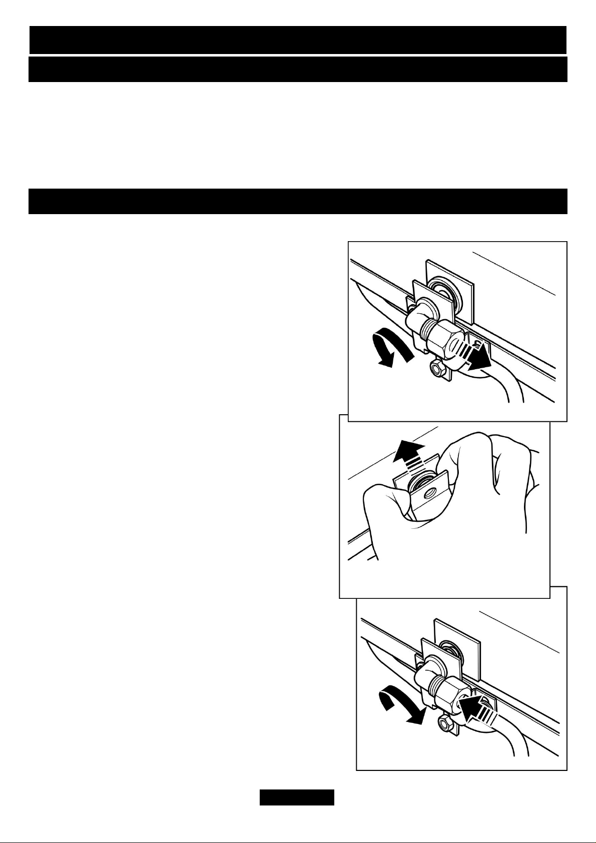
6. Support the injector elbow and unscrew the
nut connecting the pipe to the injector elbow (See
figure 1).
7. Unscrew and discard the injector elbow.
8. Remove the spring and brass insert from the
aeration plate (See figure 2).
9. Replace the spring ensuring that the wide end
sits against the aeration plate.
10. Fit the injector supplied with this kit. To do
this, screw it into place (See figure 3).
11. Support the injector elbow and connect the pipe
securing nut removed previously. Ensure that the
Figure 1.
Figure 2.
connection is tight (See figure 3).
12. Supplied with the kit are four overlay labels.
Each label reflects a different model. Pick the label
relevant to the model being converted and place this
over the appropriate area on the data label.
13. Re-connect the appliance to the gas supply and
commision the gas supply to the appliance.
Page 2
Figure 3.
Page 3

CONVERSION GUIDE
14. Check that all connections are sound using a suitable leak detection fluid.
15. Check the setting pressure. Refer to the installation and servicing manual for full
details.
16. Fit the ceramic fuel effect. Refer to the installation and servicing manual for full
details.
17. Conduct a spillage test in accordance with the installation and servicing manual.
Page 3
 Loading...