

Baxi System 100 HE Plus Installation & Servicing Instructions Manual

Installation & Servicing Instructions
Baxi System 100 HE Plus
Wall Mounted Powered Flue Condensing
Gas Fired Central Heating Boiler
Please leave these instructions with the user

Natural Gas
Baxi System 100 HE Plus
G.C.No41 075 43
Building Regulations and the Benchmark
Commissioning Checklist
Building Regulations (England & Wales) require notification of
the installation of a heating appliance to the relevant Local
Authority Building Control Department. From 1 April 2005 this
can be achieved via a Competent Persons Self Certification
Scheme as an option to notifying the Local Authority directly.
Similar arrangements will follow for Scotland and will apply in
Northern Ireland from 1 January 2006.
CORGI operate a Self Certification Scheme for gas heating
appliances.
These arrangements represent a change from the situation
whereby compliance with Building Regulations was accepted as
being demonstrated by completion of the Benchmark Logbook
(which was then left on site with the customer).
With the introduction of Self Certification Schemes, the
Benchmark Logbook is being withdrawn. However, a similar
document in the form of a commissioning checklist and service
interval record is incorporated at the back of these instructions.
Potterton is a member of the Benchmark initiative and fully
supports the aims of the programme. Its aim is to improve the
standards of installation and commissioning of central heating
systems in the UK and to encourage the regular servicing of all
central heating systems to ensure safety and efficiency.
The boiler meets the requirements of Statutory Instrument “
o
The Boiler (Efficiency) Regulations 1993 N
3083” and is
deemed to meet the requirements of Directive 92/42/EEC on
the energy efficiency requirements for new hot water boilers
fired with liquid or gaseous fuels:-
Type test for purpose of Regulation 5 certified by:
Notified Body 0087.
Product/Production certified by:
Notified Body 0086.
For GB/IE only.
Building Regulations require that installations should comply
with manufacturer's instructions. It is therefore important that
the commissioning checklist is completed by the installer. The
relevant section of Building Regulations only relates to dwellings.
Therefore the checklist only applies if the appliance is being
installed in a dwelling or some related structure.
The flowchart opposite gives guidance for installers on the
process necessary to ensure compliance with Building
Regulations.
This product has an energy rating (A) on a scale of A to G.
For more information see www.boilers.org.uk. This is a certification mark.
2
Baxi is a BS-EN ISO 9001
Accredited Company
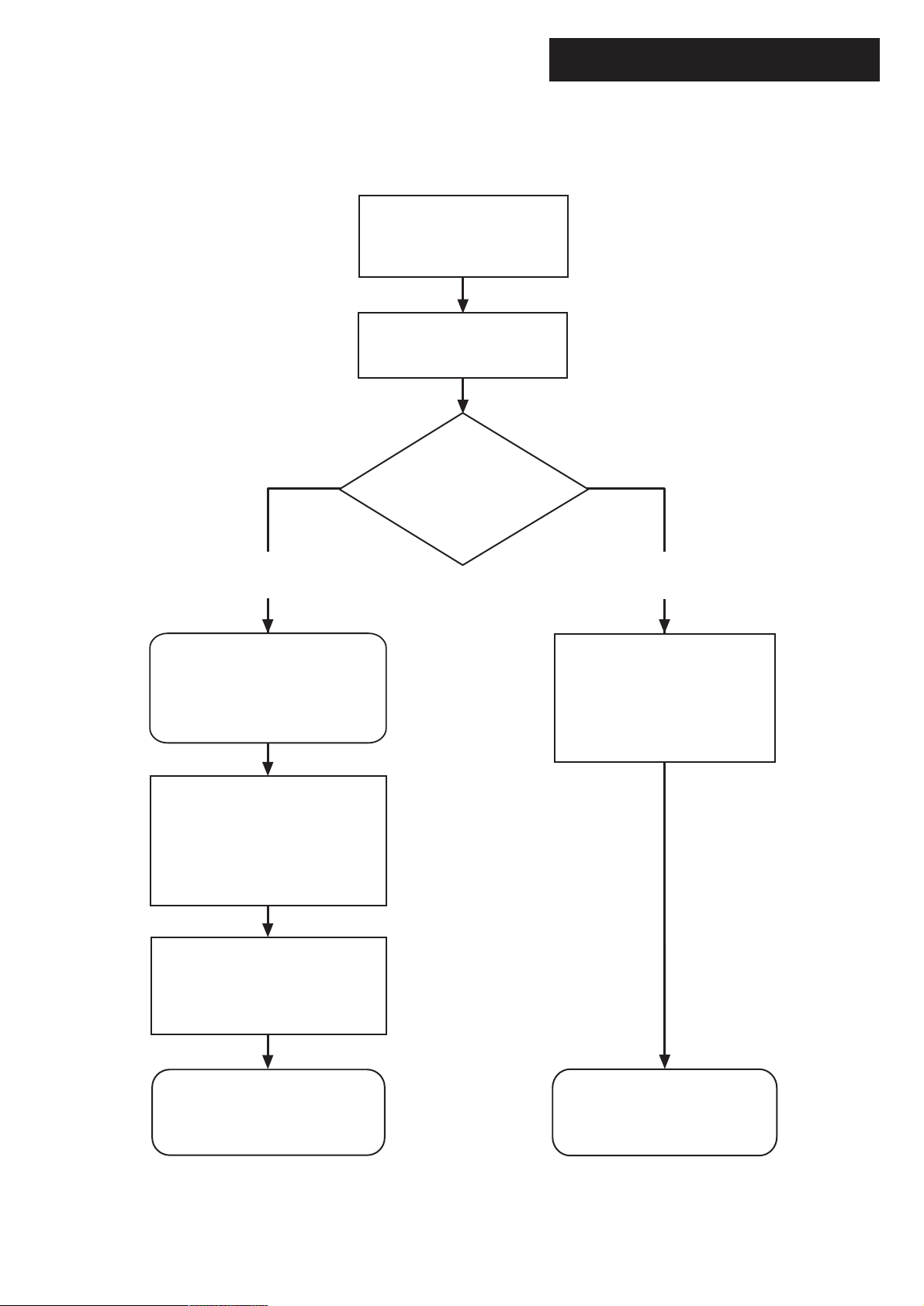
Install and Commission this
appliance to manufacturer's
instructions
Complete the
Benchmark Checklist
Choose Building
Regulations Notification
Route
Installer Notification Guidelines
Competent Person's
Self Certification Scheme
If you notify via CORGI Scheme,
CORGI will then notify the
relevant Local Authority
Building Control Scheme
on member's behalf
Scheme Members only
Call CORGI on: 0870 88 88 777
or log onto:
www.corgi-notify.com
within 10 days
You must ensure that the
notification number issued by
CORGI is writen onto the
Benchmark Checklist
Building Control
Contact your relevant Local
Authority Building Control
(LABC) who will arrange
an inspection or contact
a government approved
inspector
CORGI will record the data and
will send a certificate of
compliance to the property
LABC will record the data
and will issue a
certificate of compliance
3

Legislation
IMPORTANT - Installation, Commissioning, Service & Repair
This appliance must be installed in accordance with the manufacturer’s instructions and
the regulations in force. Read the instructions fully before installing or using the
appliance.
In GB, this must be carried out by a competent person as stated in the Gas Safety
(Installation & Use) Regulations.
Definition of competence: A person who works for a CORGI registered company and
holding current certificates in the relevant ACS modules, is deemed competent.
In IE, this must be carried out by a competent person as stated in I.S. 813 “Domestic
Gas Installations”.
Lifting - This product should be lifted and handled by two people. For recommended
hand holds see section 8.4. Stooping should be avoided and protective equipment worn
where necessary. Carrying & lifting equipment should be used as required, e.g. when
installing in a loft space.
The addition of anything that may interfere with the normal operation of the appliance
without express written permission from the manufacturer or his agent could invalidate
the appliance warranty. In GB this could also infringe the Gas Safety (Installation and
Use) Regulations.
Warning - Check the information on the data plate is compatible with local supply
conditions.
Baxi declare that no substances harmful to health are
contained in the appliance or used during appliance
manufacture.
The appliance is suitable only for installation in GB and IE and
should be installed in accordance with the rules in force, and
only used in a suitably ventilated location.
In GB, the installation must be carried out by a CORGI
Registered Installer. It must be carried out in accordance with
the relevant requirements of the:
• Gas Safety (Installation & Use) Regulations.
• The appropriate Building Regulations either The Building
Regulations, The Building Regulations (Scotland), Building
Regulations (Northern Ireland).
• The Water Fittings Regulations or Water Byelaws in
Scotland.
• The Current I.E.E. Wiring Regulations.
Where no specific instructions are given, reference should be
made to the relevant British Standard Code of Practice.
In IE, the installation must be carried out by a competent Person
and installed in accordance with the current edition of I.S. 813
‘Domestic Gas Installations’, the current Building Regulations and
reference should be made to the current ETCI rules for
electrical installation.
All systems must be thoroughly flushed and treated with
inhibitor (see section 6.2).
All CORGI registered installers carry a CORGI identification card and have a
registration number. You can check your installer is registered by telephoning
0870 4012300 or writing to:-
1 Elmwood,
Chineham Business Park,
Crockford Lane,
Basingstoke. RG24 8WG
or check online at www.corgi-gas-safety.com
Codes of Practice, most recent version should be used
In GB the following Codes of Practice apply:
Standard Scope
BS 6891 Gas Installation.
BS 5546 Installation of hot water supplies for domestic
purposes.
BS 5449 Forced circulation hot water systems.
BS 6798 Installation of gas fired hot water boilers.
BS 5440 Part 1 Flues.
BS 5440 Part 2 Ventilation.
BS 7074 Expansion vessels and ancillary equipment for
sealed water systems.
BS 7593 Treatment of water in domestic hot water
central heating systems.
In IE the following Codes of Practice apply:
Standard Scope
I.S. 813 Domestic Gas Installations.
The following BS standards give valuable additional information;
BS 5546 Installation of hot water supplies for domestic
purposes.
BS 5449 Forced circulation hot water systems.
BS 7074 Expansion vessels and ancillary equipment for
sealed water systems.
BS 7593 Treatment of water in domestic hot water
central heating systems.
4
Contents
Section Page
1.0 Introduction 6
2.0 General Layout 7
3.0 Appliance Operation 8
4.0 Technical Data 9
5.0 Dimensions and Fixings 10
6.0 System Details 11
7.0 Site Requirements 14
8.0 Installation 20
9.0 Electrical 26
10.0 Commissioning 28
11.0 Outer Case 29
12.0 Servicing 30
13.0 Changing Components 32
14.0 Short Parts List 41
15.0 Fault Finding 42
Benchmark Checklist 50
5
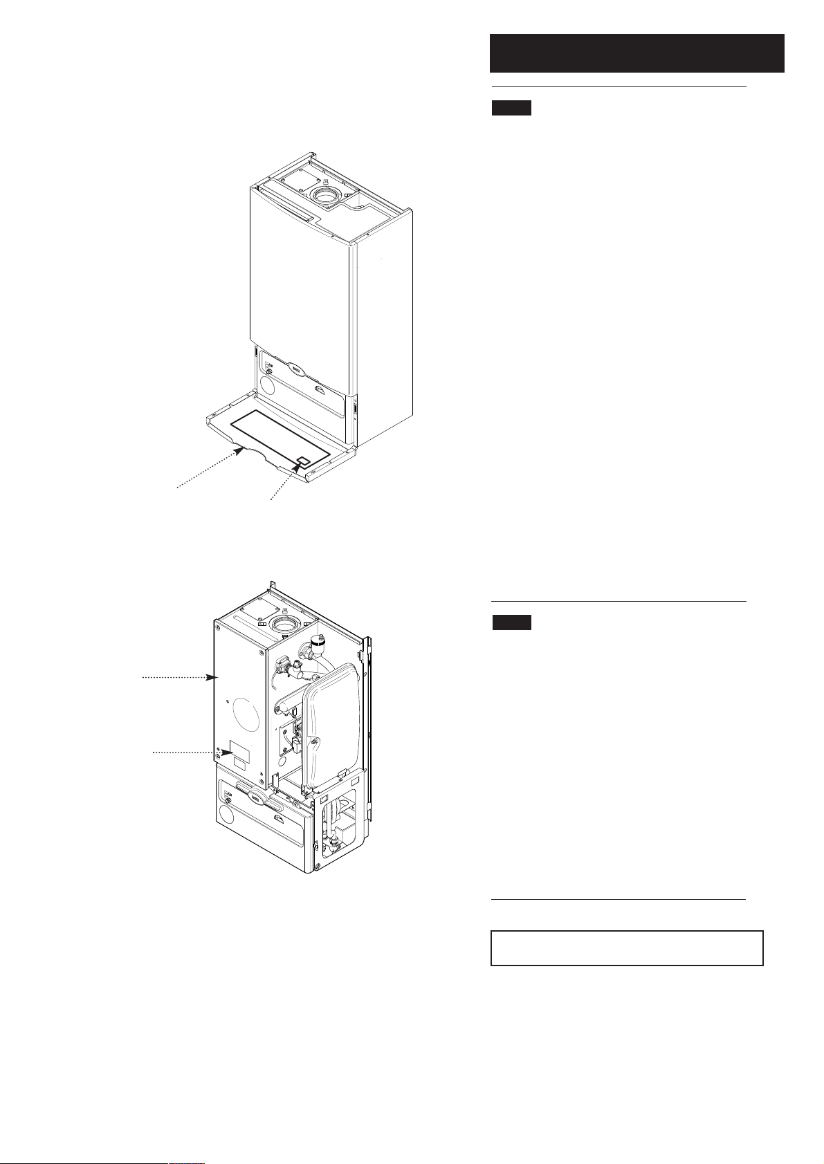
Fig. 1
Lower Door Panel
Label
1.0 Introduction
1.1 Description
1. The Baxi System 100 HE Plus is a gas fired room sealed fan
assisted condensing central heating system boiler.
2. The maximum output of the boiler is preset at 75,000
Btu/hr. The boiler will automatically adjust down to 30,000
Btu/hr according to the system load. If required, the output
can be set to 100,000 Btu/hr. Please refer to section 8.7.
3. It is designed for use on Natural Gas (G20).
4. The boiler is suitable for sealed central heating and
domestic hot water systems.
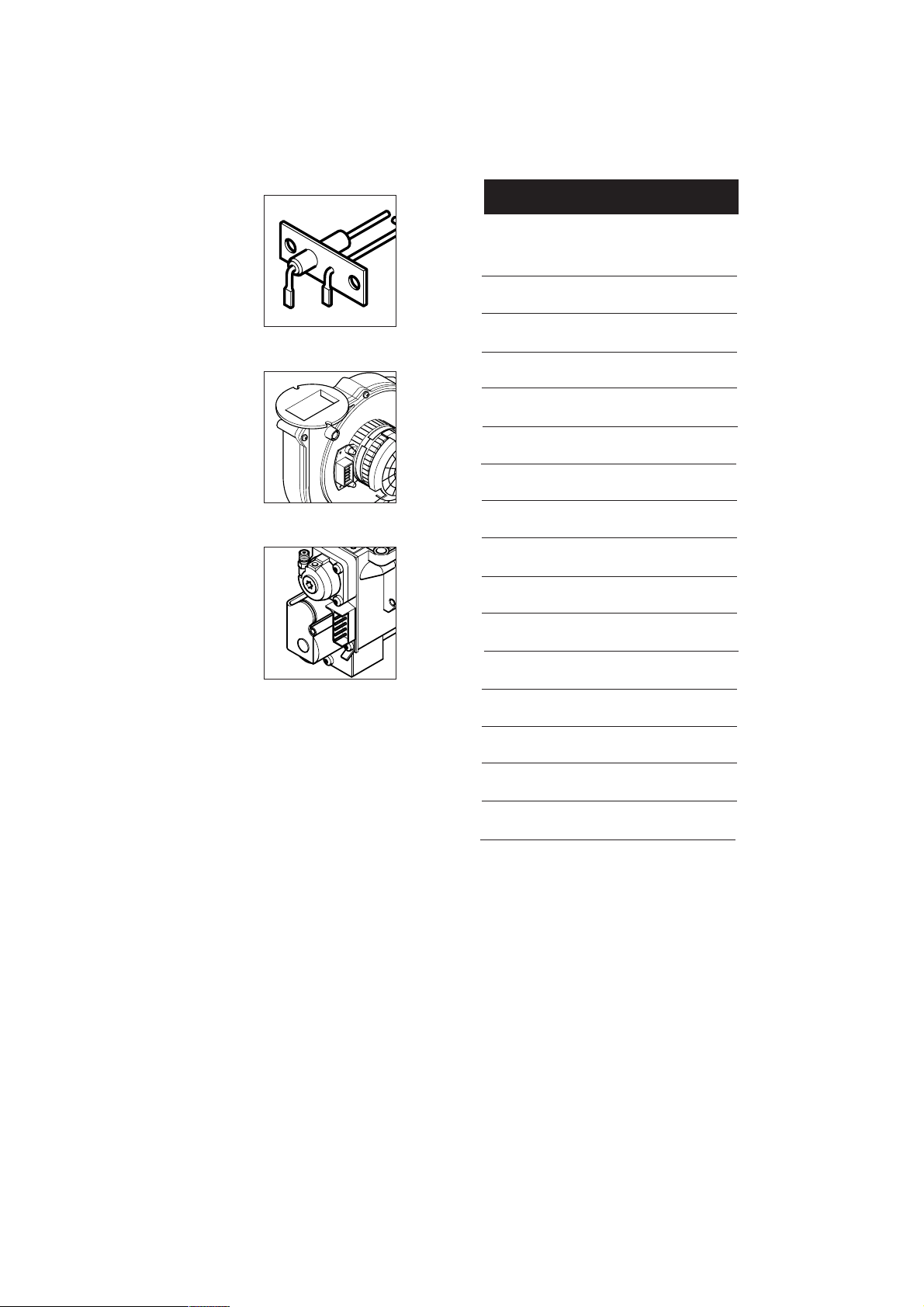
5. A label giving details of the model, serial number and Gas
Council number is situated on the rear of the lower door
panel (Fig. 1).
6. The boiler data badge is positioned on the air box door
(Fig. 2).
7. The boiler is intended to be installed in residential /
commercial / light industrial E.M.C. environments on a
governed meter supply only.
Air Box Door
Data Badge
Fig. 2
8. The boiler must be installed with one of the purpose
designed flues such as the standard horizontal flue kit, part n
236921.
1.2 Important Information
Man-made mineral fibre
• Some component parts of this appliance (insulation pads,
gaskets and rope seals) are manufactured from man-made
mineral fibre.
• Prolonged or excessive exposure to this material may
result in some irritation to the eyes, skin or respiratory tract.
• It is advisable to wear gloves when handling these items.
• Irritant dust will only be released from the items if they are
broken up or subjected to severe abrasion. In these instances
a suitable dust mask and goggles should be worn.
• Always thoroughly wash hands after installation, servicing or
changing components.
• When disposing of any items manufactured from manmade mineral fibre care must be exercised.
• If any irritation of the eyes or severe irritation of the skin is
experienced seek medical attention.
NOTE: All illustrations show the PCB Connection
Cover removed unless otherwise shown.
o
6
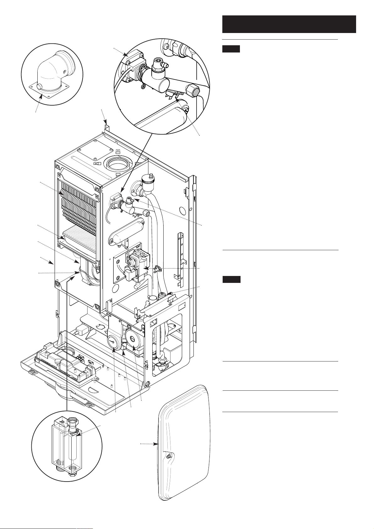
2.0 General Layout
15
2.1 Layout (Figs. 3,4 & 5)
1. Wall Plate
2. Flue Elbow
3. Heat Exchanger
4. Burner
1
Fig. 6
2
5. Air Box
6. Fan Protection Thermostat
7. Fan Assembly
Fig. 5
13/14
8. Condensate Trap
9. Gas Tap
10. Gas / Air Ratio Valve
13. Flow Temperature Safety Thermostat - Black
3
14. Flow Temperature Thermistor - Red
15. Flow Switch (dry fire protection)
16. Circulation Pump
17. Manual Air Vent
18. Pressure Relief Valve
4
6
17
19. Water Pressure Gauge
20. Expansion Vessel
5
7
10
2.2 Optional Extras
18
KIT PART N
FLUE EXTENSION KITS (110/70)
Flue Extension 0.25M 241692
Flue Extension 0.5M 241694
Flue Extension 1M
Flue Bend x 2 - 45°
Flue Bend - 90° (
Horizontal Extended Flue (1.75M) 5111457
VERTICAL FLUE (110/70)
Vertical Flue Terminal 242802
Vertical Flue Adaptor 5106888
VERTICAL FLUE (80/80)
16
9
19
Kit Boiler Connection Twin 242757
(Use two kits for 2M etc.) 241695
(Reduce overall length of flue
by 0.5m when fitting this bend)
Reduce overall length of flue
by 1m when fitting each bend)
8
o
241689
241687
Fig. 4
20
Fig. 3
7
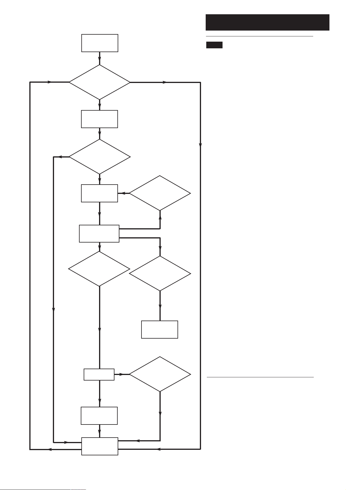
3.0 Appliance Operation
NO
Switched Live
to Boiler On.
Flow
temperature less
than set point ?
YES
10 second
Pump On.
Flow switch made ?
YES
5 second
Fan Pre-Purge.
YES
NO
Ignition done
and less than 5
attempts made ?
3.1
1. Switched Live To Boiler On: When the switched live
switches on if the flow temperature is less than the set
point then pump on occurs. When the switched live to
the boiler switches on if the flow temperature is greater
than the set point then pump overrun occurs.
2. Pump On: The pump is on while the fan, spark
generator and gas valve are off. After 10 seconds if the
flow switch has made then fan pre-purge occurs. After
10 seconds if the flow switch has not made then anti-
cycle occurs.
3. Fan Pre-Purge: The pump and fan are on while the
spark generator and gas valve are off. After 5 seconds
ignition occurs.
4. Ignition: The pump, fan, spark generator and gas
valve are on. If a flame is detected then burner on
occurs. If a flame is not detected within 5 seconds and
less than 5 ignition attempts have been made then fan
purge occurs. If a flame is not detected within 5 seconds
and 5 ignition attempts have been made then ignition
lockout occurs.
5 second
Ignition Period.
Flame Detected ?
YES
Burner On.
Ignition done and
5 attempts made ?
YES
Ignition
Lockout.
All TRVs
shut down ?
5. Burner On: The pump, fan and gas valve are on while
the spark generator is off. Flow temperature is
controlled by varying the fan speed (and thereby the
gas rate) to achieve optimum operation. If the flow
temperature is greater than the set point then pump
overrun occurs. If the TRVs all shut down then anti-
cycle occurs.
6. Pump Overrun: The pump is on while the fan, spark
generator and gas valve are off. After 1 minute anti-
cycle occurs.
7. Anti-cycle: The pump, fan, spark generator and gas
valve are off. After 3 minutes if the flow temperature is
less than the set point then pump on occurs. After 3
minutes if the flow temperature is greater than the set
point then pump overrun occurs.
8. Ignition Lockout: The pump, fan, spark generator and
gas valve are off. The boiler can only be reset by
manually using the reset button.
NO
1 minute
Pump Overrun.
3 minute
Anti-cycle.
8
YES
4.0 Technical Data
Appliance Type C
Appliance Category CAT I
C
13
2H
Heat Input Gross Max Min
kW 33.76 10.2
Btu/h 115,200 34,840
Heat Output
(Non Condensing 70° C Mean Water Temp)
Max Min
kW 30.18 9.14
Btu/h 102,980 31,180
Heat Output
(Condensing 40° C Mean Water Temp)
Max Min
kW 32.61 10.1
Btu/h 111,280 34,520
Max Gas Rate (Natural Gas)
(After 10 Mins)
Btu/hr 102,980 75,000
m3/h 2.95 2.36
ft3/h 104.2 83.3
Inlet Pressure (Natural Gas)
Min 18.1 mbar
Max 22.5 mbar
(see Section 10.1)
Injector (Natural Gas)
6.3mm Diameter
NoxClass 5
CO/CO2Ratio 0.001
33
Connections compression
Gas Supply -
1
/2” BSPF
Central Heating Flow - 22mm
Central Heating Return - 22mm
Pressure Relief Discharge - 15mm
Condensate Drain - 1” BSP
Electrical Supply 230V~ 50Hz
(Appliance must be connected to an
earthed supply)
Power Consumption 200W
External Fuse Rating 3A
Outercase Dimensions
Overall Height
Casing Height - 850mm
Casing Width - 490mm
Casing Depth - 320mm
Clearances
(For unventilated compartments see Section 7.2)
Both Sides 5mm Min
Inc Flue Elbow - 1000mm
Internal Fuse Rating (BS 4265)
Fuse 3.15 AT (PCB)
Electrical Protection IPX2
Water Content
litres 3.5
pints 6.2
Above Casing 200mm Min
Below Casing 200mm Min
Front (For Servicing) 500mm Min
Front (In Operation) 5mm Min
Expansion Vessel - (For Central Heating only.
Integral with appliance)
bar lb/in
2
Min Pre-charge Pressure 0.95 13.6
Weights kg lb
Packaged Boiler Carton 53.6 118
Packaged Flue Kit 3.6 8.0
Weight Empty 48.6 107
Installation Lift Weight 40.2 88.6
Recommended System
Temperature Drop
Condensing 20°C 36°F
Central Heating Primary
Circuit Pressures
bar lb/in
Safety Discharge 3 43.5
Max Operating 2.5 36.3
Min Operating 0.7 10.2
2
Nominal Pre-charge
Pressure 1 14.5
litre gal
Max Capacity of
CH System 125 27.5
Controls
boiler thermostat, safety thermostat,
flow switch, electronic flame sensing,
temperature protection thermostat &
condensate blockage sensor.
Horizontal
Flue Terminal Diameter 110mm
Dimensions Projection 150mm
Recommend Operating 1-2 14.5-29
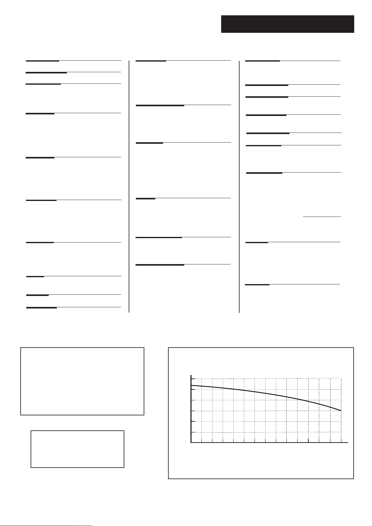
SEDBUK Declaration For
Baxi System 100 HE Plus
The seasonal efficiency (SEDBUK) is 90.9 %
This value is used in the UK Government’s Standard Assessment
Procedure (SAP) for energy rating of dwellings. The test data from
which it has been calculated have been certified by 0086.
NOTE: The maximum output of the
boiler is factory set at 22.0kW (75,000
Btu/hr). This can be altered to 30.18kW
(102,980 Btu/hr)
- see section 8.7.
Central Heating Circuit available Pump Head
600
500
400
300
Pump Head (mbar)
200
100
0
120 240 360 480
0 600 720 840
Flow Rate (l/h)
9
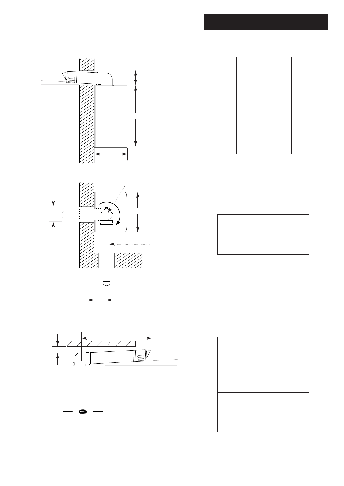
5.0 Dimensions and Fixings
DIMENSIONS
3°
(1 in 20)
E
A 850mm
B 320mm
C 490mm
A
D 125mm Ø Min.
E 150mm
F 125mm
B
360° Orientation
D
C
The 3° (1 in 20) fall provided by the
elbow is to allow condensate to run
back to the boiler, for disposal
Tube Ø 110mm
through the condensate discharge
pipe.
Fig. 7
Fig. 8
F
Y
SIDE FLUE (left and right)
X
3°
(1 in 20)
For every 1m of horizontal flue
length, the clearance above the top
of the flue elbow should be 55mm to
incorporate the 3°
(1 in 20) fall in the flue from the
terminal to the elbow.
Flue length (Y)
up to 1m
1m - 2m
2m - 3m
Clearance (X)
55mm
110mm
165mm
10
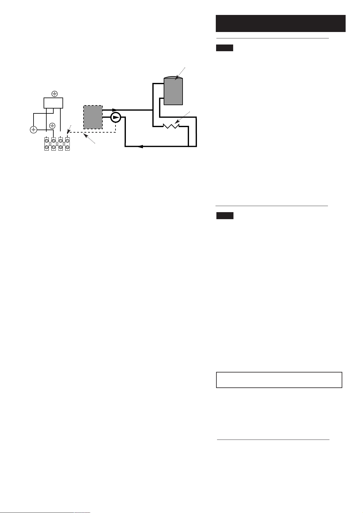
6.0 System Details
6.1 Water Circulating Systems
Switch live from
programmer, etc.
N
S/L
Filter
Optional
Pump
N
S/L
Boiler
Connections
Fig. A Wiring an extra pump to the pump feed
connection of boiler
Boiler
Feed
Live feed to
pump
Hot water
Central
heating
load
1. The appliance is suitable for fully pumped sealed systems
only.
The following conditions should be observed on all systems:
• The boiler must not be used with a direct cylinder.
• Drain cocks should be fitted to all system low points.
• All gas and water pipes and electrical wiring must be installed
in a way which would not restrict the servicing of the boiler.
• Air vents should be fitted to all system high points.
• An air rejection separator is recommended to ensure correct
operation of all appliance components.
2. If the system requires an output from the boiler greater than
75,000 Btu/hr then an additional external pump will need to be
fitted.
3. If the system is fully TRV’d with no bypass then any external
pump can be wired back to the boiler Optional Pump Feed
connection. This will protect the pump by turning it off if all the
TRVs are shut (sensed by the boiler flow switch). This is wired
as in Fig. A. See section 8.7 for how to increase boiler output
from 75.000 Btu/hr to 100,000 Btu/hr.
6.2 Treatment of Water Circulating Systems
• All recirculatory water systems will be subject to corrosion
unless an appropriate water treatment is applied. This means that
the efficiency of the system will deteriorate as corrosion sludge
accumulates within the system, risking damage to pump and valves,
boiler noise and circulation problems.
• When upgrading existing systems that exhibit evidence of
sludging, it is advisable to clean the system prior to treatment in
order to remove any sludge and reduce the likelihood of these
deposits damaging new components.
• When fitting new systems flux will be evident within the system,
which can lead to damage of system components.
• All systems must be thoroughly drained and flushed out. The
recommended flushing and cleansing agents are Betz-Dearborn
Sentinel X300 or X400 and Fernox Superfloc Universal Cleanser
which should be used following the flushing agent manufacturer’s
instructions.
• System additives - corrosion inhibitors and flushing
agents/descalers should be suitable for aluminium and comply to
BS7593 requirements. The only system additives recommended
are Betz-Dearborn Sentinel X100 and Fernox-Copal which should
be used following the inhibitor manufacturer’s instructions.
Failure to flush and add inhibitor to the system will invalidate
the appliance warranty.
• It is important to check the inhibitor concentration after
installation, system modification and at every service in accordance
with the manufacturer’s instructions. (Test kits are available from
inhibitor stockists.)
• For information or advice regarding any of the above contact the
Baxi Helpline.
11
Timer
CH on
HW on
HW off
L
N
230V
50Hz
L NE
g/y
Room
Stat
b
w
Cylinder
Stat
1
C2
Y Plan
Diverter
Valve
gr
o
Key to colours
b - Blue
br - Brown
w - White
o - Orange
gr - Grey
g/y - Green/Yellow
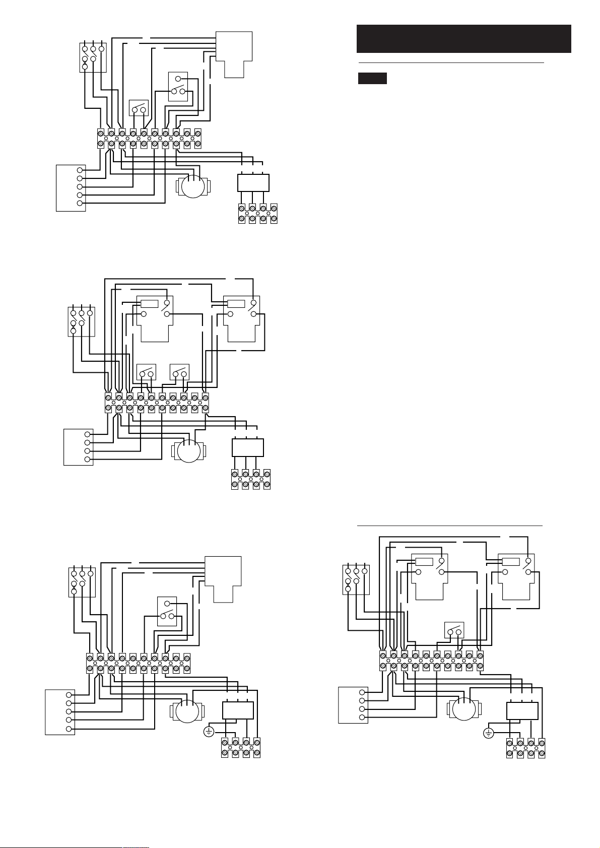
6.0 System Details
6.3 System Controls
This boiler does not require a bypass.
This boiler does not require a permanent live.
An additional external pump is required if a boiler
output of greater than 75,000 Btu/hr is required.
The additional external pump only needs wiring directly
to the boiler for fully TRV’d systems.
1. To comply with Part L1 of the Building Regulations the
heating system into which the boiler is installed should
include the following:
Pump
L
E
N
LNE
Electrical
Filter
Y Plan, Room Thermostat System, CH Interlocked By Room Thermostat
At least the Radiator(s) near the Room Thermostat not TRV’d
Pump run from Switched Live
By-pass permitted but not required for Part L1 compliance
230V
50Hz
L NE
gr
Motor
b
S Plan
br
Valve
g/y
Room
Stat
b
Cylinder
Stat
gr
Motor
br
o
S Plan
g/y
Valve
o
Timer
L
E
N
Electrical
Filter
CH on
HW on
L
N
LNE
Pump
S Plan, Room Thermostat System, CH Interlocked By Room Thermostat
At least the Radiator(s) near the Room Thermostat not TRV’d
Pump run from Switched Live
By-pass permitted but not required for Part L1 compliance
230V
50Hz
L NE
b
g/y
w
Cylinder
Stat
1
C2
Y Plan
Diverter
Valve
gr
o
a) zone controls
b) timing controls
c) boiler control interlocks
2. Such a system needs to be fully pumped and must
provide independent temperature and time control to
both the heating and hot water circuits and have a boiler
interlock.
3. The boiler should be controlled so that it operates on
demand only. Where it is proposed to effect control by
thermostatic radiator valves, a room thermostat (or
other device such as a flow switch - a flow switch is
integral to this boiler) should also be provided to switch
off the boiler when there is no demand for heating or hot
water.
4. The interlock for the CH circuit can be provided by
either a Room Thermostat or by a fully TRV’d system
without a bypass. If an external pump is required and the
boiler flow switch is being used as the system interlock
then the additional pump will need to be wired back to
the boiler optional pump feed connection. Connection
diagrams for both options for Y and S plan systems are
shown.
230V
50Hz
L NE
gr
Motor
b
b
S Plan
Valve
g/y
br
Cylinder
gr
Motor
br
o
S Plan
g/y
Valve
o
Stat
Timer
CH on
HW on
HW off
L
N
LNE
Pump
L
E
N
Filter
Optional
Pump Feed
Y Plan, Fully TRV’d System, CH Interlocked By Boiler Flow Switch
Room Thermostat should not be fitted
Pump must be run from Boiler Optional Pump Feed connection for Part L1 compliance
By-pass not permitted (must be valved off) for Part L1 compliance
12
Timer
CH on
HW on
L
N
LNE
Pump
L
E
Electrical
Filter
N
Optional
Pump Feed
S Plan, Fully TRV’d System, CH Interlocked By Boiler Flow Switch
Room Thermostat should not be fitted
Pump must be run from Boiler Optional Pump Feed connection for Part L1 compliance
By-pass not permitted (must be valved off) for Part L1 compliance
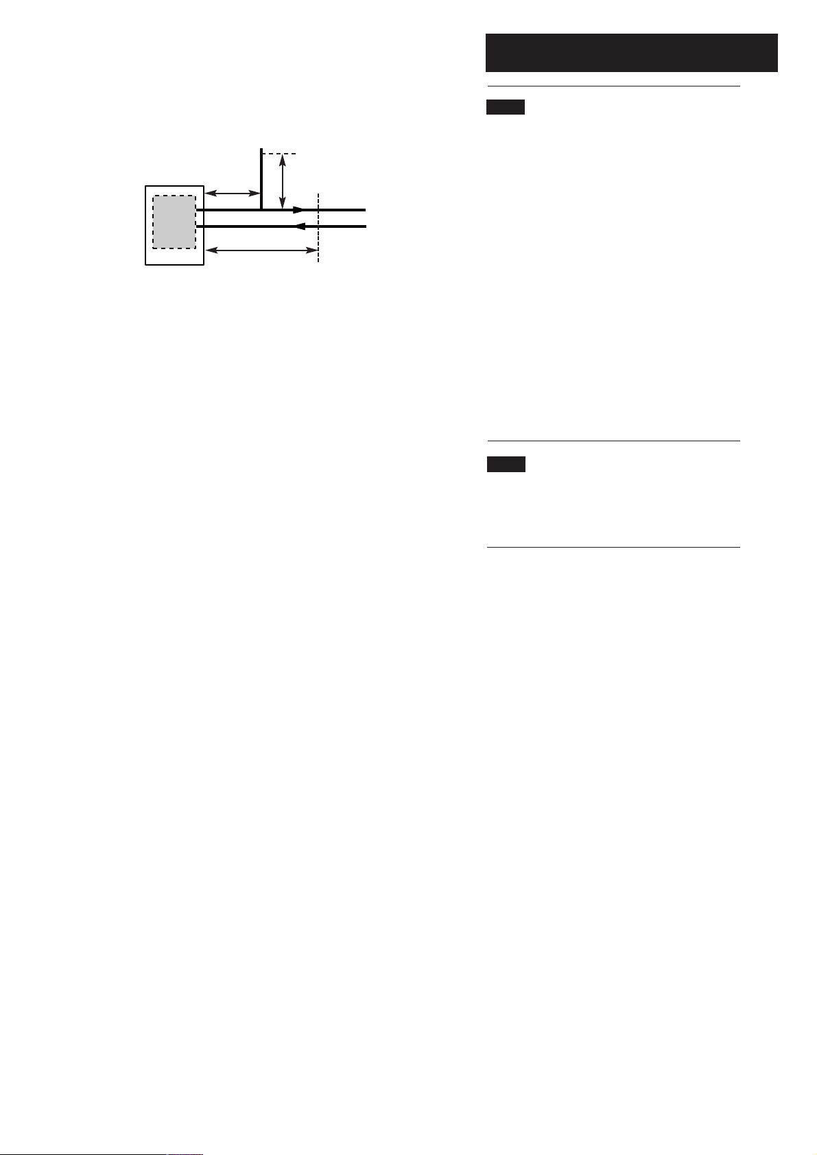
Fig. 9
Boiler
Copper
0.5m
Copper
1m
Copper
0.5m
Flow
Return
6.0 System Details
6.4 Pipework
1. The sizes of flow and return pipes from the boiler should
be determined by normal methods, according to the
requirements of the system. The connection to the boiler is
22mm compression fitting.
2. Due to space requirements at the rear of the tap bracket,
pipework should comprise of solder fittings.
3. A 20 °C (36°F) drop in temperature across the system is
recommended for condensing boilers. Existing radiators may
be oversized and so allow this, but where radiator sizing is
marginal it may be advisable to retain a system temperature
drop of 11°C (20°F).
4. In systems using non-metallic pipework it is necessary to
use copper pipe for the boiler Flow and Return. The copper
must extend at least 1 metre from the boiler and include any
branches (Fig. 9).
6.5 Thermal Stores
1. When the Baxi System 100 HE Plus is fitted in
conjunction with a thermal store, both jumpers must be
removed from the Control PCB, see Fig. 34 Section 8.7.
13

6.0 System Details
Cold
Mains
Fig. 10
Expansion Vessel
removed for clarity
Stop
Valve
Double
Check
Valve
Temporary
Hose
Stop
Valve
CH
Return
6.6 System Filling and Pressurising
(Fig. 10)
1. A filling point connection on the central heating return
pipework must be provided to facilitate initial filling and
pressurising and also any subsequent water loss
replacement/refilling.
2. The filling method adopted must be in accordance
with the Water Supply (Water Fittings) regulations and
the Water Bylaws (Scotland).
3. Your attention is drawn to, for GB: Guidance G24.2
and recommendation R24.2 of the Water Regulations
Guide. for IE: the current edition of I.S. 813 “Domestic
Gas Installations”.
4. The sealed primary circuits may be filled or
replenished by means of a temporary connection
between the primary circuit and a supply pipe provided
the arrangement in accordance with Diagram R24.2a of
the Water Regulations Guide.
5. The temporary hose must be completely removed at
both ends after use.
Fig. 11
Expansion Vessel
Pressure Relief
Valve
6.7 Expansion Vessel (Fig. 11)
1. The appliance expansion vessel is pre-charged to 1
2
bar (10 lb/in
). Therefore, the minimum cold fill pressure
is 1 bar. The vessel is suitable for correct operation for
system capacities up to 125 litres (27.5 gal). For greater
system capacities an additional expansion vessel must be
fitted - refer to BS 7074 Pt 1.
6.8 Pressure Relief Valve (Fig. 11)
1. The pressure relief valve is set at 3 bar, therefore all
pipework, fittings, etc. should be suitable for pressures in
excess of 3 bar.
2. The pressure relief discharge pipe should be not less
than 15mm dia, run continuously downward, and
discharge outside the building, preferably over a drain. It
should be routed in such a manner that no hazard
occurs to occupants or causes damage to wiring or
electrical components. The end of the pipe should
terminate facing down and towards the wall.
3. The discharge must not be above a window, entrance
or other public access. Consideration must be given to
the possibility that boiling water/steam could discharge
from the pipe.
14
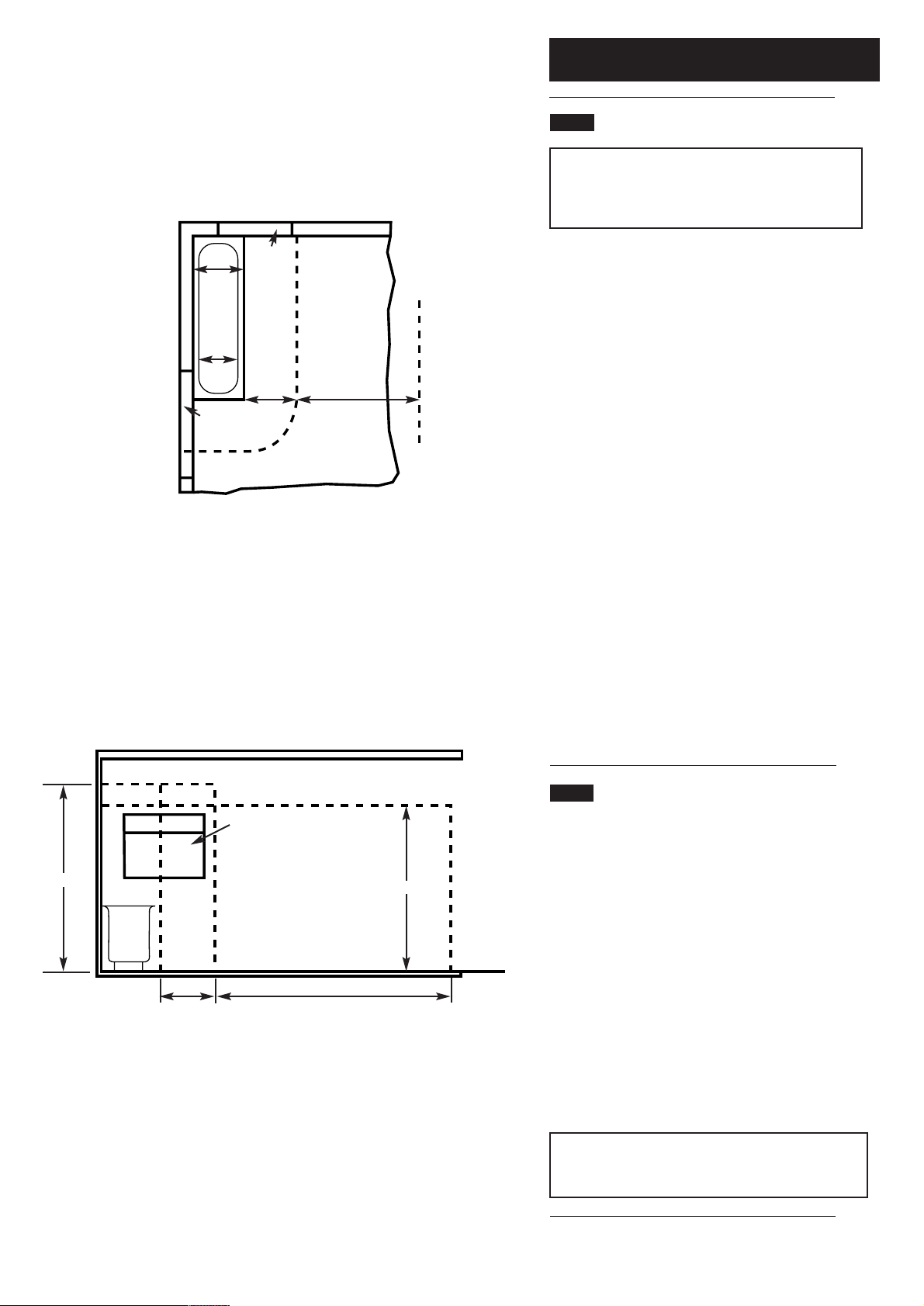
Fig. A
Zone 2
Zone 1
Zone 0
Window
Recess
Zone 2
In GB Only
Window
Recess
Zone 2
0.6 m
Zone 3
Zone 3
2.4 m
7.0 Site Requirements
7.1 Location
NOTE: Due to the high efficiency of the boiler a plume
of water vapour will be discharged from the flue. This
should be taken into account when siting the flue
terminal.
1. The boiler may be fitted to any suitable wall with the flue
passing through an outside wall or roof and discharging to
atmosphere in a position permitting satisfactory removal of
combustion products and providing an adequate air supply.
The boiler should be fitted within the building unless
otherwise protected by a suitable enclosure i.e. garage or
outhouse. (The boiler may be fitted inside a cupboard - see
Section 7.2).
2. If the boiler is sited in an unheated enclosure then it is
recommended to incorporate in the system controls a
suitable device for frost protection.
3. If the boiler is fitted in a room containing a bath or shower,
it can only be fitted in zone 3, (Figs. A & B shows zone
dimensions for a bathtub. For other examples refer to
Section 601 of the Current I.E.E. Wiring Regulations)
reference must be made to the relevant requirements.
In GB this is the current I.E.E. Wiring Regulations and Building
Regulations.
In IE reference should be made to the current edition of I.S.
813 “Domestic Gas Installations” and the current ETCI rules.
3.0 m
Zone 2
Zone 1
Zone 0
Fig. B
Zone 3
Zone 2
0.6 m
Window
Recess
Zone 2
In GB Only
Outside Zones
Zone 3
2.4 m
2.25 m
Ceiling
Outside
Zones
4. If the boiler is to be fitted into a building of timber frame
construction then reference must be made to the current
edition of Institute of Gas Engineers Publication IGE/UP/7
(Gas Installations in Timber Framed Housing).
7.2 Ventilation of Compartments
1. Where the boiler is installed in a cupboard or
compartment, no air vents are required for cooling purposes
providing that the minimum dimensions below are
maintained.
Sides 25mm
Top 200mm
Bottom 200mm
Front 100mm
2. If the boiler is installed in a smaller cupboard or
compartment it must be ventilated according to
BS 5440 Part 2 and the minimum clearances given in section
4.0 “Technical Data” maintained.
3. Any compartment should be large enough to house the
boiler only.
NOTE: The ventilation label on the front of the outer case
MUST NOT BE REMOVED when the appliance is installed
in a compartment or cupboard.
15

7.0 Site Requirements
5mm Min
490mm
5mm Min
200mm
850mm
200mm
7.3 Clearances (Figs. 13 &14)
1. A flat vertical area is required for the installation of the
boiler.
2. These dimensions include the necessary clearances around
the boiler for case removal, spanner access and air
movement. Additional clearances may be required for the
passage of pipes around local obstructions such as joists
running parallel to the front face of the boiler.
3. For unventilated compartments see Section 7.2.
7.4 Gas Supply
1. The gas installation should be in accordance with the
relevant standards. In GB this is BS 6891. In IE this is the
current edition of I.S. 813 “Domestic Gas Installations”.
2. The connection to the appliance is
1
/2” BSPF.
3. Ensure that the pipework from the meter to the appliance
is of adequate size. (22mm recommended at the appliance).
Do not use pipes of a smaller diameter than 22mm up to
the boiler connection.
Fig. 13
500mm
For Servicing
Purposes
3°
(1 in 20)
7.5 Electrical Supply
1. External wiring must be correctly earthed, polarised and in
accordance with relevant regulations/rules. In GB this is the
current I.E.E. Wiring Regulations. In IE reference should be
made to the current edition of ETCI rules.
2. The mains supply is 230V ~ 50Hz fused at 3A.
NOTE: The method of connection to the electricity
supply must facilitate complete electrical isolation of the
appliance. Connection may be via a fused double-pole
isolator with a contact separation of at least 3mm in all
poles and servicing the boiler and system controls only.
WARNING: The PCB Control and Fan
Assembly is 325 Vdc. Isolate at supply before
access.
16
Fig. 14
5mm
In Operation
320mm
 Loading...