

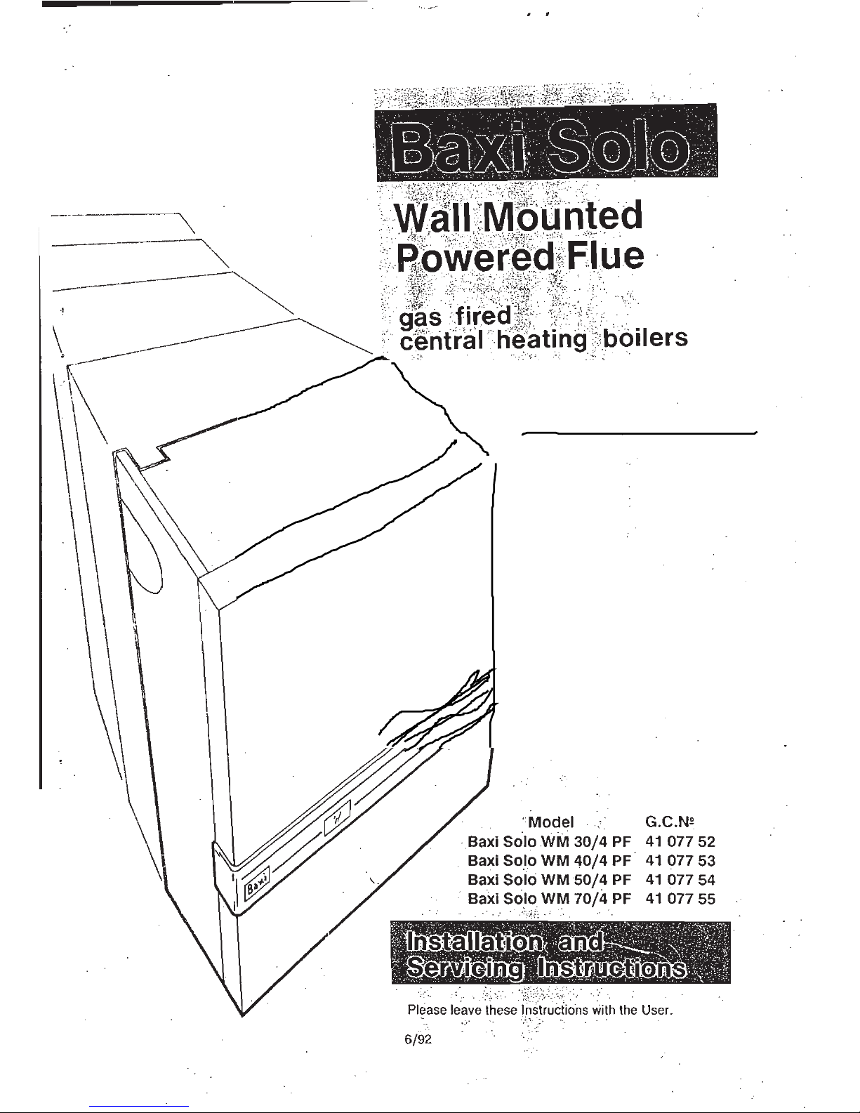
Baxi Solo WM 30/4 PF, Solo WM 50/4 PF, Solo WM 70/4 PF, Solo WM 40/4 PF User Manual
BS 5258BS 6332
Safety & Performance
Baxi heating is one of the leading manufacturers of
.tdomestic heating products in the U.K
Our first priority is to give a high quality service to
our customers. Quality is built into every Baxi
, product - products which fulfil the demands
and needs of modern consumers, offering
choice, efficiency and reliability.
To keep ahead of changing trends, we have
made a commitment to develop new ideas using
the latest technology - with the aim to continue
making the products that customers want to buy.
Baxi is also the largest manufacturing partnership
•
in the country. Everyone who works at the
company has a commitment to quality because, as
•
shareholders, we know that satisfied customers
- mean continued success.
We hope you get a satisfactory service from
Baxi. If not, please let us know.
BS 5750 Company
1:91.(e-
CONTENTS
Introduction
Technical Data
System Details
Site Requirements
Installation
Water Circulation Systems
Pipework
System Controls
Low Head Installation
Sealed Systems
Location
Clearances
Flue Position
Rue Dimensions
Ventilation
of
Compartments
Gas Supply
Electrical Supply
Initial PreparationPreparation
Rear Flue
Flue Preparation
Assembly
of
Flue
Fitting the Back Plate
Left or Right Flue
Flue Preparation
Assembly
of
Flue
Fitting the Back Plate
Terminal Guard
Fining a Terminal Guard
Internal Fitting Kit
Electrical Connections
Fining the Combustion Box
Water Connections
Pipe Routes
Gas Connection
Commissioning the Appliance
Fitting the Outer Case
Overheat Cut-Off Device
Annual Servicing
Changing Components
^<1-t..
4
1;14
g ,-trreiirgsivircitalemtro
Cleaning the Combustion Box
Cleaning the Burner/Injector
Cleaning the Pilot
AIEBEEIZZIEZZE
Pilot Injector
Ignition Electrode
Fan
Pressure Switch
Boiler Thermostat
Control Board/Electrode Lead
Overheat Thermostat
Insulation Panel Door
Burner and Injector
Insulation Panel Combustion Box
Gas Valve
Fault Finding
Short Parts List
7
,1
4
‘
z
le
4--I.W.7:41-
4
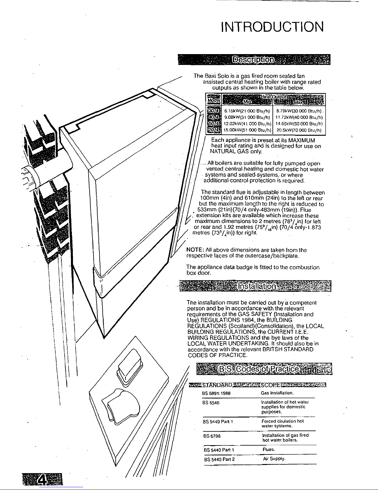
INTRODUCTION
The Baxi Solo is a gas fired room sealed fan
assisted central heating boiler with range rated
outputs as shown in the table below.
L
.:.:7.,
.i:1,3saTtlir
^g"?.M
-;-..-1•.•,,a
• -
..
i,
,
..
VA
r.,..?,15::41]lfrrii.;.;.,:).,t1.,
6.15kW(21 000 Btu/h)
8 79kW(30 000 Btu/h)
-:
II
0
9.08kW(31 000 Btu/h)
11.72kW(40 000 Btu/h)
..ca-
.
12.02kW(41 000 Btu/h)
14.65kW(50 000 Btu/h)
15.00kW(51 000 Btu/h)
20.5kW(70 000 Btu/h)
Each appliance is prese at its MAXIMUM
hea input rating and is designed for use on
NATURAL GAS only.
...AB boilers are suitable for fully pumped open
vented central heating and domestic hot water
•
systems and sealed, systems, or where
additional control protection
is
required.
The standard flue is adjustable in length between
100mm (4in) and 610mm (24in) to the left or rear
but the maximum length to the right is reduced to
533mm (21in)(70/4 only-483mm (19in)). Flue
extension kits are available which increase these
maximum dimensions to 2 metres (78
3/4
in) for left
or rear and 1.92 metres (759/16in) (70/4 only-1.873
metres (733/4in)) for right.
NOTE: All above dimensions are taken from the
respective faces of the outercase/backplate.
The appliance data badge is fitted to the combustion
box door.
:Inpitallation;
.4 • A,
The installation must be carried out by a competent
person and be in accordance with the relevant
requirements of the GAS SAFETY (Installation and
Use) REGULATIONS 1984, the BUILDING
REGULATIONS (Scotland)(Consolidation), the LOCAL
BUILDING REGULATIONS, the CURRENT I.E.E.
WIRING REGULATIONS and the bye laws of the
LOCAL WATER UNDERTAKING. It should also be in
accordance with the relevant BRITSH STANDARD
CODES OF PRACTICE.
13;Sfiebeles,of,Praadtid:e
STANDARDaSCOPai
85 6891:1988
Gas Installation.
BS 5546
Installation of hot water
supplies for domestic
purposes.
88 5449 Part 1
Forced cirulation hot
water systems.
BS 6798
Installation of gas fired
hot water boilers.
BS 5440 Part 1
Rues.
855440 Part 2
Air Supply.
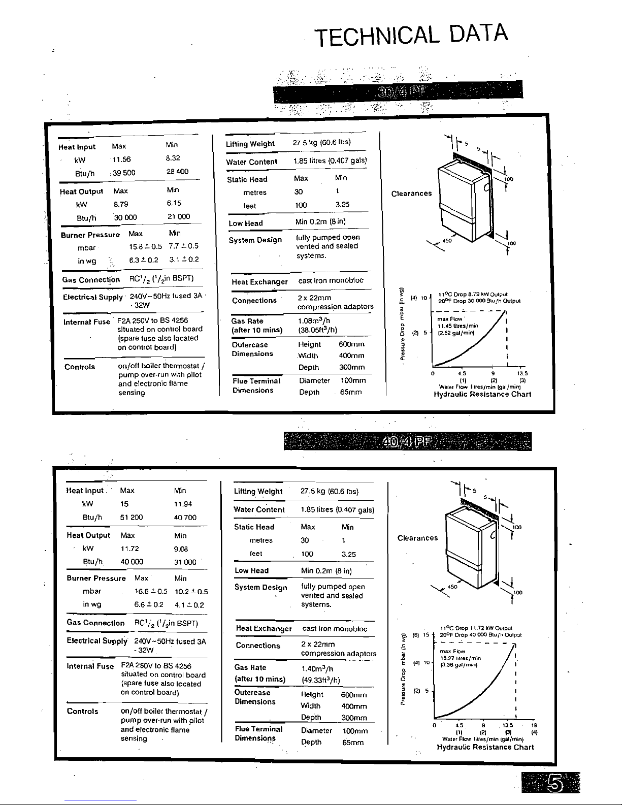
Internal Fuse
F2A 250V to BS 4256
situated on control board
(spare fuse also located
on control board)
Connections
2 x 22mm
compression adaptors
Gas Rate
(after 10 mins)
Outerease
Dimensions
1.08m3/h
(38.05113/h)
Height600mm
Width
400mm
Depth
300mm
Flue Terminal
Dimensions
Diameter 100mm
Depth
65mm
Heat Input
Max
Min
Lifting Weight
•
kW
11.56
8.32
Water Content
Btu/h
39500
28 400
Static Head
Heat Output
Max
Min
metres
kW
8.79
6.15
feet
Btuth
SO 000
21 000
Low Head
Burner Pressure
Max
Min
System Design
mbar
15.8±0.5
7.7 ±0.5
in wg
6.3
=
0.2
3.1 =0.2
Gas Connection
RC72
('/in BSPT)
Electrical Supply 240V-50H2 fused 3A
- 32W
Controls
on/off boiler thermostat /
pump over-run with pilot
and electronic flame
sensing
Heat Exchanger cast iron monobloc
I 1
0
C Drop 8.79 kW Output
c
rn-
(4)
ID
20°F Drop 30 000 131u/h Output
max Flow
11.45 litres/mm
2
(2) 5
12.52 gal/min)
C.
o
4.5
9
13.5
(1)
RI
131
Water Flow litres/mm
n (gal/min)
Hydraulic Resistance Chart
27.5 kg (60.6 lbs)
1.85 litres (0.407 gals)
Max
Min
30
1
100
3.25
Min 0.2m (8 in)
fully pumped open
vented and sealed
systems.
Max
15
51 200
Min
11.94
40 700
Heat Input
kW
Btu/h
Max
11.72
40 000
Min
9.08
31 000
Heat Output
kW
Btu/h
Min
10.2 =0.5
4.10.2
Burner Pressure Max
mbar
.
16.6 ± 0.6
in wg
6.6 0.2
Internal Fuse
F2A 250V to BS
4256
situated
on control board
(spare fuse also located
on control board)
Gas Connection
RC'/2 (I/
2
in BSPT)
Electrical Supply 240V-50Hz fused 3A
- 32W
Controls on/off boiler thermostat /
pump over-run with pilot
and electronic flame
sensing
•
Connections
Gas Rate
(after
10
mins)
Flue Terminal
Dimensions
2 x 22mm
compression
1.40m3/h
(49.33t13/h)
Height
Width
Depth
Diameter
Depth
adaptors
-1
max Flow
a
(4)
10
15.27 Mres/rnin
(3.36 gal/min)
2
0
600mm
(2)
5
400mm
300mm
o4.59
13.5
•
18
.
.
100mm
(1)
(2)
PI
(4)
65mm
Water Flow litres/min tgailmin)
Hydraulic Resistance Chart
-
Outerease
Dimensions
Lifting Weight
27.5 kg (60.6 lbs)
Water Content1.85 litres (0.407 gals)
Static Head
Max
Min
metres
30
1
Clearances
feet
100
3.25
System Design
fully pumped open
vented and sealed
systems.
X50
Heat Exchanger cast iron monobloc
11
0
0 Drop 11.72 kW Output
ggoc Drop 40 000 BW/h Output
rth (6) 15
Low Head
MM 0.2m (8 in)
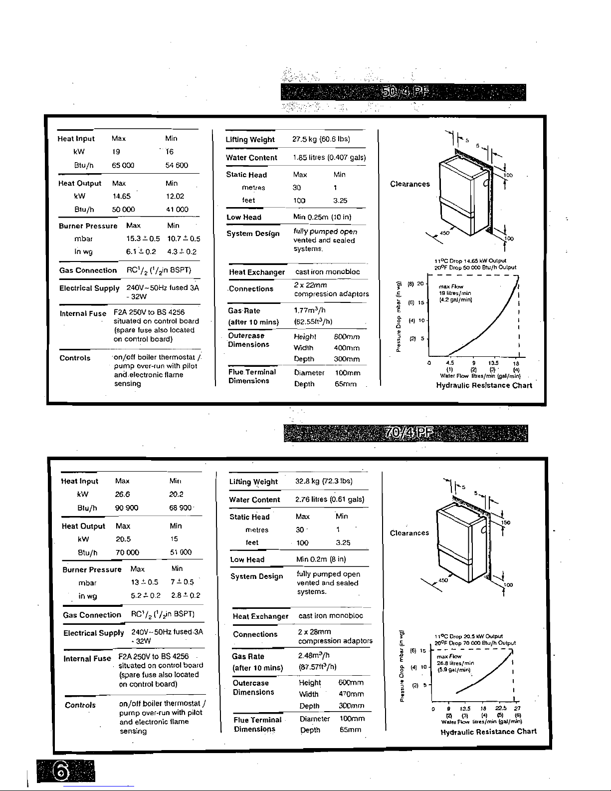
TECHNICAL DATA
P9):V4
(4)
10
(2) 5
Lifting Weight
27.5 kg (60.6 lbs)
Water Content
1.85 litres (0.407 gals)
Static Head
metres
MM 0.25m (10 in)
fully pumped open
vented and sealed
systems.
Heat Exchanger cast iron monobloc
2
x
22mm
compression adaptors
1.77m3/h
(62.5583/h)
Height600mm
Width
400mm
Depth300mm
Flue Terminal
Diameter 100mm
Dimensions
Depth
65mm
Clearances
11
0
0 Drop 14.65 kW Output
20°F Drop 50 CO0 Btuth Output
max
Flow
19 litres/min
(4.2 gal/min)
04.5
913.518
(1)
(2)(3)(4)
Water Flow litres/min (gal/mln)
Hydraulic Resistance Chart
Max
30
Min
1
Low Head
System Design
Connections
Gas Rate
(after
10
mins)
Outercase
Dimensions
feet
100
3.25
Max
26.6
90 900
Min
20.2
68 900:
Heat Input
kW
Btu/h
Lifting Weight
32.8 kg (72.3 lbs)
MM 0.2m (8 in)
Low Head
Diameter
Depth
Flue Terminal
Dimensions
Internal Fuse
F2A 250V to BS 4256
situated on control board
(spare fuse also located
on control board)
Controls
on/off boiler thermostat /
pump over-run with pilot
and electronic flame
sensing
Height
Width
Depth
600mm
470mm
300mm
100mm
65mm
Static Head
Max
Min
Max
Min
Heat Output
kW
Blu/h
metres
30
1
Clearances
20.5
15
feet
100
3.25
70 000
51 000
Burner Pressure
mbar
in wg
Max
13 = 0.5
5.2 = 0.2
Min
7-±a5 •
2.8 = 0.2
System Design
fully pumped open
vented and sealed
systems.
Gas Connection RC
1
/
2
('/
2
in BSPT)
Electrical Supply 240V-50Hz fused 3A
- 32W
2 x 28mm
compression adaptors
2.48m3/h
(87.5783/h)
11°C Drop 20.5 kW Output
20°F Drop 70 000 Btu/h Output
r,
(6) l5
a
(4) 10-
0
(2) 5 -
max Flow
26.8 litres/min
(5.9 gal/min),
1
0
9 13.5
18
22.5 27
(2)(3)
99(5)
(8)
Water Flow litres/min (gal/min)
Hydraulic Resistance Chart
Water Content
2.76 litres (0.61 gals)
Heat Exchanger cast iron monobloc
Connections
Gas Rate
(after 10 mins)
Outercase
Dimensions
Heat Input
Max
Min
kW
19
Btu/h
65 000
54 600
Heat Output Max
Min
kW
14E5
12.02
Btu/h50 000
41 000
Burner Pressure Max
Min
mbar
15.3 = 0.5 107
in wg
6.1 = 0.2 4.3 = 0.2
Gas Connection RC'/2 (
I
/2in BSPT)
Electrical Supply 240V-50Hz fused 3A
- 32W
Internal Fuse F2A 250V to BS 4256
situated on control board
(spare fuse also located
on control board)
Controls on/off boiler thermostat /
pump over-run with pilot
and electronic flame
sensing
k
fk
te
i
t
i
r
treS6Y9N
t
System Drains at
All Low Points
15mm By-pass
if required
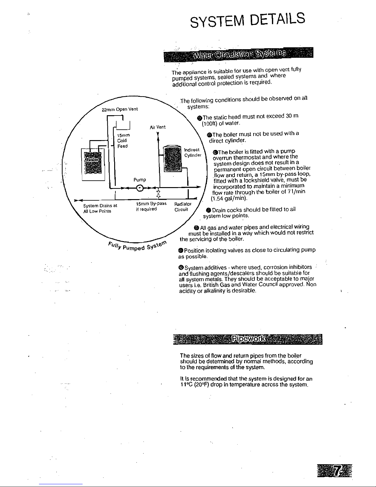
SYSTEM DETAILS
The appliance is suitable for use with open vent fully
pumped systems, sealed systems and where
additional control protection is required.
•
The following conditions should be observed on all
systems:
()The static head must not exceed 30 m
(100ft) of water.
•The boiler must not be used with a
direct cylinder.
0The boiler is fitted with a pump
overrun thermostat and where the
system design does not result in a
permanent open circuit between boiler
flow and return, a 15mm by-pass loop,
fitted with a lockshield valve, must be
incorporated to maintain a minimum
flow rate through the boiler of
7
1/min
(1.54 gal/min).
•
Drain cocks should be fitted to all
system low points.
Ptp,
cteta
"Y
Pumped SI-
OPosition isolating valves as close to circulating pump
as possible.
S
System additives - where used, corrosion inhibitors
and flushing agents/descalers should be suitable for
all system metals. They should be acceptable to major
users i.e. British Gas and Water Council approved. Non
acidity or alkalinity is desirable.
The sizes of flow and return pipes from the boiler
should be determined by normal methods, according
to the requirements of the system.
It Is recommended that the system is designed for an
11°C (20°F) drop in temperature across the system.
22mm Open Vent
15mm
Cold
Feed
Air Vent
-gt
Radiator
Circuit
0 All gas and water pipes and electrical wiring
must be installed in a way which would not restrict
the servicing of the boiler.
Indirect
Cylinder
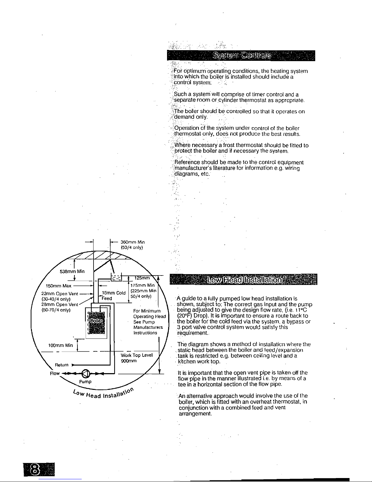
360mm Min
(50/4 only)
125mm
xk
r
kt
ri').
;;;;
O
Viltgl
ks
For optimum operating conditions, the heating system
'into which the boiler is installed should include a
-
control system.
Such a system will comprise of timer control and a
'
,
separate room or cylinder thermostat as appropriate.
The boiler should be controlled so that it operates on
demand only.
Operation of the system under control of the boiler
thermostat only, does not produce the best results.
Where necessary a frost thermostat should be fitted to
protect the boiler and if necessary the system.
Reference should be made to the control equipment
manufacturer's literature for information e.g. wiring
•
diagrams, etc.
175mrn Min
(225mm Min
50/4 only)
For Minimum
Operating Head
See Pump
Manufacturers
Instructions
538mm Min
150mm Max
22mm Open Vent
(30-40/4 only)
28mm Open Vent
(50-70/4 only)
100mm Min
I
Return
Row '1 I
CD
C
to
0(t
Iv
Head Insta
%
lla
•
A guide to a fully pumped low head installation is
shown, subject to: The correct gas input and the pump
being adjusted to give the design flow rate, (i.e. 11°C
(20°F) Drop). It is important to ensure a route back to
the boiler for the cold feed via the system, a bypass or
3 port valve control system would satisfy this
requirement.
The diagram shows a method of installation where the
static head between the boiler and feed/expansion
tank is restricted e.g. between ceiling level and a
•
kitchen work top.
It is important that the open vent pipe is taken off the
flow pipe in the manner illustrated i.e. by means of a
tee in a horizontal section of the flow pipe.
An alternative approach would involve the use of the
boiler, which is fitted with an overheat thermostat, in
conjunction with a combined feed and vent
arrangement.

Pressure
Gauge
Filling
Point
Pump
0
V I
Expansion
Vessel
Radiator
Circuit
Safety
Valve
Al
Vent
3 Litre
Top Up Bottle
(If Required)
A safety valve complying with the requirements of
BS 6750 Part 1 must be fitted close to the boiler on the
flow pipe by means of a horizontal or vertically upward
connection with no intervening valve or restrictions and
should be positioned to facilitate testing. The valve
should be pre-set and non-adjustable to operate at a
pressure of 3 bar (45 lbf/In9. It must be arranged to
discharge any water or steam through a pipe to a
safe outlet position.
,
--
IUSERMIESEMBEEMES
A pressure gauge of minimum range 0-4 bar
(0-60 lbf/In
2
) with a fill pressure indicator
must be fitted to the system, preferably at the
same point as the expansion vessel in an
easily visible position.
An expansion vessel complying with the
requirements of BS 4814 must be fitted to the
system by means of a connection close to the
inlet side of the circulating pump in accordance
with the manufacturers instructions, the
connecting pipe being unrestricted and not less
than 15mm
(
V
2
in) nominal size. The volume of the
vessel should be suitable for the system water content
and the nitrogen or air charge pressure should not be
less than the system static head. Further details of
sealed system design can be obtained from BS 5449:
Part 1 and the British Gas publication entitled
'Specifications for Domestic Wet Central Heating
Systems'.
I*4111.101W4.13/4.
-
System Drains
at Low Points
Max Boiler Flow
Temp = 82°C
Pr
cot
miciiii
el
*volytiikurn
_
c,
• ;C
oll- 4
5
-"icsin
"
4713a4 %-f-9--r-e-44
.7-
-it2-9,,terP
'co..
,
0
7 --Pe;
ko
.4115.09'ie
404.-k
4'
I--
Vessel Charge
Pressure (Bar)
1
Initial System
Pressure (Bar)
Multiply Total
Water Content
Of System by
(Litres)
0.5 -'
'0.5
1.0
1.5
2.0
0.067
0.112
0.207
0.441
1.0
1.5
2.0
0.087
0.152
0.330
1.5
2.0
0.125
0.265
Vetherohardtplessure
nitialljjlein-preicute
5
Ekpans
yatem_volume
0' 5
raire
/
rot
-t
e n
,
41,6
'Op Oa
Pe
NOTE
w
of the calce‘
a
e27
0
-1
0‘
e
-9
e,
ta
ble
se
siz
e
e
then the neXt
-nould be used.
- 0 10,i-
A filling point and an approved stop valve to BS 1010
must be fitted at low level and the method used for
fillingthe system should be approved by the local
Water undertaking. For further details see BS 6798.
afAXEMEISYSIEMEMENZEMES
A method of replacin9 water lost from the system
should be provided either by means of a make up
vessel of not more than 3 litres (5 pints) capacity,
mounted above the highest point of the system, or by
pre-pressurisation of the system.
A method of venting the system during filling and
commissioning must be provided by fitting automatic
air vents or by venting manually.
-Worn
,
Am; .
0
tom
The hot water storage vessel must be of the indirect
coil type. All components used in the system must be
suitable for operation at 110°C (230°F) and at the
pressure allowed by the safety valve.
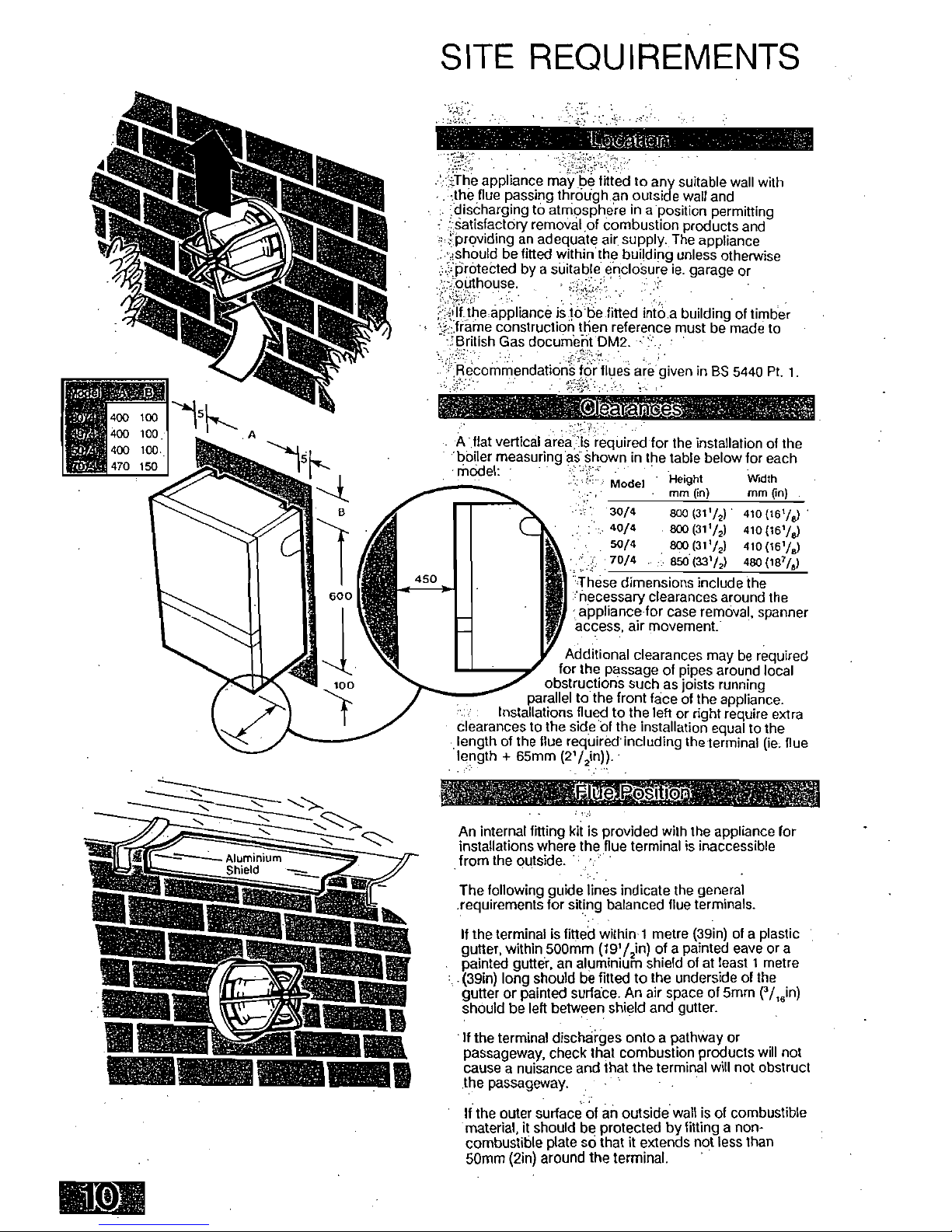
SITE REQUIREMENTS
.0-he appliance maY be fitted to any suitable wall with
the flue passing through .an outside wall and
.discharging to atmosphere in a position permitting
7 "[Satisfactory removal of combustion products and
.:
.
fProviding an adequate air
.
supply. The appliance
:.should be fitted within the building unless otherwise
::protected by a suitable enclosure ie. garage or
'.:.cauthouse.
lithe appliance is to be fitted into a building of timber
::frarne construction then reference must be made to
.:British Gas document DM2.
RecornmendatiOnS for flues are given in BS 5440 Pt. 1.
'SS
.
A flat vertical area
le
required for the installation of the
'boiler measuring aS shown in the table below for each
Height
Width
Model
mm (in) mm (in)
30/4
800 (31
1/2
)
410 (161/)
40/4
800(311/2)
410 (161/8)
50/4
800(3172)
410(15h/)
70/4
850 (3372)
480 (1874)
obstructions such as joists running
parallel to the front face of the appliance.
clearances to the side of the installation equal to the
length of the flue reqUired including the terminal (ie flue
length + 65mm (2V2in)).
Model:
These dimensions include the
'necessary clearances around the
appliance for case removal, spanner
access, air movement:
Additional clearances may be required
for the passage of pipes around local
Installations flued to the left or right require extra
(SNP
An internal fitting kit is provided with the appliance for
installations where the flue terminal is inaccessible
from the outside.
The following guide lines indicate the general
.requirements for siting balanced flue terminals.
If the terminal is fitted within-1 metre (39in) of a plastic
gutter, within 500mm (1972in) of a painted eave or a
painted gutter, an aluminium shield of at least 1 metre
(39in) long should be fitted to the underside of the
gutter or painted surface. An air space of 5mm (116in)
should be left between shield and gutter.
If the terminal discharges onto a pathway or
passageway, check that combustion products will not
cause a nuisance and that the terminal will not obstruct
the passageway.
If the outer surface of an outside wall is of combustible
material, it should be protected by fitting a non-
combustible plate so that it extends not less than
50mm (2in) around the terminal.
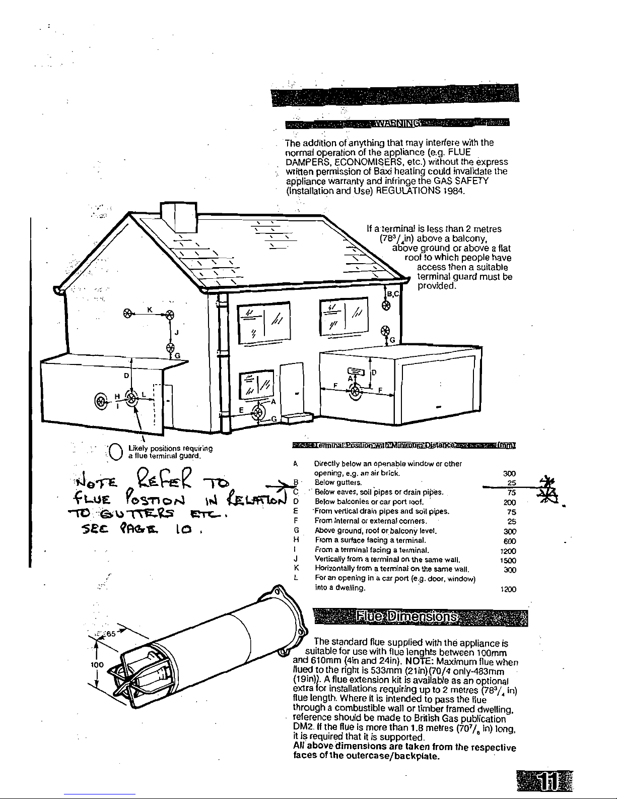
-
• "ft.3;
If a terminal is less than 2 metres
(78
3
/4in) above a balcony,
above ground or above a flat
roof to which people have
access then a suitable
terminal guard must be
provided.
The addition of anything that may interfere with the
normal operation of the appliance (e.g. FLUE
DAMPERS, ECONOMISERS, etc.) without the express
written permission of Baxi heating could invalidate the
appliance warranty and infringe the GAS SAFETY
(Installation and Use) REGULATIONS 1984.
Likely positions requiring
a flue terminal guard.
•
.
41
0
1-€. sag-ce
41-0E 9os-ri ()NI
CELiriend
D
--ro .t.)-rW...?..s
5Et.
VIGIL 10
em
r
—
VMIEMMElliThAffumilolDiatitilir
w
r
icnry
' 11
The standard flue supplied with the appliance is
suitable for use with flue lenghts between 100mm
and 610mm (4in and 24in). NOTE: Maximum flue when
flued to the nght is 533mm (21in)(70/4 only-483mm
(Win)). A flue extension kit is available as an optional
extra for installations requiring up to 2 metres (78
3/4
in)
flue length. Where it is intended to pass the flue
through a combustible wall or timber framed dwelling,
reference should be made to British Gas publication
DM2. If the flue is more than 1.8 metres (70
7
/, in) long,
it is required that it is supported.
All above dimensions are taken from the respective
faces of the outercase/backplate.
A
Directly below an openable window or other
opening, e.g. an air brick.
Below gutters.
Below eaves, soil Pipes or drain pipes.
Below balconies or car port roof.
From vertical drain pipes and soil pipes.
From internal or external corners.
Above ground, roof or balconY level.
From a surface facing a terminal.
From a terminal facing a terminal.
Vertically from a terminal on the same wall.
K
Horizontally from a terminal on the same wall.
L
For an opening in a car port (e.g. door, window)
into a dwelling.
300
25
75
200
75
25
300
600
1200
1500
300
1200

Ai5lists?
Where the appliance is installed in a cupboard or
compartment, air vents are required (for cooling
purposes) in the cupboard or compartment at
high and low level which may communicate
with a room or direct to outside air.
Detailed recommendations for air supply are
given in BS 5440: Part 2.
An existing cupboard or compartment may be
used, provided that it is modified for the
purpose. Recommendations for air supplies
and details of essential cupboard
compartment design are given in BS 5440:
Part 2.
NOTE: Both air vents must communicate with
the same room or both be on the same wall to
outside air.
104
,n2
52cm2
(I5.84,
2
)
FREE AREA
osin2) FREE AREA
I35cm
2
67.5cm2
(20,481n;
FREE AREA
(10.24in2)
FREE
AREA
17Icm
2
85.5cm2
/26in2) FREE AREA
113,n2) FREE AREA
240cm
2
120cm2
(36,46
2) FREE AREA
(I
Eigin21
FREE AREA
The gas installation should be in accordance with
85 6891:1988.
The connection of the appliance is
RC'/
2
(1/?in
BSPT internal) located at the
bottom right hand side.
Ensure that the pipework from the meter to
the appliance is of adequate size. Do not
use pipes of a smaller diameter than the
appliance gas connection.
Electrica Supply
External wiring must be correctly earthed, polarised
and in accordance with CURRENT I.E.E. WIRING
REGULATIONS.
The mains supply required is 240V — 50Hz fused at 3A.
NOTE: The method of connection to the electricity
supply must facilitate complete electrical isolation of
the appliance, preferably by the use of a fused three
pin plug and unswitched shuttered socket outlet, both
complying with the requirements of BS 1363.
Alternatively, connection may be made via a fused
double-pole isolater with a contact separation of at
least 3mm in all poles and serving the appliance and
system controls only.
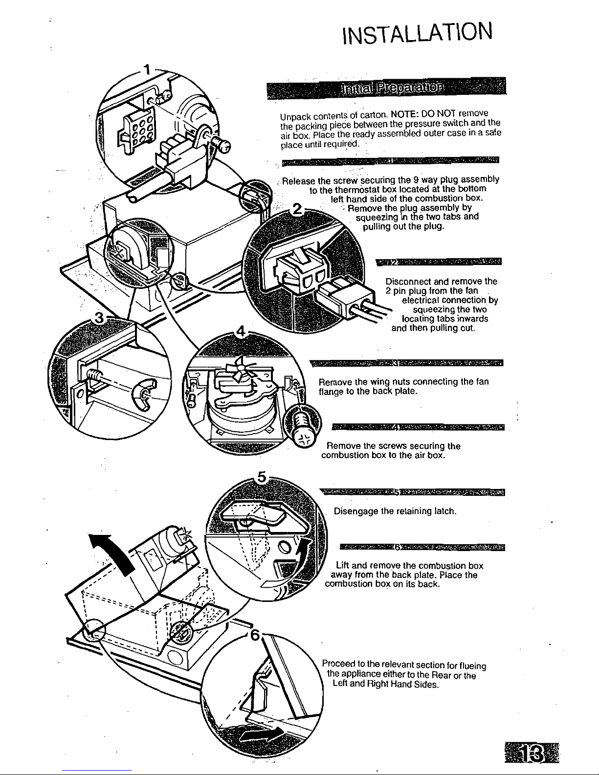
Unpack contents of carton. NOTE: DO NOT remove
the packing piece between the pressure switch and the
air box. Place the ready assembled outer case in a safe
place until required.
Release the screw securing the 9 way plug assembly
to the thermostat box located at the bottom
left hand side of the combustion box.
2
Remove the plug assembly by
squeezing in the two tabs and
pulling out the plug.
Disconnect and remove the
2 pin plug from the fan
electrical connection by
squeezing the two
locating tabs inwards
and then pulling out.
ISSIESIESSZEIMMEIBBEZIEEMBIEBEESES
Remove the wing nuts connecting the fan
flange to the back plate.
Remove the screws securing the
combustion box to the air box.
NEESZESIEMESIIMMEMEUESSMEEME8
Disengage the retaining latch.
MAIMIIITIZEKOZEMEESEZICIER
Lift and remove the combustion box
away from the back plate. Place the
combustion box on its back.
Proceed to the relevant section for flueing
the appliance either to the Rear or the
Left and Right Hand Sides.
INSTALLATION
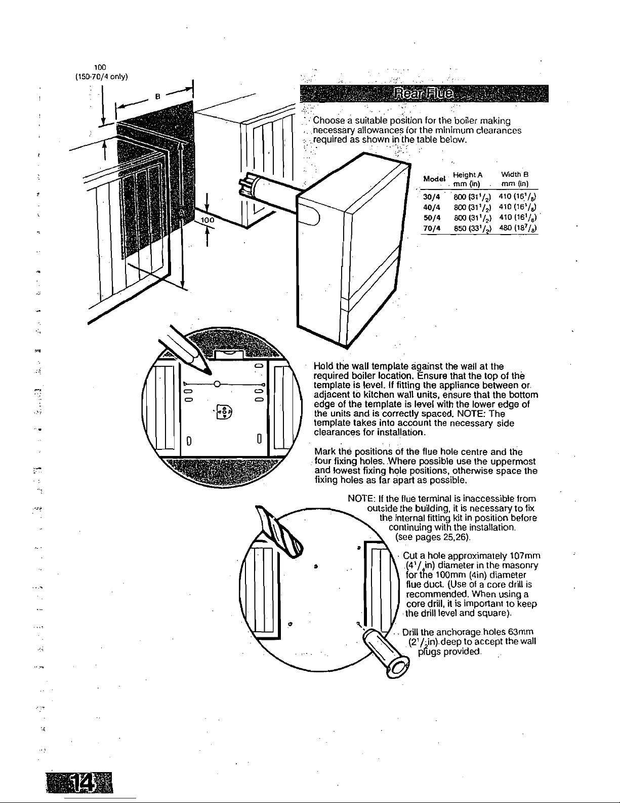
100
(150-70/4 only)
Choose a suitable position for the boiler making
necessary allowances for the minimum clearances
required as shown in the table below.
Model
Height A
mm On).
Width B
mm (in)
30/9
800 (31i/2)
410
(181/8)
40/4
8C0(31'/2)
410
(151/8)
50/4
800 (311/2)
410
(161/8)
70/4
850 (331/2)
480
(187/8)
Hold the wall template against the wall at the
required boiler location. Ensure that the top of the
template is level. If fitting the appliance between or.
adjacent to kitchen wall units, ensure that the bottom
edge of the template is level with the lower edge of
the units and is correctly spaced. NOTE: The
template takes into account the necessary side
clearances for installation.
Mark the positions of the flue hole centre and the
four fixing holes. Where possible use the uppermost
and lowest fixing hole positions, otherwise space the
fixing holes as far apart as possible.
NOTE: If the flue terminal is inaccessible from
outside the building, it is necessary to fix
the internal fitting kit in position before
continuing with the installation.
(see pages 25,26).
• Cut a hole approximately 107mm
(41/ in) diameter in the masonry
for the 100mm (4in) diameter
flue duct. (Use of a core drill is
recommended. When using a
core drill, it is important to keep
the drill level and square).
Drill the anchorage holes 63mm
(2
1
/,in) deep to accept the wall
plugs provided.
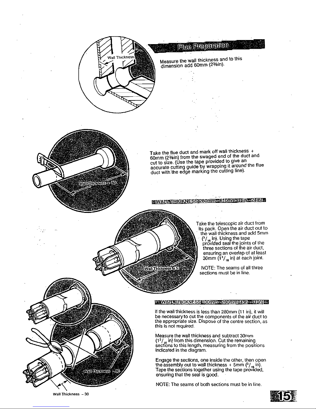
Measure the wall thickness and to this
dimension add 60mm (23/8in).
Take the flue duct and mark off wall thickness +
60mm (2
3
/ein) from the swaged end of the duct and
cut to size. (Use the tape provided to give an
accurate cutting guide by wrapping it around the flue
duct with the edge marking the cutting line).
.
2
WA
le ES -
9
80
il
--iftv
•
• tii)-'+'
lluie
Take the telescopic air duct from
its pack. Open the air duct out to
the wall thickness and add 5mm
(9,
6 in). Using the tape
provided seal the joints of the
three sections of the air duct,
ensuring an overlap of at least
30mm (1
3/,6
in) at each joint
NOTE: The seams of all three
sections must be in line.
tv_WA U " OKNESS
smth-Th-o.
tie an
etrimonak-;:
If the wall thickness is less than 280mm (11 in), it will
be necessary to cut the components of the air duct to
the appropriate size. Dispose of the centre section, as
this is not required.
Measure the wall thickness and subtract 30mm
(
13
/
16
in) from this dimension. Cut the remaining
sections to this length, measuring from the positions
indicated in the diagram.
Engage the sections, one inside the other, then open
the assembly out to wall thickness + 5mm
(915
in).
Tape the sections together using the tape provided,
ensuring that the seal is good.
NOTE: The seams of both sections must be in line.
Wall Thickness —30
4w-40ov A
i.:4111;1
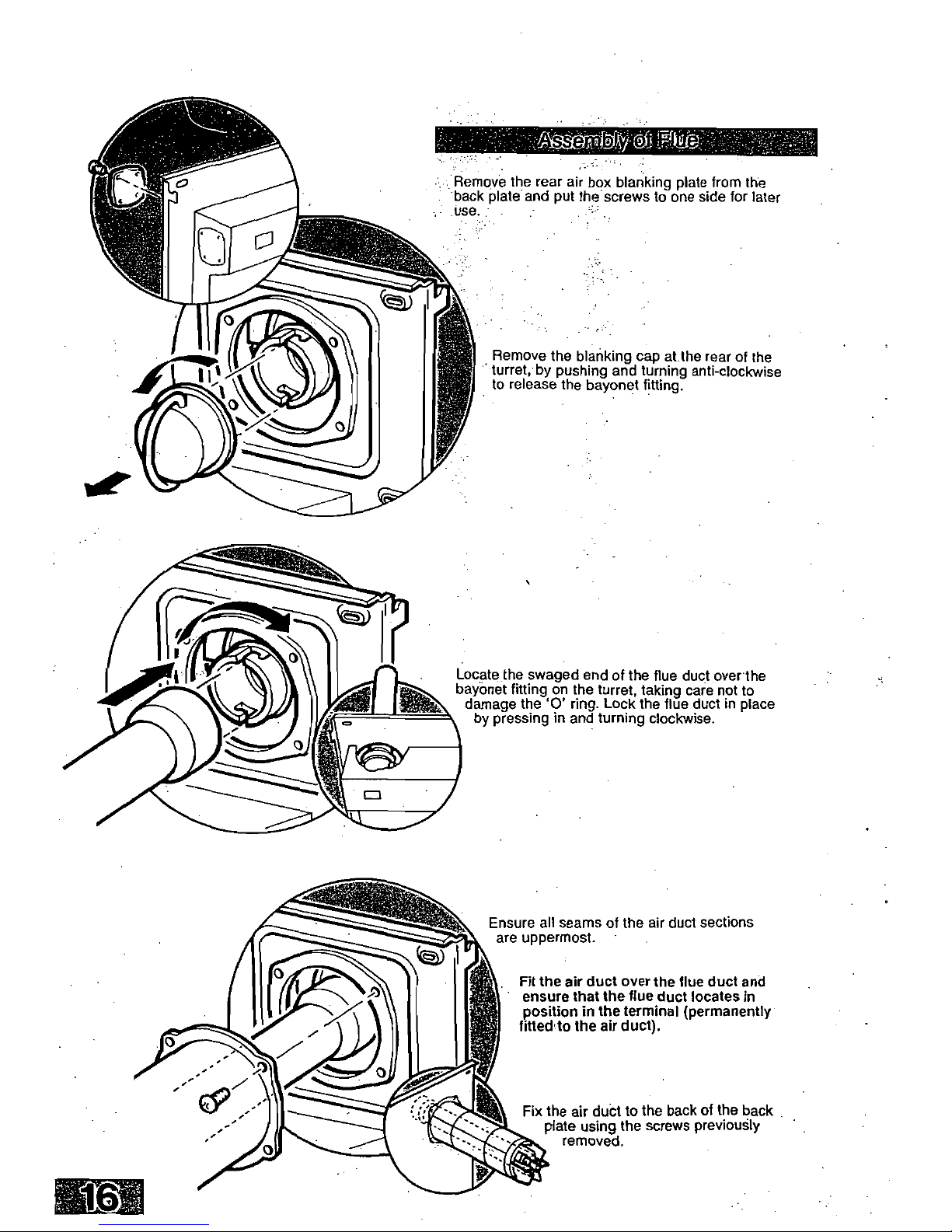
Remove the rear air box blanking plate from the
•
back plate and put the screws to one side for later
Remove the blanking cap at the rear of the
turret, by pushing and turning anti-clockwise
to release the bayonet fitting.
Locate the swaged end of the flue duct over the
bayonet fitting on the turret, taking care not to
damage the '0' ring. Lock the flue duct in place
by pressing in and turning clockwise.
Ensure all seams of the air duct sections
are uppermost.
Fit the air duct over the flue duct and
ensure that the flue duct locates in
position in the terminal (permanently
fitted to the air duct).
Fix the air duct to the back of the back
plate using the screws previously
removed.
 Loading...