

Baxi Solo Innova Instructions Manual
INSTRUCTIONS
Solo Innova
Page 1
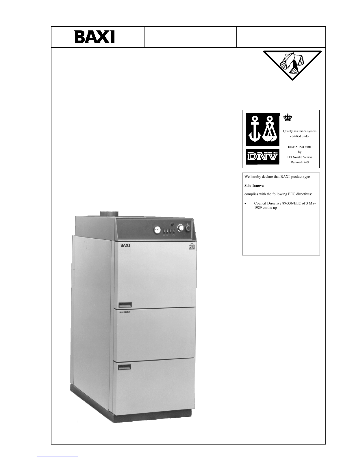
Solo Innova
Wood-fired central heating boiler
Section
User guide 1
Adjustment 2
Installat ion 3
Technical specifications and circuit and system diagrams 4
Installation protocol 5
Instruktion Sprog/Nr./Rev/Dato
EN/137409/00/24-06-2002.
DANAK
Reg. no.
Quality assurance system
certified under
DS/EN ISO 9001
by
Det Norske Veritas
Danmark A/S
We here by decl are that BAXI produ ct type
Solo Innova
complies with the following EEC directives:
• Council Directive 89/336/EEC of 3 May
1989 on the approximation of the laws of
the Member States relating to
electromagnetic compatibility as
amended by 92/31/EEC and 93 /68/EEC
• Council Directive 73/23/EEC of 19
February 1973 on the harmonisation of
the laws of Member States relating to
electrical equipment designed for use
within certain voltage limits as amended
by 93/68/EEC
INSTRUCTIONS
Solo Innova
Page 2
CONTENTS
This user guide is divided into several sections. Figure numbers refer to the corresponding sections. Fig. no. 1.1.1 thus
refers to Section 1.1.1. The symbol (#)-no. is used if several pictures belong to one section.
Section Page
1 USER GUIDE......................................................................................................................................... 3
1.1 D
ESCRIPTION OF BOILER
..................................................................................................................... 3
1.2 S
AFETY PRECAUTIONS
........................................................................................................................ 6
1.3 O
PERATING HINTS
.............................................................................................................................. 7
1.4 D
ESCRIPTION OF THE APPARATUS
...................................................................................................... 10
1.5 T
ROUBLESHOOTING
.......................................................................................................................... 12
1.6 M
AINTENANCE
................................................................................................................................. 13
1.7 C
LEANING
........................................................................................................................................ 14
2 AUTOMATIC OPERATION – SAVING ENERGY ........................................................................... 15
2.1 C
ONTROLLING THE BOILER WITH THE WEATHER COMPENSATION SYSTEM
........................................... 15
3 INSTALLATION.................................................................................................................................. 16
3.1 S
TANDARDS AND REGULATIONS
........................................................................................................ 16
3.2 S
YSTEM TYPES
................................................................................................................................. 16
3.3 I
NSTALLATION
................................................................................................................................. 17
3.4 S
TANDARD DELIVERY
:...................................................................................................................... 17
3.5 I
NSTALLATION AND PIPE CONNECTIONS
............................................................................................. 17
3.6 E
XPANSION TANK, SAFETY LINES AND PUMP SIZE
............................................................................... 18
3.7 E
LECTRICAL CONNECTION
................................................................................................................ 18
3.8 C
OMMISSIONING THE SYST EM
........................................................................................................... 19
4 TECHNICAL SPECIFICATIONS AND CIRCUIT DIAGRAMS ...................................................... 20
4.1 B
OILER TECHNICAL SPECIFICATIONS
.................................................................................................. 20
4.2 C
IRCUIT DIAGRAMS
.......................................................................................................................... 21
4.3 S
YSTEM LAYOUT
.............................................................................................................................. 23
5 INSTALLATION PROTOCOL, BOILER SYSTEM.......................................................................... 24
5.1 M
EASURED AND SET VALUES
............................................................................................................ 24
Specifications are subject to change without notice. No responsibility can be accepted for printing errors.
INSTALLATION GUIDE
for BAXI - SOLO INNOVA boiler
The SOLO INNOVA is used to generate hot water. The permissible outflow temperature is 95°C and
the permissible total excess pressure is 2.5 bar, measured at the deepest point in the boiler system/the
boiler.
Please note the technical specifications which are given in the table below and the type plate.
The boiler should be installed as per the accompanying installation and user guide.
Please observe local regulations when installing the boiler and the heating system.
Regulation and limitation of the heating is by switching the fan by means of TR (temperature
controller) and STB (safety temperature limiter). A max. draught of 20 Pascal may not be exceeded.
All boilers are given a water pressure test of 3.25 bar in the factory.
Apart from the accompanying installation instructions, a user guide with all requisite information must
be kept at/hung on the boiler after the boiler has been set up.
Tarm, 06.03.1997 BAXI A/S
Smedevej
6880 Tarm
Denmark

INSTRUCTIONS
Solo Innova
Page 3
1 User guide
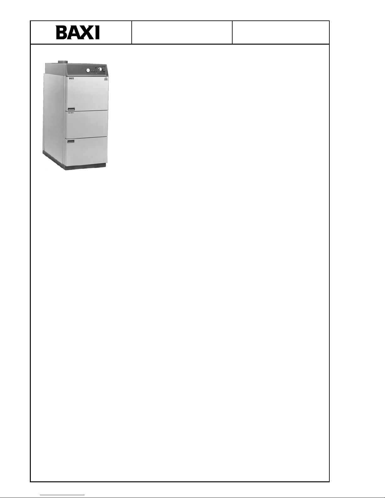
1.1
Description of boiler
15
14
13
12
11
10
9
8
7
1
2
3
4
5
6
Fig. 1.1
1. Control panel
2. Filling door
3. Primary air control
4. Secondary air control
5. Ash door
6. Sight glass
7. Exhaust stack
8. Cleaning damper
9. Induced-draught fan
10. Type plate
11. Cooling spiral*
12. Flue gas turbulators
13. Heat exchanger pipe
14. Filling chamber
15. Fuel tunnel
*Can be installed to left or right.

INSTRUCTIONS
Solo Innova
Page 4
INSTRUCTIONS
Solo Innova
Page 5
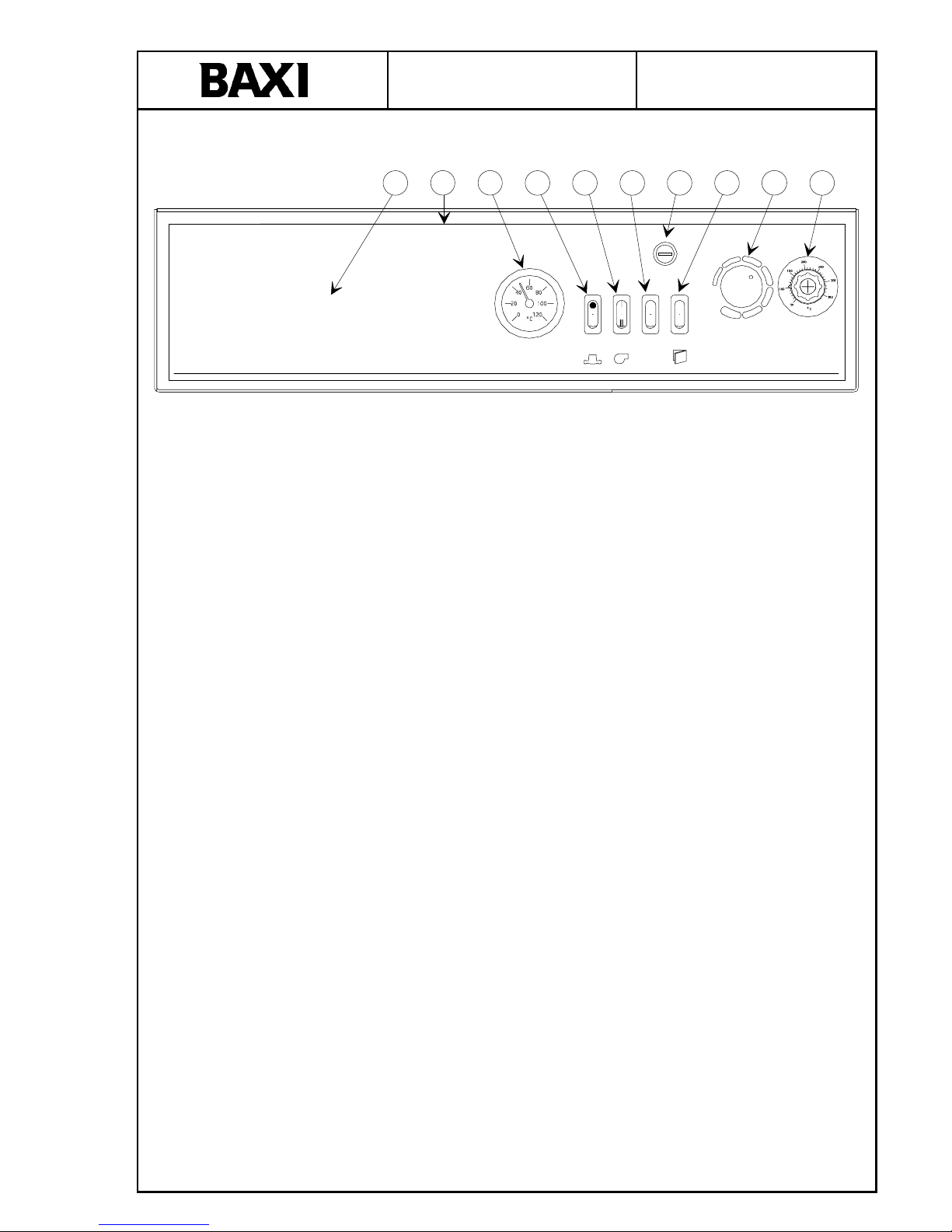
1.1.1 Control panel (standard)
The boiler temperature is adjusted from here.
See also Section 1.4.
A D C F N H O I PE
210680.1 1
Fig. 1.1.1
(A) Space for weather compensation system
(C) Thermometer
(D) Fuse
(E) Switch for circulation pump
(F) Switch for fan
(H) Overheating thermostat – Restar ting knob
(I) Thermostat
(N) Reset switch
(O) Switch to open door
(P) Minimum thermostat
1.1.2 Filling door
The big filling door makes adding fuel easy.
1.1.3 Primary air control
The primary air of combustion is set here.
1.1.4 Secondary air control
The secondary air of combustion is set here.
1.1.5 Ash door
Combustion takes place behind this door and ashes are removed through it.
1.1.6 Sight glass
Combustion can be monitored through the sight glass.
1.1.7 Exhaust stack
An exhaust pipe is ducted to the chimney.
1.1.8 Induced-draft fan
Ensures the required air supply for combustion.
1.1.9 Cleaning damper
Detachable cleaning damper for cleaning the heat exchanger pipe.
1.1.10 Type plate
Indicates factory no. and type and other information required to order spar e parts.
Factory no. and type can be noted in Section 5 on the last page of this user guide.
1.1.11 Cooling spiral
Thermal protection.
1.1.12 Flue gas turbulators
Ensure the correct flue gas temperature.
1.1.13 Heat exchanger pipe
The heat is transferred to the boiler water here.
1.1.14 Filling chamber
For the firewood.
1.1.15 Fuel tunnel
Air of combustion is added to the flue gases and they are burned here, ensuring high
efficiency.
Description of more important components (layout see Fig. l.l).
INSTRUCTIONS
Solo Innova
Page 6
1.1.16 Function (See Fig. l.l)
The Solo Innova is made for burning pieces of natural wood.
An important feature is the built-in induced-draft fan (9).
Both primary and secondary air are added to the combustion chamber via an air channel
at exactly the speed required for uniform combustion.
The primary air (3) is ducted to the lower section of the filling chamber.
The secondary air (4) is ducted further through the fuel tunnel, where it is heated and
divided via two channels and the combustion nozzle. It is then blown directly into the
flame at high speed to complete the combustion.
A noteworthy construction feature is the special ceramic fuel tunnel (15) in the heart of
the boiler which ensures that the combustion temperature reaches more than 1000°C.
Combustion is efficient and soot-free, and ensures optimal economy.
The heat is supplied to the boiler water via the heat exchanger pipe (13) at the rear of
the boiler.
Mixing of the air of combustion from the fan and the gases from the wood in the
correct proportions is a prerequisite for optimal and environmentally friendly
burning of the wood with the highest efficiency.
Operation of the fan assumes that the boiler can discharge its heat continually. The
Solo Innova must always be connected to a buffer tank of adequate size.
1.1.17 Maintenance and guarantee
The guarantee is described in more detail in the BAXI guarantee certificate supplied
with the boiler.
The guarantee is valid only when the system is connected to a buffer tank.
Complaints
Please contact the technician/dealer who installed/supplied your boiler, who will
forward your complaint as required to the factory. Complaints may also be addressed
directly to the factory.
1.2
Safety precautions
1.2.1 Responsibility
The operator is responsible for running the boiler and complying with firing
instructions. Failure to comply with the instructions can result in reduced efficiency and
increased environmental impact as the flue gases will not be as clean as they should be.
Faulty operation can also reduce boiler life. Correct operation (and installation) is the
best guarantee of long life and minimal impact on the environment. It is assumed that
the operator possesses the appropriate motivation and the correct attitude for firing with
wood, as a certain amount of work is still required to be able to “harvest” the
advantages of this environmentally friendly and economical form of heating.
1.2.2 Safety precautions
If faults or defects are found, they must be promptly rectified by a qualified heating
engineer. Flue gas pipes, ventilation channels, fresh air ducts etc. may not be closed off
or blocked. Inflammable liquids or materials may not be placed near the boiler.
1.2.3 Maintenance
The operator must maintain and clean the boiler and any extra equipment in accordance
with:
– general practice
– the instructions in this user guide
– the instructions for any optional equipment/accessories
– and the terms described in the appropriate guarantee certificate
– (see Section 1.7 Cleaning, 1.6 Maintenance and the boiler’s guarantee
certificate).
Fig. 1.1.16
INSTRUCTIONS
Solo Innova
Page 7
1.3
Operating hints
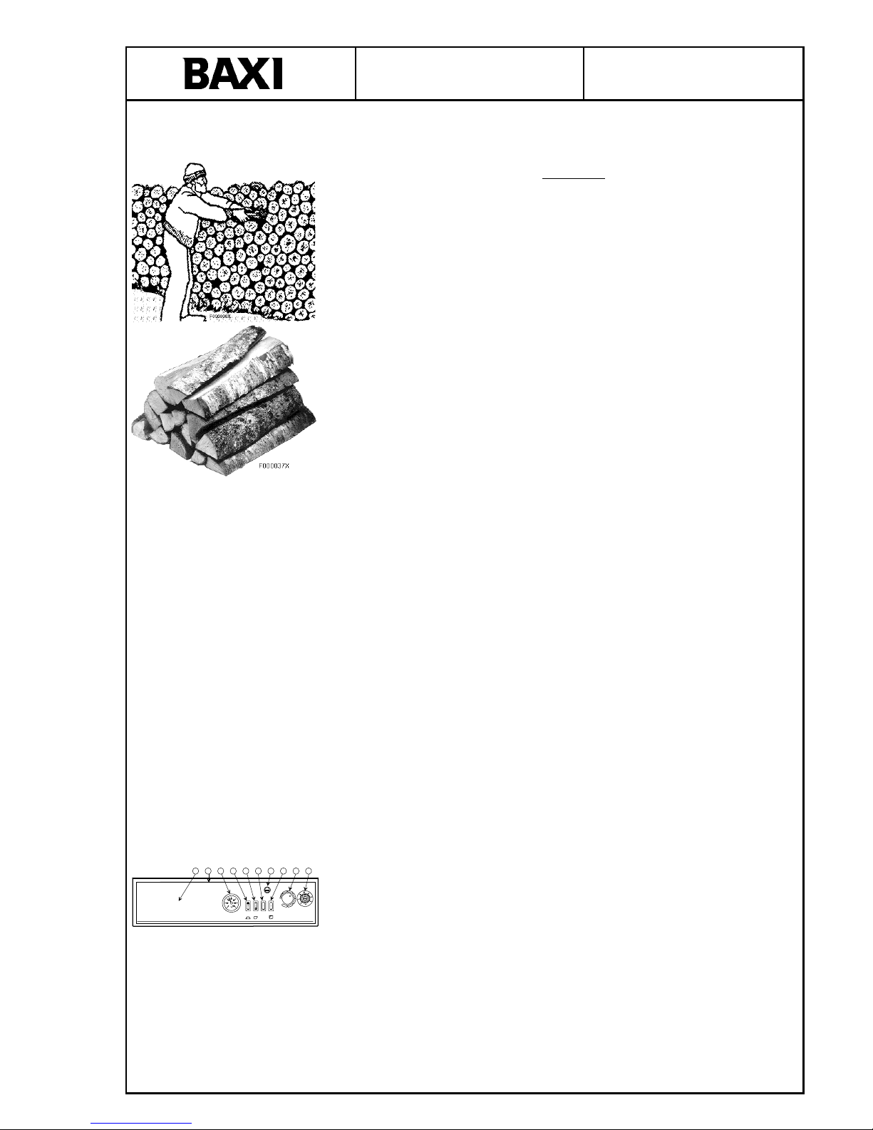
1.3.1 Wood as fuel
The Solo Innova is made to burn natural forest wood. Both hardwood and softwood are
suitable, but oak should not be burned as the only source of wood for long periods
because of its high acid content.
The wood must be dry, i.e. moistur e content 15-25%. The wood must be dry for good
combustion and to achieve its best calorific value.
The wood will dry out most quickly if it is cut into the appropriate length and split into
pieces 10-12 cm thick. The best length is 1/2 metre for the Solo Innova 30-50 and 1/3
metre for the Solo Innova 20.
The wood is best stored in the open air under cover, but it can also be stored uncovered.
The wood will dry most quickly if it is carefully stacked alternatively lengthwise and
crosswise so that air can penetrate into the stack.
The wood should be stored for at least one and a half years.
Chopped wood (e.g. waste wood and wood chips) are less suitable as fuel. On the one hand they can fall
down the gap between the ceramic bricks and on the other hand it can be difficult to
control the combustion process effectively. The disadvantages can, for example, include
reduced efficiency, soot etc. Impregnated or painted wood is unsuitable as fuel. The
Solo Innova is designed for forest wood. Wood is an environmentally friendly fuel as it
is CO
2
-neutral.
Briquettes Wood briquettes or straw can also be used as fuel, e.g. with a diameter of 60 mm and a
length of 50-100 mm.
Excessively small and compact pieces of wood or straw pellets are not suitable.
Coal Coal cannot be used as it becomes too compact and closes the fuel slit.
Maximum fill height The filling chamber can be filled to the top.
1.3.2 Before using
1. Check the water pressure before using the system.
2. The pump and the fan must be switched off when filling with water. This is most
easily done at the main switch on the wall. (See Section 1.6 - Maintenance).
N.B.: Water may not be added to the boiler while it is running.
3. When filling, the system must be bled via the venting screw.
1.3.3 Commissioning the boiler
1. Switch on the main switch on the wall.
2. Fill with fuel (see Section 1.3.8 or 1.3.9).
3. Switch on the switches for the pump (E) and the fan (F). Set the thermostat (I) to
the desired temperature. Press the reset button (N).
4. Light the fire as in Section 1.3.7.
5. The boiler will start if heating is required.
6. See Section 1.5 – Troublesh ooting if there are problems starting.
1.3.4 Shutting down the boiler
1. Switch off the boiler at the main switch on the wall.
2. Then switch off the boiler/the circulation pump at switches (E) and (F).
A D C F N H O I PE
210680.11

INSTRUCTIONS
Solo Innova
Page 8
1.3.5 Connecting a buffer tank
The correct proportions of air of combustion from the fan and gases from the wood are a
prerequisite for optimal and environmentally friendly burning of the wood with the
highest possible efficiency. Operation of the fan assumes that the boiler can continually
discharge its heat. BAXI therefore recommends that a buffer tank always be connected.
1.3.6 Tar in the combustion chamber
Tar deposits are not normally a problem in a Solo Innova which is fired as directed (see
section 1.3.12 – Operation with buffer tank).
1.3.7 Preheating
1)
Switch on the fan with the switch on the control panel (F) (Setting I).
2)
Press door open switch O and open the door.
3)
Insert pieces of wood and paper.
4)
Light the wood and the paper. Close the door.
5)
Switch on the fan switch (F).
6)
Press the reset switch (N). The fan will start.
7)
Add fuel when the embers are about 150 mm high.
– Combustion will be in progress after about 5-10 minutes.
1.3.8 Putting in wood
It is very important not to add so much wood than that the heat of combustion cannot be
stored in the reservoir. The maximum temperature should only be reached when the
wood has burned. THE FAN SHOULD NOT SWITCH OFF BEFORE THE WOOD
HAS BURNED*) IF THE FAN SWITCHES OFF BEFORE THIS, THERE IS TOO
MUCH WOOD. MAKE THE BEST POSSIBLE USE OF THE RESERVOIR AND DO
NOT ADD TOO MUCH WOOD. See also 1.3.12
*) Waiting time and starting/stopping of the fan do not give clean combustion. It is also
bad for the boiler as condensation will occur in the filling chamber, causing corrosion in
the steel walls.
1.3.9 Adding wood
1)
Switch on the fan with the switch on the control panel (F) (Setting I).
2)
Press the door open switch.
3)
Open the filling door 2 cm with the left hand.
4)
Wait about 20 seconds.
5)
Slowly open the door.
6)
Add wood. Try to stack the wood as evenly as possible.
7)
Close the door.
8)
Switch on the fan switch (F).
9)
Press the reset switch (N).
1.3.10 Daily firing and warming up
The warming up procedure for daily use is the same as was done the first time. Use
pieces of wood and paper. Stir up the ashes when the fire is underway. Add more wood,
close the door and switch on the fan. The newly added wood will now ignite.
Operation
The fuel tunnel (behind the ash door) must be kept reasonably free of ashes and small
half-burned pieces of wood. Use the scraper to keep the tunnel clean and leave the small
pieces of wood in front of the tunnel, where they will burn. It is useful to check the
tunnel each time it is warmed up and to clean carefully as required.
Storing the fuel. Wood may not be stored in the boiler room. The wood is best
protected from rain, stored under cover.
1.3.11 Transport protectors
The transport protectors for the ceramic bricks are made of wood and will quickly burn.
Do not try to remove them.
 Loading...