

Baxi LUNA DUO-TEC 1.70, LUNA DUO-TEC 1.110 User Manual

A
LUNA DUO-TEC 1.70
LUNA DUO-TEC 1.110
en CONDENSING GAS FIRED WALL MOUNTED COMBINATION BOILER
User Guide
fr CHAUDIÈRE MURALE À GAZ À CONDENSATION À DEUX SERVICES
Notice pour l'installateur

7703476.01 (1-03/18)
2
User Guide (en)
Dear Customer,
Thank you for purchasing your Baxi product. We hope your new boiler will meet all your heating needs and satisfy your expectations
with it's reliability, simplicity and ease of use. Do not dispose of this booklet without reading it in it's entirety as it contains very
useful information; which will help you to run your boiler correctly and efciently.
Do not leave any parts of the packaging (plastic bags, polystyrene, etc.) within children's reach as they are a potential source of
danger.
"Should overheating occur or the gas supply fails to shut off, do not turn off or disconnect the electrical supply to the
pump. Instead, shut off the gas supply at a location external to the appliance"
Do not use this boiler if any part has been under water. Immediately call a qualied service technician to inspect the
boiler and replace any part of the control system or gas control which has been under water.
CONTENT
SAFETY INFORMATION ..............................................................................................................................................................................3
DEFINITIONS ...............................................................................................................................................................................................3
SPECIAL ATTENTION BOXES .....................................................................................................................................................................3
OTHER DEFINITIONS ..................................................................................................................................................................................3
BEFORE INSTALLING AND WHILE SERVICING THE BOILER ..................................................................................................................4
DURING BOILER OPERATION ....................................................................................................................................................................4
BOILER WATER ...........................................................................................................................................................................................4
FREEZE PROTECTION FLUIDS ..................................................................................................................................................................5
CONDENSATE REMOVAL SYSTEM............................................................................................................................................................5
1. INTRODUCTION ...........................................................................................................................................................................................6
1.1 MANUFACTURER'S LIABILITY ....................................................................................................................................................................7
1.2 INSTALLER'S LIABILITY ..............................................................................................................................................................................7
1.3 OPERATOR/ULTIMATE OWNER LIABILITY ................................................................................................................................................7
2. OPERATING THE BOILER ...........................................................................................................................................................................7
2.1 CONTROL PANEL ........................................................................................................................................................................................8
2.2 USER-LEVEL PARAMETERS ......................................................................................................................................................................9
2.2.1 READING MEASURED VALUES..................................................................................................................................................................10
2.2.2 STATUS AND SUB-STATUS .........................................................................................................................................................................11
3. TROUBLESHOOTING ..................................................................................................................................................................................12
3.1 SHOUTDOWNS AND LOCK-OUTS .............................................................................................................................................................14
4. ROUTINE SERVICING .................................................................................................................................................................................16
5. DISMANTLING, DISPOSAL AND RECYCLING ...........................................................................................................................................16
3
User Guide (en)
7703476.01 (1-03/18)
SAFETY INFORMATION
DEFINITIONS
The following dened terms are used throughout this manual to bring attention to the presence of hazards at various risk levels,
or to important information concerning the product.
SPECIAL ATTENTION BOXES
DANGER
"DANGER" indicates an imminently hazardous situation which, if not avoided, will result in death or serious injury.
WARNING
"WARNING" indicates a potentially hazardous situation which, if not avoided, could result in death or serious injury. If
the information in this manual is not followed exactly, a re or explosion may result causing property damage, personal
injury or loss of life.
CAUTION
"CAUTION" indicates a potentially damaging situation which, if not avoided, could result in minor injuries and
substantial product or property damage.
NOTICE
"NOTICE" indicates recommendations made by BAXI for the installers which help to ensure optimum operation and
longevity of the equipment.
OTHER DEFINITIONS
Licensed Qualied Installer / Service Technician - any individual, rm, corporation or company that either directly or through
a representative is engaged in the installation, replacement, repair or servicing of gas piping, venting systems, appliances,
components, accessories, or equipment, and whose representative is experienced and trained, in such work and has complied
with the requirements of the authority having jurisdiction.
STATE/FEDERAL REGULATIONS PERMIT THE INSTALLATION OF THIS PRODUCT ONLY BY AUTHORIZED GAS
CONTRACTORS. HOWEVER, BAXI ADVISES THAT ONLY CONTRACTORS TRAINED IN THE SPECIFIC DETAILS OF THIS
BAXI PRODUCT MUST UNDERTAKE INSTALLATION.
Service - the supply, installation, or maintenance of goods carried out by a Qualied Installer / Service Technician.
Gas Supplier - A party that sells the commodity of Natural Gas (Gas A) or LPG (Gas E).
Domestic - Relating to household usage as opposed to commercial usage.
Domestic Water - Potable drinking water (tap water).
Combustion - The act or process of burning; wherein a fuel is combined with oxygen, usually at high temperature, producing
heat.
Combustion Air - Air that is drawn into an appliance to mix with fuel and support combustion.
Flue - an enclosed passageway for conveying combustion gases.
Calibrate - make ne adjustments or divide into marked intervals for optimal measuring.
Appliance - a device to convert gas into energy; the term includes any component, control, wiring, piping or tubing required to be
part of the device.
Boiler - an appliance intended to supply hot liquid for space-heating, processing or power purposes.
Two Pipe System - This type of venting allows for exhaust ue and intake air piping to be separated from each other. Fresh air
may be drawn in at a different area from where the ue terminal is located.
WARNING
Failure to adhere to the guidelines on this page could result in severe personal injury, death or substantial property
damage.
7703476.01 (1-03/18)
4
User Guide (en)
WARNING
If the information in these instructions is not followed exactly, a re or explosion may result causing property damage,
personal injury or death.
Do not store or use gasoline or other ammable vapors and liquids in the vicinity of this or any other appliance.
WHAT TO DO IF YOU SMELL GAS
• Do not try to light any appliances.
• Do not touch any electrical switches; do not use any phones in your building.
• Immediately call your gas supplier or your licensed qualied service technician from a neighbor's phone. Follow the
gas supplier's or licensed qualied personnel's instructions.
• If you cannot reach your gas supplier or your licensed qualied service technician, call the re department.
WARNING
Installation and service must be performed by a gas supplier or a licensed qualied installer / service Technician. If
overheating occurs or the gas supply fails to shut off, do not turn off or disconnect the electrical supply to the pump.
Instead, shut off the gas supply at a location external to the appliance". Do not use this boiler if any part has been
under water. Immediately call a qualied service technician to inspect the boiler and to replace any part of the control
system or gas control which has been under water.
BEFORE INSTALLING AND WHILE SERVICING THE BOILER
• To avoid electric shock, disconnect the electrical supply before performing maintenance.
• To avoid severe burns, allow the boiler to cool before performing maintenance.
DURING BOILER OPERATION
• Do not block the combustion exhaust ue or intake air to the boiler.
• If overheating occurs or the gas supply fails to shut off, do not turn off or disconnect the electrical supply to pump. Instead, shut
off the gas supply at a location external to the appliance.
• Do not use this boiler if any part has been under water. Immediately call a qualied service technician to inspect the boiler and
to replace any part of the control system or gas control that has been under water.
BOILER WATER
• If you have an old system with cast iron radiators, thoroughly ush the system, without the boiler connected, to remove
sediment. The high-efciency heat exchanger can be damaged by build-up or corrosion due to sediment.
• Do not use petroleum-based cleaning or sealing compounds in the boiler system, they can damage system gaskets and seals;
resulting in substantial property damage.
• Do not use "homemade cures" or "boiler patent medicines." These may result in substantial damage to property, the boiler,
and/ or serious personal injury.
• Continual fresh make-up water (i. e. auto-feed) will reduce the life of the boiler. Mineral build up in heat exchanger reduces
heat transfer, overheats the stainless steel heat exchanger, and causes premature failure. The addition of oxygen carried in
by make-up water can cause system components internally corrode. Leaks in the boiler or piping must be repaired at once to
prevent make-up water.
• We recommend the use of water treatment additives to prolong the life of the boiler and prevent against corrosion and
contaminant build-ups in the heating system.
5
User Guide (en)
7703476.01 (1-03/18)
FREEZE PROTECTION FLUIDS
CAUTION
Never use automotive or standard glycol antifreeze, or even ethylene glycol made for hydronic systems. Use only
inhibited propylene glycol solutions, which are specically formulated for hydronic systems. Ethylene glycol is toxic
and can attack gaskets or seals used in hydronic systems. Ensure that the glycol used never exceeds 35% of the
systems volume as this may damage the systems components.
Consider piping and installation when determining a location for the boiler. Any claims for damage or shortage in a
shipment must be led immediately against the transportation company by the consignee.
CONDENSATE REMOVAL SYSTEM
This vent is to be used on a efciency condensing appliance; therefore this venting has a condensate removal system. Condensate
is nothing more than water vapor, derived from the combustion products. It is very important that the condensate line is sloped
away from the vent and down to a suitable inside drain. A condensate lter, if required by local authorities can be made up of lime
crystals; marble or phosphate chips that will neutralize the condensate. This can be done in the eld by the installer. It is also very
important that the condensate line is not exposed to freezing temperatures, or any other type of blockage. Plastic tubing must be
the only material used for the condensate line. Steel, brass, copper or others will be subject to corrosion or deterioration. A second
vent may be necessary to prevent condensate line vacuum lock if a long horizontal run is used. Also, an increase in pipe size may
be necessary to drain properly. Support of the condensation line may be necessary to avoid blockage of the condensate ow.
CAUTION
The condensate line must remain unobstructed, allowing free ow of condensate. If condensate is allowed to freeze in
the line or if the line is obstructed in any other manner, condensate can exit from the boiler condensate trap, resulting
in potential water damage to property.
Note:
Use materials approved by the authority having jurisdiction. In the absence of an authority, PVC and CPVC pipe must comply with
ASTMD1785, F441 or D2665. Cement and primer must comply with ASTM D2564 or F493. For Canada, use CSA or ULC certied
PVC or CPVC pipe, ttings and cement. When installing a condensate pump, select one approved for use with condensing boilers
and furnaces. The pump should have an overow switch to prevent property damage from condensate spillage. Condensate from
the boiler will be slightly acidic (typically with a pH from 3.0 to 4.0). Install a neutralizing lter if required by local codes.
IMPORTANT
Do not use the boiler if any section of it has been subjected to water or submerged in water. Immediately call your service company
to inspect and replace any part of the control system and gas components which have been subjected to water or submerged in
water.
CARBON MONOXIDE
The installation of carbon monoxide detectors is highly recommended by the U.S. Consumer Product Safety Commission for
buildings with gas burning equipment. Sources of carbon monoxide include exhaust vents for gas appliances or wood burning
replaces that are not properly vented, malfunctioning furnaces and exhaust fumes from idling cars. Carbon monoxide is a
colorless and odorless gas that is highly toxic. It can interfere with the delivery of oxygen by the blood to the body. Exposure to low
levels of CO can cause headaches, confusion, nausea, dizziness, fatigue, and shortness of breath. High level exposure of CO can
cause impaired vision, convulsions, coma and possibly death. Have a qualied service technician inspect the heating equipment
exhaust vent pipes and chimney ues on a yearly basis. In winter, inspect the exhaust vents for the dryer, furnace, wood burning or
gas stove, replace and heat recovery ventilator to ensure they are not obstructed by snow build-up. Carbon monoxide detectors
should be installed and maintained in buildings that house gas burning equipment. It is recommended to use a carbon monoxide
detector that is in compliance with a nationally recognized standard such as ANSI/UL 2034- 2002 or CSA 6.19-01.
WATER PIPE FREEZING HAZARD
The boiler is designed to provide a comfortable and warm environment and is not designed for the prevention of frozen water
pipes. In the event an unsafe condition occurs, the boiler has been designed and equipped with several safety devices that will
shut down the boiler and stop it from restarting. If the boiler is dormant for an extended period of time during cold winter weather,
the water pipes may freeze and burst which can result in extensive water damage and lead to mold growth. A variety of molds
can cause serious health and respiratory problems. If water damage should occur, immediately dry the affected areas to avoid the
possibility of mold growth. If the building will be empty for an extended period of time in cold winter conditions, then the following
steps should be taken:
• Turn off the building’s water supply, drain the pipes and add some antifreeze to the potable water for the toilet tanks and drain
traps.
• Have the building monitored and checked during cold winter weather and call a qualied service technician if necessary.
• Remote temperature sensors are available which will alert someone if freezing conditions occur in the building.
WARNING
Serious property damage and/or personal injury can occur if the pipes are not protected from freezing, possibly
resulting in pipes bursting or the boiler shutting down.Turn off the water supply and drain the water pipes or protect
them from freezing when leaving the home unattended for long periods of time during very cold weather conditions.
7703476.01 (1-03/18)
6
User Guide (en)
COMBUSTION SOURCES AND VENTILATION AIR CONTAMINANTS
Contaminants are likely to be found in these areas:
• Auto-body shops
• New construction
• Metal manufacturing plants
• Swimming pools
• Refrigeration repair shops
• Garages with workshops
• Furniture renishing shops
• Plastic manufacturing plants
• Hobby rooms and remodeling areas
• Dry cleaners and laundromats
• Photo processing companies
• Beauty salons
• Farms (Animals)
Contaminants found in various products:
• Paint and varnish removers
• Chlorinated cleaners and waxes
• Glues and cements
• Swimming pool chemicals containing chlorine
• Refrigerant leaks • Water softener salt containing sodium chloride
• Cleaning products such as chlorine-based bleaches, detergents and cleaning solvents
• Spray cans containing chlorouorocarbons
• Muriatic and hydrochloric acid
• Calcium chloride utilized in thawing
• Permanent wave solutions
• Adhesives utilized for building products and other similar items
• Fabric softeners used in clothing dryers
1. INTRODUCTION
The Luna DUO-TEC 1.70 and Luna DUO-TEC 1.110 are room-sealed, fan assisted, wall-hung, heat only condensing boilers.
The boilers are designed for use with a fully pumped, sealed and pressurized heating system.
The boilers are supplied with a pump, pressure relief valve and pressure gauge fully assembled and tested.
The maximum output available for central heating is 216,329.68 btu/h (63.40 kW) with a temperature rise of 70°F/39°C for the
DUO-TEC 1.70 model and 348,038.28 btu/h (102.00 kW) with a temperature rise of 70°F/39°C for the DUO-TEC 1.110 model.
NOTICE
The heating contractor must perform the initial start-up. The operation of the boiler control and system must also be
explained to the system operator/ultimate owner by the heating contractor.
INITIAL START-UP
The following procedures must be carried out by your contractor prior to initial start-up:
• Check for water on the oor from the pressure relief valve/discharge pipe, pipe joints, valves, air vents or any other pipes. If the
pressure relief valve is discharging, the contractor will locate the source of the problem and take corrective measures. Never
cap or plug end of pressure relief valve discharge pipe. Ensure the heating system is at the correct water pressure.
• Ensure fresh combustion air supply vents to boiler are open and unobstructed. Nothing must obstruct the ow of combustion
and ventilation air.
• Open main fuel supply valve.
• Activate the system - Turn the power supply on at the breaker and then activate the systems power switch. Your heating system
is now ready for operation.
FOR OPTIMUM OPERATION
• Keep the boiler and the boiler room clean and free of dust and dirt.
• Ensure proper system pressure by occasionally checking the pressure gauge.
• Allow a qualied heating contractor to regularly service and maintain your heating system.
• Neglected maintenance impacts the product warranty; regular cleaning and maintenance ensures clean, environmentally
friendly and efcient operation.
• We recommend a maintenance contract with a qualied heating contractor.
7
User Guide (en)
7703476.01 (1-03/18)
1.1 MANUFACTURER'S LIABILITY
Our products are manufactured in compliance with the requirements of the various North American codes and standards. They
are therefore delivered with CSA certication and all relevant documentation. In the interest of our customers, we are continuously
endeavouring to make improvements in product quality. All the specications stated in this document are therefore subject to
change without notice. Our liability and warranty may not be invoked in the following cases:
• Failure to abide by the instructions on using the appliance.
• Poor, insufcient or a lack of maintenance of the appliance.
• Failure to abide by the instructions on installing the appliance.
1.2 INSTALLER'S LIABILITY
The installer is responsible for the installation and inital start-up of the appliance. The installer must respect the following instructions:
• Read and follow the instructions given in the manuals provided with the boiler.
• Carry out installation in compliance with all national and local codes having jurisdiction.
• Perform the initial start-up and carry out all mandatory checks.
• Explain the installation and operation of the boiler to the user.
• Maintenance is mandatory; warn the Operator/ ultimate owner of the obligation to check the appliance and maintain it in good
working order.
• Give all the instruction manuals to the Operator/ ultimate owner.
1.3 OPERATOR/ULTIMATE OWNER LIABILITY
To guarantee optimum and reliable operation of the boiler, the Operator/ultimate owner must respect the following instructions:
• Read and follow the instructions given in the manuals provided with the appliance.
• Call a professional licensed heating contractor to carry out installation, initial start up and maintenance.
• Get your installing contractor to explain your installation to you.
• Keep the instruction manuals in good condition close to the appliance. (Preferably in a service binder).
• Care should be taken to ensure that children do not play with or near the appliance.
2. OPERATING THE BOILER
PRODUCT AND SAFETY INFORMATION
• Do not block ow of combustion or ventilation air to boiler.
• Should overheating occur or gas supply fail to shut off, do not turn off or disconnect the electrical supply to the circulator.
Instead, shut off the gas supply at a location external to the appliance.
• Do not use this boiler if any part has been under water. Immediately call a qualied service technician to inspect the boiler and
to replace any part of the control, or gas control system that has been under water.
PRIMARY WATER
• If you have an old system with cast iron radiators, thoroughly ush the system, without the boiler connected, to remove
sediment. The high-efciency heat exchanger can be damaged by build-up or corrosion due to sediment.
• Do not use petroleum-based cleaning or sealing compounds in boiler system. Gaskets and seals in the system may be
damaged. This can result in substantial property damage.
• Do not use "homemade cures" or "boiler patent medicines." Substantial property damage, damage to boiler, and/or serious
personal injury may result.
• Continual fresh make-up water will reduce boiler life. Mineral buildup in the heat exchanger reduces heat transfer, overheats
the stainless steel heat exchanger, and causes failure. Addition of oxygen carried in by make-up water can cause internal
corrosion to system components. Leaks in the boiler or piping must be repaired at once to prevent make-up water.
CAUTION
NEVER use automotive glycol, standard glycol antifreeze, or even ethylene glycol made for hydronic systems. Use
only inhibited propylene glycol solutions, which are specically formulated for hydronic systems. Ethylene glycol is
toxic and can attack gaskets and seals used in hydronic systems.
7703476.01 (1-03/18)
8
User Guide (en)
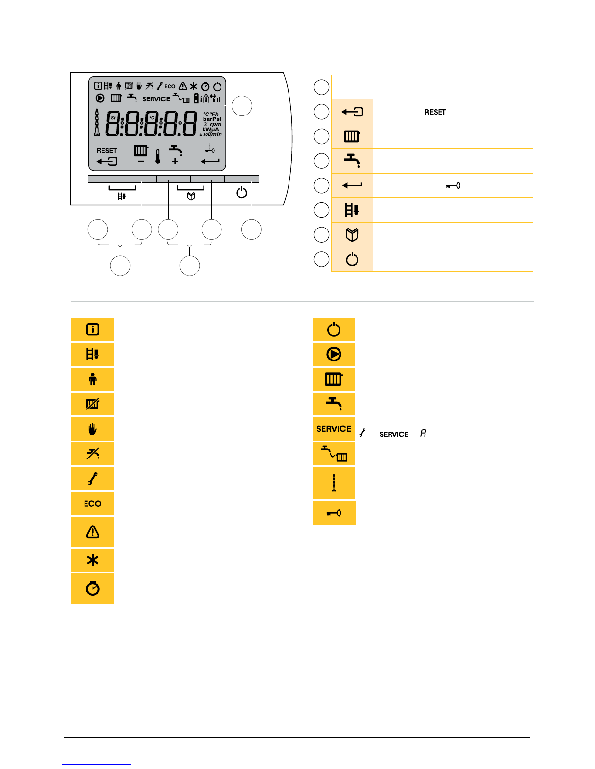
2.1 Control Panel
1
Display
2
[Escape] or button
3
Heating temperature or [-] button
4
DHW temperature or [+] button
5
[Enter] or cancel lock-out button
6
Setup buttons (press the 2 and 3
buttons simultaneously)
7
[Menu] buttons (press the 4 and 5
buttons simultaneously)
8
ON/OFF switch
1
2 3 4 5 8
6 7
Information menu:
Reading the various current values.
ON/OFF switch: After 5 lock-outs, the
boiler must be switched OFF/ON again.
Setup function active: either high or low
fire for CO
2
measurement.
Boiler pump: The pump operates.
User menu: Parameters at user level can
be changed.
Heating system function: Access to
heating system temperature parameter.
Heating program deactivated: The
heating mode is deactivated.
DHW function: Access to potable hot
water temperature parameter.
Manual mode:
Boiler is set to manual operation.
Yellow display with the symbols:
+ + (Maintenance message).
DHW programme deactivated:
The DHW mode is deactivated.
Water pressure:
The water pressure is too low.
Service menu: Parameters at installer
level can be changed.
Energy-saving mode: The boiler will operate
to mantein a minimum temperature.
Fault:
Boiler indicates a fault. This is indicate from
the E code and red display.
Burner level: Indicate the flame is present
and the percentage of modulation in
incriments.
Frost protection:
Boiler is running in frost protection mode.
Hour counter menu: Readout of the
operating hours, number of successful
starts and hours on without power failure.
Symbols
Display functions
Locking the keys:
Front controller lock-out
is activated.

9
User Guide (en)
7703476.01 (1-03/18)
2.2 USER-LEVEL PARAMETERS
Parameters P1 to P8 can be adjusted by the enduser in order to meet the
heating system and DHW comfort needs.
CAUTION
Modication of the factory settings may be detrimental to the
operation of the boiler.
• Press the two Menu buttons simultaneously and then the (+) button
until the symbol ashes on the menu bar.
• Select the user menu using the
button,(P1) button is displayed with
the "1" ashing.
• Press the button
a second time, the central heating supply temperature
value appears and ashes. e.g. 170 °F.
• Change the value by pressing the (-) button or (+) button. In this example
using button (-) to (140°F).
• Conrm the value with the
button, (P1) is displayed with "1" ashing.
• Press the
button 2 times to return to the current operating mode.
Parameter Description Adjustment range
Factory setting
1.70 1.110
P1
Max supply temperature for the CH mode
(Set temperature)
68 to 176ºF
20 to 80ºC
176°F/80°C
P2
Max DHW temperature set point
104 to 149ºF
40 to 65 ºC
140ºF/60ºC
P3
Switch on/off CH/DHW function
0 = Heating off / DHW off
1 = Heating on / DHW on
2 = Heating on / DHW off
3 = Heating off / DHW on
2
P4
Pre-heating a DHW plate exchanger
0 = Always on
1 = Always off
2 = Controller
2
P5
On/off thermostat anticipator
0 = No
1 = Yes
0
P6
Type of information on display
0 = Simple
1 = Extended
2 = Automatic
3 = Automatic + Key lock
1
P7
Pump post run time CH
1 to 98 minutes
99 minutes = continuous
3
P8
Display brightness when backlight is active
0 = Low
1 = High
1
1x
2x
7703476.01 (1-03/18)
10
User Guide (en)
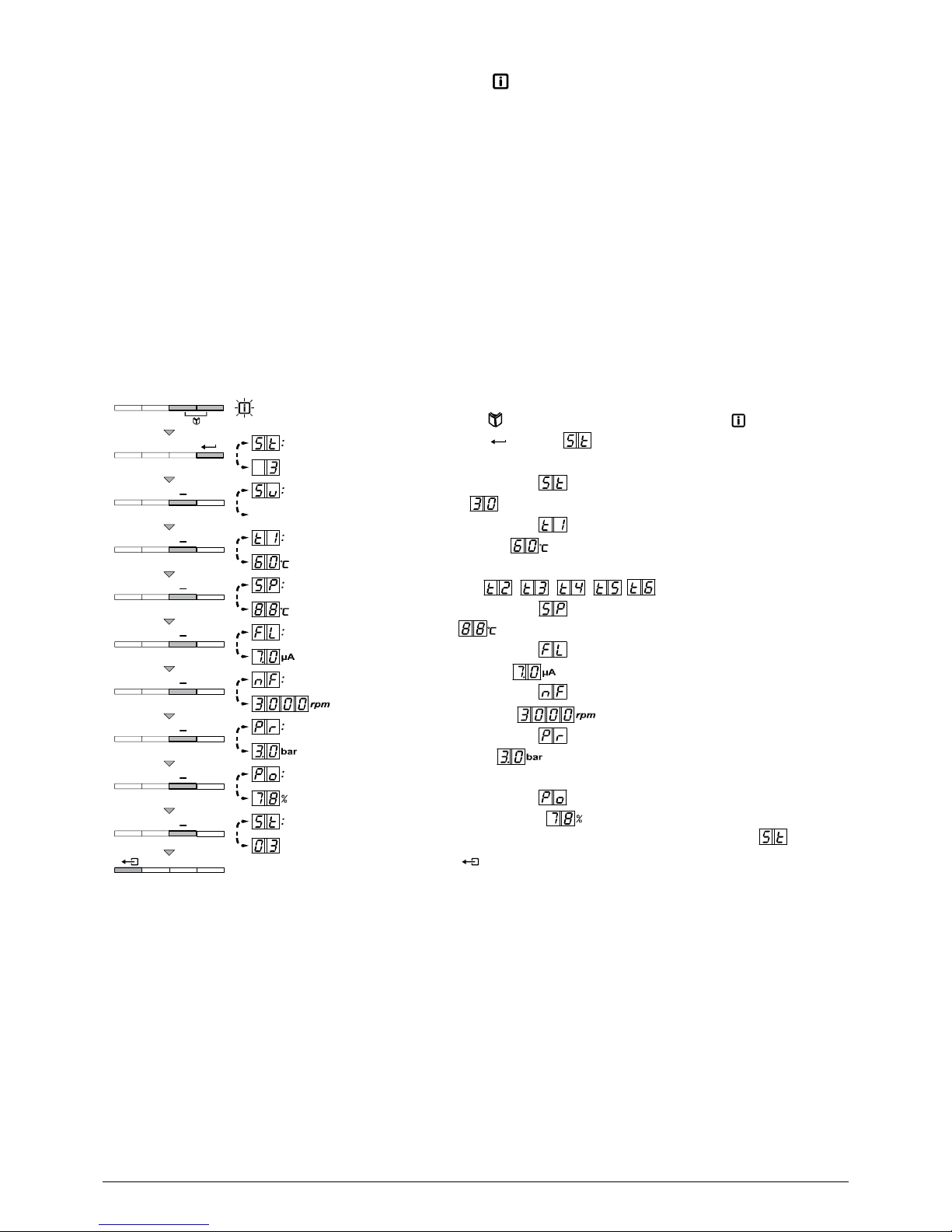
2.2.1 READING MEASURED VALUES
The following current values can be read off the information menu :
• St = State
• Su = Sub-status
• t1 = Supply temperature ºF/ºC
• t2 = Return temperature ºF/ºC
• t3 = DHW tank temperature ºF/ºC
• t4 = Outdoor temperature ºF/ºC (Only with an outdoor temperature sensor: Optional)
• t5 = Solar boiler temperature ºF/ºC
• t6 = Flue gas tempreature ºF/ºC
• Sp = Internal set point ºF/ºC
• Fl = Ionization current (μA)
• ñf = Fan speed in rpm
• Pr = Water pressure psig/bar
• Po = Supplied relative heat output (%).
The current values can be read as follows:
1.
2.
Press the two
Confirm using
buttons simultaneously. The symbol flashes.
button . is displayed, alternating with the
current status 3 (for example).
3. Press the [+] button. is displayed, alternating with the current
sub-status (for example).
4. Press the [+] button. is displayed, alternating with the current
flow temperature (for example).
5. Press the [+] button successively to scroll down to the various
parameters. ,
, , ,
4x
6. Press the [+] button. is displayed, alternating with the internal
set point (for example).
7. Press the [+] button. is displayed, alternating with the current
ionization current (for example).
8. Press the [+] button. is displayed, alternating with the current
fan rotation speed (for example).
9. Press the [+] button. is displayed, alternating with the current
water pressure (for example).
10. Press the [+] button. is displayed, alternating with the current
modulation percentage (for example).
11. Press the [+] button. The readout cycle starts again with .
12. Press the button 2 times to return to the current operating
mode.
2x
 Loading...