

Baxi Luna 3 Avant, Luna 3 Avant 240 Fi, Luna 3 Avant 310 Fi Instructions For The User And The Installer
Page 1

GB
Instructions for the User and the Installer
HU
CZ
Felszerelési és használati utasítás
Návod na použití pro uživatele a instalatéry
Plynové závěsné kotle s vysokou účinností
Page 2
GB
HU
CZ
Dear Customer,
We are sure your new boiler will comply with all your requirements.
Purchasing one of the Westen products satisfi es your ex pectations: good functioning, simplicity and ease of
use.
Do not dispose of this booklet without reading it: you can fi nd here some very useful information, which will
help you to run your boiler correctly and effi ciently.
Do not leave any parts of the packaging (plastic bags, polystyrene, etc.) within children’s reach as they are a potential
source of danger.
Westen boilers bear the CE mark in compliance with the basic requirements as laid
down in the following Directives:
- Gas Directive 90/396/CEE
- Performance Directive 92/42/CEE
- Electromagnetic Compatibility Directive 89/336/CEE
- Low Voltage Directive 73/23/CEE
Westen, one of the leading European enterprises to produce central heating and hot water devices for domestic use (wall-mounted gasoperated boilers, fl oor-standing boilers and electrical water-heaters) has obtained the CSQ certifi cate of conformity to the UNI EN ISO 9001
norms. This certifi cate guarantees that the Quality System applied at the Westen factory in Bassano del Grappa, where your boiler was
produced, meets the standards of the UNI EN ISO 9001 norm, which is the strictest and concerns all organization stages and operating
personnel involved in the production and distribution processes.
CONTENTS
ISTRUCTIONS PERTAINING TO THE USER
1. Instructions prior to installation 3
2. Instructions prior to commissioning 3
3. Commissioning of the boiler 4
4. Central Heating (CH) and Domestic Hot Water (D.H.W.) temperature adjustment 5
5. Filling the boiler 6
6. Turning off the boiler 6
7. Gas change 6
8. Prolonged standstill of the system. frost protection 6
9. Error messages and table of faults 7
10. Servicing instructions 7
ISTRUCTIONS PERTAINING TO THE INSTALLER
11. General information 8
12. Instructions prior to installation 8
13. Boiler installation 9
14. Boiler size 9
15. Installation of fl ue and air ducts 10
16. Connecting the mains supply 14
17. Fitting a room thermostat 15
18. Gas change modalities 15
19. Information display 17
20. Parameters setting 19
21. Control and operation devices 20
22. Positioning of the ignition and fl ame sensing electrode 21
23. Check of combustion parameters 21
24. Output / pump head performances 21
25. Connection of the external probe 22
26. Electrical connections to remote control device 22
27. Electrical connections to a zonal heating system 23
28. How to purge the DHW system from limestone deposits 24
29. How to disassemble the DHW heat exchanger 24
30. Cleaning the cold water fi lter 24
31. Boiler schematic 25
32. Illustrated wiring diagram 26
33. Technical data 27
BAXI - 925.200.1
925.492.2
2
INSTRUCTIONS PERTAINING TO THE USER
Page 3

1. INSTRUCTIONS PRIOR TO INSTALLATION
GB
This boiler is designed to heat water at a lower than boiling temperature at atmospheric pressure. The boiler must be connected to a central heating system and to a domestic hot water supply system in compliance with its performances and
output power.
Have the boiler installed by a Qualifi ed Service Engineer and ensure the following operations are accomplished:
a) careful checking that the boiler is fi t for operation with the type of gas available. For more details see the notice on the
packaging and the label on the appliance itself.
b) careful checking that the fl ue terminal draft is appropriate; that the terminal is not obstructed and that no other appliance
exhaust gases are expelled through the same fl ue duct, unless the fl ue is especially designed to collect the exhaust gas
coming from more than one appliance, in conformity with the laws and regulations in force.
c) careful checking that, in case the fl ue has been connected to pre-existing fl ue ducts, thorough cleaning has been carried
out in that residual combustion products may come off during operation of the boiler and obstruct the fl ue duct.
d) to ensure correct operation of the appliance and avoid invalidating the guarantee, observe the following precautions:
1. Hot water circuit:
1.1. If the water hardness is greater than 20 °F (1 °F = 10 mg calcium carbonate per litre of water) a polyphosphate or
comparable treatment system responding to current regulations.
1.2. Domestic Hot Water circuit must be thoroughly fl ushed after the installation of the appliance and before its use.
2. Heating circuit
2.1. new system
Before proceeding with installation of the boiler, the system must be cleaned and fl ushed out thoroughly to elimi-
nate residual thread-cutting swarf, solder and solvents if any, using suitable proprietary products. To avoid damaging metal, plastic and rubber parts, use only neutral cleaners, i.e. non-acid and non alkaline. The recommended
products for cleaning are: SENTINEL X300 or X400 and FERNOX heating circuit restore. To use this product proceeding strictly in accordance with the maker’s directions.
HU
CZ
2.2. existing system
Before proceeding with installation of the boiler, the system must be cleaned and fl ushed out to remove sludge and
contaminants, using suitable proprietary products as described in section 2.1. To avoid damaging metal, plastic
and rubber parts, use only neutral cleaners, i.e. non-acid and non-alkaline such as SENTINEL X100 and FERNOX
heating circuit protective. To use this product proceeding strictly in accordance with the maker’s directions. Remember that the presence of foreign matter in the heating system can adversely affect the operation of the boiler
(e.g. overheating and noisy operation of the heat exchanger).
Failure to observe the above will render the guarantee null and void.
2. INSTRUCTIONS PRIOR TO COMMISSIONING
Initial lighting of the boiler must be carried out by a licensed technician. Ensure the following operations are carried out:
a) compliance of boiler parameters with (electricity, water, gas) supply systems settings.
b) compliance of installation with the laws and regulations in force.
c) appropriate connection to the power supply and grounding of the appliance.
Failure to observe the above will render the guarantee null and void.
Prior to commissioning remove the protective plastic coating from the unit. Do not use any tools or abrasive detergents as
you may spoil the painted surfaces.
925.492.2
BAXI - 925.200.1
3
INSTRUCTIONS PERTAINING TO THE USER
Page 4
GB
3. COMMISSIONING OF THE BOILER
HU
CZ
To correctly light the boiler proceed as follows:
• Provide power supply to the boiler.
• open the gas cock;
• press the
Note: if summertime mode is setting, the boiler will light only during a D.H.W. demand.
• To adjust the CH and D.H.W. temperature, press the +/- respective buttons as described in section 4.
Warning: During initial lighting, until the air contained in the gas pipes is not released, the burner may fail to light immediately and that may cause a ‘blockage’ of the boiler. Under such circumstances we recommend you to repeat the ignition
procedure until the gas is delivered to the burner, and press
button, for at least two seconds, to set the operating boiler mode (see section 3.2)
button for at least 2 seconds.
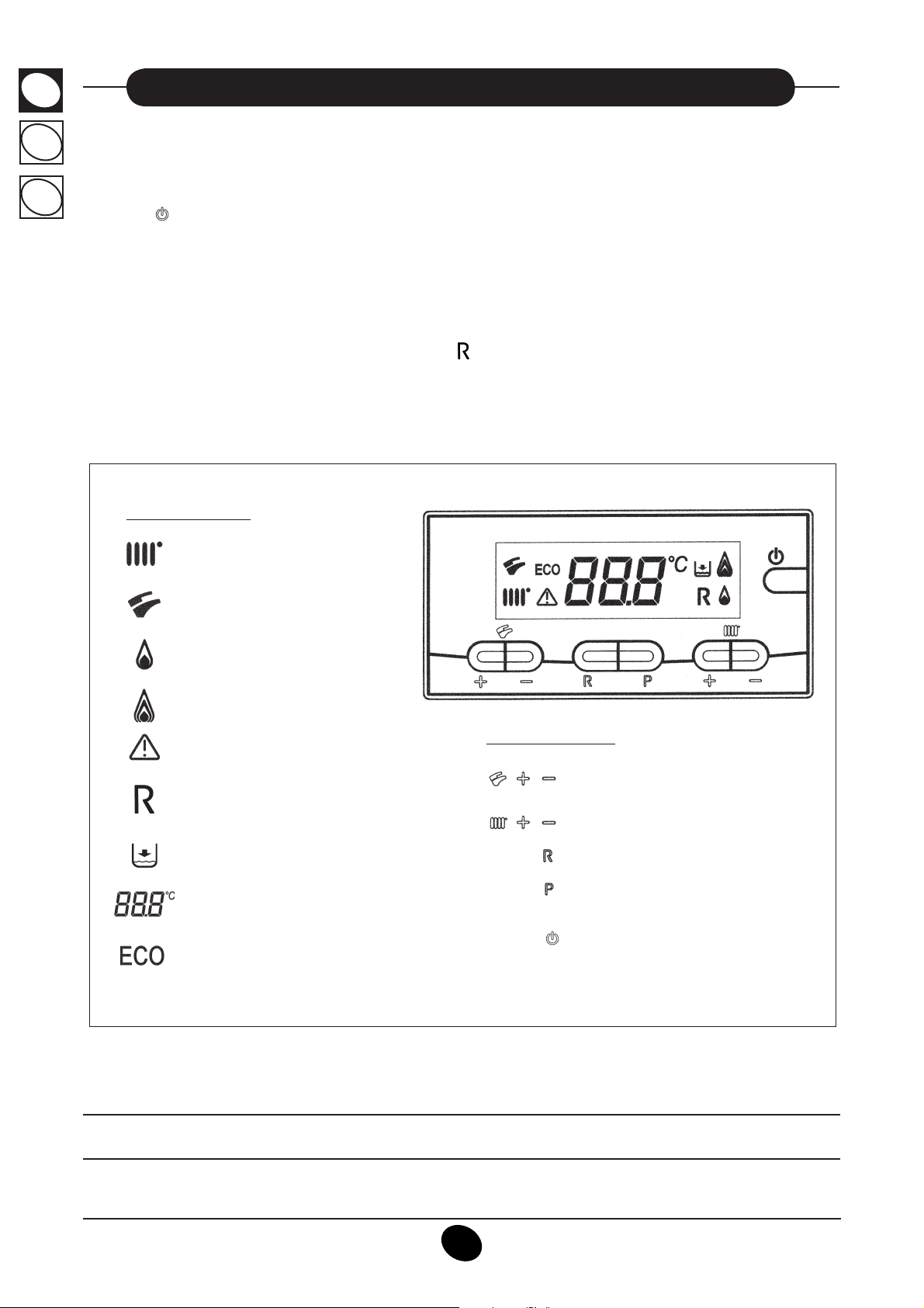
DISPLAY LEGEND:
Operating in
Central Heating mode (CH)
_90602103
Operating in Domestic
Hot Water mode (D.H.W.)
Flame present - power level = 25%
(burner switch on)
Boiler power levels
(3 power levels)
Generic ERROR
RESET
Water pressure LOW
Numeric signalling
(temperature, error codes, etc)
FUNCTION ACTIVATED
(see Section 4)
BUTTONS LEGEND
D.H.W. temperature regulation
Central Heating (CH)
RESET
ECO - COMFORT
MODE BUTTON
(see section 3.2)
temperature regulation
Figure 1
If the optional remote control device is connected, adjust the boiler using this device. See the instructions accompanying this accessory item.
BAXI - 925.200.1
925.492.2
INSTRUCTIONS PERTAINING TO THE USER
4
Page 5

3.1 SYMBOL MEANING
GB
There are 4 power levels displayed during boiler operation
regarding the gas boiler modulation, as shown in fi gure 2:
Figure 2
3.2 DESCRIPTION OF BUTTON (SUMMER - WINTER - HEATING ONLY - OFF)
10
11_
50
6
0
Press this button to set the following operating modes:
• SUMMER
• WINTER
• HEATING ONLY
• OFF
In the SUMMER mode, the display shows
. The boiler satisfi es requests for domestic hot water only while central heat-
ing is NOT enabled (ambient antifreeze function active).
In the WINTER mode, the display shows and . The boiler satisfi es requests for both domestic hot water and central
heating (ambient antifreeze function active).
HU
CZ
In the HEATING ONLY mode, the display shows
. The boiler satisfi es requests for central heating only (ambient anti-
freeze function active).
In the OFF mode, the display shows neither of the above two symbols
. In this mode, only the ambient antifreeze
function is active while requests for domestic hot water and central heating are not satisfi ed.
4. CENTRAL HEATING (CH) AND DOMESTIC HOT WATER (D.H.W.) TEMPERATURE ADJUSTMENT
The CH and D.H.W. temperature adjustment are carried out by pressing the relative +/- buttons (fi gure 1).
When the burner is lighted the display shows the symbol
CENTRAL HEATING (CH)
The system must be equipped with a room thermostat (see the relevant regulations) to control the temperature in the
rooms.
During a CH mode, the display shows a CH blinking symbol and the CH fl ow temperature value (°C).
DOMESTIC HOT WATER (D.H.W.)
During a D.H.W. request, the display shows a D.H.W. blinking symbol and the D.H.W. fl ow temperature value (°C).
There are two different setpoint which can be quickly set: ECO and COMFORT.
To adjust the temperature values, proceed as follows:
ECO
The ECO temperature setpoint allows the user to quickly set the relative domestic hot water temperature pressing the P
button. In eco function the display reads out “eco”. To set the ECO temperature setpoint press the +/-
.
buttons.
COMFORT
The COMFORT temperature setpoint allow the user to quickly set the relative domestic hot water temperature pressing
the P button. To set the COMFORT temperature setpoint press the +/-
925.492.2
BAXI - 925.200.1
5
buttons.
INSTRUCTIONS PERTAINING TO THE USER
Page 6

GB
5. FILLING THE BOILER
HU
CZ
IMPORTANT: Regularly check that the pressure displayed by the pressostat (fi gure 3) is 0.7 to 1.5 bar, with boiler not op-
erating. In case of overpressure, open the boiler drain valve.
In case the pressure is lower open the boiler fi lling tap.
We recommend you open the tap very slowly in order to let off the air.
During this operation, the gas boiler must be in “OFF” mode (press the
Filling tap
M anometer
0 3 1 _ 3 0 6 0 2 / C 1 9 7 1 _ G
Figure 3
D rain point
button - See section 3.2).
6. TURNING OFF THE BOILER
The electric supply to the boiler must be removed in order to switch it OFF.
With the gas boiler in “OFF” mode (section 3.2), the display reads out “OFF” but the main board is still supplied.
7. GAS CHANGE
These boilers set for natural gas can be converted to work with LPG.
Any gas change must be effected by a Qualifi ed Service Engineer.
8. PROLONGED STANDSTILL OF THE SYSTEM. FROST PROTECTION
We recommend you avoid draining the whole system as water replacements engender purposeless and harmful limestone
deposits inside the boiler and on the heating elements. In case the boiler is not operated during wintertime and is therefore
exposed to danger of frost we suggest you add some specifi c-purpose anti-freeze to the water contained in the system
(e.g.: propylene glycole coupled with corrosion and scaling inhibitors).
The electronic management of boilers includes a “frost protection” function in the central heating system which operates
the burner to reach a heating fl ow temperature of 30° C when the system heating fl ow temperature drops below 5°C.
The frost protection function is enabled if:
* electrical supply to the boiler is on;
* the gas service cock is open;
* the system pressure is as required;
* the boiler is not blocked.
BAXI - 925.200.1
925.492.2
6
INSTRUCTIONS PERTAINING TO THE USER
Page 7
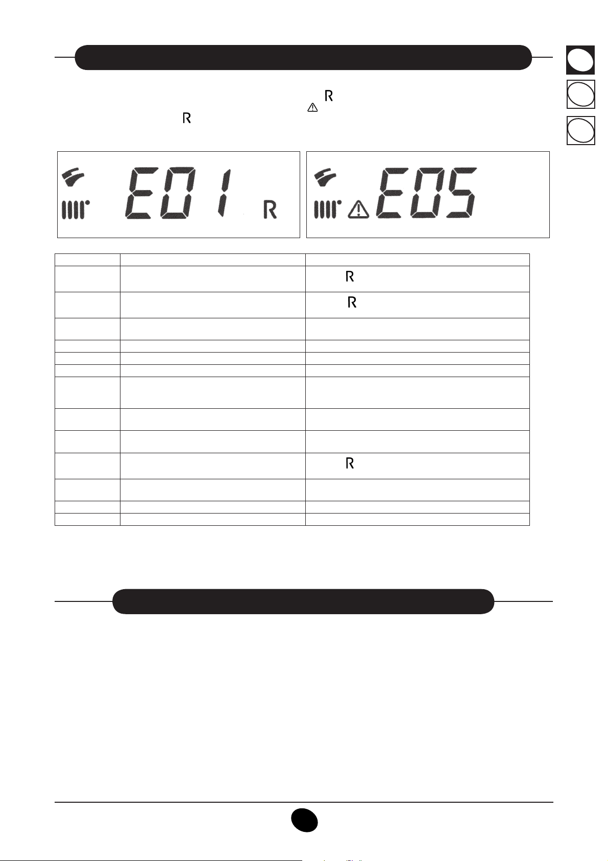
9. ERROR MESSAGES AND TABLE OF FAULTS
GB
The anomalies are carried out on the display with an error code (e.g. E01).
The anomalies which can be reset by the user are shown with the
The anomalies which cannot be reset are carried out with the
To RESET the gas boiler, press
Figure 4
ERROR CODE Description of FAULTS CORRECTIVE ACTION
E01
E02
E03
E04
E05
E06
E10
E11
E25
E35
E97
E98
E99
Gas supply fault
Safety thermostat sensor tripped
Flue thermostat sensor tripped / Flue pressure
switch tripped
Safety error due to frequent fl ame loss Call an authorised Service centre.
Central heating NTC sensor fault Call an authorised Service centre.
Domestic Hot Water NTC sensor fault Call an authorised Service centre.
Water pressure LOW
Safety thermostat for low temperature system
cuts in (if connected)
Boiler max temperature exceeded (probable
pump jammed)
Fault fl ame (parasitic fl ame)
Electronic board input frequency (Hz) incorrectly
set
Internal card error Call an authorised Service centre.
Internal card error Call an authorised Service centre.
button for at least 2 seconds.
6 0 1 1 _ 5 0 6 0
symbol (e.g. fi gure 4).
symbol (e.g. fi gure 4.1).
Figure 4.1
Press the button (fi gure 1) for at least 2 seconds. If this
fault persist, call an authorised Service centre.
Press the
fault persist, call an authorised Service centre.
Call an authorised Service centre.
Check that the pressure in the system is as specifi ed. See
Section 5. If this fault persist, call an authorised Service centre.
Call an authorised Service centre.
Call an authorized Service centre.
Press the
fault persists, call an authorized Service centre
Change the frequency (Hz) setting.
button (fi gure 1) for at least 2 seconds. If this
button (fi gure 1) for at least 2 seconds. If this
HU
CZ
7 0 1 1 _ 5 0 6 0
Note: when an anomaly occurs, the display background fl ashes with the error code.
10. SERVICING INSTRUCTIONS
To maintain effi cient and safe operation of your boiler have it checked by a Qualifi ed Service Engineer at the end of every
operating period.
Careful servicing will ensure economical operation of the system.
Do not clean the outer casing of the appliance with abrasive, aggressive and/or easily fl ammable cleaners (i.e.: gasoline,
alcohol, and so on). Always isolate the electrical supply to the appliance before cleaning it (see section 6).
925.492.2
BAXI - 925.200.1
7
INSTRUCTIONS PERTAINING TO THE USER
Page 8

GB
HU
CZ
11. GENERAL INFORMATION
The following remarks and instructions are addressed to Service Engineers to help them carry out a faultless installation.
Instructions regarding lighting and operation of the boiler are contained in the ‘Instructions pertaining to the user’ section.
Note that installation, maintenance and operation of the domestic gas appliances must be performed exclusively by qualifi ed personnel in compliance with current standards.
Please note the following:
* This boiler can be connected to any type of double- or single feeding pipe convector plates, radiators, thermoconvectors
Design the system sections as usual though taking into account the available output / pump head performances, as
shown in section 24.
* Do not leave any packaging components (plastic bags, polystyrene, etc.) within children’s reach as they are a potential-
source of danger.
* Initial lighting of the boiler must be effected by a Qualifi ed Service Engineer.
Failure to observe the above will render the guarantee null and void.potentielle Gefahrenquelle darstellt.
12. INSTRUCTIONS PRIOR TO INSTALLATION
This boiler is designed to heat water at a lower than boiling temperature at atmospheric pressure. The boiler must be connected to a central heating system and to a domestic hot water supply system in compliance with its performances and
output power.
Have the boiler installed by a Qualifi ed Service Engineer and ensure the following operations are accomplished:
a) careful checking that the boiler is fi t for operation with the type of gas available. For more details see the notice on the
packaging and the label on the appliance itself.
b) careful checking that the fl ue terminal draft is appropriate; that the terminal is not obstructed and that no other ap-
pliance exhaust gases are expelled through the same fl ue duct, unless the fl ue is especially designed to collect the
exhaust gas coming from more than one appliance, in conformity with the laws and regulations in force.
c) careful checking that, in case the fl ue has been connected to pre-existing fl ue ducts, thorough cleaning has been car-
ried out in that residual combustion products may come off during operation of the boiler and obstruct the fl ue duct.
To ensure correct operation of the appliance and avoid invalidating the guarantee, observe the following precautions:
1. Hot water circuit:
1.1. If the water hardness is greater than 20 °F (1° F = 10 mg calcium carbonate per litre of water) a polyphosphate or
comparable treatment system responding to current regulations.
1.2. Domestic Hot Water circuit must be thoroughly fl ushed after the installation of the appliance and before its use.
2. Heating circuit
2.1. new system
Before proceeding with installation of the boiler, the system must be cleaned and fl ushed out thoroughly to elimi-
nate residual thread-cutting swarf, solder and solvents if any, using suitable proprietary products.
To avoid damaging metal, plastic and rubber parts, use only neutral cleaners, i.e. non-acid and non alkaline. The
recommended products for cleaning are:
SENTINEL X300 or X400 and FERNOX heating circuit restore. To use this product proceeding strictly in accord-
ance with the maker’s directions.
2.2. existing system
Before proceeding with installation of the boiler, the system must be cleaned and fl ushed out to remove sludge and
contaminants, using suitable proprietary products as described in 2.1.
To avoid damaging metal, plastic and rubber parts, use only neutral cleaners, i.e. non-acid and non-alkaline such
as SENTINEL X100 and FERNOX heating circuit protective. To use this product proceeding strictly in accordancewith the maker’s directions.
Remember that the presence of foreign matter in the heating system can adversely affect the operation of the
boiler (e.g. overheating and noisy operation of the heat exchanger).
Failure to observe the above will render the guarantee null and void.
IMPORTANT: when connecting an instantaneous boiler (mixed) to a system with solar panels, the maximum temperature
of the DHW at the boiler inlet must not be greater than:
• 60°C with a fl ow limiting device
• 70°C without a fl ow limiting device
BAXI - 925.200.1
925.492.2
INSTRUCTIONS PERTAINING TO THE INSTALLER
8
Page 9
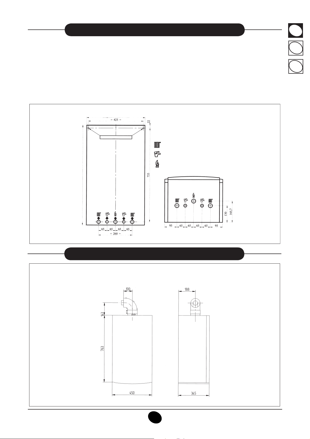
13. BOILER INSTALLATION
Decide upon the boiler location, then tape the template on the wall. Connect the pipework to the gas and water inlets prea
ranged on the template lower bar. We suggest you fi t two G3/4 stop cocks (available on demand) on the central heating
system fl ow and return pipework; the cocks will allow to carry out important operations on the system without draining it
completely. If you are either installing the boiler on a pre-existent system or substituting it, we suggest you also fi t settling
tank on the system return pipework and under the boiler to collect the deposits and scaling which may remain
and be circulated in the system after the purge.
When the boiler is fi xed on the template connect the fl ue and air ducts (fi ttings supplied by the manufacturer) according to
the instructions given in the following sections.
GB
HU
CZ
Figure 5
= BOILER WIDTH 450 =
1502 /4050_C9671G
BOILER CONNECTION POINTS
240 Fi - 240 i - 310 Fi
: G3/4 heating flow / return
: G1/2 domestic hot water inlet / outlet
087
TH
GI
E
H
RELIOB
: G3/4 gas inlet to the boiler
0512_0505/CG1769
14. BOILER SIZE
Figure 6
BAXI - 925.200.1
925.492.2
240 Fi - 310 Fi - 1.240 Fi - 1.310 Fi
omi
n
im
_
6 0
6 0 2 2
9
3
06
2
_
6
06
0
INSTRUCTIONS PERTAINING TO THE INSTALLER
Page 10

GB
15. INSTALLATION OF FLUE AND AIR DUCTS
HU
CZ
Models 240 Fi - 310 Fi - 1.240 Fi - 1.310 Fi
We guarantee ease and fl exibility of installation for a gasfi red forced draught boiler thanks to the fi ttings and fi xtures
supplied (described below).
The boiler is especially designed for connection to an exhaust fl ue / air ducting, with either coaxial, vertical or horizontal terminal. By means of a splitting kit a two-pipe system may also be installed.
Exclusively install fi ttings supplied by the manufacturer.
CAUTION: To enhance operating safety, make sure
the fl ue ducts are fi rmly fi xed to the wall with suitable
brackets.
Figure 7
COAXIAL FLUE - AIR DUCT (CONCENTRIC)
This type of duct allows to disengage exhaust gases and to draw combustion air both outside the building and in case a
LAS fl ue is fi tted.
The 90° coaxial bend allows to connect the boiler to a fl ue-air duct in any direction as it can rotate by 360°. It can more ver
be used as a supplementary bend and be coupled with a coaxial duct or a 45° bend.
/5090_3050C8361G
Figure 8
If the fl ue outlet is placed outside, the fl ue-air ducting must
protrude at least 18mm out of the wall to allow alluminium
CG_0886
weathering tile to be fi tted and sealed to avoid water leakages.
Ensure a minimum upward slope of 1 cm towards the outside
per each metre of duct length.
• A 90° bend reduces the total duct length by 1 metre.
• A 45° bend reduces the total duct length by 0.5 metre.
• The fi rst 90° bend is not included in the maximum avail
able length.
15.1 HORIZONTAL FLUE TERMINAL INSTALLATION OPTIONS
L max = 4 m 240 Fi
L max = 4 m
L max = 3 m 310 Fi
BAXI - 925.200.1
925.492.2
L max = 3 m 240 Fi
L max = 3 m
L max = 2 m 310 Fi
10
_2 100
2
150
INSTRUCTIONS PERTAINING TO THE INSTALLER
Page 11

15.2 LAS FLUE DUCT INSTALLATION OPTIONS
1 5 0 2 _ 2 0 0 2
L max = 4 m 240 Fi
L max = 4 m
L max = 3 m 310 Fi
15.3 VERTICAL FLUE TERMINAL INSTALLATION OPTIONS
This type of installation can be carried out both on a fl at or pitched roof by fi tting a terminal, an appropriate weathering tile
and sleeve, (supplementary fi ttings supplied on demand).
1
4 6
1 G C
/
8 0
9 0 _
3 0
5 0
GB
HU
CZ
L max = 4 m L max = 2 m L max = 3 m
For detailed instructions concerning the installation of fi ttings refer to the technical data accompanying the fi ttings.
SEPARATED FLUE-AIR DUCTING
This type of ducting allows to disengage exhaust fl ue gases both outside the building and into single fl ue ducts.
Comburant air may be drawn in at a different site from where the fl ue terminal is located.
The splitting kit consists of a fl ue duct adaptor (100/80) and of an air duct adaptor.
For the air duct adaptor fi t the screws and seals previously removed from the cap.
The fl ue duct must not fall and all horizontal runs must always rise at approximately 3° from the boiler.
Consideration for protection to exposed parts of the outlet duct where accidental touch may occur must be given.
Calculation of the total equivalent length:
The total equivalent length depends on the number and type of components in the fl ue system.
The total equivalent length is the addition of Air Duct Value + Flue Duct Value, plus the equivalent length of any bends.
The bend equivalences are:
45° = 0.25m
90° = 0.50m
ASSEMBLING THE FLUE SYSTEM
The pipe extensions can be cut to length if necessary. The cut end should be de-burred to prevent damage to seals when
assembling to a fi tting.
Apply soap solution to all seals to aid assembly.
Always use 80mm pipe clamps to secure/support the ducts. Secure the roof terminal with the pipe clamp supplied.
BAXI - 925.200.1
925.492.2
11
INSTRUCTIONS PERTAINING TO THE INSTALLER
Page 12

GB
IMPORTANT: If the fl ue system is to be fi tted prior to the boiler, temporary precautions must be taken to prevent
rain entry into the room of installation. Any precautionary measures must be removed prior to fi tting the boiler.
HU
CZ
Flue Duct Adaptor
Engage the fl ue duct adaptor on the boiler adaptor, making sure that it is pushed down as far as possible.
Air Duct Adaptor
Undo the screws securing the blanking plate to the boiler top panel. Discard the plate.
There is a restrictor plate supplied in the kit with the gas boiler. This restrictor is used either way up depending upon model
of boiler - see fi gure 9.
IMPORTANT: The restrictor MUST be positioned as shown in the diagrams below.
Take one of the gaskets supplied in the kit and place on the boiler top panel.
Align the appropriate restrictor as shown. Position the second gasket over the restrictor.
Using the screws previously removed secure the air duct adaptor to the top panel.
Continue to fi t the twin fl ue system.
Position of Restrictor model 240 Fi Position of Restrictor model 310 Fi
Figure 9a
Figure 9a
Blanking Plate
Flue Duct
Adaptor
Figure 9b
Air Duct
Adaptor
Gasket
Restrictor
Gasket
BoilerAdaptor
Figure 9b
BAXI - 925.200.1
925.492.2
12
INSTRUCTIONS PERTAINING TO THE INSTALLER
Page 13

15.4 SPLIT FLUE OVERALL DIMENSIONS
GB
HU
0504_1806/CG_1794
15.5 SEPARATED HORIZONTAL FLUE TERMINALS INSTALLATION OPTIONS
IMPORTANT: Ensure a minimum downward slope of 1 cm toward the outside per each metre of duct length.
In the event of installation of the condensate collection kit, the angle of the drain duct must be directed towards the boiler.
3
4 6 1 G
_ 3 0 5 0 2 2 / 1 0 C
CZ
L max = 10 m 240 Fi
L max = 8 m 310 Fi
L max = 10 m
(L1 + L2) max = 30 m 240 Fi
(L1 + L2) max = 30 m
(L1 + L2) max = 25 m 240 Fi
NB: For C52 types, terminals for combustion air suction and combustion product extraction must never be fi tted on opposite walls of the building.
The maximum length of the suction duct must be 10 metres.
If the fl ue duct exceeds 6 m, the condensate collection kit (supplied as an accessory) must be fi tted close to the boiler.
15.6 SEPARATED VERTICAL FLUE TERMINALS INSTALLATION OPTIONS
4 4 6
1
G
C
/ 1 1 9 0 _ 3 0 5 0
L max = 10 m
L max = 10 m
L max = 10 m
BAXI - 925.200.1
925.492.2
13
INSTRUCTIONS PERTAINING TO THE INSTALLER
Page 14

GB
HU
Important: if fi tting a single exhaust fl ue duct, ensure it is adequately insulated (e.g.: with glass wool) wherever the duct
passes through building walls.
For detailed instructions concerning the installation of fi ttings refer to the technical data accompanying the fi ttings.
CZ
16. CONNECTING THE MAINS SUPPLY
Electrical safety of the appliance is only guaranteed by correct grounding, in compliance with the applicable laws and
regulations.
Connect the boiler to a 230V monophase + ground power supply by means of the three-pin cable supplied with it and make
sure you connect polarities correctly.
Use a double-pole switch with a contact separation of at least 3mm in both poles.
In case you replace the power supply cable fi t a HAR H05 VV-F’ 3x0.75mm
…Access to the power supply terminal block
• isolate the electrical supply to the boiler by the double-pole switch;
• unscrew the two screws securing the control board to the boiler;
• rotate the control board;
• unscrew the lid and gain access to the wiring (Figure 10).
The 2A fast-blowing fuses are incorporated in the power supply terminal block (to check or replace the fuse, pull out the
black fuse carrier).
IMPORTANT : be sure to connect polarities correctly L (LIVE) - N (NEUTRAL).
(L) = Live (brown)
(N) = Neutral (blue)
(
) = Ground (yellow/green)
(1) (2) = Room thermostat terminal
2
cable with an 8mm diameter max.
077
1
G
C
0
50_
1502 /8
Figure 10
CAUTION: If the appliance is directly connected to a underfl oor system, the fi tter must install a safety thermostat
to prevent it from overheating.
BAXI - 925.200.1
925.492.2
14
INSTRUCTIONS PERTAINING TO THE INSTALLER
Page 15

17. FITTING A ROOM THERMOSTAT
GB
To connect the room thermostat to the boiler terminal block, proceed as follows:
• reach the power supply terminal block (fi gure 10);
• connect the room thermostat to the terminals (1) - (2) and remove the jumper.
18. GAS CHANGE MODALITIES
A Qualifi ed Service Engineer may adapt this boiler to operate with natural gas (G. 20) or with liquid gas (G. 31).
The procedure for calibrating the pressure regulator may vary according to the type of gas valve fi tted (honeywell or SIT;
see fi gure 11).
Carry out the following operations in the given sequence:
Honeywell valve
A) Substitute the main burner injectors
• carefully pull the main burner off its seat;
• substitute the main burner injectors and make sure you
tighten them to avoid leakage. The nozzle diameters are
specifi ed in table 1.
B) Change the modulator voltage
• setting F02 parameter according to the gas used as described in section 20.
mod. VK 4105 M
HU
CZ
C) Pressure adjusting device setting
• connect the positive pressure test point of a differential
(possibly water-operated) manometer to the gas valve
pressure test point (Pb) (Figure 11); connect, for sealed
chamber models only, the negative pressure test point of
the manometer to a “T” fi tting in order to join the boiler
adjusting outlet, the gas valve adjusting outlet (Pc) and the
manometer. (The same measurement can be carried out
by connecting the manometer to the pressure test point
(Pb) after removing the sealed chamber front panel); If you
measure the pressure of burners in a different way you
may obtain an altered result in that the low pressure created in the sealed chamber by the fan would not be taken
into account.
C1) Adjustment to nominal heat output
• open the gas tap;
• press
(section 3.2);
• open a hot water tap to reach a minimum 10 l/min fl ow rate
or ensure that maximum heating requirements are set;
• remove the modulator cover;
• adjust the tube brass screw (a) Fig. 12 to obtain the presure settings shown in table 1;
• check that boiler feeding dynamic pressure, as measured
at the inlet gas valve pressure test point (Pa) (Figure 11) is
correct (37 mbar for propane gas G.31, 20 mbar for natural
gas G20);
button (fi gure 1) and set the boiler in winter mode
Pc
Pa
70
02 6040_
SIT valve
mod. SIGMA 845
Pb
1
992220051
BAXI - 925.200.1
925.492.2
Figure 11
INSTRUCTIONS PERTAINING TO THE INSTALLER
15
Page 16

GB
HU
C2) Adjustment to reduced heat output
• disconnect the modulator feeding cable and unscrew the (b) Fig. 12 screw to reach the pressure setting corresponding
to reduced heat output (see table 1);
• connect the cable again;
• fi t the modulator cover and seal.
CZ
C3) Final checks
• apply the additional dataplate, specifying the type of gas and settings applied.
Honeywell gas valve Sit gas valve
107
1_
5060
Figure 12
a
b
05
1_
50
6
02
Table of burner pressures - heat output - burner injectors
240 Fi 310 Fi
Gas used G20 G31 G20 G31
Burner pressure (mbar*)
MINIMUM HEAT OUTPUT
Burner pressure (mbar*)
MAXIMUM HEAT OUTPUT
2,0 4,4 12,1 32,3
10,2 21,8 2,1 5,2
Injector diameter (mm) 1,18 0,77 1,25 0,77
no. of injectors 15
Table 1
Consumption table
Consumption 15 °C - 1013 mbar
Maximum heat output
Minimum heat output
p.c.i.
2,62 m
1,12 m3/h 0,92 Kg/h 1,26 m3/h 0,48 Kg/h
34,02 MJ/m
240 Fi 310 Fi
G20 G31 G20 G31
3
/h 1,92 Kg/h 3,22 m3/h 2,37 Kg/h
3
46,30 MJ/Kg 34,02 MJ/m346,30 MJ/Kg
Table 2
BAXI - 925.200.1
925.492.2
16
INSTRUCTIONS PERTAINING TO THE INSTALLER
Page 17

19. INFORMATION DISPLAY
GB
19.1 FIRST DISPLAYED INFORMATION
To correct light the boiler, proceed as follows:
• Provide power supply to the boiler.
When the gas boiler is power supplì, the display shows the following information:
1. all symbols alight;
2. manufacture information;
3. manufacture information;
4. manufacture information;
5. Type of boiler and gas used (eg. )
The displayed letters mean the following:
O
= natural boiler chamber
= natural gas METANE
n
6. Hydraulic system;
7. Software version (two numbers x.x);
• open the gas cock;
• press the
button, for at least two seconds, to set the operating boiler mode (see section 3.2).
Cn
= sealed boiler chamber
C
= LPG gas
L
HU
CZ
19.2 OPERATION INFORMATION
To display some useful information during the boiler operation proceed as follows:
• Press the (
value (e.g. fi gure 13);
) button for at least 6 seconds until the display shows “A00” (…“A07”) alternating with the respective
06
_0
16
026
Figure 13
BAXI - 925.200.1
925.492.2
17
INSTRUCTIONS PERTAINING TO THE INSTALLER
Page 18

GB
• Press the +/- domestic hot water buttons to display the following instantaneous information:
HU
CZ
A00: domestic hot water temperature value (°C);
A01: outside temperature (with external probe sensor connected);
A02: modulatine current value (100% = 230 mA METANE - 100% = 310 mA GPL);
A03: power range level value (%) - see parameter F13 (section 20);
A04: temperature setpoint value (°C);
A05: central heating fl ow temperature value (°C);
A06: fl ow water value (l/min x 10);
A07: fl ame signal value (8-100%).
Note: lines A08 and A09 are not used.
• This function is active for 3 minutes. To exit the function, press
button as described in section 3.2.
19.3 ANOMALIES DISPLAY
Note: the resetting operation is available only for 5 consecutive attempts, after which the RESET function is
disabled and the gas boiler remains blocked.
To carry out a new RESET attempt, proceed as follows:
• press the
• reset the boiler pressing the
• press the
button for at least 2 seconds;
button for at least 2 seconds, the display shows “OFF”;.
button for at least 2 seconds as describe in section 3.2.
See section 9 for error codes and anomalies description.
19.4 ADDITIONAL INFORMATION
For more detailed technical information, please consult the “SERVICE INSTRUCTIONS”.
BAXI - 925.200.1
925.492.2
18
INSTRUCTIONS PERTAINING TO THE INSTALLER
Page 19

20. PARAMETERS SETTING
To set the boiler parameters press the R and - buttons together for at least 6 seconds. When the function is activated,
the display shows “F01” alternated with the value of the parameter.
GB
HU
Parameters setting
• Press +/-
buttons for scrolling parameters;
• Press +/- buttons to change the single parameter value;
• Press the P button to save changes, the display shows
“MEM”;
• Press the
button to leave the function without saving, the
display shows “ESC”;
Description of parameter Default value
F01
F02
F03
F04
F05
F06
F07...F12
F13
F14
F15
F16
F17
F18
F19
F20
F21...F22
F23
F24
F25
F26...F29
F30
F31
F34...F41
Final parameter
Type of gas boiler
10 = sealed chamber
Type of gas
00 = natural (metane) - 01 = LPG
Hydraulic system
00 = instantaneous appliance
Programmable relay 1 setting
2 = zone system
Programmable relay 2 setting
13 = “cool” function for external air-conditioning
system (See SERVICE Instructions)
External sensor programmable input setting
(See SERVICE Instructions)
Manufacturer information 00
CH max. heating output (0-100%) 100
D.H.W. max. heating output (0-100%) 100
CH min. heating output (0-100%) 00
Maximum temperature setpoint setting
00 = 85°C - 01 = 45°C
Pump overrun time
(01-240 minutes)
Minimum burner pause
in central heating mode - 00=10 seconds
Manufacturer information 07
Manufacturer information --
Manufacturer information 00
Maximum D.H.W. setpoint 60
Manufacturer information 35
Lack of water safety device 00
Manufacturer information (read-only parameters) --
Manufacturer information 10
Manufacturer information 30
Diagnostics (See SERVICE Instructions) --
Calibration function activation (See SERVICE
Instructions)
(See SERVICE Instructions)
00
10
O 01
00
02
04
00
00
03
03
00
706
CZ
2
_
01
6
0
WARNING: do not modify the values of the “Manufacturer information” parameters.
BAXI - 925.200.1
925.492.2
19
INSTRUCTIONS PERTAINING TO THE INSTALLER
Page 20

GB
21. CONTROL AND OPERATION DEVICES
HU
CZ
The boiler has been designed in full compliance with European reference standards and in particular is equipped with the following:
• Air pressure switch for forced draught model (240Fi - 310 Fi)
This switch allows the burner to switch on provided the exhaust fl ue duct effi ciency is perfect.
In the event of one of the following faults:
• the fl ue terminal is obstructed;
• the venturi is obstructed;
• the fan is blocked;
• the connection between the venturi and the air pressure switch is interrupted;
The boiler will stay on stand-by and the display shows error code E03 (see section 9).
• Overheat safety thermostat
Thanks to a sensor placed on the heating fl ow, this thermostat interrupts the gas fl ow to the burner in case the water contained in the
primary circuit has overheated. Under such conditions the boiler is blocked and relighting will only be possible after the cause of the
anomaly has been removed.
It is forbidden to disenable this safety device
• Flame ionization detector
The fl ame sensing electrode, placed on the right of the burner, guarantees safety of operation in case of gas failure or incomplete inter-
lighting of the burner. The boiler is blocked after 3 relight attempt.
See section 9 to RESET normal operating conditions.
• Hydraulic pressure sensor
This device (3 - fi gure 20) enables the main burner only to be switched on if the system pressure is over 0.5 bars.
• Pump overrun for central heating circuit
The electronically-controlled supplementary running of the pump lasts 3 minutes (F17 - Section 20), when the boiler is in the central
heating mode, after the burner has switched off due to a room thermostat or intervention.
• Pump overrun for domestic hot water circuit
The electronic control system keeps the pump operating for 30 seconds in domestic hot water mode after the D.H.W. sensor has
switched off the burner.
• Frost protection device (central heating and domestic hot water systems)
Boilers electronic management includes a “frost protection” function in the central heating system which operates the burner to reach
a heating fl ow temperature of 30°C when the system heating fl ow temperature drops below 5 °C.
This function is enabled when the boiler is connected to electrical supply, the gas supply is on and the system pressure is as required.
• Lack of water circulation (probable pump jammed)
If the water inside the primary circuit doesn’t circulate, the display shows E25 error (see section 9).
• Anti-block pump function
In the event that no heat is required, the pump will automatically start up and operate for one minute during the following 24 hours. This
function is operative when the boiler is powered.
• Three-way anti-blockage valve
In the case of no heat is request for a period of 24 hours the three way valve carries out a complete commutation.
This function is operative when the boiler is powered.
• Hydraulic safety valve (heating circuit)
This device is set to 3 bar and is used for the heating circuit.
The safety valve should be connected to a siphoned drain. Use as a means of draining the heating circuit is strictly prohibited.
Note: domestic hot water is guaranteed even if the NTC sensor (5 - fi gure 20) is damaged. In this case, the temperature control is
carried out by the boiler fl ow temperature.
BAXI - 925.200.1
925.492.2
20
INSTRUCTIONS PERTAINING TO THE INSTALLER
Page 21

22. POSITIONING OF THE IGNITION AND FLAME SENSING ELECTRODE
7
0
1 9 9 2 0 0 1 0
Figure 14
23. CHECK OF COMBUSTION PARAMETERS
The boiler has two connection points specifi cally designed to allow technicians to measure the combustion effi ciency after installation and
ensure that the combustion products do not constitute a health risk.
One connection point is connected to the fl ue gas discharge circuit, and allows monitoring of the quality of the combustion products and
the combustion effi ciency.
The other is connected to the combustion air intake circuit, allowing checking of any recycling of the combustion products in case of
coaxial pipelines.
The following parameters can be measured at the connection point on the fl ue gas circuit:
• temperature of the combustion products;
• oxygen (O
• carbon monoxide (CO) concentration.
The combustion air temperature must be measured at the connection point on the air intake circuit, inserting the measur ement probe to
a depth of about 3 cm.
For natural draught boiler models, a hole must be made in the fl ue gas discharge pipe at a distance from the boiler equal to twice the inside
diameter of the pipe itself.
The following parameters can be measured through this hole:
• temperature of the combustion products;
• oxygen (O
• carbon monoxide (CO) concentration.
The combustion air temperature must be measured close to the point where the air enters the boiler.
The hole, which must be made by the person in charge of operating the system when it is commissioned, must be sealed
in a way which ensures that the combustion product discharge pipe is airtight during normal operation.
) or carbon dioxide (CO2) concentration;
2
) or carbon dioxide (CO2) concentration;
2
GB
HU
CZ
24. OUTPUT / PUMP HEAD PERFORMANCES
This is a high static head pump fi t for installation on any type of single or double-pipe heating systems. The air vent valve
incorporated in the pump allows quick venting of the heating system.
BAXI - 925.200.1
925.492.2
21
INSTRUCTIONS PERTAINING TO THE INSTALLER
Page 22

GB
HU
25. CONNECTION OF THE EXTERNAL PROBE
The boiler is prearranged for connection of an external probe (supplied as accessory).
For the connection, refer to the fi gure below and the instructions supplied with the probe.
CZ
Figure 15
Kt curves
CN 5
When the external probe is connected, the heating
circuit temperature control device regulates the dispersal coeffi cient
Kt. To set the curves (0…90) press the +/-
but-
tons.
NOTE: the maximum value of the fl ow temperature
TM depends on the F16 parameter setting (see sec-
tion 20). The
maximum fl ow temperature it may 85° or 45°C.
5
0 3 0 _
3
0 6
0
6 0
3 0 _
3
0 6
0
Graph 2
26. ELECTRICAL CONNECTIONS TO REMOTE CONTROL DEVICE
(SUPPLIED AS AN ACCESSORY)
The remote control device is not a standard
boiler component as it is su pplied as an
accessory. Open the electronic board and
connect the cable (supplied together with
the two-pin terminal board) to connector
CN7 on the electronic boiler board. Connect the terminals of the remote control
device to the two-pin terminal board (fi gure
16).
Graph 3
TM = flow temperature (°C)
T e = e x ternal temperature (°C)
CN 7
0610_1302 / CG_1856
BAXI - 925.200.1
925.492.2
Figure. 16
INSTRUCTIONS PERTAINING TO THE INSTALLER
22
Page 23

27. ELECTRICAL CONNECTIONS TO A ZONAL HEATING SYSTEM
GB
27.1 CONNECTING THE RELAY BOARD
The relay board is not a standard boiler component as it is supplied as an accessory. Connect terminals 1-2-3 (common
- normally closed - normally open) of connector Cn1 on the relay board to the respective terminals 10-9-8 on the boiler
terminal board M2 (fi gure 17).
BOILER BOARD
0610_0401 / CG_1840
RELAY BOARD ACCESSORY
RELAY 2
RELAY 1
HU
CZ
Figure 17
27.2 CONNECTING THE ZONES
Connect the contact relative to heating requests in zones that are not controlled by the remote control device in parallel to
terminals 1-2 “TA” on terminal board M1.
Remove the jumper.
The zone controlled by the remote control device is managed by the zone 1 solenoid, as illustrated in fi gure 18.
5
2
1
M1
ZONE 1
1
2
3
4
5
6
7
N.O.
8
N.C.
9
C
10
M2
ZONE 1
REMOTE CONTROL
SOLENOID
Elettrovalvola
ZONE 1
Zona 1
M
ZONE 2
(AMBIENT THERMOSTAT)
2
T.A.
M
E.V.2
RE2
ZONE 3
(AMBIENT THERMOSTAT)
3
T.A.
M
E.V.3
RE3
ZONE N
(AMBIENT THERMOSTAT)
L
n
T.A.
M
E.V.n
REn
N
2801 / CG_182
0607_
BAXI - 925.200.1
925.492.2
Figure 18
INSTRUCTIONS PERTAINING TO THE INSTALLER
23
Page 24

GB
28. HOW TO PURGE THE DHW SYSTEM FROM LIMESTONE DEPOSITS
HU
CZ
To clean the DHW system it is not necessary to remove the DHW heat exchanger if the assembly is equipped with the appropriate taps (supplied on demand) placed on the hot water outlet and inlet.
To carry out the purge it is necessary to:
• close the cold water inlet
• drain the DHW system from the water contained therein by means of a hot water tap
• close the DHW outlet
• unscrew the two stop cocks caps
• remove the fi lters.
In case the appropriate tap is not supplied it is necessary to disassemble the DHW heat exchanger, as described in the
following section, and do the purge aside. We recommend you also purge from limestone deposits the DHW heat exchanger
seat and the NTC sensor fi tted on the DHW system.
To purge the exchanger and/or the DHW system we suggest the use of Cillit FFW-AL or Beckinser HF-AL.
29. HOW TO DISASSEMBLE THE DHW HEAT EXCHANGER
The stainless steel plate-type DHW heat exchanger is easily disassembled with a screwdriver by operating as described
below:
• drain, if possible, only the boiler system, through the drain tap;
• drain the DHW system from water;
• remove the two screws (right in front of you) securing the DHW heat exchanger and pull it off its seat (fi gure 23).
30. CLEANING THE COLD WATER FILTER
The boiler is equipped with a cold water fi lter placed on the hydraulic assembly. To clean it do the following:
• drain the DHW system from water;
• unscrew the nut on the fl ow sensing assembly (Figure 19);
• pull out the fl ow sensing device and its fi lter;
• remove the impurities.
Important: in the event of replacements and/or cleaning of the O-rings on the hydraulic unit, do not use oil or grease as
lubricant but exclusively Molykote 111.
0605_3001 / CG_1825
Figure 19
BAXI - 925.200.1
925.492.2
flow sensing securing nut
DHW heat exchanger securing screws
INSTRUCTIONS PERTAINING TO THE INSTALLER
24
Page 25

31. BOILER SCHEMATIC
240 FI 310 FI
GB
HU
CZ
SEALED CHAMBER
0605_3002 / CG1826
heating
inlet
domestic
water outlet
Gas
domestic
water inlet
heating
return
Condensate
drain
SEALED CHAMBER
heating
inlet
domestic
water outlet
Gas
domestic
water inlet
heating
return
Condensate
drain
Key:
1 D.H.W. NTC priority sensor
2 Automatic by-pass
3 Water pressure switch
4 Three way valve
5 D.H.W. NTC sensor
6 Flow sensor with fi lter and water fl ow rate limiter
7 Three way valve motor
8 Gas valve
9 Expansion vessel
10 Ignition electrode
11 Central heating NTC sensor
12 Overheat safety thermostat
13 Flue-water exchanger
14 Flue hood
15 Fan
16 Positive pressure point
Figure 20
17 Air pressure switch
18 Fue thermostat
19 Fue adaptor
20 Secondary heat exchanger
21 Flame sensing electrode
22 Burner
23 D.H.W. plate heat exchanger
24 Automatic air vent
25 Pump and air separator
26 System fi lling cock
27 Boiler drain point
28 Pressure manometer
29 Pressure relief valve
30 Siphon
31 Cold water inlet on/off valve and fi lter
32 Gas service cock
BAXI - 925.200.1
925.492.2
25
INSTRUCTIONS PERTAINING TO THE INSTALLER
Page 26

GB
HU
CZ
CG_1741
32. ILLUSTRATED WIRING DIAGRAM
N
E
S
W
H
T
D
IROIRPY ROS
A
NRET
E
B
O
WA RETERUSSERPHCTIWS
B
NO
GND
NC
WOLF
ERUSSERPHCTIWS
RTNECAL
EHA GNITCTNROSNES
CN7
NC
COM
NO
N
N
R
R
CN11
6
543
COM
B
IN
B
C
N
N
21
C
C
Vcc
R
V
V
CN2
SB7
SB6
SB5
SB4
WHDCTN
SB1
RP
ROSNES
ROSNES
INOROFEX L
T
(EESESCTI NO)52
ENNOC
C
CN5
1
2
3
4
5
6
CN6
ACB C SELOLRUOS
C=eulb thgil
M=nworb
a
lb
/GV=neerg/wolley
=kc
=R der
=B etihw
=neerg
N
V
EDORTCELE
SB3
AT
SO
TEFY
REH
SA
TMT
G/V
E
D
N
OR
OI
TI
T
NGI
C
ELE
N
E
S
LFMAE GNIS
TF1
CN12
CN3
4
1
3
2
5
C
N
M
E
V
LAV SAG
G/V
G/V
SB2
1
2
C
M
3
R
456
B
N
T2
CN1
7
M
C
CN10
1
2
3
PMUP
M
N
N
C
G/V
BAXI - 925.200.1
925.492.2
G/V
G/V
EVL
A
N
A
Y
F
AV
W
3
G/V
G/V
G/V
C
EW
O
P
DIR
GNI
G
D
EEFR
AT
O
O
O
R
RM
E
HTMTS
M
INSTRUCTIONS PERTAINING TO THE INSTALLER
26
Page 27

33. TECHNICAL DATA
g
GB
Boiler model
Category
Maximum heat input
Minimum heat input
Maximum heat output 80/60° C
Minimum heat output 80/60° C
Maximum heat output
Minimum heat output
Useful efficiency according to 92/42/CEE directive
Central heating system max. pressure
Expansion vessel capacity
Expansion vessel pressure
DHW system max. pressure
DHW system min. dynamic pressure
DHW system min. output
DHW production at
DHW production at
Specific output
Heating circuit temperature range
Domestic hot water temperature range
Type
LUNA 3 AVANT
50/30° C
50/30° C
10,1
8.686
0,5
Δ
?T=25 °C
Δ
?T=35 °C
(*) “D”
10,5
kW 24,8
kW 10,6
kW 24
kcal/h 20.600
kW 9,8
kcal/h
bar
8
30-85
Concentric flue duct diameter
Concentric air duct diameter
Max
. flue mass flow rate
Min. flue mass flow rate
Max. flue temperature
(G20)
(G20)
68
Min. flue temperature
NOx Classe
Type of gas used
Natural gas feeding pressure
Propane gas feeding pressure
3
20
(G20)
37
(G31)
kW
kcal/h
kW
kcal/h
—
—
bar
bar
bar
l/min
l/min
l/min
l/min
°C
°C
—
mm
mm
kg/s
kg/s
°C
°C
—
—
—
mbar
mbar
240 Fi
II
2H3P
25.460
8.430
25,2
21.672
3
8
0,2
2,5
13,7
9,8
35-65
C12 - C32 - C42 - C52 - C82 - B22
60
100
0,014
0,014
75
G.20
G.31
26.660
310 Fi
II
2H3P
30,5
11,9
29,6
11
9.460
31
11,3
9.718
3
10
0,5
8
0,2
2,5
17
12,1
14
30-85
35-65
60
100
0,017
0,017
79
79
3
G.20
G.31
20
37
HU
CZ
Power supply voltage
Power supply frequency
Maximum power supply
Net weight
Dimensions
Protection-limit against humidity
and water leakages
(**)
(*) according to EN 625
(**) accordin
Die
BAXI - 925.200.1
925.492.2
to EN 60529
V
W170
height
width
depth
—IP X5D
HZ
kg
mm
mm
mm
230
50
43,5
763
450
345
27
INSTRUCTIONS PERTAINING TO THE INSTALLER
230
50
180
44
763
450
345
IP X5D
Page 28

GB
HU
CZ
BAXI - 925.200.1
925.492.2
28
INSTRUCTIONS PERTAINING TO THE USER
 Loading...