

Page 1
MW-1001178-1
en
User Guide
Reversible air/water "Split Inverter" heat pump
iMPI/E V200 4-8
iMPI/H V200 4-8
iMPI/E V200 11-16
iMPI/H V200 11-16
Page 2

Dear Customer,
Thank you very much for buying this appliance.
Please read through the manual carefully before using the product, and keep it in a safe place for later reference. In order to
ensure continued safe and efficient operation we recommend that the product is serviced regularly. Our service and customer
service organisation can assist with this.
We hope you enjoy years of problem-free operation with the product.
Page 3

Contents
1 Safety instructions and recommendations . . . . . . . . . . . . . . . . . . . . . . . . . . . . . . . . . . . . . . . . . . . . . . . . . . . . . . . . . . . . . . . . 5
1.1 Safety . . . . . . . . . . . . . . . . . . . . . . . . . . . . . . . . . . . . . . . . . . . . . . . . . . . . . . . . . . . . . . . . . . . . . . . . . . . . . . . . . . . . . . . 5
1.2 General instructions . . . . . . . . . . . . . . . . . . . . . . . . . . . . . . . . . . . . . . . . . . . . . . . . . . . . . . . . . . . . . . . . . . . . . . . . . . . . 6
1.3 Electrical safety . . . . . . . . . . . . . . . . . . . . . . . . . . . . . . . . . . . . . . . . . . . . . . . . . . . . . . . . . . . . . . . . . . . . . . . . . . . . . . . .6
1.4 Refrigerant safety . . . . . . . . . . . . . . . . . . . . . . . . . . . . . . . . . . . . . . . . . . . . . . . . . . . . . . . . . . . . . . . . . . . . . . . . . . . . . . 7
1.5 Domestic water safety . . . . . . . . . . . . . . . . . . . . . . . . . . . . . . . . . . . . . . . . . . . . . . . . . . . . . . . . . . . . . . . . . . . . . . . . . . .7
1.6 Hydraulic safety . . . . . . . . . . . . . . . . . . . . . . . . . . . . . . . . . . . . . . . . . . . . . . . . . . . . . . . . . . . . . . . . . . . . . . . . . . . . . . . .8
1.7 Recommendations for operation . . . . . . . . . . . . . . . . . . . . . . . . . . . . . . . . . . . . . . . . . . . . . . . . . . . . . . . . . . . . . . . . . . .8
1.8 Specific instructions for service, maintenance and breakdowns . . . . . . . . . . . . . . . . . . . . . . . . . . . . . . . . . . . . . . . . . . .8
1.9 Liabilities . . . . . . . . . . . . . . . . . . . . . . . . . . . . . . . . . . . . . . . . . . . . . . . . . . . . . . . . . . . . . . . . . . . . . . . . . . . . . . . . . . . . . 9
2 Symbols used . . . . . . . . . . . . . . . . . . . . . . . . . . . . . . . . . . . . . . . . . . . . . . . . . . . . . . . . . . . . . . . . . . . . . . . . . . . . . . . . . . . . . 10
2.1 Symbols used in the manual . . . . . . . . . . . . . . . . . . . . . . . . . . . . . . . . . . . . . . . . . . . . . . . . . . . . . . . . . . . . . . . . . . . . .10
2.2 Symbols used on the appliance . . . . . . . . . . . . . . . . . . . . . . . . . . . . . . . . . . . . . . . . . . . . . . . . . . . . . . . . . . . . . . . . . . 10
3 Technical specifications . . . . . . . . . . . . . . . . . . . . . . . . . . . . . . . . . . . . . . . . . . . . . . . . . . . . . . . . . . . . . . . . . . . . . . . . . . . . . 12
3.1 Homologations . . . . . . . . . . . . . . . . . . . . . . . . . . . . . . . . . . . . . . . . . . . . . . . . . . . . . . . . . . . . . . . . . . . . . . . . . . . . . . . 12
3.1.1 Directives . . . . . . . . . . . . . . . . . . . . . . . . . . . . . . . . . . . . . . . . . . . . . . . . . . . . . . . . . . . . . . . . . . . . . . . . . . . .12
3.2 Technical data . . . . . . . . . . . . . . . . . . . . . . . . . . . . . . . . . . . . . . . . . . . . . . . . . . . . . . . . . . . . . . . . . . . . . . . . . . . . . . . .12
3.2.1 Heat pump . . . . . . . . . . . . . . . . . . . . . . . . . . . . . . . . . . . . . . . . . . . . . . . . . . . . . . . . . . . . . . . . . . . . . . . . . . . 12
3.2.2 Domestic hot water tank . . . . . . . . . . . . . . . . . . . . . . . . . . . . . . . . . . . . . . . . . . . . . . . . . . . . . . . . . . . . . . . . 14
3.2.3 Heat pump weight . . . . . . . . . . . . . . . . . . . . . . . . . . . . . . . . . . . . . . . . . . . . . . . . . . . . . . . . . . . . . . . . . . . . . 14
3.2.4 Combination heaters with medium-temperature heat pump . . . . . . . . . . . . . . . . . . . . . . . . . . . . . . . . . . . . . 14
3.2.5 Circulating pump . . . . . . . . . . . . . . . . . . . . . . . . . . . . . . . . . . . . . . . . . . . . . . . . . . . . . . . . . . . . . . . . . . . . . . 17
4 Description of the product . . . . . . . . . . . . . . . . . . . . . . . . . . . . . . . . . . . . . . . . . . . . . . . . . . . . . . . . . . . . . . . . . . . . . . . . . . . . 18
4.1 Main components . . . . . . . . . . . . . . . . . . . . . . . . . . . . . . . . . . . . . . . . . . . . . . . . . . . . . . . . . . . . . . . . . . . . . . . . . . . . . 18
4.2 Operating principle . . . . . . . . . . . . . . . . . . . . . . . . . . . . . . . . . . . . . . . . . . . . . . . . . . . . . . . . . . . . . . . . . . . . . . . . . . . . 18
4.3 Control panel description . . . . . . . . . . . . . . . . . . . . . . . . . . . . . . . . . . . . . . . . . . . . . . . . . . . . . . . . . . . . . . . . . . . . . . . 19
4.3.1 Description of the keys . . . . . . . . . . . . . . . . . . . . . . . . . . . . . . . . . . . . . . . . . . . . . . . . . . . . . . . . . . . . . . . . . 19
4.3.2 Description of the display . . . . . . . . . . . . . . . . . . . . . . . . . . . . . . . . . . . . . . . . . . . . . . . . . . . . . . . . . . . . . . . .19
5 Operation . . . . . . . . . . . . . . . . . . . . . . . . . . . . . . . . . . . . . . . . . . . . . . . . . . . . . . . . . . . . . . . . . . . . . . . . . . . . . . . . . . . . . . . . .22
5.1 Using the user interface . . . . . . . . . . . . . . . . . . . . . . . . . . . . . . . . . . . . . . . . . . . . . . . . . . . . . . . . . . . . . . . . . . . . . . . . 22
5.1.1 Browsing in the menus . . . . . . . . . . . . . . . . . . . . . . . . . . . . . . . . . . . . . . . . . . . . . . . . . . . . . . . . . . . . . . . . . 22
5.2 Start-up . . . . . . . . . . . . . . . . . . . . . . . . . . . . . . . . . . . . . . . . . . . . . . . . . . . . . . . . . . . . . . . . . . . . . . . . . . . . . . . . . . . . . 22
5.3 Shutdown . . . . . . . . . . . . . . . . . . . . . . . . . . . . . . . . . . . . . . . . . . . . . . . . . . . . . . . . . . . . . . . . . . . . . . . . . . . . . . . . . . . 23
5.3.1 Switching off the heating . . . . . . . . . . . . . . . . . . . . . . . . . . . . . . . . . . . . . . . . . . . . . . . . . . . . . . . . . . . . . . . . 23
5.3.2 Stopping domestic hot water production . . . . . . . . . . . . . . . . . . . . . . . . . . . . . . . . . . . . . . . . . . . . . . . . . . . . 24
5.3.3 Shutting down the cooling function . . . . . . . . . . . . . . . . . . . . . . . . . . . . . . . . . . . . . . . . . . . . . . . . . . . . . . . . 24
5.4 Frost Protection . . . . . . . . . . . . . . . . . . . . . . . . . . . . . . . . . . . . . . . . . . . . . . . . . . . . . . . . . . . . . . . . . . . . . . . . . . . . . . .25
6 Settings . . . . . . . . . . . . . . . . . . . . . . . . . . . . . . . . . . . . . . . . . . . . . . . . . . . . . . . . . . . . . . . . . . . . . . . . . . . . . . . . . . . . . . . . . . 26
6.1 Modifying the User parameters . . . . . . . . . . . . . . . . . . . . . . . . . . . . . . . . . . . . . . . . . . . . . . . . . . . . . . . . . . . . . . . . . 26
6.2 User menu . . . . . . . . . . . . . . . . . . . . . . . . . . . . . . . . . . . . . . . . . . . . . . . . . . . . . . . . . . . . . . . . . . . . . . . . . . . . . . . . . 26
6.2.1 User \CIRCA and CIRCB menu . . . . . . . . . . . . . . . . . . . . . . . . . . . . . . . . . . . . . . . . . . . . . . . . . . . . . . . . . .26
6.2.2 User \DHW menu . . . . . . . . . . . . . . . . . . . . . . . . . . . . . . . . . . . . . . . . . . . . . . . . . . . . . . . . . . . . . . . . . . . . 28
6.2.3 User \EHC–04 menu . . . . . . . . . . . . . . . . . . . . . . . . . . . . . . . . . . . . . . . . . . . . . . . . . . . . . . . . . . . . . . . . . . 28
6.2.4 User \HMI menu . . . . . . . . . . . . . . . . . . . . . . . . . . . . . . . . . . . . . . . . . . . . . . . . . . . . . . . . . . . . . . . . . . . . . 29
6.2.5 HP parameters in the User menu . . . . . . . . . . . . . . . . . . . . . . . . . . . . . . . . . . . . . . . . . . . . . . . . . . . . . . . .29
6.3 COUNTERS /TIME PROG / CLOCK menus . . . . . . . . . . . . . . . . . . . . . . . . . . . . . . . . . . . . . . . . . . . . . . . . . . . . . . 30
6.3.1 COUNTERS, TIME PROG, CLOCK \CNT menus . . . . . . . . . . . . . . . . . . . . . . . . . . . . . . . . . . . . . . . . . . . 30
6.3.2 COUNTERS, TIME PROG, CLOCK \CIRCA, CIRCB and DHW menus . . . . . . . . . . . . . . . . . . . . . . . . . . 31
6.3.3 COUNTERS, TIME PROG, CLOCK \CLK menus . . . . . . . . . . . . . . . . . . . . . . . . . . . . . . . . . . . . . . . . . . . 31
6.4 Setting the parameters . . . . . . . . . . . . . . . . . . . . . . . . . . . . . . . . . . . . . . . . . . . . . . . . . . . . . . . . . . . . . . . . . . . . . . . . . 32
6.4.1 Setting the room temperature set point in comfort mode . . . . . . . . . . . . . . . . . . . . . . . . . . . . . . . . . . . . . . . .32
6.4.2 Setting the domestic hot water temperature . . . . . . . . . . . . . . . . . . . . . . . . . . . . . . . . . . . . . . . . . . . . . . 32
6.4.3 Activating Forcing of the cooling function . . . . . . . . . . . . . . . . . . . . . . . . . . . . . . . . . . . . . . . . . . . . . . . . . . . 32
6.4.4 Activating Manual Forcing for heating . . . . . . . . . . . . . . . . . . . . . . . . . . . . . . . . . . . . . . . . . . . . . . . . . . . . 33
6.4.5 Setting the timer programming . . . . . . . . . . . . . . . . . . . . . . . . . . . . . . . . . . . . . . . . . . . . . . . . . . . . . . . . . 34
Contents
7700954 - v03 - 13082018 iMPI V200 3
Page 4

7 Reading out measured values . . . . . . . . . . . . . . . . . . . . . . . . . . . . . . . . . . . . . . . . . . . . . . . . . . . . . . . . . . . . . . . . . . . . . . 36
7.1 Control system sequence . . . . . . . . . . . . . . . . . . . . . . . . . . . . . . . . . . . . . . . . . . . . . . . . . . . . . . . . . . . . . . . . . . . . . . . 37
8 Maintenance . . . . . . . . . . . . . . . . . . . . . . . . . . . . . . . . . . . . . . . . . . . . . . . . . . . . . . . . . . . . . . . . . . . . . . . . . . . . . . . . . . . . . . 43
8.1 General . . . . . . . . . . . . . . . . . . . . . . . . . . . . . . . . . . . . . . . . . . . . . . . . . . . . . . . . . . . . . . . . . . . . . . . . . . . . . . . . . . . . . 43
8.2 Check the hydraulic pressure . . . . . . . . . . . . . . . . . . . . . . . . . . . . . . . . . . . . . . . . . . . . . . . . . . . . . . . . . . . . . . . . . . . . 43
8.3 Cleaning the casing . . . . . . . . . . . . . . . . . . . . . . . . . . . . . . . . . . . . . . . . . . . . . . . . . . . . . . . . . . . . . . . . . . . . . . . . . . . 43
8.4 Standard inspection and maintenance operations . . . . . . . . . . . . . . . . . . . . . . . . . . . . . . . . . . . . . . . . . . . . . . . . . . . . 43
9 Troubleshooting . . . . . . . . . . . . . . . . . . . . . . . . . . . . . . . . . . . . . . . . . . . . . . . . . . . . . . . . . . . . . . . . . . . . . . . . . . . . . . . . . . . .44
9.1 Error messages . . . . . . . . . . . . . . . . . . . . . . . . . . . . . . . . . . . . . . . . . . . . . . . . . . . . . . . . . . . . . . . . . . . . . . . . . . . . . . .44
9.1.1 Error codes . . . . . . . . . . . . . . . . . . . . . . . . . . . . . . . . . . . . . . . . . . . . . . . . . . . . . . . . . . . . . . . . . . . . . . . . . . 44
9.1.2 Fault codes . . . . . . . . . . . . . . . . . . . . . . . . . . . . . . . . . . . . . . . . . . . . . . . . . . . . . . . . . . . . . . . . . . . . . . . . . . 45
9.1.3 Alarm codes . . . . . . . . . . . . . . . . . . . . . . . . . . . . . . . . . . . . . . . . . . . . . . . . . . . . . . . . . . . . . . . . . . . . . . . . . .45
9.2 Accessing the error memory . . . . . . . . . . . . . . . . . . . . . . . . . . . . . . . . . . . . . . . . . . . . . . . . . . . . . . . . . . . . . . . . . . 46
9.3 Fault finding . . . . . . . . . . . . . . . . . . . . . . . . . . . . . . . . . . . . . . . . . . . . . . . . . . . . . . . . . . . . . . . . . . . . . . . . . . . . . . . . . .47
10 Decommissioning and disposal . . . . . . . . . . . . . . . . . . . . . . . . . . . . . . . . . . . . . . . . . . . . . . . . . . . . . . . . . . . . . . . . . . . . . . . .48
10.1 Decommissioning procedure . . . . . . . . . . . . . . . . . . . . . . . . . . . . . . . . . . . . . . . . . . . . . . . . . . . . . . . . . . . . . . . . . . . . .48
10.2 Disposal and recycling . . . . . . . . . . . . . . . . . . . . . . . . . . . . . . . . . . . . . . . . . . . . . . . . . . . . . . . . . . . . . . . . . . . . . . . . . 48
11 Environmental . . . . . . . . . . . . . . . . . . . . . . . . . . . . . . . . . . . . . . . . . . . . . . . . . . . . . . . . . . . . . . . . . . . . . . . . . . . . . . . . . . . . . 49
11.1 Energy savings . . . . . . . . . . . . . . . . . . . . . . . . . . . . . . . . . . . . . . . . . . . . . . . . . . . . . . . . . . . . . . . . . . . . . . . . . . . . . . . 49
12 Warranty . . . . . . . . . . . . . . . . . . . . . . . . . . . . . . . . . . . . . . . . . . . . . . . . . . . . . . . . . . . . . . . . . . . . . . . . . . . . . . . . . . . . . . . . . 50
12.1 General . . . . . . . . . . . . . . . . . . . . . . . . . . . . . . . . . . . . . . . . . . . . . . . . . . . . . . . . . . . . . . . . . . . . . . . . . . . . . . . . . . . . . 50
12.2 Terms of warranty . . . . . . . . . . . . . . . . . . . . . . . . . . . . . . . . . . . . . . . . . . . . . . . . . . . . . . . . . . . . . . . . . . . . . . . . . . . . . 50
13 Appendix . . . . . . . . . . . . . . . . . . . . . . . . . . . . . . . . . . . . . . . . . . . . . . . . . . . . . . . . . . . . . . . . . . . . . . . . . . . . . . . . . . . . . . . . . 51
13.1 Product fiche . . . . . . . . . . . . . . . . . . . . . . . . . . . . . . . . . . . . . . . . . . . . . . . . . . . . . . . . . . . . . . . . . . . . . . . . . . . . . . . . . 51
13.2 Product fiche - Temperature Controls . . . . . . . . . . . . . . . . . . . . . . . . . . . . . . . . . . . . . . . . . . . . . . . . . . . . . . . . . . . . . .52
13.3 Package fiche . . . . . . . . . . . . . . . . . . . . . . . . . . . . . . . . . . . . . . . . . . . . . . . . . . . . . . . . . . . . . . . . . . . . . . . . . . . . . . . . 52
13.4 Package fiche - Combination heaters (boilers or heat pumps) . . . . . . . . . . . . . . . . . . . . . . . . . . . . . . . . . . . . . . . . . . . 55
Contents
4 iMPI V200 7700954 - v03 - 13082018
Page 5

1 Safety instructions and recommendations
1.1 Safety
Operation
Danger
This appliance can be used by children aged from 8 years
and above and persons with reduced physical, sensory or
mental capabilities or lack of experience and knowledge if
they have been given supervision or instruction concerning
use of the appliance in a safe way and understand the haz
ards involved. Children shall not play with the appliance.
Cleaning and user maintenance shall not be made by children
without supervision.
Electrical
The appliance is intended to be permanently connected to the domestic water
mains network.
Before any work on the appliance, carefully read all documents that accompa
ny the product. These documents are also available on our website. See the
last page.
Install the appliance in accordance with national rules on electrical installation.
A disconnection device must be fitted to the permanent pipes in accordance
with installation rules.
If a power supply cable comes with the appliance and it turns out to be dam
aged, it must be replaced by the manufacturer, its after sales service or per
sons with similar qualifications in order to obviate any danger.
If the appliance is not wired in the factory, carry out the wiring according to the
wiring diagram described in the chapter Electrical Connections. See the Instal
lation and Service Manual.
This appliance must be connected to the protective earthing.
Earthing must comply with the prevailing installation standards.
Earth the appliance before making any electrical connections.
Type and calibre of the protective equipment: refer to the chapter Recommen
ded cable cross-sections. See the Installation and Service Manual.
To connect the appliance to the electricity mains, refer to the chapter Electrical
Connections. See the Installation and Service Manual.
In order to prevent any danger owing to the unexpected reset of the thermal
circuit breaker, this appliance must not be powered through an external switch,
such as a timer, or be connected to a circuit which is regularly switched on and
off by the electricity provider.
1 Safety instructions and recommendations
7700954 - v03 - 13082018 iMPI V200 5
Page 6
Domestic wa
ter
Draining the appliance:
1. Shut off the domestic cold water inlet.
2. Open a hot water tap in the installation.
3. Open a valve on the safety unit.
4. To drain, open the tap at the base of the tank.
The pressure limiter device (safety valve or safety unit) must be regularly oper
ated in order to remove limescale deposits and ensure that it is not blocked.
A pressure limiter device must be fitted to a discharge pipe.
As water may flow out of the discharge pipe, the pipe must be kept open to the
open air, in a frost-free environment, and at a continuous downward gradient.
To ascertain the type or specifications of the pressure limiter and to find out
how to connect it, refer to the chapter Connecting the domestic hot water tank
to the drinking water mains. See the Installation and Service Manual.
Hydraulics
Caution
Respect the minimum and maximum water pressure and tem
perature to ensure the appliance operates correctly. See
chapter on Technical Specifications.
Installation
Important
Allow the space required to install the appliance correctly, re
ferring to the chapter Dimensions of the Appliance. See the
Installation and Service Manual.
1.2 General instructions
The system must satisfy each point in the rules in force in the country that
govern works and interventions in individual homes, blocks of flats or other
buildings.
Only qualified professionals are authorised to work on the appliance and
the heating installation. They must respect prevailing local and national
regulations during fitting, installation and maintenance of the installation.
Commissioning must be performed by a qualified professional.
1.3 Electrical safety
Before making any electrical connections, earth the appliance in
accordance with prevailing standards.
Danger
Danger of electric shock: the length of the conductors between the
traction arrester device and the terminal blocks must be such that
the active conductors are put under tension before the earth
conductor.
Only qualified professionals may carry out electrical connections, always
with the power off.
Separate the very low voltage cables from the 230/400 V circuit cables.
1 Safety instructions and recommendations
6 iMPI V200 7700954 - v03 - 13082018
Page 7

1.4 Refrigerant safety
Warning
Refrigerant fluid and pipes:
Use only R410A refrigerant fluid to fill the installation.
Use tools and pipe components especially designed for use with
R410A refrigerant fluid.
Use copper pipes deoxidised with phosphorus to carry the
refrigerant fluid.
Store the refrigerant connection pipes away from dust and
humidity (risk of damage to the compressor).
Do not use a load cylinder.
Protect the heat pump components, including the insulation and
structural elements. Do not overheat the pipes as brazed
components may cause damage.
Contact between the refrigerant fluid and a flame may result in
emissions of toxic gases.
All work on the refrigeration circuit must be done by a qualified
professional, according to prevailing codes of practice and safety in the
profession (recovery of the refrigerant, brazing under nitrogen). All brazing
work must be done by qualified welders.
Do not touch the refrigeration connection pipes with your bare hands while
the heat pump is running. Danger of burn or frost injury.
In the event of a refrigerant leakage:
1. Switch off the appliance.
2. Open the windows.
3. Do not use a naked flame, do not smoke, do not operate electrical
contacts.
4. Avoid contact with the refrigerant. Danger of frost injuries.
Locate the probable leak and seal it immediately. Use only original parts to
replace a defective refrigeration component.
Use only dehydrated nitrogen for detecting leaks or for pressurised tests.
Do not allow the refrigerant fluid to escape into the atmosphere.
1.5 Domestic water safety
In accordance with safety rules, a safety valve calibrated to 0.7 MPa (7
bar) is mounted on the tank's domestic cold water inlet.
A pressure reducer (not provided) is required when the supply pressure
exceeds 80% of the safety valve or safety unit calibration and must be
located upstream of the appliance.
There must be no cut-off devices between the safety valve or unit and the
domestic hot water tank.
The hydraulic installation must be capable of handling a minimum flow rate
at all times.
Heating water and domestic water must not come into contact with each
other. Domestic water must not circulate through the exchanger.
Limit temperature at the draw-off point: the maximum domestic hot water
temperature at the draw-off point is subject to special regulations in the
various countries in which the appliance is sold in order to protect the
user. These special regulations be observed when installing the appliance.
Take precautions with the domestic hot water. Depending on the heat
pump settings, the domestic hot water temperature may exceed 65°C.
In order to limit the risk of being scalded, a thermostatic mixing valve must
be installed on the domestic hot water flow pipes.
1 Safety instructions and recommendations
7700954 - v03 - 13082018 iMPI V200 7
Page 8

1.6 Hydraulic safety
When making the hydraulic connection, it is imperative that the standards
and corresponding local directives be respected.
If radiators are connected directly to the heating circuit: install a differential
valve between the indoor module and the heating circuit.
Fit drainage valves between the indoor module and the heating circuit.
Do not add any chemical products to the heating water without first
consulting a water treatment specialist. For example: antifreeze, water
softeners, products to increase or reduce the pH value, chemical additives
and/or inhibitors. These may cause faults in the heat pump and damage
the heat exchanger.
1.7
Recommendations for operation
The frost protection function does not work if the heat pump is switched
off.
If the home is unoccupied for a long period and there is a risk of frost,
drain the indoor module and the heating system.
Keep the heat pump accessible at all times.
Never remove or cover the labels and data plates affixed to appliances.
Labels and data plates must be legible throughout the entire lifetime of the
appliance.
Immediately replace damaged or illegible instructions and warning
stickers.
Give preference to the OFF or frost protection mode rather than switching
off the system to leave the following functions running:
Anti blocking of pumps
Frost Protection
Regularly check the presence of water and pressure in the heating
system.
Do not touch radiators for long periods. Depending on the heat pump
settings, the temperature of the radiators may exceed 60°C.
Do not drain the installation, except in cases of absolute necessity. E.g.:
several months' absence with the risk of temperatures in the building
falling below freezing.
1.8 Specific instructions for service, maintenance and breakdowns
Maintenance work must be carried out by a qualified professional.
Only a qualified professional is authorised to set, correct or replace the
safety devices.
Before any work, switch off the mains electricity to the heat pump, the
indoor unit and the hydraulic or electrical back-up if present.
Wait for approx. 20-30 seconds for the outdoor unit capacitors to be
discharged, and check that the lights on the outdoor unit PCBs have gone
out.
Before working on the refrigeration circuit, switch off the appliance and
wait a few minutes. Certain items of equipment such as the compressor
and the pipes can reach temperatures in excess of 100°C and high
pressures, which may cause serious injuries.
Locate and correct the cause of power cut before resetting the safety
thermostat.
Only genuine spare parts may be used.
Removal and disposal of the heat pump must be carried out by a qualified
professional in accordance with prevailing local and national regulations.
After maintenance or repair work, check the entire heating system to
ensure that there are no leaks.
1 Safety instructions and recommendations
8 iMPI V200 7700954 - v03 - 13082018
Page 9

Remove the casing only to perform maintenance and repair work. Put the
casing back in place after maintenance and repair work.
The user must make sure the refrigerant pipes are checked annually for
leaks for any heat pump with a charge greater than 5 tonnes of CO
2
equivalent.
1.9 Liabilities
Manufacturer's liability Our products are manufactured in compliance with the requirements of the various Directives appli
cable. They are therefore delivered with the marking and any documents necessary. In the inter
ests of the quality of our products, we strive constantly to improve them. We therefore reserve the
right to modify the specifications given in this document.
Our liability as manufacturer may not be invoked in the following cases:
Failure to abide by the instructions on installing the appliance.
Failure to abide by the instructions on using the appliance.
Faulty or insufficient maintenance of the appliance.
Installer's liability The installer is responsible for the installation and initial commissioning of the appliance. The instal
ler must observe the following instructions:
Read and follow the instructions given in the manuals provided with the appliance.
Install the appliance in compliance with prevailing legislation and standards.
Carry out initial commissioning and any checks necessary.
Explain the installation to the user.
If maintenance is necessary, warn the user of the obligation to check the appliance and keep it in
good working order.
Give all the instruction manuals to the user.
User's liability To guarantee optimum operation of the system, you must abide by the following instructions:
Read and follow the instructions given in the manuals provided with the appliance.
Call on a qualified professional to carry out installation and initial commissioning.
Get your installer to explain your installation to you.
Have the required inspections and maintenance carried out by a qualified installer.
Keep the instruction manuals in good condition close to the appliance.
1 Safety instructions and recommendations
7700954 - v03 - 13082018 iMPI V200 9
Page 10
2 Symbols used
2.1 Symbols used in the manual
This manual uses various danger levels to draw attention to special
instructions. We do this to improve user safety, to prevent problems and to
guarantee correct operation of the appliance.
Danger
Risk of dangerous situations that may result in serious personal
injury.
Danger of electric shock
Risk of electric shock.
Warning
Risk of dangerous situations that may result in minor personal
injury.
Caution
Risk of material damage.
Important
Please note: important information.
See
Reference to other manuals or pages in this manual.
2.2 Symbols used on the appliance
1 Alternating current
2 Protective earthing
Fig.1 Symbols used on the appliance
MW-6000066-3
1 2
2 Symbols used
10 iMPI V200 7700954 - v03 - 13082018
Page 11

1 Sensor cable - low voltage
2 Power supply cable 230 V / 400 V
3 Heating circuit flow
4 Circuit B flow
5 Heating circuit return
6 Circuit B return (optional)
7 Return from boiler back-up
8 Domestic hot water outlet
9 Flow to boiler back-up
10 Domestic cold water inlet
11 3/8" refrigerant fluid connection – liquid line
12 5/8" refrigerant fluid connection – gas line
Fig.2 Symbols used on the connection
label
MW-3000554-02
A
G1"
A
G1"
G3/4"
G3/4"
5/8"
69-82 Nm
3/8"
34-42 Nm
1
2
4
6
8
3
5
7
9
11
12
B
G1"
B
G1"
G3/4"
G3/4"
10
2 Symbols used
7700954 - v03 - 13082018 iMPI V200 11
Page 12

3 Technical specifications
3.1 Homologations
3.1.1 Directives
This product complies with the requirements of the following European
Directives and Standards:
Pressure Equipment Directive 2014/68/EU
Low Voltage Directive 2014/35/EU
Generic standard: EN 60335-1
Relevant standards: EN 60335-2-21, EN 60335-2-40
Electromagnetic Compatibility Directive 2014/30/EU
Generic standards: EN 61000-6-3, EN 61000-6-1
Relevant Standard: EN 55014
This product conforms to the requirements of European Directive
2009/125/EC on the ecodesign of energy-related products.
In addition to the legal requirements and guidelines, the supplementary
guidelines in this manual must also be followed.
Supplements or subsequent regulations and guidelines that are valid at
the time of installation shall apply to all regulations and guidelines
specified in this manual.
3.2 Technical data
3.2.1 Heat pump
The specifications are valid for a new appliance with clean heat
exchangers.
Maximum operating pressure: 0.3 MPa (3 bar)
Tab.1 Conditions of use
AWHP 4.5 MRAWHP 6
MR-3
AWHP 8
MR-2
AWHP 11
MR-2
AWHP 11
TR-2
AWHP 16
MR-2
AWHP 16
TR-2
Limit water operating
temperatures in heating
mode
+18 °C /
+55 °C
+18 °C /
+60 °C
+18 °C /
+60 °C
+18 °C /
+60 °C
+18 °C /
+60 °C
+18 °C /
+60 °C
+18 °C /
+60 °C
Outdoor air operating
temperature limits in
heating mode
-15 °C /
+35 °C
-15 °C /
+35 °C
-20 °C /
+35 °C
-20 °C /
+35 °C
-20 °C /
+35 °C
-20 °C /
+35 °C
-20 °C /
+35 °C
Water operating temper
ature limits in cooling
mode
+7 °C /
+25 °C
+7 °C /
+25 °C
+7 °C /
+25 °C
+7 °C /
+25 °C
+7 °C /
+25 °C
+7 °C /
+25 °C
+7 °C /
+25 °C
Outdoor air operating
temperature limits in
cooling mode
+7 °C /
+46 °C
+7 °C /
+46 °C
+7 °C /
+46 °C
+7 °C /
+46 °C
+7 °C /
+46 °C
+7 °C /
+46 °C
+7 °C /
+46 °C
Tab.2 Heating mode: outside air temperature +7 °C, water temperature at the outlet +35 °C. Performances in accordance
with EN 14511-2.
Measurement type Unit AWHP 4.5 MRAWHP 6
MR-3
AWHP 8
MR-2
AWHP 11
MR-2
AWHP 11
TR-2
AWHP 16
MR-2
AWHP 16
TR-2
Heat output kW 4.60 5.82 7.9 11.39 11.39 14.65 14.65
Coefficient of Perform
ance (COP)
5.11 4.22 4.34 4.65 4.65 4.22 4.22
3 Technical specifications
12 iMPI V200 7700954 - v03 - 13082018
Page 13

Measurement type Unit AWHP 4.5 MRAWHP 6
MR-3
AWHP 8
MR-2
AWHP 11
MR-2
AWHP 11
TR-2
AWHP 16
MR-2
AWHP 16
TR-2
Absorbed electrical powerkWe 0.90 1.38 1.82 2.45 2.45 3.47 3.47
Nominal water flow rate
(ΔT = 5K)
m3/h
0.80 1.00 1.36 1.96 1.96 2.53 2.53
Tab.3 Heating mode: outside air temperature +2 °C, water temperature at the outlet +35 °C. Performances in accordance
with EN 14511-2.
Measurement type Unit AWHP 4.5 MRAWHP 6
MR-3
AWHP 8
MR-2
AWHP 11
MR-2
AWHP 11
TR-2
AWHP 16
MR-2
AWHP 16
TR-2
Heat output kW 3.47 3.74 6.80 10.19 10.19 12.90 12.90
Coefficient of Perform
ance (COP)
3.97 3.37 3.30 3.20 3.20 3.27 3.27
Absorbed electrical powerkWe 0.88 1.11 2.06 3.19 3.19 3.94 3.94
Tab.4 Cooling mode: outside air temperature +35 °C, water temperature at the outlet +18 °C. Performances in accordance
with EN 14511-2.
Measurement type Unit AWHP 4.5 MRAWHP 6
MR-3
AWHP 8
MR-2
AWHP 11
MR-2
AWHP 11
TR-2
AWHP 16
MR-2
AWHP 16
TR-2
Cooling output kW 3.80 4.69 7.90 11.16 11.16 14.46 14.46
Energy efficiency ratio
(EER)
4.28 4.09 3.99 4.75 4.75 3.96 3.96
Absorbed electrical powerkWe 0.89 1.15 2.00 2.35 2.35 3.65 3.65
Tab.5 Common specifications
Measurement type Unit AWHP 4.5 MRAWHP 6
MR-3
AWHP 8
MR-2
AWHP 11
MR-2
AWHP 11
TR-2
AWHP 16
MR-2
AWHP 16
TR-2
Total dynamic head at
nominal flow rate
kPa 65 63 44 25 25 — —
Nominal air flow rate
m3/h
2680 2700 3300 6000 6000 6000 6000
Power voltage of the out
door unit
V 230 230 230 230 400 230 400
Start-up amperage A 5 5 5 5 3 6 3
Maximal amperage A 12 13 17 29.5 13 29.5 13
Acoustic power - Inner
side
(1)
dB(A) 49 49 49 48 48 48 48
Acoustic power - Outside dB(A) 61 65 67 69 69 70 70
Refrigerant fluid R410A kg 1.3 1.4 3.2 4.6 4.6 4.6 4.6
R410A refrigerant
(2)
tCO2e 2.714 2.923 6.680 9.603 9.603 9.603 9.603
Refrigerant connection
(Liquid - Gas)
inch 1/4 - 1/2 1/4 - 1/2 3/8 - 5/8 3/8 - 5/8 3/8 - 5/8 3/8 - 5/8 3/8 - 5/8
Max. pre-charged length m 7 10 10 10 10 10 10
(1) Noise radiated by the enclosure - Test run in accordance with the NF EN 12102 standard, temperature conditions: air 7 °C, water 55 °C
(except for AWHP 4.5 MR: air 7 °C, water 45 °C inner and outer sides)
(2) The quantity of refrigerant in tonnes of CO2 equivalent is calculated using the following formula: quantity (in kg) of refrigerant x GWP/
1000. The Global-Warming Potential (GWP) of R410A gas is 2088.
3 Technical specifications
7700954 - v03 - 13082018 iMPI V200 13
Page 14

3.2.2 Domestic hot water tank
Tab.6 Technical specifications primary circuit (heating water)
Specification Unit Value
Maximum operating temperature
Version with hydraulic back-up
°C 90
Maximum operating temperature
Version with electrical back-up
°C 75
Minimum operating temperature °C 7
Maximum operating pressure MPa (bar) 0.3 (3.0)
Domestic hot water tank exchanger capacity Litres 11.3
Exchange surface m² 1.7
Tab.7 Technical specifications secondary circuit (domestic water)
Specification Unit Value
Maximum operating temperature °C 80
Minimum operating temperature °C 10
Maximum operating pressure MPa (bar) 1.0 (10.0)
Water capacity Litres 177
Tab.8 Common specifications (in accordance with the EN 16147 standard). Water set point temperature: 53 °C (except for
AWHP 4.5 MR: 54 °C) – Outdoor temperature: 7°C – Inside air temperature: 20°C
AWHP 4.5 MR
(cycle M)
AWHP 6 MR-3
(cycle L)
AWHP 8 MR-2
(cycle L)
AWHP 11 MR-2
AWHP 11 TR-2
(cycle L)
AWHP 16 MR-2
AWHP 16 TR-2
(cycle L)
Charging time 1 hour 40 minutes 2 hours 1 hour 58 minutes 1 hour 33 minutes 1 hour 11 minutes
Coefficient of performance
domestic hot water
(COP
DHW
)
2.50 2.72 2.72 2.72 2.72
3.2.3
Heat pump weight
Tab.9 Indoor module
Indoor module Unit iMPI/E V200 4-8 iMPI/H V200 4-8 iMPI/E V200 11-16 iMPI/H V200 11-16
Weight (empty) kg 140 139 142 141
Total weight with
water
kg 335 334 337 336
Tab.10 Outdoor unit
Outdoor unit Unit AWHP 4.5 MR AWHP 6 MR-3 AWHP 8 MR-2 AWHP 11 MR-2
AWHP 16 MR-2
AWHP 11 TR-2
AWHP 16 TR-2
Weight (empty) kg 54 42 75 118 130
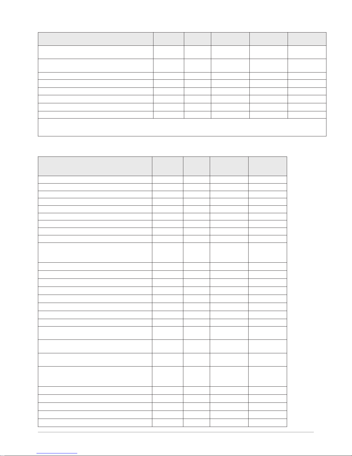
3.2.4 Combination heaters with medium-temperature heat
pump
Tab.11 Technical parameters for heat pump combination heaters (parameters declared for medium-temperature application)
Product name iMPI V200
AWHP 4.5 MR
iMPI V200
AWHP 6 MR-3
iMPI V200
AWHP 8 MR-2
Air-to-water heat pump Yes Yes Yes
Water-to-water heat pump No No No
3 Technical specifications
14 iMPI V200 7700954 - v03 - 13082018
Page 15

Product name iMPI V200
AWHP 4.5 MR
iMPI V200
AWHP 6 MR-3
iMPI V200
AWHP 8 MR-2
Brine-to-water heat pump No No No
Low-temperature heat pump No No No
Equipped with a supplementary heater Yes Yes Yes
Heat pump combination heater Yes Yes Yes
Rated heat output under average conditions
(1)
Prated
kW 4 4 6
Rated heat output under colder conditions
Prated
kW 5 4 6
Rated heat output under warmer conditions
Prated
kW 4 5 6
Declared capacity for heating for part load at an in
door temperature of 20 °C and outdoor temperature
T
j
T
j
= -7 °C
Pdh
kW 3.8 3.5 5.6
T
j
= +2 °C
Pdh
kW 4.3 4.5 2.9
T
j
= +7 °C
Pdh
kW 4.5 4.8 6.4
T
j
= +12 °C
Pdh
kW 5.5 5.2 4.3
T
j
= bivalent temperature
Pdh
kW 3.9 3.6 5.2
T
j
= operation limit temperature
Pdh
kW 3.9 3.6 5.2
Bivalent temperature
T
biv
°C -10 -10 -10
Degradation coefficient
(2)
Cdh
— 1.0 1.0 1.0
Seasonal space heating energy efficiency under
average conditions
ƞ
s
% 134 137 129
Seasonal space heating energy efficiency under
colder conditions
ƞ
s
% 109 116 119
Seasonal space heating energy efficiency under
warmer conditions
ƞ
s
% 179 172 169
Declared coefficient of performance or primary en
ergy ratio for part load at an indoor temperature of
20 °C and outdoor temperature
T
j
T
j
= -7 °C
COPd
- 1.64 1.89 1.95
T
j
= +2 °C
COPd
- 3.46 3.53 3.22
T
j
= +7 °C
COPd
- 4.96 4.74 4.57
T
j
= +12 °C
COPd
- 7.90 7.08 6.55
T
j
= bivalent temperature
COPd
- 1.20 1.52 1.70
T
j
= operation limit temperature
COPd
- 1.20 1.52 1.70
Operation limit temperature for air-to-water heat
pumps
TOL
°C -10 -10 -10
Heating water operating limit temperature
WTOL
°C 55 60 60
Electrical power consumption
Off mode
P
OFF
kW 0.009 0.009 0.009
Thermostat-off mode
P
TO
kW 0.049 0.049 0.049
Stand-by
P
SB
kW 0.009 0.015 0.014
Crankcase heater mode
P
CK
kW 0.000 0.055 0.055
Supplementary heater
Rated heat output
Psup
kW 0.0 0.0 0.0
Type of energy input Electricity Electricity Electricity
Other specifications
Capacity control Variable Variable Variable
Sound power level, indoors - outdoors
L
WA
dB 49 – 61 49–65 49 – 67
Annual energy consumption under average con
ditions
Q
HE
kWh 2353 2124 3499
Annual energy consumption under colder condi
tions
Q
HE
kWh 4483 3721 4621
3 Technical specifications
7700954 - v03 - 13082018 iMPI V200 15
Page 16
Product name iMPI V200
AWHP 4.5 MR
iMPI V200
AWHP 6 MR-3
iMPI V200
AWHP 8 MR-2
Annual energy consumption under warmer condi
tions
Q
HE
kWh 1249 1492 1904
Rated air flow rate, outdoors for air-to-water heat
pumps
—
m3/h
2100 2100 3300
Declared load profile L L L
Daily electricity consumption
Q
elec
kWh 4.020 4.816 4.816
Annual electricity consumption
AEC
kWh 845 968 968
Water heating energy efficiency
ƞ
wh
% 121.00 106.00 106.00
Daily fuel consumption
Q
fuel
kWh 0.000 0.000 0.000
Annual fuel consumption
AFC
GJ 0 0 0
(1) The rated heat output
Prated
is equal to the design load for heating
Pdesignh
, and the rated heat output of a supplementary heater
Psup
is
equal to the supplementary capacity for heating
sup(Tj)
.
(2) If
Cdh
is not determined by measurement, the default degradation coefficient is
Cdh
= 0.9.
Tab.12 Technical parameters for heat pump combination heaters (parameters declared for medium-temperature application)
Product name iMPI V200
AWHP 11 MR-2
AWHP 11 TR-2
iMPI V200
AWHP 16 MR-2
AWHP 16 TR-2
Air-to-water heat pump Yes Yes
Water-to-water heat pump No No
Brine-to-water heat pump No No
Low-temperature heat pump No No
Equipped with a supplementary heater Yes Yes
Heat pump combination heater Yes Yes
Rated heat output under average conditions
(1)
Prated
kW 6 9
Rated heat output under colder conditions
Prated
kW 4 7
Rated heat output under warmer conditions
Prated
kW 8 13
Declared capacity for heating for part load at an in
door temperature of 20 °C and outdoor tempera
ture
T
j
T
j
= -7 °C
Pdh
kW 5.9 9.0
T
j
= +2°C
Pdh
kW 5.3 6.5
T
j
= +7 °C
Pdh
kW 9.0 12.9
T
j
= +12 °C
Pdh
kW 7.7 10.0
T
j
= bivalent temperature
Pdh
kW 6.3 8.8
T
j
= operation limit temperature
Pdh
kW 6.3 8.8
Bivalent temperature
T
biv
°C -10 -10
Degradation coefficient
(2)
Cdh
— 1.0 1.0
Seasonal space heating energy efficiency under
average conditions
ƞ
s
% 125 121
Seasonal space heating energy efficiency under
colder conditions
ƞ
s
% 113 113
Seasonal space heating energy efficiency under
warmer conditions
ƞ
s
% 167 161
Declared coefficient of performance or primary en
ergy ratio for part load at an indoor temperature of
20 °C and outdoor temperature
T
j
T
j
= -7 °C
COPd
- 1.87 1.85
T
j
= +2 °C
COPd
- 3.17 3.02
T
j
= +7 °C
COPd
- 4.54 4.34
T
j
= +12 °C
COPd
- 6.19 5.75
T
j
= bivalent temperature
COPd
- 1.20 1.35
3 Technical specifications
16 iMPI V200 7700954 - v03 - 13082018
Page 17

Product name iMPI V200
AWHP 11 MR-2
AWHP 11 TR-2
iMPI V200
AWHP 16 MR-2
AWHP 16 TR-2
T
j
= operation limit temperature
COPd
- 1.20 1.35
Operation limit temperature for air-to-water heat
pumps
TOL
°C -10 -10
Heating water operating limit temperature
WTOL
°C 60 60
Electrical power consumption
Off mode
P
OFF
kW 0.009 0.009
Thermostat-off mode
P
TO
kW 0.023 0.035
Stand-by
P
SB
kW 0.023 0.023
Crankcase heater mode
P
CK
kW 0.055 0.055
Supplementary heater
Rated heat output
Psup
kW 0.0 0.0
Type of energy input Electricity Electricity
Other specifications
Capacity control Variable Variable
Sound power level, indoors - outdoors
L
WA
dB 48–69 48 – 70
Annual energy consumption under average con
ditions
Q
HE
kWh 3999 5861
Annual energy consumption under colder condi
tions
Q
HE
kWh 3804 5684
Annual energy consumption under warmer condi
tions
Q
HE
kWh 2580 4120
Rated air flow rate, outdoors for air-to-water heat
pumps
—
m3/h
6000 6000
Declared load profile L L
Daily electricity consumption
Q
elec
kWh 4.816 4.816
Annual electricity consumption
AEC
kWh 968 968
Water heating energy efficiency
ƞ
wh
% 106.00 106.00
Daily fuel consumption
Q
fuel
kWh 0.000 0.000
Annual fuel consumption
AFC
GJ 0 0
(1) The rated heat output
Prated
is equal to the design load for heating
Pdesignh
, and the rated heat output of a supplemen
tary heater
Psup
is equal to the supplementary capacity for heating
sup(Tj)
.
(2) If
Cdh
is not determined by measurement, the default degradation coefficient is
Cdh
= 0.9.
See
The back cover for contact details.
3.2.5 Circulating pump
Important
The benchmark for the most efficient circulating pumps is EEI ≤
0.20.
3 Technical specifications
7700954 - v03 - 13082018 iMPI V200 17
Page 18
4 Description of the product
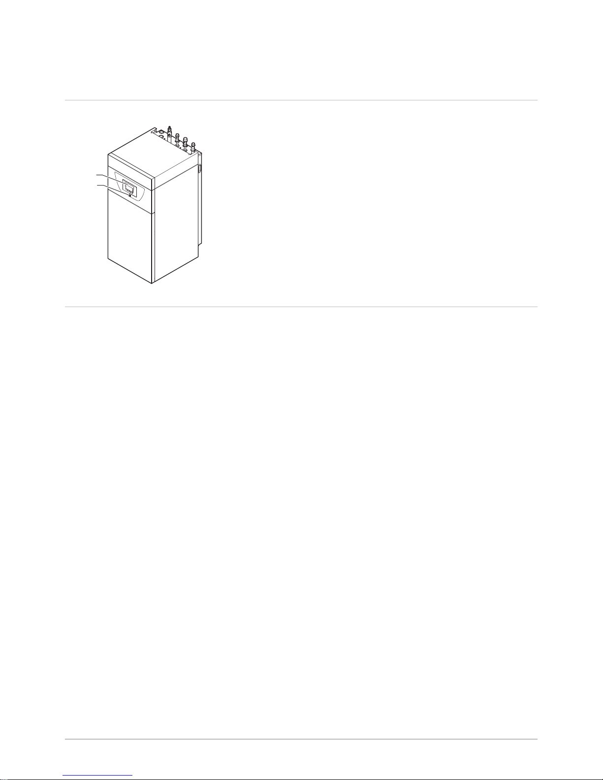
4.1 Main components
1
Control panel
2
ON/OFF button
4.2 Operating principle
The heat pumps in the iMPI V200 range extract the heat found in the air to
restore it to the heating and/or domestic hot water circuit via the refrigerant
fluid. The efficiency of a heat pump is expressed in the form of a
coefficient of performance (COP), defined as the ratio between the heat
provided and the power consumed.
The heat pump comprises an evaporator, a compressor, a condenser and
an expansion valve. The indoor module includes the condenser. The other
components (evaporator, compressor and expansion valve) are located in
the outdoor unit.
1. The refrigerant fluid in the circuit is converted from the liquid state to
the gaseous state in the evaporator, making it possible to recover heat
from the air.
2. The compressor increases the fluid pressure, which thus increases
the temperature.
3. In the condenser, the fluid transfers the heat to the heating circuit
while converting to the liquid state.
4. The refrigerant passes through the thermostatic expansion valve and
returns to the initial state at low pressure and low temperature before
returning to the evaporator.
Fig.3
Main components
MW-3000525
1
2
4 Description of the product
18 iMPI V200 7700954 - v03 - 13082018
Page 19

Fig.4 General operating principle
5
2
1
3
6
4
7
8
MW-6000391-1
1 Evaporator (fin battery in the outdoor unit)
2 Compressor
3 Condenser (plate exchanger in the indoor module)
4 Electronic expansion valve
5 Electrical energy
6 Heating water
7 Energy flow
8 Heat recovered from the environment
4.3 Control panel description
4.3.1 Description of the keys
1
h
: back to the previous level without saving the modifications
made
: manual reset
2
: accessing the heating parameters
: lowering the value
3
: accessing the domestic hot water parameters
: raising the value
4
: MODE display
: accessing the menu selected or confirming the value
modification
4.3.2 Description of the display
Hydraulic back-up
Hydraulic back-up in demand
Fig.5
MW-1000043-5
1 2 3 4
Fig.6
MW-1000669-2
4 Description of the product
7700954 - v03 - 13082018 iMPI V200 19
Page 20

Electrical back-up
Stage 1 of the electrical back-up
Stage 2 of the electrical back-up
Status of the Compressor
Steady symbol: compressing running
Operating modes
Steady symbol: heating function enabled
Flashing symbol: heating production running
Steady symbol: domestic hot water function enabled
Flashing symbol: domestic hot water production running
Heating or cooling function disabled
Domestic hot water function disabled
Hydraulic pressure in the system
The display alternates between the hydraulic pressure for the system and
the measured flow temperature.
Steady symbol: displayed when indicating the system's hydraulic
pressure value
Flashing symbol: pressure in the system too low
XXX Pressure value in the system (in bar) or flow temperature (in °C)
Cooling mode
Steady symbol: cooling mode on
Flashing symbol: cooling request pending
Menu display
Information menu: displays the measured values and the statuses
of the appliance
User menu: provides access to the User level setting parameters
Installer menu: provides access to the Installer level setting
parameters
Manual Forcing menu: the appliance runs at the set point
displayed, the pumps operate and the three-way valves are not
controlled.
Malfunction menu: the appliance has malfunctioned. This
information is signalled by an error code and a flashing display.
Sub-Menu COUNTERS
TIME PROG sub-menu: Timer programming dedicated to
heating and domestic hot water production
Fig.7
MW-1000665-2
Fig.8
MW-5000012-3
Fig.9
MW-1000083-5
Fig.10
MW-5000037-4
Fig.11
MW-5000015-3
Fig.12
4 Description of the product
20 iMPI V200 7700954 - v03 - 13082018
Page 21

Sub-Menu CLOCK
PCB selection menu: access to information on the additional PCBs
connected
Display of PCB names
The name of the PCB for which the parameters are displayed is
scrolling across the screen on 3 characters.
Central unit PCB EHC-04: direct circuit and domestic hot water
Additional PCB SCB-04 : 2nd circuit
COUNTERS / TIME PROG / Sub-Menus CLOCK
COUNTERS sub-menu (CNT)
TIME PROG sub-menu: Timer programming dedicated to
heating and domestic hot water production (CIRC A, CIRC B,
ECS)
Timer program for Monday
Timer program for Tuesday
Timer program for Wednesday
Timer program for Thursday
Timer program for Friday
Timer program for Saturday
Timer program for Sunday
CLOCK sub-menu (CLK)
Temperature sensors
Room temperature sensor connected:
fixed symbol for WINTER mode,
flashing symbol for SUMMER mode.
Outside temperature sensor connected:
fixed symbol for WINTER mode,
flashing symbol for SUMMER mode.
Other Information
Test Menu: forced operation in heating and cooling mode
Three-way valve connected
Three-way valve closed
Three-way valve open
Pump running
Fig.13
MW-1000670-1
Fig.14
MW-1000754-2
...EHC / --04...
Fig.15
MW-1000687-1
...SCB / 04- / B...
Fig.16
MW-1000575-2
Fig.17
MW-5000014-4
Fig.18
MW-5000038-4
4 Description of the product
7700954 - v03 - 13082018 iMPI V200 21
Page 22

5 Operation
5.1 Using the user interface
5.1.1 Browsing in the menus
Press any key to turn on the backlight for the control panel screen.
If no key is pressed within 3 minutes, the control panel backlight will go
out.
Press the 2 right-hand keys together to access the different menus:
Tab.13 Menus available
Information menu
User menu
Installer menu
Manual Forcing menu
Malfunction menu
COUNTERS sub-menu
TIME PROG sub-menu
CLOCK sub-menu
PCB selection menu
Important
The icon is displayed only if an optional PCB has
been installed.
Important
The different menus are only accessible when the icons flash.
Press the key to:
access the next menu,
access the next sub-menu,
access the next parameter,
increase the value.
Press the key to:
access the previous menu,
access the previous sub-menu,
access the previous parameter
decrease the value.
Press the confirmation key to confirm:
a menu,
a sub-menu,
a parameter,
a value.
When the temperature is displayed, briefly pressing the back key h will
return to the time display.
5.2
Start-up
1. Switch on the outdoor unit and the indoor module.
2. The heat pump begins its start-up cycle.
If the start-up cycle runs normally, an automatic venting cycle is
initiated. Otherwise, an error message is displayed.
Fig.19
MW-2000369-1
Fig.20
MW-1000576-2
Fig.21
MW-2000370-2
Fig.22
MW-2000371-1
5 Operation
22 iMPI V200 7700954 - v03 - 13082018
Page 23

5.3 Shutdown
5.3.1 Switching off the heating
Important
Heating mode can be managed via the TIME PROG sub-menu
dedicated to timer programming.
Important
If the heating function is shut off, then the cooling will also be shut
off.
1. Go to stop mode by pressing the key.
2. Select the heating mode by pressing the key.
3. Confirm by pressing the key.
4. Select the heating shut-down pressing the key.
The screen displays: .
The frost protection function continues to run.
The heating and cooling have been shut down.
Important
Press the key to restart the appliance: the screen will
display .
5. Confirm by pressing the key.
6. Go back to the main display by pressing the h key.
Important
The display disappears after a few seconds of inactivity.
Fig.23
MW-5000027-4
Fig.24
MW-5000133-3
Fig.25
MW-5000134-3
5 Operation
7700954 - v03 - 13082018 iMPI V200 23
Page 24

5.3.2 Stopping domestic hot water production
Important
Domestic hot water production can be managed via the TIME
PROG sub-menu dedicated to timer programming.
1. Go to stop mode by pressing the key.
2. Select domestic hot water production mode pressing the key.
3. Confirm by pressing the key.
4. Select domestic hot water production shut-down by pressing the
key.
The screen displays: .
The frost protection function continues to run.
Production of domestic hot water has been shut down.
Important
Press the key to restart the appliance: the screen will
display .
5. Confirm by pressing the key.
6. Go back to the main display by pressing the h key.
Important
The display disappears after a few seconds of inactivity.
5.3.3 Shutting down the cooling function
Important
If the heating function is shut off, then the cooling will also be shut
off.
1. Access the menu.
2. Confirm access by pressing the key.
3. Select CIRCA or CIRCB by pressing the or key.
4. Confirm the selection by pressing the key.
5. Select TP.C by pressing the or keys.
6. Confirm the selection by pressing the key.
7. Modify the timer program to stop cooling.
For more information, see
Switching off the heating, page 23
Fig.26
MW-5000135-3
Fig.27
MW-5000136-3
Fig.28
MW-5000028-4
5 Operation
24 iMPI V200 7700954 - v03 - 13082018
Page 25

5.4 Frost Protection
If the temperature of the heating water in the heat pump falls too much,
the integrated protection device switches itself on. This device functions as
follows:
If the water temperature is lower than 5°C, the circulating pump starts
up.
If the water temperature is lower than 3°C, the back-up starts up.
If the water temperature is higher than 10°C, the back-up shuts down
and the circulating pump continues to run for a short time.
The radiator valves in rooms where there is a risk of frost must be fully
open.
5 Operation
7700954 - v03 - 13082018 iMPI V200 25
Page 26

6 Settings
6.1 Modifying the User parameters
Caution
Altering the factory settings may impair operation of the appliance.
1. Go to the User menu.
2. Select the desired sub-menu by pressing the or key.
3. Confirm the selection by pressing the key.
4. Select the required parameter by pressing the or keys to scroll
through the list of adjustable parameters.
5. Confirm the selection by pressing the key.
6. Modify the value of the parameter using the or keys.
7. Confirm the new value of the parameter by pressing the key.
8. Go back to the main display by pressing the h key.
6.2 User menu
Fig.31
1
2
MW-2000435-1
3
2
1 Sub-menu available
2 Name of the PCB or circuit
3 Setting parameters
Tab.14
List of User sub-menus
Sub-menu Description Name of the PCB or circuit
CIRCA Main heating circuit
CIRCB Additional heating circuit B
ECS Domestic hot water circuit
EHC-04 Central unit PCB EHC-04
SCB-04 Additional PCB for circuit B
HMI HMI control panel
6.2.1 User \CIRCA and CIRCB menu
CP : Circuits Parameters = Heating circuit parameters
Tab.15
Parameter Description Factory setting
CIRCA
Factory setting
CIRCB
CP010 Zone flow temperature setpoint, used when the zone is set to a fixed
flow setpoint.
not available 50
CP080 User Room Setpoint Zone Activity temperature
Can be set from 5 °C to 30 °C
16 16
CP081 User Room Setpoint Zone Activity temperature in activity zone 2
Can be set from 5 °C to 30 °C
20 20
Fig.29
MW-5000008-2
Fig.30
MW-5000040-6
6 Settings
26 iMPI V200 7700954 - v03 - 13082018
Page 27

Parameter Description Factory setting
CIRCA
Factory setting
CIRCB
CP082 User Room Setpoint Zone Activity temperature in activity zone 3
Can be set from 5 °C to 30 °C
6 6
CP083 User Room Setpoint Zone Activity temperature in activity zone 4
Can be set from 5 °C to 30 °C
21 21
CP084 User Room Setpoint Zone Activity temperature in activity zone 5
Can be set from 5 °C to 30 °C
22 22
CP085 User Room Setpoint Zone Activity temperature in activity zone 6
Can be set from 5 °C to 30 °C
23 20
CP140 Setpoint of the Room Cooling Temperature of the zone: cooling ac
tivity zone 1
Can be set from 20 °C to 30 °C
30 30
CP141 Setpoint of the Room Cooling Temperature of the zone: cooling ac
tivity zone 2
Can be set from 20 °C to 30 °C
25 25
CP142 Setpoint of the Room Cooling Temperature of the zone: cooling ac
tivity zone 3
Can be set from 20 °C to 30 °C
25 25
CP143 Setpoint of the Room Cooling Temperature of the zone: cooling ac
tivity zone 4
Can be set from 20 °C to 30 °C
25 25
CP144 Setpoint of the Room Cooling Temperature of the zone: cooling ac
tivity zone 5
Can be set from 20 °C to 30 °C
25 25
CP145 Setpoint of the Room Cooling Temperature of the zone: cooling ac
tivity zone 6
Can be set from 20 °C to 30 °C
25 25
CP200 Manually setting the RoomTemperature setpoint of the zone
Can be set from 5 °C to 30 °C
20 20
CP320 Operating mode of the zone
0 = timer programming
1 = manual mode
2 = frost protection mode
0 0
CP350 Comfort Domestic Hot Water Temperature Setpoint of zone
Can be set from 40 °C to 80 °C
not available 55
CP360 Reduced Domestic Hot Water Temperature Setpoint of zone
Can be set from 10 °C to 60 °C
not available 10
CP510 Temporary room setpoint per zone
Can be set from 5 °C to 30 °C
20 20
CP540 Setpoint of swimming pool when Zone is configured on
SwimmingPool
Can be set from 0 °C to 39 °C
not available 20
CP550 Fire Place mode is active
0 = off
1 = on
0 0
6 Settings
7700954 - v03 - 13082018 iMPI V200 27
Page 28

Parameter Description Factory setting
CIRCA
Factory setting
CIRCB
CP570 Time Program of the zone selected by the user
0 = programme 1
1 = programme 2
2 = programme 3
0 0
CP660 Choice icon to display this zone
0 =None
1 =All
2 =Bedroom
3 =Livingroom
4 =Study
5 =Outdoor
6 =Kitchen
7 =Basement
8 =Swimming pool
0 3
6.2.2 User \DHW menu
DP : Direct Hot Water Parameters = Domestic hot water tank parameters
Tab.16
Parameter Description Factory setting
DP060 Time program selected for DHW.
0 =Schedule 1
1 =Schedule 2
2 =Schedule 3
3 =Cooling
0
DP070 Comfort temperature setpoint from the Domestic Hot Water tank
Can be set from 40 °C to 65 °C
54
DP080 Reduced temperature setpoint from the Domestic Hot Water tank
Can be set from 10 °C to 60 °C
10
DP200 DHW primary mode current working setting
0 =Scheduling
1 =Manual
2 =Antifrost
3 =Temporary
1
DP337 Holiday temperature setpoint from the Domestic Hot Water tank
Can be set from 10 °C to 60 °C
10 °C
6.2.3 User \EHC–04 menu
AP : Appliance Parameters = Appliance parameters
Tab.17
Parameter Description Factory setting
AP015 Force manually the heat pump in cooling mode
0 =No
1 =Yes
0
AP016 Enable central heating heat demand processing
0= off (no heating or cooling)
1 = on
1
AP017 Enable domestic hot water heat demand processing
0 = off
1 = on
1
6 Settings
28 iMPI V200 7700954 - v03 - 13082018
Page 29

Parameter Description Factory setting
AP073 Outdoor temperature: upper limit for heating
SUMMER / WINTER set point switch:
Can be set from 15 °C to 30.5 °C
22
AP074 The heating is stopped. Hot water is maintained. Force Summer Mode
SUMMER override:
0 = off
1 = on
0
AP082 Automatic change between summer and winter time
0 = Off
1 = On
0
HP : Heat-pump Parameters = Heat pump parameters
Tab.18
Parameter Description Factory setting
HP062 Energy cost in Hybrid electricity cost in high tarif
Can be set from 0.01 to 2.50 €/kWh
0.13 €/kWh
HP063 Energy cost in Hybrid electricity cost in low tarif
Can be set from 0.01 to 2.50 €/kWh
0.09 €/kWh
HP064 Cost of fossil energy (oil or gas) - price per litre or per m3
Cost of fossil energy (oil or gas) - price per litre or per m
3
Can be set from 0.01 to 2.50 €/kWh
0.90 €/kWh
6.2.4 User \HMI menu
Tab.19 AP : Appliance Parameters = Appliance parameters
Parameter Description Factory setting
AP067 BKL backlighting
0 = off after 3 minutes of inactivity on the control panel
1 = on
0
AP103 Setting the LANGUAGE:
0 = no language
FR = French
NL = Dutch
EN = English
DE = German
ES = Spanish
IT = Italian
PL = Polish
PT = Portuguese
FR
AP104 Setting the CONTRAST:
Can be set from 0 to 3
3
AP105 Selecting the UNIT:
0 = °C
1 = °F
0
AP082 Changing the DLS summer/winter timer:
0 = off
1 = on
0
6.2.5 HP parameters in the User menu
HP : Heat-pump Parameters = Heat pump parameters
6 Settings
7700954 - v03 - 13082018 iMPI V200 29
Page 30

Tab.20
Parameter Description Factory setting
HP062 Energy cost in Hybrid electricity cost in high tarif
Can be set from 0.01 to 2.50 €/kWh
0.13 €/kWh
HP063 Energy cost in Hybrid electricity cost in low tarif
Can be set from 0.01 to 2.50 €/kWh
0.09 €/kWh
HP064 Cost of fossil energy (oil or gas) - price per litre or per m3
Cost of fossil energy (oil or gas) - price per litre or per m
3
Can be set from 0.01 to 2.50 €/kWh
0.90 €/kWh
6.3
COUNTERS /TIME PROG / CLOCK menus
Tab.21
List of sub-menus
Sub-menu Description
CNT COUNTERS
CIRCA Timer programming for the main heating circuit
CIRCB Timer programming for the additional heating circuit B
DHW Timer programming for the domestic hot water circuit
CLK Setting the clock and the date
6.3.1 COUNTERS, TIME PROG, CLOCK \CNT menus
Tab.22 Choosing the menu
Counters Selection
Circuit A counters Choose the EHC-04 menu
Circuit B counters Choose the SCB04-B menu
Counters connected to the opera
tion of the heat pump
Choose the EHC-04 menu
Tab.23 Available counters
Parameter Description Unit EHC-04 SCB04-B
AC001 Number of hours that the appliance has been on
mains power
hours X X
AC005 Energy consumed for central heating kWh X
AC006 Enegy consumed for domestic hot water Wh X
AC007 Energy consumed for cooling Wh X
AC008 Energy delivered for central heating kWh X
AC009 Energy delivered for domestic hot water kWh X
AC010 Energy delivered for cooling kWh X
AC013 Seasonal COP X
AC026 Counter that shows the number of pump running
hours
hours X
AC027 Counter that shows the number of pump starts - X
AC028 Total working time of the first stage of backup hours X
AC029 Total working time of the second stage of backup hours X
AC030 Total startings of the first stage of backup - X
AC031 Total startings of the second stage of backup - X
DC002 Numbers of Domestic Hot Water diverting valve
cycles
- X
6 Settings
30 iMPI V200 7700954 - v03 - 13082018
Page 31

Parameter Description Unit EHC-04 SCB04-B
DC003 Number of hours during which the diverting valve
is in DHW position
hours X
DC004 Number of compressor start-ups during domestic
hot water production
X
DC005 Number of compressor start-ups X
PC002 Number of compressor start-ups - - X
PC003 Number of compressor operating hours hours X
CODE Enter the installer code to access the following pa
rameters.
X
AC002 Number of hours that the appliance has been
producing energy since last service
hours X
AC003 Number of hours since the previous servicing of
the appliance
hours X
AC004 Number of heat generator starts since the
previous servicing.
X
AC013 Seasonal coefficient of performance X
SERVICE Resetting the maintenance service
CLR: the AC002, AC003, and AC004 counters are
reset to zero.
X
6.3.2 COUNTERS, TIME PROG, CLOCK \CIRCA, CIRCB
and DHW menus
Tab.24
Menu Description
CIRCA TP.H: Timer programming for heating
06:00 - 23:00 ON
23:00 - 06:00 OFF
TP.C: Timer programming for cooling
14:00 - 23:00 ON
23:00 - 14:00 OFF
CIRCB Timer programming for heating
06:00 - 23:00 ON
23:00 - 06:00 OFF
DHW Timer programming for domestic hot water
06:00 - 23:00 ON
23:00 - 06:00 OFF
6.3.3 COUNTERS, TIME PROG, CLOCK \CLK menus
Tab.25
CLK parameter Unit HMI
HOURS Can be set from 0 to 23 available
MINUTE Can be set from 0 to 59 available
DATE Can be set from 1 to 31 available
MONTH Can be set from 1 to 12 available
YEAR Can be set from 2000 to 2100 available
6 Settings
7700954 - v03 - 13082018 iMPI V200 31
Page 32

6.4 Setting the parameters
6.4.1 Setting the room temperature set point in comfort mode
Important
The room temperature set point can be managed via the TIME
PROG sub-menu dedicated to timer programming.
Important
To set the room set point temperature in reduced mode, it is
necessary to set the CP080 parameter available in the User
menu.
When the setting is made in a reduced mode range, this setting
shortcut is used only to set the set point temperature in comfort
mode corresponding to the CP081.
1. Access the heating parameters by pressing the key twice.
2. Display the parameters for the required circuit by pressing the or
key.
3. Confirm by pressing the key.
The name of the circuit and the heating water temperature set point
are displayed alternately.
4. Access setting of the heating water temperature set point by pressing
the key.
5. Set the heating water temperature set point by pressing the or
key.
6. Confirm the new temperature set point by pressing the key.
Important
Press the h key to cancel all inputs.
6.4.2 Setting the domestic hot water temperature
Important
Domestic hot water production can be managed via the TIME
PROG sub-menu dedicated to timer programming.
1. Access the domestic hot water production parameters by pressing the
key.
2. Modify the domestic hot water temperature set point by pressing the
or key.
Important
Press the h key to cancel all input.
3. Confirm the new temperature set point by pressing the key.
Go back to the main display by pressing the h key.
6.4.3 Activating Forcing of the cooling function
The cooling function can be managed via the PROG COOL sub-menu
dedicated to timer programming.
The set point flow temperature for cooling mode corresponds to the
CP270 parameter for underfloor heating and CP280 for a convection fan.
The CP270 and CP280 parameters can be accessed by the Installer.
Fig.32
MW-5000144-3
Fig.33
MW-3000249-4
Fig.34
MW-6000254-2
6 Settings
32 iMPI V200 7700954 - v03 - 13082018
Page 33

Important
The heat pump switches to cooling automatically when the
outdoor temperature is +2 °C greater than the summer/winter
switching set point temperature (22 °C). The forced cooling
function is used to have cooling regardless of the outdoor
temperature.
1. Access Forcing of the cooling function by pressing the key.
Important
Forcing of the cooling function is possible only if the Installer
enabled the cooling function during Installation.
2. Access Forcing of the cooling function by pressing the key.
3. Activate Forcing of the cooling function by pressing the key.
4. Confirm Forcing of the cooling function by pressing the key.
5. Go back to the main display by pressing the h key.
6.4.4
Activating Manual Forcing for heating
The Manual Forcing menu is only used with the heating mode.
1. Access the Manual Forcing menu.
Fig.35
MW-5000401-2
Fig.36
MW-5000402-2
Fig.37
MW-5000403-2
Fig.38
MW-5000404-2
Fig.39
MW-5000010-4
6 Settings
7700954 - v03 - 13082018 iMPI V200 33
Page 34

2. Set the value of the heating water temperature set point by pressing
the or key.
3. Confirm the new value of the heating water temperature set point by
pressing the
key.
4. Go back to the main display by pressing the h key.
Important
To force domestic hot water production, select the DP200
parameter available in the User menu.
6.4.5 Setting the timer programming
1. Access the COUNTERS/ TIME PROG / CLOCK menus.
Important
When using a programmable room thermostat, this menu is not
displayed.
2. Select the desired circuit by pressing the or key.
3. Confirm the selection by pressing the key. Select the timer
programming for the heating or the timer programming for the
cooling by pressing the or key.
4. Confirm the selection by pressing the key.
The icons dedicated to the days of the week all flash at the same
time: .
5. Select the desired day number by pressing the or key until the
icon dedicated to the desired day flashes.
Day selected Description
, , , , , , every day of the week
Monday
Tuesday
Wednesday
Thursday
Friday
Saturday
Sunday
Important
The key is used to move to the right.
The key is used to move to the left.
6. Confirm the selection by pressing the key.
Fig.40
MW-5000042-4
Fig.41
MW-5000044-4
Fig.42
MW-5000139-4
Fig.43
MW-5000486-1
Fig.44
MW-1000594-3
6 Settings
34 iMPI V200 7700954 - v03 - 13082018
Page 35

7. Set the start time for the period by pressing the or key.
8.
Confirm the selection by pressing the key.
9. Select the status that corresponds to the period by pressing
the or key.
Status
to for periods
to
Description
comfort mode
reduced mode
10. Confirm the selection by pressing the key.
11. Repeat steps 8 to 11 to define the comfort periods to and
the associated status to .
Important
No setting: 10 minutes
The setting determines the end.
12. Go back to the main display by pressing the h key.
Example:
Times
06:00-22:00 06:00 22:00
06:00-08:00
11:30-13:30
06:00 08:00 11:30 13:30
06:00-08:00
11:30-14:00
17:30-22:00
06:00 08:00 11:30 14:00 17:30 22:00
Fig.45
MW-5000142-2
Fig.46
MW-5000143-3
6 Settings
7700954 - v03 - 13082018 iMPI V200 35
Page 36

7 Reading out measured values
The measured values are available in the Information menu of the
different PCBs.
Certain parameters are displayed:
according to certain system configurations,
according to the options, circuits or sensors actually connected.
Tab.26 Choosing the menu
Counters Selection
Measured values on circuit A Choose menu EHC-04
Measured values on circuit B Choose menu SCB04-B
Measured values connected to the
operation of the heat pump
Choose menu EHC-04
Tab.27 Values available (X) in the sub-menus EHC-04, SCB04-B
Parameter Description Unit EHC-04 SCB04-B
AM002 "Silent mode" status X
AM010 The current pump speed % X
AM012 Current main status of the appliance.
See
Control system sequence chapter
X X
AM014 Current sub status of the appliance.
See
Control system sequence chapter
X X
AM015 Is the pump running? X
AM016 Flow temperature of appliance. °C X
AM019 Water pressure of the primary circuit. bar X
AM027 Instantaneous outside temperature °C X X
AM040 Temperature used for hot water control algorithms. °C X
AM056 Wate flow rate in the system l/min X
AM091 Seasonal mode active (summer / winter)
0: Winter
1: Frost protection
2: Summer neutral band
3: Summer
X X
AM101 Internal system flow temperature setpoint X
CM030 Measure of the Room temperature of the zone °C X X
CM040 Measure Zone Flow Temperature or DHW
temperature
°C X
CM060 Current Pump speed of zone % X
CM120 Zone Current Mode:
0 =Scheduling
1 =Manual
2 =Antifrost
3 =Temporary
X X
CM130 Current activity of the zone:
0 =Anti frost
1 =Reduced
2 =Comfort
3 =Anti legionella
X X
CM190 Wished room temperature setpoint of the zone °C X X
CM210 Current Outside Temperature of the zone °C X X
7 Reading out measured values
36 iMPI V200 7700954 - v03 - 13082018
Page 37

Parameter Description Unit EHC-04 SCB04-B
DM001 Domestic Hot Water tank temperature (bottom sensor) °C X
DM006 Domestic Hot Water tank temperature (top sensor) X
DM009 Automatic/derogation status of Domestic Hot Water
mode:
0 =Scheduling
1 =Manual
2 =Antifrost
3 =Temporary
°C X
DM029 Domestic Hot Water temperature setpoint °C X
HM001 Heat pump flow temperature after condenser °C X
HM002 Heat pump return temperature after condenser. °C X
HM033 Flow temperature setpoint in cooling mode °C X
HM034 Heat pump PCU backup flow temperature °C not used
HM035 Heat pump PCU backup return temperature °C not used
HM036 Heat pump PCU backup domestical hot water
temperature
°C not used
HM037 Heat pump PCU back up Internal Setpoint °C not used
HM038 Heat pump PCU back up status not used
HM039 Heat Pump PCU back up Sub Status not used
HM040 Heat Pump PCU back up Output power % not used
HM041 Heat pump PCU back up locking code not used
HM042 Heat pump PCU back up blocking code not used
HM046 Heat pump 5V signal output setpoint V X
PM002 Central heating setpoint of the appliance °C X
Fxx.xx Software version for the selected PCB X X
Pxx.xx Parameter version for the selected PCB X X
Tab.28
Values available (X) in the sub-menu
Parameter Description EHC--04 SCB04-B
F02.01 HMI software version X X
P00.01 HMI parameter version X X
7.1 Control system sequence
Tab.29 List of statuses and sub-statuses
Status Appliance: AM012 parameter Appliance sub status: AM014 parameter
0 00= total system shut-down
1= heating / cooling / domestic hot water de
mand
Heat Demand
00 = off
The set point is reached. The compressor can start up whenever necessary.
01= anti-short cycle
The heating set point has been reached. The compressor is not authorised to
restart.
02= reversal valve switch to heating position
03= power supply to the hybrid pump
04= pending start-up conditions on the heat pump and the back-ups
62= three-way valve switch to domestic hot water position
7 Reading out measured values
7700954 - v03 - 13082018 iMPI V200 37
Page 38

Status Appliance: AM012 parameter Appliance sub status: AM014 parameter
3= operating in heating mode 30= normal operation
The compressor or the back-ups are running.
31= internal set point limited
If the heating set point on the heat pump differs from the system set point.
60= pump post-operation
Heat pump and back-up shut-down, system pump operation.
65= compressor bypass
The back-ups are operating.
66= the temperature exceeds the compressor's maximum operating tempera
ture
The compressor has stopped. The back-ups are operating.
67= the outside temperature is lower than the compressor's maximum operat
ing temperature
The compressor has stopped. The back-ups are operating.
68= the hybrid function requests compressor shut-down
The compressor has stopped. The back-ups are operating.
69= defrosting running
The compressor is running.
70= defrosting conditions not met
The compressor has stopped. The back-ups are operating.
71= defrosting running
The compressor and the back-ups are running.
88 = BL-Back-up limited
Back-ups shed
89 = BL-Heat pump limited
Compressor shed
90 = BL-Heat pump & back-up limited
Compressor and back-ups shed
91 = BL-Off-peak rate
Off-peak cost
92 = PV-with Heat pump
Photovoltaic powered by compressor only
93 = PV-with Heat pump & back-up
Photovoltaic powered by compressor and back-ups
94 = BL-Smart Grid
Smart Grid Ready function
7 Reading out measured values
38 iMPI V200 7700954 - v03 - 13082018
Page 39

Status Appliance: AM012 parameter Appliance sub status: AM014 parameter
4= operating in domestic hot water mode 30= normal operation
The compressor or the back-ups are running.
31= internal set point limited
If the heating set point on the heat pump differs from the system set point.
60= pump post-operation
Heat pump and back-up shut-down, system pump operation.
65= compressor bypass
The back-ups are operating.
66= the temperature exceeds the compressor's maximum operating tempera
ture
The compressor has stopped. The back-ups are operating.
67= the outside temperature is lower than the compressor's maximum operat
ing temperature
The compressor has stopped. The back-ups are operating.
68= the hybrid function requests compressor shut-down
The compressor has stopped. The back-ups are operating.
69= defrosting running
The compressor is running.
70= defrosting conditions not met
The compressor has stopped. The back-ups are operating.
71= defrosting running
The compressor and the back-ups are running.
88 = BL-Back-up limited
Back-ups shed
89 = BL-Heat pump limited
Compressor shed
90 = BL-Heat pump & back-up limited
Compressor and back-ups shed
91 = BL-Off-peak rate
Off-peak cost
92 = PV-with Heat pump
Photovoltaic powered by compressor only
93 = PV-with Heat pump & back-up
Photovoltaic powered by compressor and back-ups
94 = BL-Smart Grid
Smart Grid Ready function
6 Pump Post Run
60= pump post-operation
Heat pump and back-up shut-down, system pump post-operation.
7 Cooling Active
30= normal operation
Cooling is active.
75= compressor shut-down owing to the condensation detector
78= correction of the temperature set point
Increase in the cooling set point owing to the condensation detector.
82= temperature lower than the minimum cooling temperature
Compressor shut-down.
7 Reading out measured values
7700954 - v03 - 13082018 iMPI V200 39
Page 40

Status Appliance: AM012 parameter Appliance sub status: AM014 parameter
8= controlled compressor shut-down Controlled Stop
00= off: the heating or cooling set point has been reached
01= anti-short cycle
The heating set point has been reached. The compressor is not authorised to
restart.
60= pump post-operation
Heat pump and back-up shut-down, system pump post-operation.
67= the outside temperature is lower than the compressor's maximum operat
ing temperature
The compressor has stopped. The back-ups are operating.
68= the hybrid function requests compressor shut-down
The compressor has stopped. The back-ups are operating.
75= compressor shut-down owing to the condensation detector
76= compressor shut-down owing to the flow rate
79= compressor and back-up bypass in heating / domestic hot water mode
80= compressor and back-up bypass in cooling mode
82= temperature lower than the minimum cooling temperature
Compressor shut-down.
9 Blocking Mode
30= normal operation.
The compressor or the back-ups are running.
31= internal set point limited
If the heating set point on the heat pump differs from the system set point.
60= pump post-operation
Heat pump and back-up shut-down, system pump running.
65= compressor bypass
The back-ups are operating.
66= the temperature exceeds the compressor's maximum operating tempera
ture
The compressor has stopped. The back-ups are operating.
67= the outside temperature is lower than the compressor's maximum operat
ing temperature
The compressor has stopped. The back-ups are operating.
68= the hybrid function requests compressor shut-down
The compressor has stopped. The back-ups are operating.
69= defrosting running
The compressor is running.
70= defrosting conditions not met
The compressor has stopped. The back-ups are operating.
71= defrosting running.
The compressor and the back-ups are running.
88 = BL-Back-up limited
Back-ups shed
89 = BL-Heat pump limited
Compressor shed
90 = BL-Heat pump & back-up limited
Compressor and back-ups shed
91 = BL-Off-peak rate
Off-peak cost
92 = PV-with Heat pump
Photovoltaic powered by compressor only
93 = PV-with Heat pump & back-up
Photovoltaic powered by compressor and back-ups
94 = BL-Smart Grid
Smart Grid Ready function
10 Locking Mode
11 Load test min
7 Reading out measured values
40 iMPI V200 7700954 - v03 - 13082018
Page 41

Status Appliance: AM012 parameter Appliance sub status: AM014 parameter
12 Load test CH max
30= normal operation. The compressor or the back-ups are running.
31= internal set point limited
If the heating set point on the heat pump differs from the system set point.
60= pump post-operation
Heat pump and back-up shut-down, system pump post-operation.
65= compressor bypass and back-ups running
66= the temperature exceeds the compressor's maximum operating tempera
ture
The compressor has stopped. The back-ups are operating.
67= the outside temperature is lower than the compressor's maximum operat
ing temperature
The compressor has stopped. The back-ups are operating.
68= the hybrid function requests compressor shut-down
The compressor has stopped. The back-ups are operating.
69= defrosting running
The compressor is running.
70= defrosting conditions not provided
The compressor has stopped. The back-ups are operating.
71= defrosting running.
The compressor and the back-ups are running.
7 Reading out measured values
7700954 - v03 - 13082018 iMPI V200 41
Page 42

Status Appliance: AM012 parameter Appliance sub status: AM014 parameter
16 Frost protection
30= normal operation
The compressor or the back-ups are running.
31= internal set point limited
If the heating set point on the heat pump differs from the system set point.
60= pump post-operation
Heat pump and back-up shut-down, system pump post-operation.
65= compressor bypass and back-ups running
66= the temperature exceeds the compressor's maximum operating tempera
ture
The compressor has stopped. The back-ups are operating.
67= the outside temperature is lower than the compressor's maximum operat
ing temperature
The compressor has stopped. The back-ups are operating.
68= the hybrid function requests compressor shut-down
The compressor has stopped. The back-ups are operating.
69= defrosting running
The compressor is running.
70= defrosting conditions not met
The compressor has stopped. The back-ups are operating.
71= defrosting running.
The compressor and the back-ups are running.
17 DeAiration
30= normal operation
The compressor or the back-ups are running.
31= internal set point limited
If the heating set point on the heat pump differs from the system set point.
60= pump post-operation
Heat pump and back-up shut-down.
65= compressor bypass and back-ups running
66= the temperature exceeds the compressor's maximum operating tempera
ture
The compressor has stopped. The back-ups are operating.
67= the outside temperature is lower than the compressor's maximum operat
ing temperature
The compressor has stopped. The back-ups are operating.
68= the hybrid function requests compressor shut-down
The compressor has stopped. The back-ups are operating.
69= defrosting running
The compressor is running.
70= defrosting conditions not met
The compressor has stopped. The back-ups are operating.
71= defrosting running.
The compressor and the back-ups are running.
7 Reading out measured values
42 iMPI V200 7700954 - v03 - 13082018
Page 43

8 Maintenance
8.1 General
Maintenance operations are important for the following reasons:
To guarantee optimum performance.
To extend the life of the equipment.
To provide an installation which offers the user optimum comfort over
time.
Caution
Only qualified professionals are authorised to carry out
maintenance work on the heat pump and the heating system.
Danger of electric shock
Before any work, switch off the mains electricity to the heat pump
and the hydraulic or electrical back-up if present.
Caution
Before working on the refrigeration circuit, switch off the appliance
and wait a few minutes. Certain items of equipment such as the
compressor and the pipes can reach temperatures in excess of
100°C and high pressures, which may cause serious injuries.
Caution
Do not drain the installation, except in cases of absolute
necessity. E.g.: several months' absence with the risk of
temperatures in the building falling below freezing.
8.2 Check the hydraulic pressure
1. Checking the hydraulic pressure in the installation.
2. If the hydraulic pressure is less than 0.08 MPa (0.8 bar), top up the
level of water in the heating installation so that the hydraulic pressure
is between 0.15 and 0.2 MPa (1.5 and 2.0 bar).
3. Carry out a visual check for any water leaks.
8.3 Cleaning the casing
1. Clean the outside of the appliance using a damp cloth and a mild
detergent.
8.4 Standard inspection and maintenance operations
An annual inspection with tightness check is obligatory. Schedule a
service by a qualified professional at a cold time of the year to check the
following points:
1. Operation of the installation.
2. Thermal output, by measuring the difference in temperature between
heating flow and return.
3. The setting for the safety thermostats.
8 Maintenance
7700954 - v03 - 13082018 iMPI V200 43
Page 44

9 Troubleshooting
9.1 Error messages
Resetting the control panel allows the appliance to be restarted.
The message appears when a fault code is detected. After resolving
the problem, pressing the
key resets the appliance's functions and
thus eradicates the fault.
If several faults occur, they are displayed one after the other.
1. Reset the control panel by pressing the key for 3 seconds,
when an error message is displayed.
In economy mode, the appliance will not run a domestic hot water
heating cycle after a central heating cycle.
2. Display the current operating status by briefly pressing the key.
9.1.1 Error codes
An error code is a temporary status, resulting from the detection of a heat
pump anomaly. The control panel attempts automatic restart of the heat
pump until it switches on.
When one of the following codes is displayed and the heat pump cannot
restart automatically, contact a maintenance technician.
Tab.30 List of temporary error codes
Error
code
Message Description
H00.17 DHW sensor Closed Domestic Hot Water tank temperature sensor is either shorted or measures a
temperature above range
H00.32 TOutside Open Outside temperature sensor is either removed or measures a temperature below range
H00.33 TOutside Closed Outside temperature sensor is either shorted or measures a temperature above range
H00.47 HP flow sensor removed
or below range
Heat pump flow temperature sensor is either removed or measures a temperature
below range
H00.48 THp Flow Closed Heat pump flow temperature sensor is either shorted or measures a temperature
above range
H00.51 THp Return Open Heat pump return temperature sensor is either removed or measures a temperature
below range
H00.52 THp Return Closed Heat pump return temperature sensor is either shorted or measures a temperature
above range
H00.57 T DHW Top Open Domestic Hot Water top temperature sensor is either removed or measures a
temperature below range
H00.58 T DHW Top Closed Domestic Hot Water top temperature sensor is either shorted or measures a
temperature above range
H02.00 Reset In Progress Reset In Progress
H02.02 Wait Config Number Waiting For Configuration Number
H02.03 Conf Error Configuration Error
H02.04 Parameter Error Parameter Error
H02.05 CSU CU mismatch CSU does not match CU type
H02.07 Water Press Error Water Pressure Error active
Check the hydraulic pressure in the heating circuit.
H02.09 Partial block Partial blocking of the device recognized
BL input on the central unit PCB terminal block open
H02.10 Full Block Full blocking of the device recognized
BL input on the central unit PCB terminal block open
Fig.47
MW-5000061-3
Fig.48
MW-5000060-3
9 Troubleshooting
44 iMPI V200 7700954 - v03 - 13082018
Page 45

Error
code
Message Description
H02.23 System flow error System water flow error active
Flow problem
Insufficient flow: open a radiator valve.
The circuit is clogged:
Check that the filters are not obstructed and clean them if necessary.
Clean and flush the installation,
No circulation:
Check that the valves and thermostatic valves are open,
Check that the circulating pump is working,
Check the wiring,
Check the pump supply: if the pump does not work, replace it.
H02.25 ACI error Titan Active System short circuited or on an open circuit
H02.36 Funct device lost Functional device has been disconnected
No communication between the central unit PCB and the additional circuit PCB
H02.37 Uncritic device lost Uncritical device has been disconnected
No communication between the central unit PCB and the additional circuit PCB
H02.60 Unsupported function The zone doesn't support the selected function
H06.01 HP Unit Failure Heat Pump Unit Failure occured
Heat pump outdoor unit fault
9.1.2 Fault codes
If a fault code is still present after several automatic start-up attempts, the
heat pump switches to error mode.
The heat pump will only resume normal operation once the causes of the
fault have been eliminated by the installer.
When one of the following codes is displayed and the heat pump cannot
restart automatically, contact a maintenance technician.
Tab.31 List of fault codes
Error
code
Message Description
E00.00 TFlow Open Flow temperature sensor is either removed or measures a temperature below range
E00.01 Flow temp sensor
shorted or above range
Flow temperature sensor is either shorted or measures a temperature above range
E02.13 Blocking Input Blocking Input of the Control Unit from device external environment
Input BL open.
E02.24 System flow locking
active
System water flow locking active
Insufficient flow: open a radiator valve
The circuit is clogged:
Check that the filters are not obstructed and clean them if necessary.
Clean and flush the installation.
No circulation:
Check that the valves and thermostatic valves are open.
Check that the filters are not obstructed.
Check that the circulating pump is working.
Check the wiring.
Check the pump supply: if the pump does not work, replace it.
9.1.3 Alarm codes
An alarm code is a temporary heat pump status, resulting from the
detection of an anomaly. If an alarm code still remains after several
automatic start-up attempts, the system goes into fault mode.
9 Troubleshooting
7700954 - v03 - 13082018 iMPI V200 45
Page 46

When one of the following codes is displayed and the hybrid system
cannot restart automatically, contact a maintenance technician.
Tab.32 List of alarm codes
Error code Message Description
A02.06 Water Press Warning Water Pressure Warning active
A02.18 OBD Error Object Dictionary Error
A02.22 System flow warning System water flow warning active
A02.55 Inval or miss SerNR Invalid or missing device serial number
9.2
Accessing the error memory
The error and fault codes are listed together in the memory.
1. Access the menus by pressing the two keys on the right
simultaneously.
2. Select the Malfunction menu by pressing the key.
3. Select the PCB by pressing the or key. The icon appears.
Confirm the PCB selection by pressing the key: the PCB name
appears.
Important
The Er:xxx parameter flashes. 000 corresponds to the number of
stored errors.
4. Go to the error details by pressing the key.
5. Scroll through the errors by pressing the or key. When this menu
opens, the row of the error in the memory appears briefly. The PCB
name appears. Go back to the error list by pressing the h key.
Important
The errors are stored from the most recent to the oldest.
6.
Go back to the Er:xxx display by pressing the h key. Press the
key: the CLR parameter flashes after the errors. 000 corresponds to
the PCB selected.
Clear the error memory by pressing the key.
7. Exit the Malfunctions menu by pressing the h key.
Fig.49
MW-2000369-1
Fig.50
MW-5000011-3
Fig.51
MW-1000689-1
Fig.52
MW-1000690-1
9 Troubleshooting
46 iMPI V200 7700954 - v03 - 13082018
Page 47

9.3 Fault finding
Problems Probable causes Corrections
The radiators are cold. The heating set point tem
perature is too low.
Increase the value of the room temperature set point or, if a room ther
mostat is connected, increase the temperature on it.
The heating mode is deac
tivated.
Activate the heating mode.
The radiator valves are
closed.
Open the valves on all radiators connected to the heating system.
The heat pump is not op
erating.
Check that the heat pump is switched on.
Check the fuses and switches on the electrical installation.
The water pressure is too
low (< 1 bar).
Top up the system with water.
There is no domestic
hot water.
The domestic hot water
set point temperature is
too low.
Increase the domestic hot water set point temperature.
The domestic hot water
mode is deactivated.
Activate the domestic hot water mode.
The appliance is in re
duced domestic hot water
mode
Check and modify the comfort and reduced time ranges for the domes
tic hot water.
Adapt the domestic hot water set point temperature.
The shower head is re
stricting the water flow.
Clean the shower head; replace it if necessary.
The heat pump is not op
erating.
Check that the heat pump is switched on.
Check the fuses and switches on the electrical installation.
The water pressure is too
low (< 1 bar).
Top up the installation with water.
Significant variations in
domestic hot water
temperature
Insufficient water supply Check the water pressure in the installation.
Open the valve.
The domestic hot water
hysteresis is too high
Contact the professional responsible for maintenance of the heat pump.
The heat pump does
not work.
The heating set point tem
perature is too low.
Increase the value of the room temperature set point or, if a room ther
mostat is connected, increase the temperature on it.
The heat pump is not op
erating.
Check that the heat pump is switched on.
Check the fuses and switches on the electrical installation.
The water pressure is too
low (< 1 bar).
Top up the system with water.
An error code appears on
the display.
Correct the error if possible.
The heat pump runs
short-cycling in do
mestic hot water mode
The temperature set point
is too low
Increase the set point
The water pressure is
too low (< 1 bar).
Not enough water in the
installation.
Top up the system with water.
Water leak. Contact the professional responsible for maintenance of the heat pump.
Clicking in the central
heating pipes
The central heating pipe
clamps are too tight.
Slightly loosen the clamps.
There is air in the heating
pipes.
Vent any air in the domestic hot water tank, the pipes and the taps to
prevent the annoying noises likely to be produced during heating or
when drawing off water.
The water is circulating too
quickly in the central heat
ing system.
Contact the professional responsible for maintenance of the heat pump.
Significant water leak
underneath or in the
vicinity of the heat
pump.
The pipes on the heat
pump or the central heat
ing are damaged.
Contact the professional responsible for maintenance of the heat pump.
9 Troubleshooting
7700954 - v03 - 13082018 iMPI V200 47
Page 48

10 Decommissioning and disposal
10.1 Decommissioning procedure
To decommission the heat pump temporarily or permanently:
1. Contact the installer.
10.2
Disposal and recycling
Warning
Removal and disposal of the heat pump must be carried out by a
qualified professional in accordance with prevailing local and
national regulations.
Fig.53
MW-3000179-03
10 Decommissioning and disposal
48 iMPI V200 7700954 - v03 - 13082018
Page 49

11 Environmental
11.1 Energy savings
Energy-saving advice:
Do not block ventilation outlets.
Do not cover the radiators. Do not hang curtains in front of the radiators.
Install reflective panels behind the radiators to prevent heat losses.
Insulate the pipes in rooms that are not heated (cellars and lofts).
Close the radiators in rooms not in use.
Do not run hot (or cold) water pointlessly.
Install an energy-saving shower head, which can save up to 40 %
energy.
Take showers rather than baths. A bath consumes twice as much water
and energy.
11 Environmental
7700954 - v03 - 13082018 iMPI V200 49
Page 50

12 Warranty
12.1 General
We would like to thank you for buying one of our appliances and for your
trust in our product.
In order to ensure continued safe and efficient operation, we recommend
that the product is regularly inspected and maintained.
Your installer and our service department can assist with this.
12.2
Terms of warranty
The following provisions do not affect the application, in favour of the
buyer, of the legal provisions with regard to hidden defects that are
applicable in the buyer's country.
The following provisions do not adversely affect consumers' rights, as laid
down in Decree-Law 67/2003 of 8 April amended by Decree-Law 84/2008
of 21 May, warranties on sales of consumer goods and other
implementing rules.
This appliance comes with a warranty that covers all manufacturing faults;
the warranty period will commence on the date of purchase stated on the
installer's invoice.
The duration of our warranty is shown on the certificate delivered with the
appliance.
As a manufacturer, we can by no means be held liable if the appliance is
used incorrectly, is poorly maintained or not maintained at all, or is not
installed correctly (it is your responsibility to ensure that installation is
carried out by a qualified installer).
In particular, we cannot be held liable for material damage, intangible
losses or physical injury resulting from an installation that does not comply
with:
Legal or regulatory requirements or provisions laid down by the local
authorities.
National or local regulations and special provisions relating to the
installation.
Our manuals and installation instructions, in particular in terms of regular
maintenance of the appliances.
Our warranty is limited to the replacement or repair of the parts found to
be defective by our technical services team, excluding labour, transfer and
transport costs.
Our warranty is limited to the replacement or repair of the parts found to
be defective by our technical services team.
Our warranty does not cover replacement or repair costs for parts that may
become defective due to normal wear, incorrect usage, the intervention of
unqualified third parties, inadequate or insufficient supervision or
maintenance, a mains supply that is not appropriate or the use of
unsuitable or poor quality fuel.
Smaller parts, such as motors, pumps, electrical valves etc., are
guaranteed only if these parts have never been dismantled.
The rights established in European Directive 99/44/EEC, implemented by
legal decree No. 24 of 2 February 2002 and published in Official Journal
No. 57 of 8 March 2002, remain in force.
12 Warranty
50 iMPI V200 7700954 - v03 - 13082018
Page 51

13 Appendix
13.1 Product fiche
Tab.33 Product data sheet for heat pump combination heaters
iMPI V200
AWHP 4.5
MR
iMPI V200
AWHP 6 MR-3
iMPI V200
AWHP 8 MR-2
Space heating - Temperature application Medium Medium Medium
Water heating - Declared load profile L L L
Seasonal space heating energy efficiency class under average
climate conditions
A++A++A
++
Water heating energy efficiency class under average climate
conditions
AAA
Rated heat output under average climate conditions
(Prated or
Psup)
kW 4 4 6
Space heating - Annual energy consumption under average cli
mate conditions
kWh
GJ
(1)
2353 2124 3499
Water heating - Annual energy consumption under average cli
mate conditions
kWh
GJ
(1)
845 968 968
Seasonal space heating energy efficiency under average cli
mate conditions
% 134 137 129
Water heating energy efficiency under average climate condi
tions
% 121.00 106.00 106.00
Sound power level LWA indoors
(2)
dB 49 48 48
Ability to off-peak hours functioning
(2)
No No No
Rated heat output, under colder - warmer climate conditions kW 5 – 4 4 – 5 6 – 6
Space heating - Annual energy consumption, under colder warmer climate conditions
kWh
GJ
(1)
4483 – 1249 3721 – 1492 4621 – 1904
Water heating - Annual energy consumption, under colder warmer climate conditions
kWh
(3)
GJ
(4)
1432 – 664 1432 – 664 1432 – 664
Seasonal space heating energy efficiency, under colder - warm
er climate conditions
% 109 – 179 116 – 172 119 – 169
Water heating energy efficiency, under colder - warmer climate
conditions
% 72.00 –
154.00
72.00 – 154.00 72.00 –
154.00
Sound power level LWA outdoors dB 61 64 66
(1) For gas heat pumps only
(2) If applicable.
(3) Electricity
(4) Fuel
Tab.34 Product fiche for heat pump combination heaters
iMPI V200
AWHP 11 MR-2
AWHP 11 TR-2
iMPI V200
AWHP 16 MR-2
AWHP 16 TR-2
Space heating - Temperature application Medium Medium
Water heating - Declared load profile L L
Seasonal space heating energy efficiency class under average climate
conditions
A++A
+
Water heating energy efficiency class under average climate conditions
A
A
Rated heat output under average climate conditions
(Prated or Psup)
kW 6 9
Space heating - Annual energy consumption under average climate con
ditions
kWh
GJ
(1)
3999 5861
Water heating - Annual energy consumption under average climate con
ditions
kWh
GJ
(1)
968 968
13 Appendix
7700954 - v03 - 13082018 iMPI V200 51
Page 52

iMPI V200
AWHP 11 MR-2
AWHP 11 TR-2
iMPI V200
AWHP 16 MR-2
AWHP 16 TR-2
Seasonal space heating energy efficiency under average climate condi
tions
% 125 121
Water heating energy efficiency under average climate conditions % 106.00 106.00
Sound power level LWA indoors
(2)
dB 47 47
Ability to function during off-peak hours
(2)
No No
Rated heat output, under colder - warmer climate conditions kW 4 – 8 7 – 13
Space heating - Annual energy consumption, under colder - warmer cli
mate conditions
kWh
GJ
(1)
3804 – 2580 5684 – 4120
Water heating - Annual energy consumption, under colder - warmer cli
mate conditions
kWh
(3)
GJ
(4)
1432 – 664 1432 – 664
Seasonal space heating energy efficiency, under colder - warmer climate
conditions
% 113 – 167 113 – 161
Water heating energy efficiency, under colder - warmer climate conditions % 72.00 – 154.00 72.00 – 154.00
Sound power level LWA outdoors dB 69 69
(1) For gas heat pumps only
(2) If applicable.
(3) Electricity
(4) Fuel
See
For specific precautions on assembly, installation and
maintenance: see the chapter on Safety Instructions.
13.2 Product fiche - Temperature Controls
Tab.35 Product fiche for the Temperature controls
MK2
Class II
Contribution to space heating energy efficiency % 2
13.3 Package fiche
Important
‘Medium-temperature application’ means an application where the
heat pump space heater or heat pump combination heater
delivers its declared capacity for heating at an indoor heat
exchanger outlet temperature of 55 °C.
13 Appendix
52 iMPI V200 7700954 - v03 - 13082018
Page 53

Fig.54 Package fiche for medium-temperature heat pumps indicating the space heating energy efficiency of the package
AD-3000745-01
%
1
‘I’
2
%+
3
%( - ‘I’ ) x ‘II’ = ±
4
%(‘III’ x + ‘IV’ x ) x 0.45 x ( /100) x = +
(1)
A* = 0.95, A = 0.91,
B = 0.86, C = 0.83,
D - G = 0.81
<30%
G F E D C B A A
+
A
++
A
+++
5
%
%+ ‘VI’ =
5
%- ‘V’ =
5
from fi che of solar device
Solar contribution
The energy effi ciency of the package of products provided for in this fi che may not correspond to its actual energy effi ciency once installed
in a building, as this effi ciency is infl uenced by further factors such as heat loss in the distribution system and the dimensioning of the
products in relation to building size and characteristics.
Seasonal space heating energy effi ciency class of package under average climate
Seasonal space heating energy effi ciency of package under average climate
Tank rating
Collector effi ciency (in
%)
Tank volume (in m³) Collector size (in m²)
Seasonal space heating energy effi ciency (in %)
Supplementary boiler
Class I = 1%, Class II = 2%, Class III = 1.5%,
Class IV = 2%, Class V = 3%, Class VI = 4%,
Class VII = 3.5%, Class VIII = 5%
Temperature control
Seasonal space heating energy effi ciency of heat pump
(1) If tank rating is above A, use 0.95
from fi che of boiler
from fi che of temperature control
Colder: Warmer:
Seasonal space heating energy effi ciency under colder and warmer climate conditions
I The value of the seasonal space heating energy efficiency of the
preferential space heater, expressed in %.
II The factor for weighting the heat output of preferential and
supplementary heaters of a package as set out in the following
table.
III The value of the mathematical expression: 294/(11 · Prated),
whereby "Prated" is related to the preferential space heater.
IV The value of the mathematical expression 115/(11 · Prated),
whereby "Prated" is related to the preferential space heater.
V The value of the difference between the seasonal space heating
energy efficiencies under average and colder climate conditions,
expressed in %.
VI The value of the difference between the seasonal space heating
energy efficiencies under warmer and average climate conditions,
expressed in %.
13 Appendix
7700954 - v03 - 13082018 iMPI V200 53
Page 54

Tab.36 Weighting of medium temperature heat pumps
Prated / (Prated + Psup)
(1)(2)
II, package without hot water storage tank II, package with hot water storage tank
0 1.00 1.00
0.1 0.70 0.63
0.2 0.45 0.30
0.3 0.25 0.15
0.4 0.15 0.06
0.5 0.05 0.02
0.6 0.02 0
≥ 0.7 0 0
(1) The intermediate values are calculated by linear interpolation between the two adjacent values.
(2) Prated is related to the preferential space heater or combination heater.
Tab.37 Package efficiency (temperature regulator + heat pump)
AWHP 4.5 MR AWHP 6 MR-3 AWHP 8 MR-2 AWHP 11 MR-2
AWHP 11 TR-2
AWHP 16 MR-2
AWHP 16 TR-2
MK2 % 136 139 131 127 123
13 Appendix
54 iMPI V200 7700954 - v03 - 13082018
Page 55

13.4 Package fiche - Combination heaters (boilers or heat pumps)
Fig.55 Package fiche for combination heaters (boilers or heat pumps) indicating the water heating energy efficiency of the
package
AD-3000747-01
%
1
‘I’
2
%(1.1 x ‘I’ - 10%) x ‘II’ - - ‘I’ = +
‘III’
<28%
XXL
XL
L
M
G F E D C B A A
+
A
++
A
+++
3
%
%+ 0.4 x =
23
%- 0.2 x =
23
The energy effi ciency of the package of products provided for in this fi che may not correspond to its actual energy effi ciency once installed
in a building, as this effi ciency is infl uenced by further factors such as heat loss in the distribution system and the dimensioning of the
products in relation to building size and characteristics.
Water heating energy effi ciency class of package under average climate
Water heating energy effi ciency of package under average climate
Auxiliary electricity
Solar contribution
Water heating energy effi ciency of combination heater
from fi che of solar device
Colder:
Warmer:
Water heating energy effi ciency under colder and warmer climate conditions
Declared load profi le:
I The value of the water heating energy efficiency of the combination
heater, expressed in %.
II The value of the mathematical expression (220 · Q
ref
)/Q
nonsol
,
where Q
ref
is taken from Regulation EU 811/2013, Annex VII Table
15 and Q
nonsol
from the product fiche of the solar device for the
declared load profile M, L, XL or XXL of the combination heater.
III The value of the mathematical expression (Q
aux
· 2,5)/(220 · Q
ref
),
expressed in %, where Q
aux
is taken from the product fiche of the
solar device and Q
ref
from Regulation EU 811/2013, Annex VII
Table 15 for the declared load profile M, L, XL or XXL.
13 Appendix
7700954 - v03 - 13082018 iMPI V200 55
Page 56

13 Appendix
56 iMPI V200 7700954 - v03 - 13082018
Page 57

13 Appendix
7700954 - v03 - 13082018 iMPI V200 57
Page 58

13 Appendix
58 iMPI V200 7700954 - v03 - 13082018
Page 59

© Copyright
All technical and technological information contained in these technical instructions, as well as any drawings and technical
descriptions supplied, remain our property and shall not be multiplied without our prior consent in writing. Subject to alterations.
Page 60

7700954 - v03 - 13082018
7700954-001-03
 Loading...