

Baxi windermere TF, windermere RF, grasmere RF, grasmere TF Installation And Servicing Instrucnions
Page 1
Supplied By www.heating spares.co Tel. 0161 620 6677
Please leave these Instructions with the user.
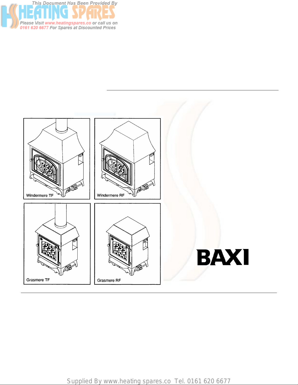
Baxi Windermere
Baxi Grasmere
Gas Stoves
Comp No 242300 - Iss 5 - 5/00
Installation and
Servicing Instructions
Page 2
Supplied By www.heating spares.co Tel. 0161 620 6677
Natural Gas Propane Gas
Baxi Windermere RF
G.C.No 32 075 26
Baxi Windermere TF
G.C.No 32 075 27
Baxi Grasmere RF
G.C.No 32 075 24
Baxi Grasmere TF
G.C.No 32 075 25
Baxi UK Limited is one of the leading
manufacturers of domestic heating products in
the UK.
Our first priority is to give a high quality service to
our customers. Quality is built into every Baxi
product -products which fulfil the demands and
needs of customers, offering choice, efficiency
and reliability.
To keep ahead of changing trends, we have
made a commitment to develop new ideas using
the latest technology - with the aim of continuing
to make the products that customers want to buy.
Baxi Windermere RF
G.C.No 32 075 28
Baxi Windermere TF
G.C.No 32 075 29
Baxi is also the largest manufacturing partnership
in the country. Everyone who works at the
company has a commitment to quality because,
as shareholders, we know that satisfied
customers mean continued success.
We hope you get a satisfactory service from Baxi.
If not, please let us know.
Baxi is a BS-EN ISO 9001
Accredited Company
Page 3
Supplied By www.heating spares.co Tel. 0161 620 6677
Contents – Page 3
Section
Page
1.0
2.0
3.0
4.0
5.0
6.0
7.0
8.0
9.0
10.0
11.0
12.0
13.0
Introduction
Technical Data
Site Requirements
Installation
Arranging the Coals
Commissioning the Stove
Checking for Spillage
Completion
Annual Servicing
Changing Components
Fault Finding
Short Parts List
Propane Models
4
5
6
9
11
13
14
15
16
20
23
24
25
The following items are packed with the appliance:-
Literature
Controls Cover
Coal Pieces (Windermere 2 types)
(Grasmere 3 types)
Ceramic
Closure Plate (All RF models)
Coal Guard (Grasmere only)
Page 4
Supplied By www.heating spares.co Tel. 0161 620 6677
1.0 Introduction – Page 4
Notice
Discolouration of wall surfaces
Most heating appliances generate warm air convection currents
and transfer heat to any wall surface against which they are
situated.
Some soft furnishings (such as blown vinyl wallpapers) may not
be suitable for use where they are subject to temperatures
above normal room levels and the manufacturer’s advice should
be sought before using this type of wall covering adjacent to any
heating appliance.
The likelihood of wall staining from convected air currents will be
increased in environments where high levels of tobacco smoke
or other contaminants exist.
1.1 Description
1. The Baxi Windermere RF and TF and Grasmere RF and
TF are gas fired stove - style appliances with heat inputs of
8.17 kW (27,876 Btu/h) and 6.5 kW (22,178 Btu/h)
respectively at maximum setting. They are designed to be
used on Natural Gas only at a setting pressure of 20mbar
on an installation with a governed meter. The appliances
are intended for heating and decorative purposes.
2. For details of Propane appliances see section 13.0
Propane Models.
3. They incorporate a safety feature in the form of a spillage
monitoring system which must not be adjusted or
bypassed.
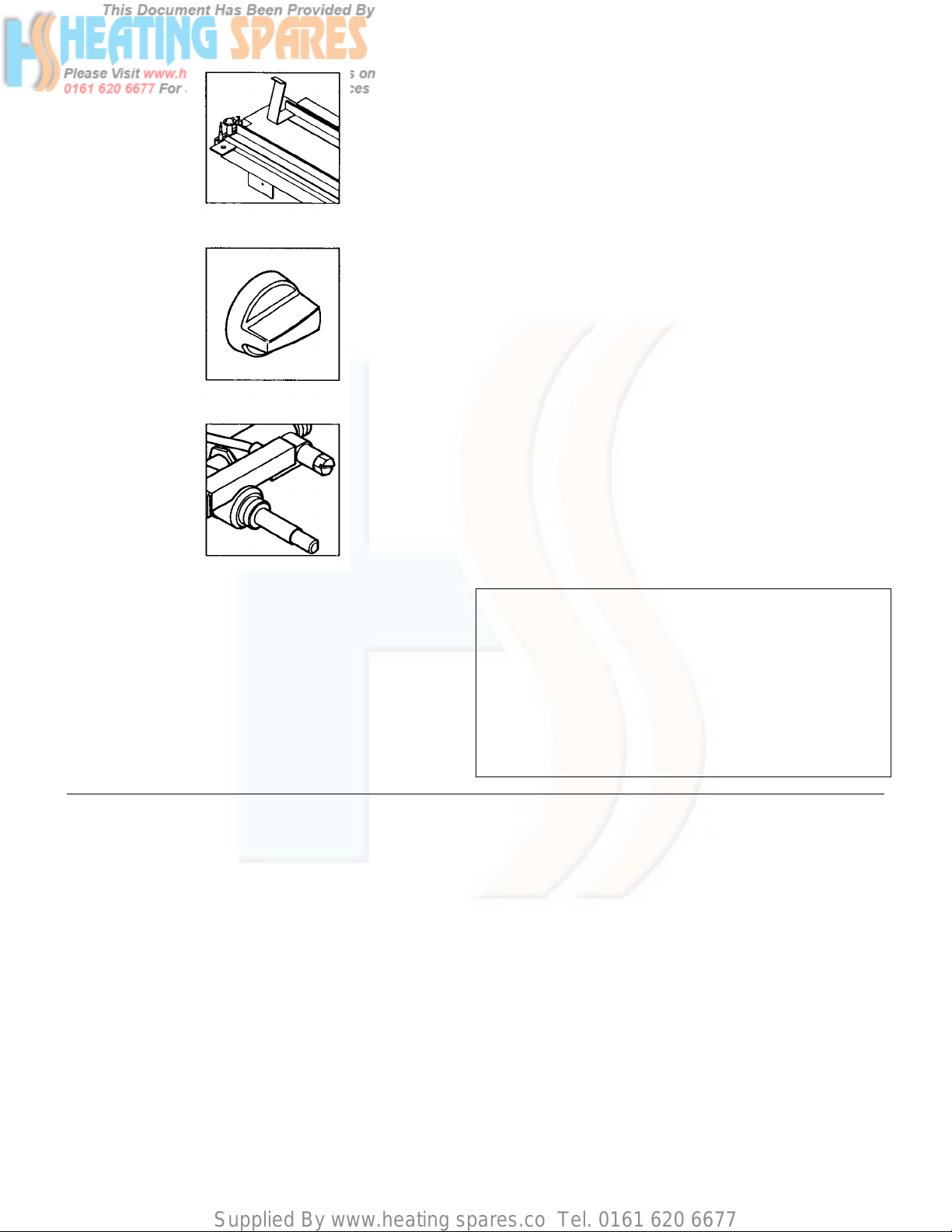
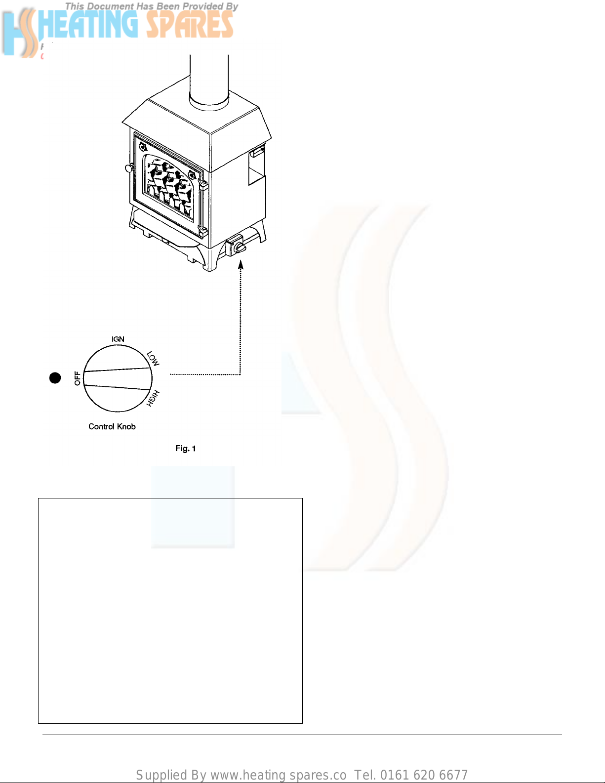
4. The stove is controlled by a knob which is positioned at the
lower right hand side of the appliance (Fig1). The knob has
four positions:
OFF IGN LOW HIGH
5. The pilot will be lit at IGN.
1.2 Installation
1. Prior to installation, ensure that the local distribution
condition (identification of the type of gas and pressure)
and the adjustment of the appliance are compatible.
2. The appliance is suitable for installation only in GB. and
I.E. and should be installed in accordance with the rules in
force. For Ireland install in accordance with l.S.813
“INSTALLATION OF GAS APPLIANCES”. The
installation must be carried out by a CORGI Registered
Installer or other competent person and be in accordance
with the relevant requirements of the current GAS
SAFETY (Installation and Use) REGULATIONS (as
amended), the BUILDING REGULATIONS issued by the
Department of the Environment, BUILDING STANDARDS
(Scotland) (Consolidation) REGULATIONS issued by the
Scottish Development Department and the LOCAL
BUILDING REGULATIONS. Where no specific
instructions are given, reference should be made to the
relevant BRITISH STANDARD CODES OF PRACTICE.
2. This appliance must be installed in accordance with
the manufacturers instructions and the rules in force
and only used in a suitably ventilated location.
3. Read the instructions before installing or using this
appliance.
1.3 Important Information
This product contains Refractory Ceramic Fibres (R.C.F.) which
are man-made vitreous silicate fibres. Excessive exposure to
these materials may cause temporary irritation to eyes, skin and
respiratory tract. Care must be taken when handling these
articles to ensure the release of dust or fibres is kept to a
minimum.
To ensure that the release of fibres from these articles is kept to
a minimum, during installation and servicing it is recommended
that a H.E.P.A. filtered vacuum is used to remove any dust, soot
or other debris accumulated in and around the appliance. This
should be performed before and after working on the
installation.
It is recommended that any replaced item(s) are not broken up
but sealed within heavy duty polythene bags and clearly labelled
“R.C.F. waste”. This is not classified as ‘hazardous waste” and
may be disposed of at a tipping site licensed for the disposal of
industrial waste.
Protective clothing is not required when handling these articles
but it is recommended that gloves are worn and the normal
hygiene rules of not smoking, eating or drinking in the work area
are followed and always wash hands before eating or drinking.
Page 5
Supplied By www.heating spares.co Tel. 0161 620 6677
2.0 Technical Data – Page 5
Grasmere Windermere
Category of Appliance I
2H
The stove is set for Gas Type G20 at 20mbar.
Category of Appliance I
2H
The stove is set for Gas Type G20 at 20mbar.
Heat Input High Low Heat Input High Low
kW 6.5 5 kW 8.17 5.6
Btu/h 22,178 17,060 Btu/h 27,876 19,107
Heat Output High Heat Output High
kW 4.96 kW 6.14
Btu/h 16,922 Btu/h 20,962
Inlet Setting Pressure Cold Inlet Setting Pressure Cold
mbar 9 ± 0.5 mbar 6.5 ± 0.5
in wg 3.6 ± 0.2 in wg 2.6 ± 0.2
Gas Connection 8mm OD tube, rigid or semi
rigid and 8mm compression
fitting at appliance inlet
Controls &
Safety system
Rotary gas tap with piezo
ignition to pilot.
Spillage monitoring system
Gas
Connection
Controls &
Safety system
8mm OD tube, rigid or semi rigid
and 8mm compression fitting at
appliance inlet
Rotary gas tap with piezo ignition
to pilot.
Spillage monitoring system
Gas Rate 0.63m3/h Gas Rate 0.80m3/h
(22.241 ft3/h) (24.01 ft3/h)
Lifting Weight RF TF Lifting Weight RF TF
38.2 kg 36.4 kg 54.1 kg 51.6 kg
Dimensions Height 555mm (RF) Dimensions Height 730mm (RF)
Height 580mm (TF) Height 758mm (TF)
Width 450mm Width 600mm
Depth 345mm Depth 410mm
Injector 82/600 Injector 82/850
B.S. Codes of Practice
STANDARD SCOPE
B.S. 5440: Pts 1 & 2 Flues & Air Supply.
B.S. 1251 Open Fireplace Components
B.S. 5871: Pt 2 & 3 Installation of inset live fuel effect &
B.S. 715 Specification for metal flue pipes,
B.S. 6391 Gas Installation.
B.S. 1289: Pts 1 & 2 Specification for precast & clay flues
decorative fuel effect appliances.
fittings etc.
and terminals.
Page 6
Supplied By www.heating spares.co Tel. 0161 620 6677
3.0 Site Requirements – Page 6
3.1 Fireplace Surround and Hearth
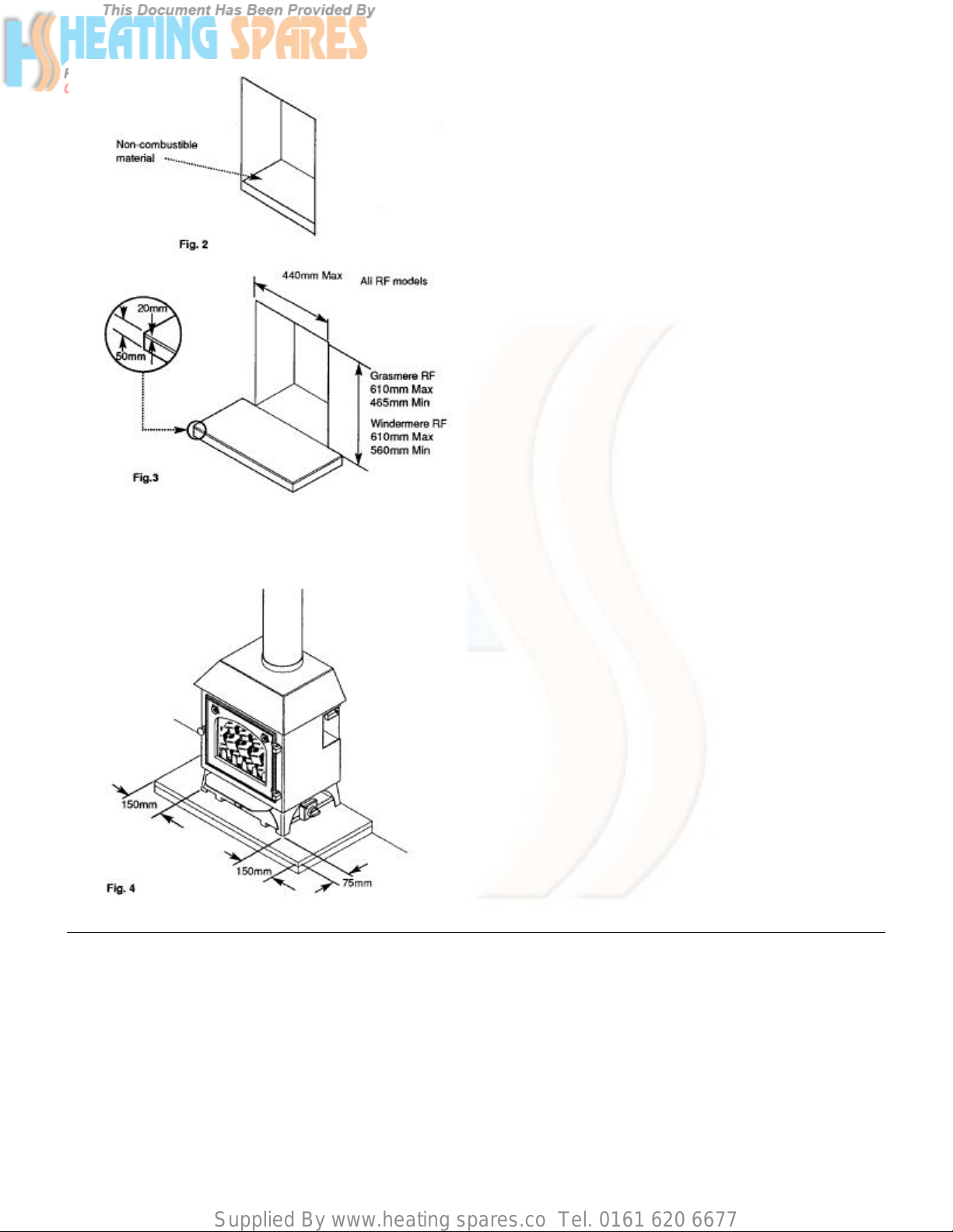
1. A hearth of non-combustible material must be provided
within the fireplace opening on which material the stove
stands (where applicable) (Fig. 2).
2. A non-combustible hearth must also be provided in
front of the fireplace opening. This must be a minimum
of 20mm thick, the top surface of the hearth should be
a minimum of 50mm above floor level (Fig. 3).
3. The hearth should extend at least 75mm in front of the
stove legs and 150mm either side of the stove (Fig. 4).
4. If a fire surround is to be used, it must have a minimum
rating of 300o C. Any gaps between the wall and
surround must be sealed.
5. On no account should the stove be fitted directly
onto a combustible floor or carpet.
3.2 Ventilation
Grasmere
1. No purpose provided ventilation is required for the
appliance, normal adventitious room ventilation being
sufficient.
Windermere
1. A permanent air vent of 100cm2 minimum is required.
The permanent vent may be directly into the room in
which the appliance is installed, or to an adjacent room
which has a vent to outside of at least the same area.
Page 7
Supplied By www.heating spares.co Tel. 0161 620 6677
3.0 Site Requirements – Page 7
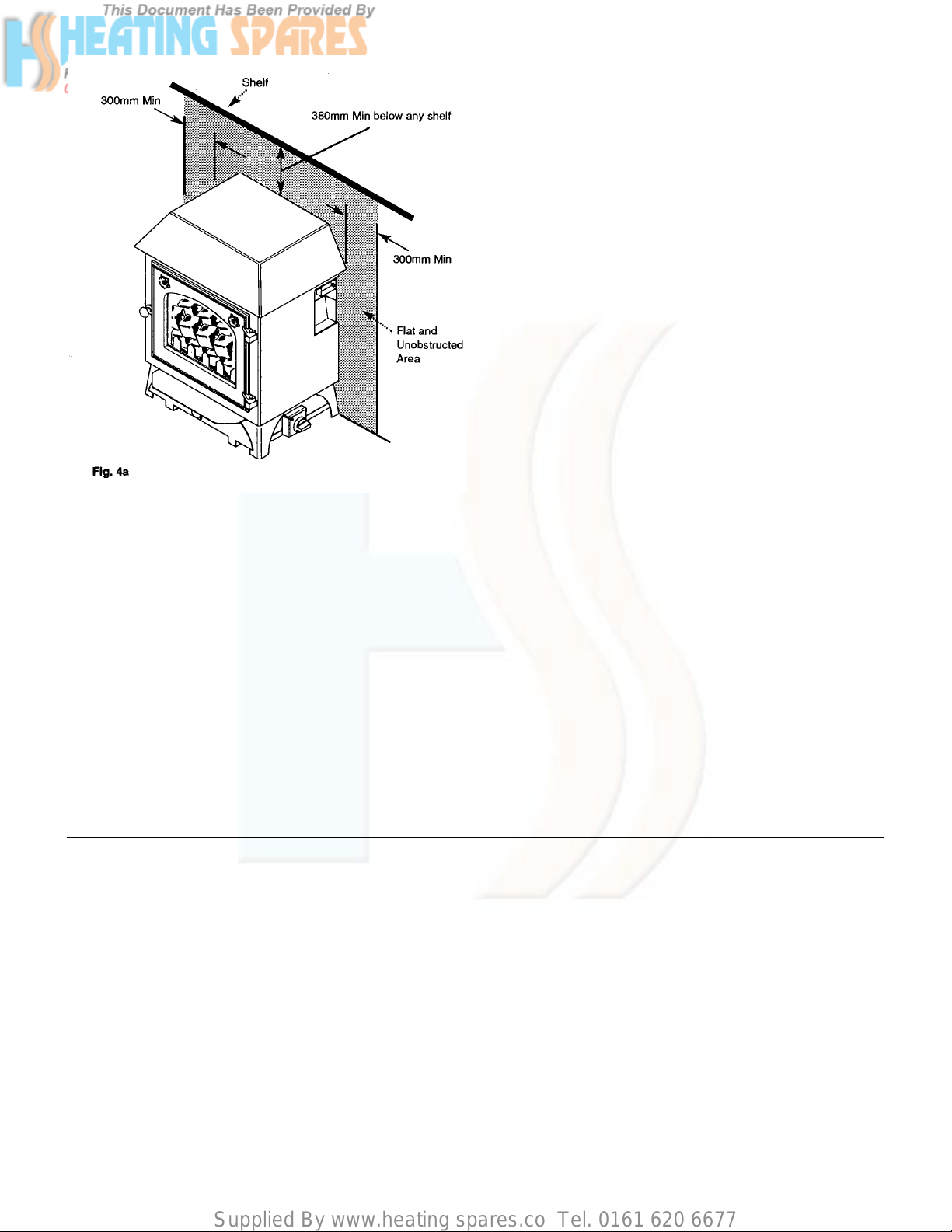
3.3 Clearances (Fig. 4a)
1. Any combustible material must be at least 300mm
away from the stove or flue pipe.
2. The wall or surround to each side of the stove must be
flat and unobstructed for at least 300mm.
3. Any shelf above the stove must be at least 300mm
away from the stove or flue pipe.
4. No curtains should be within 380mm of the stove or flue
pipe when they are in any position.
3.4 Flues
1. The chimney or flue system must be suitable for a
Class 1 or Class 2 appliance, as defined by the Building
Regulations.
2. It must have an internal diameter of minimum 125mm
or equivalent.
3. Generally brick or block built chimneys, pre-cast flues
or fabricated flues will meet these requirements.
4. The flue must be a minimum of 4m high, measured
from the hearth to the point of termination. The flue
must befitted with a suitable pot or cowl with an internal
diameter not less than 125mm.
5. Any obstructions, damper plates or flue restrictors must
be removed before installation.
6. If the flue is not sound or in good condition a liner of not
less than 125mm internal diameter and conforming to
BS 715 must be fitted.
7. The flue must be swept before installation and any
underfloor air supply beneath the stove sealed off.
8. It is essential that there is a positive pull up the flue or
chimney. If there is not, DO NOT fit the stove. Seek
expert advice before continuing with the installation.
Page 8

Supplied By www.heating spares.co Tel. 0161 620 6677
3.0 Site Requirements – Page 8
3.5 Gas Supply & Connection
1. Determine where the gas supply is to be connected to
the appliance. This may be done from either the left or
right side, from the front, or a concealed fitting from the
rear.
Turn off any appliances that are fed by the meter and
isolate the gas supply by turning off at the meter.
2. The inlet elbow of the stove will accept 8mm OD tubing
(Fig. 5).
3. A suitable isolating cock and disconnecting union
should be always be fitted in the supply feed to the fire
to facilitate servicing.
Page 9

Supplied By www.heating spares.co Tel. 0161 620 6677
4.0 Installation – Page 9
4.1 Initial Preparation
1. After unpacking the appliance, carefully remove all
items from inside the stove.
2. Care must be exercised when handling the appliance to
prevent damage to the paint finish. Avoid touching the
appliance with greasy or dirty hands
4.2 Top Flue Outlet Stoves
1. These models must be connected to the flue or
chimney with a suitable length of 125mm diameter
vitreous enamelled flue pipe fitted inside the spigot on
top of the stove.
2. The flue pipe must be fitted through a register plate of
fireproof material. All joints must be sealed.
4.3 Rear Flue Outlet Stoves (Fig. 6)
1. These models may be fitted to a builders opening, class
2 starter block or flue starter box, using the closure
plate supplied.
2. The closure plate must be sealed along all edges. No
air relief vent is necessary.
3. If necessary the closure plate can be cut down
providing the fireplace opening is fully covered.
4. A minimum clearance of 50mm is required between the
end of the flue spigot and rear face of the flue or
opening.
5. The rear of the stove must not touch the closure plate,
a gap of at least 15mm being required. The flue spigot
collar ensures this dimension.
Page 10

Supplied By www.heating spares.co Tel. 0161 620 6677
4.0 Installation – Page 10
4.4 Fitting the Stove
1. Position the stove in the installation, and in the case of
top flue outlet models, connect the flue pipe.
2. When positioning the stove, care must be exercised not
to mark the hearth.
3. Purge the gas supply and connect it to the stove inlet
elbow (Fig. 7). Check for gas soundness with leak
detection fluid (to BS 6891).
Page 11

Supplied By www.heating spares.co Tel. 0161 620 6677
5.0 Arranging the Coals – Page 11
5.1 Arranging the Coals
It is important that all the coals are used and arranged
as shown in order to achieve the desired flame picture.
CAUTION: The coals are extremely fragile and must be
handled accordingly. To avoid soiling ones hands,
gloves should be worn and any inhalation of the dust
should be avoided. Keep the coals away from children at
all times. Never use coals other than those supplied or
Genuine Baxi Spare Parts. Never put additional coals on
the stove. Please read section 1.3 Important Information.
5.2 Grasmere
1. Remove the coal guard (Fig. 8).
2. Carefully unpack the ceramic base (Fig. 9). Locate this
in the stove, resting on the two supports (Fig. 10 & 13).
3. Replace the coal guard (Fig. 10).
4. Three types of coal are supplied with the Grasmere, 13
small coals with location holes, 14 standard small coals
and 2 large coals.
5. Take the 13 small coals and locate them on the pegs
on the ceramic base (Fig. 11).
6. The two large coals should be placed between the
outer two coals on the back row and the ceramic
sidecheeks (Fig. 12).
7. Place the remaining 14 standard coals over the gaps
between the other small coals (Fig. 13).
8. Close the appliance door and secure it with the brass
knob (Fig. 14).
Page 12

Supplied By www.heating spares.co Tel. 0161 620 6677
5.0 Arranging the Coals – Page 12
5.3 Windermere
1. Carefully unpack the ceramic base and place it
centrally over the burner (Fig. 15).
2. Two types of coal are supplied with the Windermere, 24
small coals with location holes, 18 large coals.
3. Take the 24 small coals and locate them on the pegs
on the ceramic base (Fig. 16).
4. Place six of the large coals between the middle row and
back row and a further six between the middle and front
row (Fig. 17).
5. The final six large coals should be placed between the
door of the stove and the ceramic base (Fig. 18).
6. Close the appliance door and secure it with the brass
knob (Fig. 19).
5.4 Cleaning
1. Carefully clean the stove with a soft lint free duster or
cloth. DO NOT USE any abrasive cleaning agents,
solvents or similar when cleaning.
2. Clean any debris from around and underneath the
stove.
Page 13

Supplied By www.heating spares.co Tel. 0161 620 6677
6.0 Commissioning the Stove – Page 13
6.1 Checking Gas Soundness
1. Turn on the gas supply and check for gas soundness
with leak detection fluid (to BS 6891).
6.2 Checking Operation of the Stove
1. Remove the screw from the pressure test point on the
gas tap (adjacent to the control knob) and fit a pressure
gauge (Fig. 20).
2. Purge the air from the appliance by pushing in the
control knob and rotating to the ignition position (Fig.
21). Allow the air in the pipework to be purged, and
then rotate the knob further to operate the piezo igniter.
The pilot should light.
3. Once the pilot is established push the control knob in
and turn to the HIGH setting. Check the setting
pressure. (Setting pressure detail found in Section 2.0
Technical Data.)
4. Turn the control knob to the OFF position, disconnect
the pressure gauge and refit the pressure test point
sealing screw.
6.3 Spillage Monitoring Device (Fig. 22)
1 The stove incorporates a spillage monitoring device.
This will cut off the gas supply in the event of spillage of
combustion products into the room.
2. In the event of this occuring there is a reset procedure.
Wait for 10 minutes before trying to reset the stove.
3. Unscrew the cap off the reset device and press in the
red button with a small screwdriver or similar
instrument.
4. Relight the stove as previously described. If this is not
possible, wait a further 5 minutes before pressing the
red button. If this fails, wait until the stove is completely
cool and reset it.
5. If the stove cannot be re-set or the spillage monitoring
device is frequently activated the flue condition must be
investigated.
WARNING: The spillage monitoring device must not be
adjusted in any way. The spillage monitoring device
must not be altered so that it will not operate or be
bypassed in any way. Only use genuine Baxi spare
parts.
Page 14

Supplied By www.heating spares.co Tel. 0161 620 6677
7.0 Checking for Spillage – Page 14
7.1 Checking for Spillage
CAUTION - Whilst checking for spillage care must be
taken to avoid touching hot panels.
1. Before starting the test, close all doors and windows.
2. Operate the stove from cold at maximum input.
3. After approximately 5 minutes check for spillage.
4. Insert a lighted smoke match in the draught diverter at
the left hand side. The match should be positioned
35mm from the top edge of the diverter (Fig. 23). All the
smoke should be drawn into the diverter. If not, wait a
further 5 minutes and repeat the test.
5. If the test is successful repeat with any extractor fan on.
If a connected room has an extractor fan, the test
should be repeated with this fan on and any connecting
doors open.
6. If spillage occurs and the problem cannot be rectified
the stove must be isolated until the problem is resolved.
7.2 Possible causes of Spillage
1. The smoke match may have been positioned
incorrectly, resulting in the smoke being picked up by
hot convected air currents.
2. The flue installation may be unsound.
3. Down draughts may be present.
4. Flue blockages.
5. Rear flue - closure plate not sealed, stove not close
enough to closure plate.
6. Top flue – flue pipe not sealed to stove spigot.
Page 15

Supplied By www.heating spares.co Tel. 0161 620 6677
8.0 Completion – Page 15
8.1 Completion
1. Unpack the controls cover and place it centrally
underneath the stove (Fig. 24).
2. These instructions and the users instructions should be
handed to the customer. At the same time the customer
should be shown how to operate the stove safely and
efficiently.
3. The need for annual servicing should be emphasised
and the returning of the guarantee card advised.
Page 16

Supplied By www.heating spares.co Tel. 0161 620 6677
9.0 Annual Servicing – page 16
9.1 Maintenance
IMPORTANT: It is possible that some soot may be
deposited on the coals after use. This is acceptable
providing it is not allowed to accumulate.
CAUTION: The coals are extremely fragile and must be
handled accordingly. To avoid soiling ones hands,
gloves should be worn and any inhalation of the dust
should be avoided. Keep the coals away from children at
all times. Never use coals other than those supplied or
Genuine Baxi Spare Parts. Never put additional coals on
the stove. Please read section 1.3 Important Information.
1. Servicing should be carried out regularly by a
competent person in accordance with the relevant
regulations, to ensure the safe and correct operation of
the appliance.
2. Before commencing any service or replacement of
parts, turn off the gas supply to the stove and ensure
that the stove is cold.
3. After servicing, check for gas soundness.
4. When ordering spare parts please quote appliance
name and serial number. These can be found on the
data badge which is located by removing the controls
cover (Fig. 25). The badge is behind the cover and
fixed to the burner.
5. At least once a year check for debris in the catchment
area behind the stove (RF models) and in the flueway.
6. If soot has accumulated in the flue or catchment area,
check to establish the cause. Rectify and clean flue or
chimney accordingly.
7. The coals may be removed for cleaning. The coals are
delicate and should be handled carefully. Gently brush
with a soft brush to remove dust or deposits.
8. Examine the coals for signs of cracking and replace if
necessary.
IMPORTANT: See coal layout procedure
(Section 5.0 Arranging the Coals) before attempting to
replace coals.
9. Do not clean pilot jet or injectors using pins or wire.
Page 17

Supplied By www.heating spares.co Tel. 0161 620 6677
9.0 Annual Servicing – Page 17
9.2 Preparation
1. For reasons of safety and economy it is important to
service the stove annually.
WARNING: Isolate the gas supply to the appliance
before servicing.
2. For Grasmere models see section 9.3 Grasmere.
3. For Windermere models see section 9.4 Windermere.
9.3 Grasmere
1. Unscrew the brass door knob and open the door (Fig.
26).
2. Remove the coal guard (Fig. 27) and remove all the
coals.
3. Manoeuvre the ceramic base (Fig. 28) out of the stove
and place carefully to one side.
4. Remove the two sidecheeks, noting their orientation
(Fig. 29).
5. Undo the screw and nut retaining the pilot shield
bracket and remove the bracket (Fig. 30).
6. Undo the disconnecting union on the gas supply.
7. Pull the control knob off the tap and undo the screw
retaining the plate (Fig. 31).
8. Undo the brass locknut holding the tap to the mounting
bracket (Fig. 31).
9. Undo the screw and remove the data badge plate (Fig.
32).
10. Disconnect the two leads from the spillage monitoring
device (Fig. 33).
11. Carefully manoeuvre the burner/controls assembly out
of the stove (Fig. 32).
Page 18

Supplied By www.heating spares.co Tel. 0161 620 6677
9.0 Annual Servicing – Page 18
9.4 Windermere
1. Unscrew the brass knob and open the door (Fig. 34).
2. Remove all the coals and manoeuvre the ceramic base
out of the stove and place carefully to one side (Fig. 35
& 36).
3. Undo the disconnecting union on the gas supply.
4. Pull the control knob off the tap and undo the screw
retaining the plate (Fig. 38).
5. Undo the brass locknut holding the tap to the mounting
bracket (Fig. 38).
6. Disconnect the two leads from the spillage monitoring
device (Fig. 39).
7. Carefully manoeuvre the burner/controls assembly out
of the stove (Fig. 40).
Page 19

Supplied By www.heating spares.co Tel. 0161 620 6677
9.0 Annual Servicing – Page 19
9.5 Cleaning the Pilot (Fig. 41)
1. Undo the feed pipe from the pilot injector and pull the
lead off the ignition electrode.
2. Undo the two screws holding the pilot assembly
retaining plate. Remove the plate and withdraw the
electrode and pilot burner. Note the orientation of the
pilot burner outlet ports.
3. Pull the pilot injector from the burner and clean
carefully. Do not use pins or wires
4. Clean the pilot burner and electrode.
9.6 Cleaning the Burner and Injector
(Fig. 42)
1. Undo the screw retaining the injector cover to the
injector mounting plate and remove the cover. Undo the
nut on the injector feed pipe at the injector.
2. Remove the two screws securing the injector mounting
plate to the burner and undo the locknut retaining the
injector to the plate.
3. Carefully clean the injector with a soft brush.
4. Carefully brush the burner and ceramic inlays. Care
must be taken not to damage the inlays.
9.7 Completing Servicing
1. Examine the thermocouple and replace if necessary
(Fig. 41).
2. Clean any dirt and debris from the combustion box,
builders opening and the hearth under the stove.
Please read section 1.3 Important Information.
3. Reassemble the stove in reverse order of dismantling.
On RF models reseal the closure plate and reposition
the stove at least 15mm away from the plate.
4. Recommission the stove as described in section 6.0
Commissioning the Stove.
Page 20

Supplied By www.heating spares.co Tel. 0161 620 6677
10.0 Changing Components – Page 20
10.1 Changing Components
WARNING: Before changing any components, ensure
that the stove is cool and that the gas supply is isolated.
10.2 Spillage Monitoring Device
(Figs. 43 & 44)
1. Undo the nut and screw holding the monitoring device
sensor bracket to the draught diverter.
2. Withdraw the sensor from the bracket.
3. Pull the two wires off the sensor body and undo the
screws holding the body to the appliance.
4. Remove the spillage monitoring device from the
appliance.
5. Refit the new device in reverse order, carefully routing
the capillary so as it does not touch any hot panels.
WARNING: The spillage monitoring device must not be
adjusted in any way. The spillage monitoring device
must not be altered so that it will not operate or be
bypassed in any way. Always use a Genuine Baxi Spare
Part.
TO CHANGE ANY GAS CONTROL COMPONENTS. IT IS
NECESSARY TO REMOVE THE COMPLETE CONTROLS
ASSEMBLY. SEE SUB-SECTION 9.2 PREPARATION OF
9.0 ANNUAL SERVICING
Page 21

Supplied By www.heating spares.co Tel. 0161 620 6677
10.0 Changing Components – Page 21
10.3 Gas Tap, Igniter and FFD
NOTE: The tap incorporates a flow setting device on its
outlet connection. This is factory set and must not be
adjusted.
1. Pull the electrode lead off the electrode (Fig. 45).
2. Undo the thermocouple nut from the interrupter unit and
pull off the two leads (Fig. 46).
3. Undo the pilot feed nut and the gas inlet and outlet nuts
from the tap assembly (Fig. 46).
4. Note the orientation of all the pipes and remove them.
5. Remove the gas tap (Fig. 46).
6. Remove the interrupter unit from the gas tap (Fig. 46).
7. Refit in reverse order of dismantling, ensuring that the
thermocouple nut is done up tight in the interrupter unit.
10.4 Injector (Fig. 47)
1. Undo the screw retaining the injector cover to the
injector mounting plate and remove the cover.
2. Undo the nut on the injector feed pipe at the injector.
3. Remove the two screws securing the injector mounting
plate to the burner and undo the locknut retaining the
injector to the plate.
4. Fit the new component and reassemble in reverse
order of dismantling.
Page 22

Supplied By www.heating spares.co Tel. 0161 620 6677
10.0 Changing Components – Page 22
10.5 Electrode (Fig. 48)
1. Pull the lead off the electrode and undo the two screws
holding the pilot retaining plate.
2. Note the orientation of the electrode, withdraw it and
refit the new component in reverse order of dismantling.
10.6 Thermocouple (Figs. 48 & 49)
1. Undo the thermocouple nut from the interrupter unit and
remove the two screws holding the pilot retaining plate.
2. Remove the thermocouple and shape the new one in a
similar manner to the original.
3. Fit the new component in reverse order of dismantling.
10.7 Pilot Burner and Injector (Fig. 48)
1. Undo the pilot feed pipe nut from the pilot injector.
2. Undo the two screws holding the pilot assembly
retaining plate, noting the orientation of the pilot burner
outlet ports.
3. Withdraw the pilot injector and burner. The injector can
now be removed from the burner.
4. Replace either or both components as required and
reassembly in reverse order of dismantling.
10.8 Burner (Fig. 50)
1. Remove all other control components as described in
sections 10.3 through to 10.7.
2. Fit all the previously removed control components to
the new burner.
3. Reassemble all components in reverse order and
recommission the appliance.
Page 23

Supplied By www.heating spares.co Tel. 0161 620 6677
11.0 Fault Finding – Page 23
11.1 Fault Finding
Page 24

Supplied By www.heating spares.co Tel. 0161 620 6677
12.0 Short Parts List – Page 24
12.1 Short Parts List
Key
No.
G.C. No
Description
Manuf ’s
Part No.
19a
16
39
35
20/23
28
22
25/29
47
42
45
41
46
44
3
2
9
10
39/43
E37 444
E39 307
E37 468
E39 314
E37 448
E37 452
E39 310
E37 450
E37 475
E39 327
E37 473
E39 326
E37 474
E37 472
E37 425
E37 424
E37 433
E39 300
E37 471
Main Burner - Grasmere
Main Burner – Windermere
Gas Tap-inc. Lead – Grasmere
Gas Tap-inc. Lead - Windermere
Pilot Burner Kit
Main Injector - Grasmere
Main Injector – Windermere
Spillage Monitoring Device
Burner Inlays - Grasmere
Burner Inlays - Windermere
Base - Grasmere
Base - Windermere
Kit- Coals - Grasmere
Side Cheeks - Grasmere
Rear Ceramic - Grasmere
Top Ceramic - Grasmere
Door Glass Kit - Grasmere
Door Glass Kit - Windermere
Control Knob
242675
242676
242677
242678
242679
242681
242682
242683
242684
242685
242686
242687
242690
242691
242692
242693
242694
242695
242696
4/7
19/22
18/21
40
E37 431
E37 447
E37 445
E39 324
Brass Door Knob
Thermocouple - Stove
Electrode - Stove
Kit -Loose Coals - Windermere
242697
242698
242699
242700
Page 25

Supplied By www.heating spares.co Tel. 0161 620 6677
13.0 Propane Models – Page 25
13.1 Windermere Propane Models
1. Most aspects of the Propane Models are the same
as Natural Gas, with the exception of the following:
The gas type is G31 (Propane)
The supply pressure is 37mbar
(Max) Heat Input 7.5kW (25,590 Btu/h)
(Min) Heat Input 5.2kw (17,742 Btu/h)
(Max) Heat Output 5.6kw (19,116 Btu/h)
Burner Pressure 28.5mbar (11.4 in wg)
2. The following spares components differ from natural
gas models:
Injector 242704
Ceramic burner inlay 242705
Burner 242706
Pilot Injector 242707
3. This appliance is designed for use on Propane
and must not be used with any other gas.
Click here for Helplines
 Loading...