

Baxi Gallery BR660VA Installer's Manual
5112253/01
INSTALLER GUIDE
owner
THIS APPLIANCE IS SUITABLE ONLY FOR INSTALLATION IN THE UNITED
For technical advice firstly contact your retailer. If further advice is required then call
Model BR660VA
Heat Engine
POWER FLUE INSET GAS FIRE
(GC No. 32-032-44)
THIS APPLIANCE IS FOR USE WITH NATURAL GAS (G20).
WHEN CONVERTED USING CONVERSION KIT NO. 0591149 THIS
APPLIANCE IS FOR USE WITH PROPANE GAS (G31).
KINGDOM (GB) AND THE REPUBLIC OF IRELAND (IE).
0161703 8157 for The Midlands and North or
01462 813 138 for The South.
INSTALLER: Please leave this guide with the
© Baxi Heating U.K. Ltd.
This gas fire is CE Approved and designed to meet the appropriate British Standards
This fire has been manufactured to the highest standards of quality and excellence and
was manufactured under a BS EN ISO 9001 quality system accepted by the British
The manufacturer is a member of the Society of British Gas Industries which works to
Because our policy is one of constant development and improvement, details may vary slightly from those
INSTALLER GUIDE
Safety First.
and Safety Marks.
Quality and Excellence.
Standards Institute.
The Highest Standards
ensure high standards of safety, quality and performance.
Careful Installation
The manufacturer is a CORGI registered company. This gas fire must be
installed by a competent CORGI Registered Installer in accordance
with our Installer Guide and should not be fitted directly on to a
carpet.
Baxi Fires Division, Erdington, Birmingham B24 9QP
given in this publication
Page 2

INSTALLER GUIDE
CONTENTS
Section Heading Page
1. SAFETY 4
2. APPLIANCE DATA 4
3. GENERAL INSTALLATION REQUIREMENTS 5
4. APPLIANCE DIMENSIONS 12
5. UNPACKING 14
6. PREPARING FOR INSTALLATION 16
7. WALL PREPARATION 16
7.1 General. 16
7.2 Brick, stone etc. building. Main case in front of wall 17
7.3 Brick, stone etc. building. Main case recessed into wall. 17
7.4 Lintel installation. 18
7.5 Timber frame building. Firebox in front of wall. 19
7.6 Wall preparation for flue tube. 19
7.7 Core drilling. 19
7.8 Hammer and chisel cutting. 19
7.9 Combustible walls (wood, fibreboard, plasterboard etc.). 20
7.10 Fixing the appliance in position. 21
7.11 Prepare flue assembly. 22
8. INSTALLATION OF ELECTRICS, FIREBOX AND FAN BOX 22
8.1 Securing firebox to wall - cable retention. 23
8.2 Securing firebox to wall using fixing brackets. 23
8.3 Fan box installation. 24
8.4 Electrical installation 26
8.5 Refitting the burner unit. 27
8.6 Electrical test. 28
8.7 Terminal guarding. 29
9. GAS SUPPLY INSTALLATION 29
9.1 Gas supply connection. 29
9.2 Preliminary burner checks. 29
9.3 Check reference pressure . 30
10. FITTING THE CERAMIC FUEL EFFECT 31
11. FITTING THE FASCIA 31
12. CHECKS 32
13. FINAL REVIEW 34
14. SERVICING PARTS AND REPLACEMENT 34
Page 3

When lifting always keep your back straight. Bend your legs and not your back.
Always grip with the palm of the hand. Do not use the tips of fingers for support.
This product uses fuel effect pieces, gaskets and a burner compartment rear wall
silicate fibres. Excessive exposure to these materials may cause irritation to eyes,
handling these articles to ensure that the release of dust is kept to a minimum. To
and after working on the fire. When replacing these articles we recommend that
the replaced items are not broken up, but are sealed within a heavy duty polythene
bag, clearly labelled as RCF waste. This is not classified as “hazardous waste” and
Protective clothing is not required when handling these articles, but we recommend
you follow the normal hygiene rules of not smoking, eating or drinking in the work
INSTALLER GUIDE
1. SAFETY
Installer
Before continuing any further with the installation of this appliance please read the
following guide to manual handling:
! The lifting weight of this appliance is as below:
Heat engine and convector box asembly 9.15 kg.
Fan unit assembly 5.97 kg.
! One person should be sufficient to lift the fire. If for any reason this weight is
considered too heavy then obtain assistance.
!
! Avoid twisting at the waist. It is better to reposition your feet.
! Avoid upper body/top heavy bending. Do not lean forward or sideways whilst
handling the fire.
!
! Always keep the fire as close to the body as possible. This will minimise the
cantilever action.
! Use gloves to provide additional grip.
! Always use assistance if required.
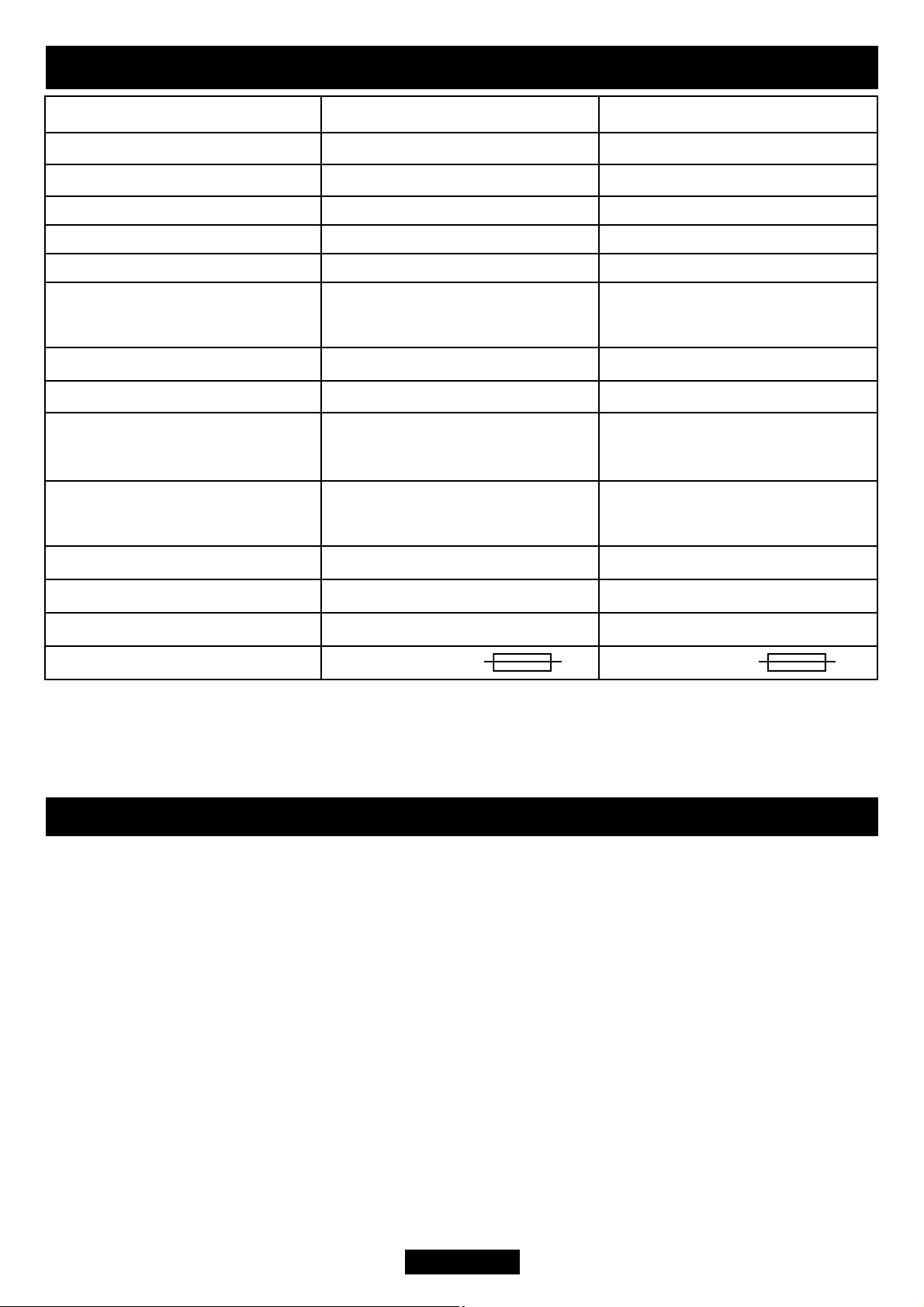
2. APPLIANCE DATA
containing Refractory Ceramic Fibres (RCF), which are man-made vitreous
skin and respiratory tract. Consequently, it is important to take care when
ensure that the release of fibres from these RCF articles is kept to a minimum,
during installation and servicing we recommend that you use a HEPA filtered
vacuum to remove any dust and soot accumulated in and around the fire before
may be disposed of at a tipping site licensed for the disposal of industrial waste.
area and always wash your hands before eating or drinking.
This appliance does not contain any component manufactured from asbestos or
asbestos related products.
Page 4
The appliance data label is located on a plate at the base of the fire. This can be seen by
For the user’s protection, in the United Kingdom it is the law that all gas appliances are
installed by competent persons in accordance with the current edition of the Gas Safety
(Installation and Use) Regulations. Failure to install the appliance correctly could lead
to prosecution. The Council for the Registration of Gas Installers (CORGI) requires its
In the United Kingdom, all electrical supply installation must be installed in accordance
Environment and the Welsh Office or the Building Standards (Scotland) (Consolidation)
INSTALLER GUIDE
3.6kW (12,280Btu/h)
34.9 ± 0.75 mbar (14.0 ±
Piezo Electric. Integral with
Gas
Inlet Pressure 20mbar 37mbar
Input - Max. (Gross) 6.0kW (20,500Btu/h) 6.1kW (20,800Btu/h)
Input - Min. (Gross) 2.2kW (7,500Btu/h) 3.6kW (12,280Btu/h)
Output - Max. 3.12kW (10,600Btu/h)
Output - Min 1.1kW (3,750Btu/h) 1.8kW (6,140Btu/h)
14.9 ± .75mbar (6.0 ± 0.3in
Inlet Test Pressure (Cold)
Gas Connection 8mm pipe 8mm pipe
Burner Injector Bray Cat. 18 Size 400 Bray Cat. 18 Size 170
Pilot & Atmosphere Sensing
Device
Piezo Electric. Integral with
Ignition
Aeration Non-adjustable Non-adjustable
Natural (G20) Propane (G31) *
w.g.)
SIT Ref. NGOP9044 SIT Ref. OPLPG9222
Gas Tap
0.3in w.g.)
Gas Tap
Electrical Supply 230V ~ 50Hz AC 230V ~ 50 Hz AC
Fan motor rating 55W 55W
Fuse rating 3A 3A
* When converted using Kit 0591149.
removing the lower firefront and casting.
3. GENERAL INSTALLATION REQUIREMENTS
3.1 The installation must be in accordance with these instructions.
members to work to recognised standards.
with the current edition of the IEE Wiring Regulations (BS7671).
In the United Kingdom the installation must also be in accordance with:
a) All the relevant parts of local regulations.
b) The current edition of the Building Regulations issued by the Department of the
Regulations issued by the Scottish Development Department.
Page 5

Electrical isolation of the unit should be by means of a switched 3A fuse spur that
should be readily accessible to the user, easily identifiable and sited within reach of the
As supplied, the appliance is suitable for homes constructed of brick, stone, etc.,
the appliance can be installed into walls up to a maximum thickness as shown below.
Installation to a timber framed building should be in accordance with the relevant
sections of Institute of Gas Engineers publication IGE/UP/7 “Gas installations in timber
conglomerate marble hearths are considered as non-combustible). The fire box must be
mounted on a non-combustible surface level with the hearth. The hearth must project at
least 300mm forward of the fire box front and be at least 625mm wide (see illustrations
The surface of the hearth must be sufficiently flat to enable the bottom of the fascia /
INSTALLER GUIDE
c) All relevant codes of practice.
The relevant parts of the current editions of the following British Standards:-
BS 5440 Part 1
BS 5871 Part 2 & 3
BS 6891
In the republic of Ireland the installation must also conform with:
a) The current edition of IS 813 “Domestic gas installations”
b) All relevant national and local rules in force.
c) The current ETCI National Rules for Electrical Installation.
Where no specific instructions are given, reference should be made to the relevant
British Standard Code of Practice.
3.1.2
mains cable provided. It should only connect this appliance.
3.1.3 This fire is a fan flued appliance for installation on an outward facing wall of a
conventional home which does not have a purpose built flue or chimney.
3.1.4
If the fire box is in front of the finished wall surface: 600mm (23 5/8in) max.
These dimensions are from the finished internal wall surface (including any surround
material) to the external wall surface.
3.1.5
frame buildings”. Please note that advice should be sought before installing in a
timber frame building since the alterations required may nullify any NHBC cover
relating to the property. If in doubt, guidance should be requested from your local
authority planning or building department.
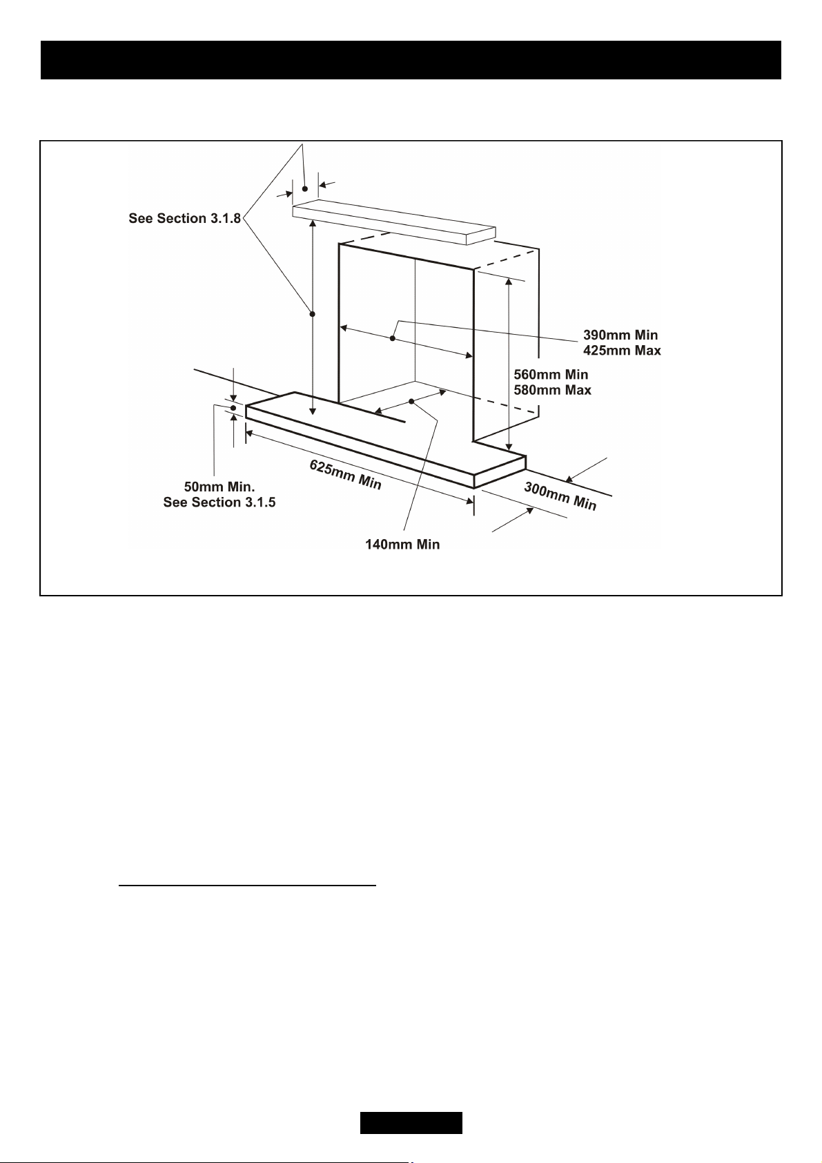
This appliance must be mounted with a non-combustible hearth (See figure 1) (N.B.
in “wall preparation” section). The hearth material must be at least 12mm thick. The
periphery of the hearth (or fender) should be at least 50mm above floor level to
discourage the placing of carpets or rugs over it.
Page 6
firefront to be aligned horizontally. Any excessive unevenness (uneven tiles, Cotswold
appliance is to be fitted against a wall with combustible cladding or skirting board, such
The appliance can be fitted to a purpose made proprietary class “O” 150°C surround.
If fitting a fascia that has a firefront designed to sit on a hearth, a reduced depth hearth
INSTALLER GUIDE
stone, etc.) should be rectified.
Figure 1. Hearth and recess requirements
3.1.6 The appliance must not stand on combustible materials or carpets.
The appliance must not be fitted directly against a combustible wall. If the
materials must be removed from the area covered by the fascia of the appliance. We
suggest that the actual fascia is used as a template to mark the area for combustible
cladding removal.
The opening in the surround or wall recess for the fire box must be within the limits
shown in figure 1.
3.1.7. ‘Hole-in-the-wall’ Installations
It is recommended that a hearth should be installed as in figure 1.
is recommended. This is necessary to support the firefront. The heat engine must be
installed so that distance from the base of the fireplace opening in the wall to the
finished floor level shall be at least 88 mm.
If fitting a fascia that does not have a separate firefront and a hearth is not fitted, the
Page 7
heat engine must be installed so that distance from the base of the fireplace opening in
covered by the fire box top and side flanges to ensure a good seal. The minimum height
heat. They may scorch or become discoloured when close to a heating appliance. Please
The appliance must not be installed in any room that contains a bath or shower or
INSTALLER GUIDE
the wall to the finished floor level shall be at least 88 mm.
3.1.8 The front face of the wall should be reasonably flat over the area that will be
from the top surface of the hearth to the underside of any shelf made from wood or
other combustible materials is as follows:-
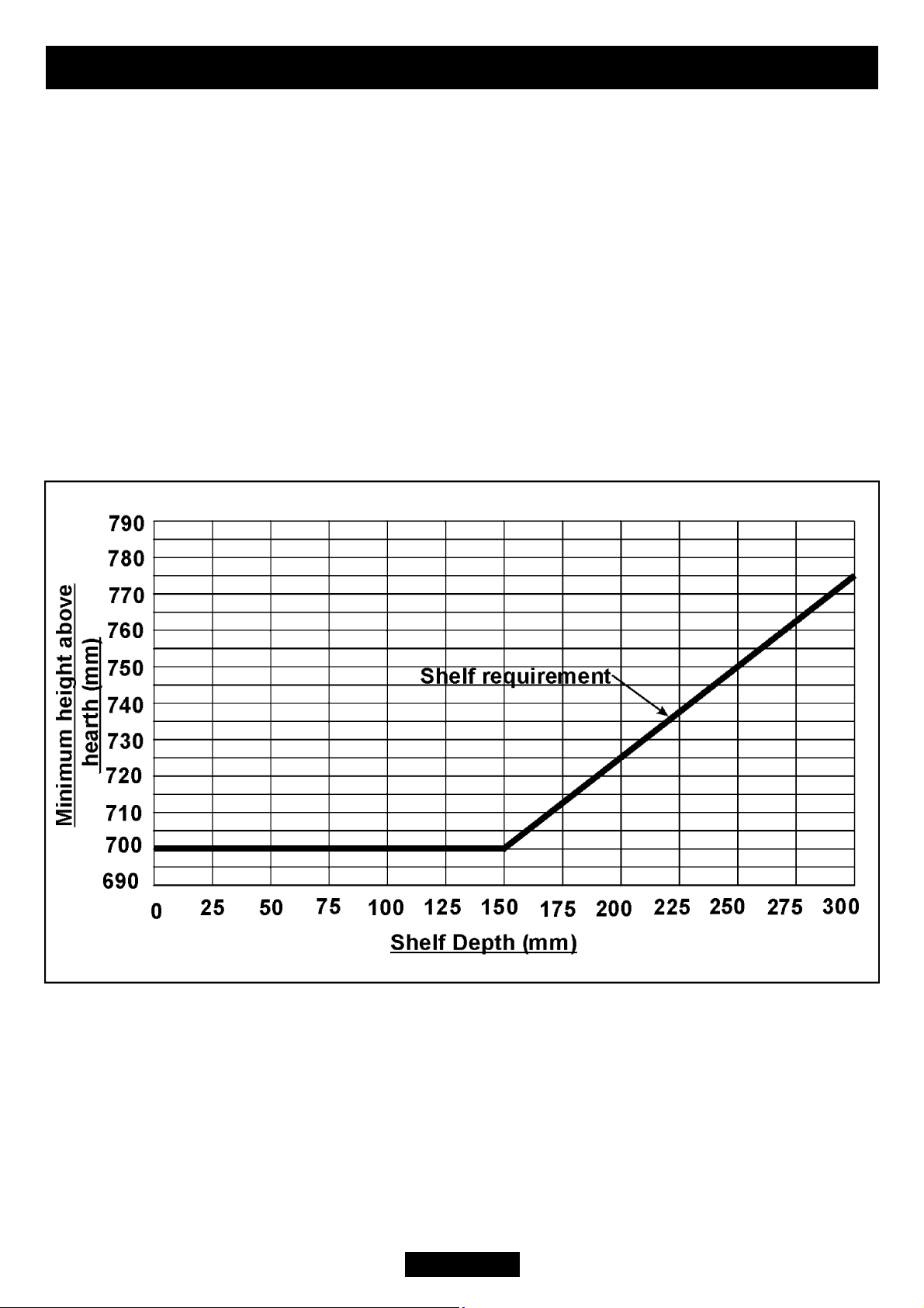
3.1.9 The minimum height from the top surface of the hearth to the underside of any
shelf made from wood or other combustible materials is detailed below.
! For a shelf up to 150mm deep: Minimum height = 700mm.
! For a shelf deeper than 150mm: 700mm + 12.5mm for every 25mm depth over
150mm. (See Graph 1)
Graph 1.
3.1.10Note that soft wall coverings (e.g. embossed vinyl, etc.) are easily affected by
bear this in mind when installing.
3.1.11
where steam is regularly present.
Page 8

An extractor fan may only be used in the same room as this appliance, or in any
performance of the appliance. Note the spillage test requirements detailed further on in
installed unless the fan is permanently disconnected, or provision is made to ensure that
requirements of this appliance. In GB reference should be made to BS 5871 Part 2 and
appliance closes down after a period of operation for no apparent reason, the consumer
should be informed to stop using the appliance until the installation and appliance have
been thoroughly checked. The A.S.D will shut the appliance down if an unacceptable
amount of harmful products of combustion accumulate. Under no circumstances should
the A.S.D be altered or bypassed in any way. Only a genuine manufacturers replacement
A fireguard complying with BS 8423 should be fitted for the protection of young
The minimum allowable distance from the outside of the appliance fascia to a
For access purposes a 50mm clearance is recommended from non-combustible surfaces.
INSTALLER GUIDE
3.1.12
area from which ventilation for the appliance is taken, if it does not affect the safe
this manual. If the fan is likely to affect the appliance, the appliance must not be
the fan and the appliance cannot be used at the same time.
A fan-powered flue system tends to depressurise the room containing the appliance.
3.1.13 Normal adventitious ventilation is usually sufficient to satisfy the ventilation
in IE reference should be made to the current edition of IS 813 “Domestic gas
Installations” which makes clear the conditions that must be met to demonstrate that
sufficient ventilation is available, however the spillage check (See further on in this
guide) may indicate a need for further ventilation in order to ensure that there is
adequate air replacement. If necessary seek expert advice.
3.1.14 The appliance is fitted with an A.S.D (Atmosphere sensing device). If the
part should be fitted. The individual A.S.D components are not replaceable.
3.1.15
children, the elderly, or the infirm.
3.1.16
corner wall having combustible material or any other combustible surface which
projects beyond the front of the appliance is 100mm.
Page 9
INSTALLER GUIDE
building fabric formed for the purpose of accommodating a built-in element such as a
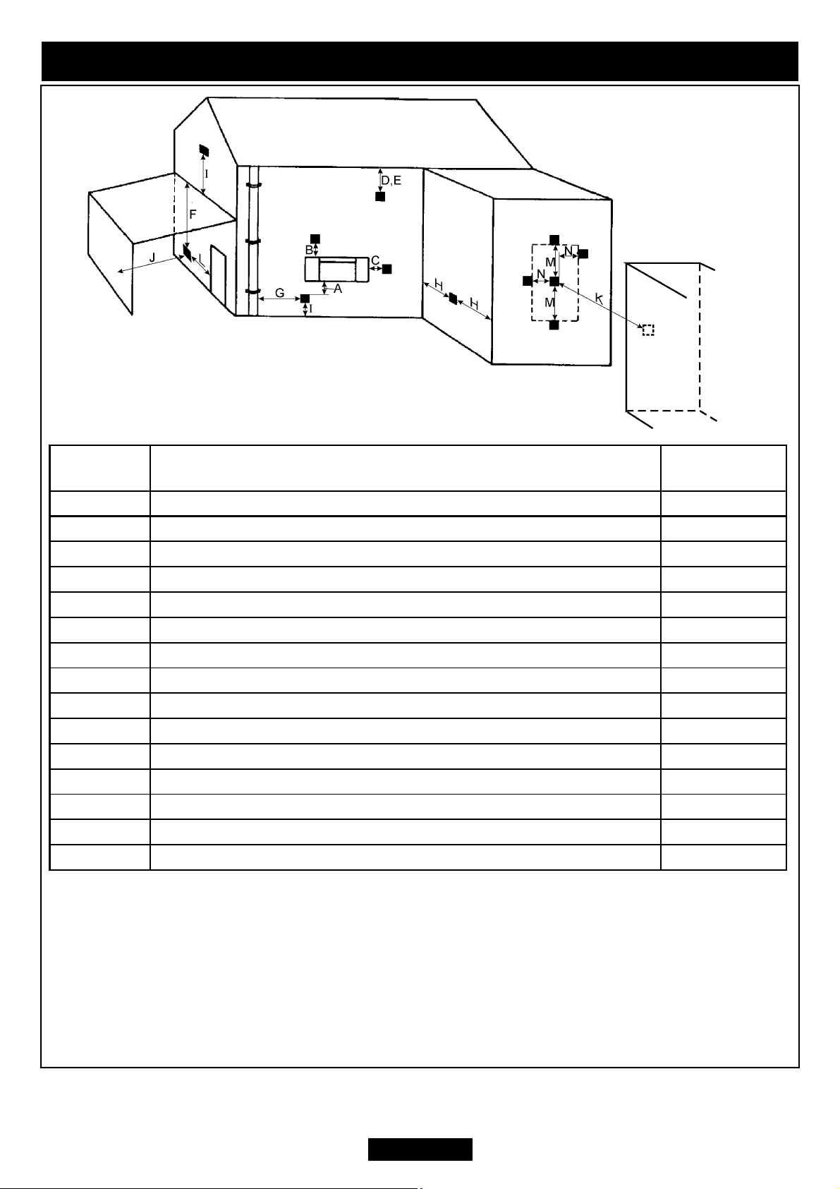
Minimum distances for terminal positions shown in the table are from slot openings.
Dimension
(See fig.2)
A* Directly below an opening, air brick, opening window etc. 300mm
B* Above an opening, air brick, opening window etc. 300mm
C* Horizontally to an opening, air brick, opening window etc. 300mm
D Below gutters, soil pipes or drain pipes 75mm
E Below eaves 200mm
F Below balconies or car port roof 200mm
G From a vertical drain pipe or soil pipe 150mm
H From an internal or external corner 200mm
I Above ground, roof or balcony level 300mm
J From a surface facing the terminal 600mm
K From a terminal facing the terminal 1200mm
L From an opening in a car port (e.g. door, window) into dwelling 1200mm
M Vertically from a terminal on the same wall 1500mm
N Horizontally from a terminal on the same wall 300mm
O Projection outward from wall 50mm
Terminal Position
Minimum
Distance
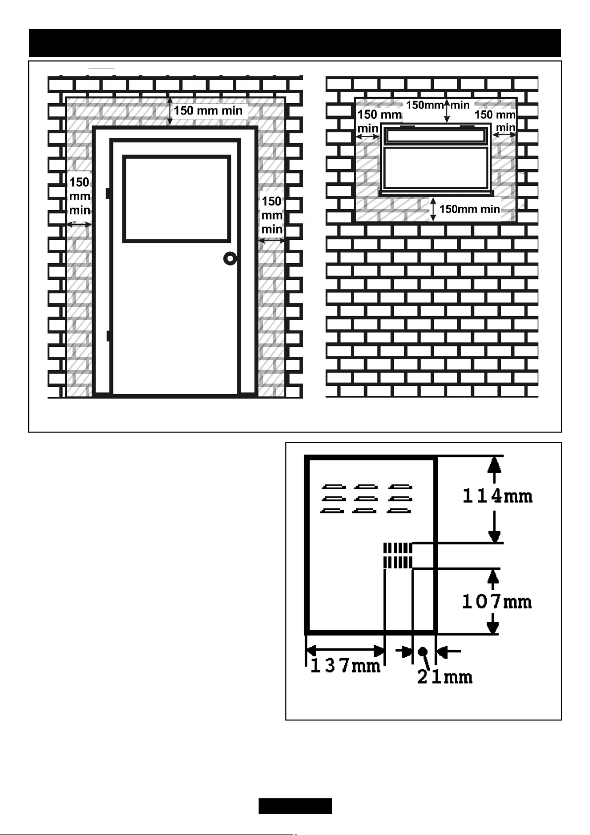
*In addition, the terminal should not be nearer than 150mm to an opening in the
window frame or door frame. See figure 3.
(See Figure 4)
Figure 2
Page 10
can come in contact with people near the building or be subject to damage. Even if the
regulations do not demand it, we recommend that the guard is fitted to prevent damage
INSTALLER GUIDE
Figure 3
3.2 Flue siting.
3.2.1 The flue terminal should be located
so that the wind can blow freely across it
at all times and where any blockage due
to leaves, snow, etc. is unlikely. The
minimum allowable distances from the
terminal are shown in figure 2.
Note: The distances are from the edge of
the vertical exit slots in the terminal not
from the edges of the rectangular box
(See figure 4).
3.2.2 This appliance is supplied with a
terminal guard. In England and Wales, the
Building Regulations require that the
terminal guard is fitted if the flue terminal
Figure 4
or blockage of the flue system by leaves etc.
Page 11
INSTALLER GUIDE
A concealed gas supply connection can be made through the rear panel.
Electrical connection is from the left side.
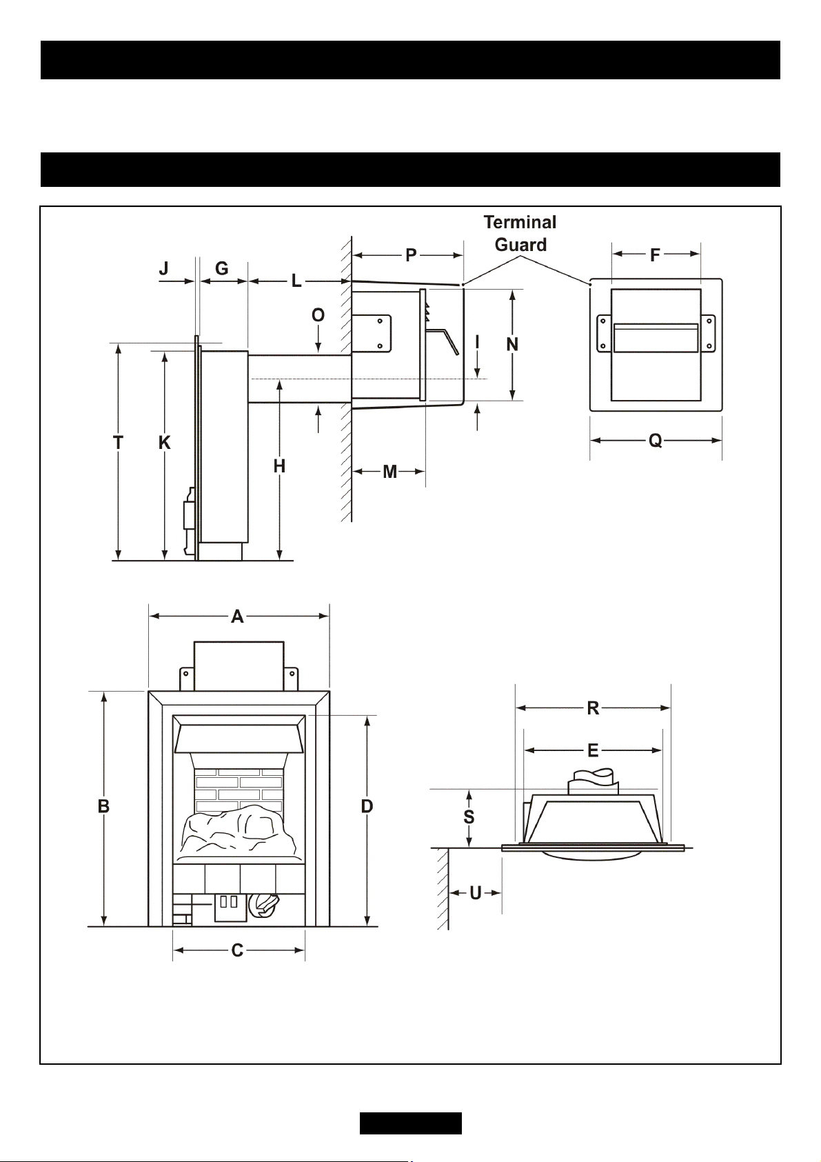
4. APPLIANCE DIMENSIONS
Figure 5. Appliance dimensions (Shown with fascia that is close fitted to the
outer flanges of the hotbox. Dimensions ‘A’ and ‘B’ may differ depending
upon the fascia fitted)
Page 12
 Loading...