

Page 1
EcoBlue Plus Combi
Installation and Service Manual
United Kingdom
en
Gas Fired Wall Mounted Condensing Combination Boiler
E
24 - 28 - 33
These instructions include the Benchmark Commissioning Checklist
and should be left with the user for safe keeping.
They must be read in conjunction with the Flue Installation Guide.
Page 2

Model Range
Baxi EcoBlue Plus 24 Combi
G.C.No 47-075-84
Baxi EcoBlue Plus 28 Combi
o
G.C.N
47-075-85
Baxi EcoBlue Plus 33 Combi
o
47-075-86
G.C.N
Building Regulations and the Benchmark Commissioning
Checklist
Building Regulations (England & Wales) require notification of the
installation of a heating appliance to the relevant Local Authority
Building Control Department. This can be achieved via a
Competent Persons Self Certification Scheme as an option to
notifying the Local Authority directly.
The Health & Safety Executive operates the ‘Gas Safe Register’, a self-
certification scheme for gas heating appliances.
This company is a member of the Benchmark initiative and fully
supports the aims of the programme. Its aim is to improve the
standards of installation and commissioning of central heating systems
in the UK and to encourage the regular servicing of all central heating
systems to ensure safety and efficiency.
Building Regulations require that installations should comply with
manufacturer's instructions. It is therefore important that the
commissioning checklist is completed by the installer. The relevant
section of Building Regulations only relates to dwellings. Therefore the
checklist only applies if the appliance is being installed in a dwelling or
some related structure.
0086
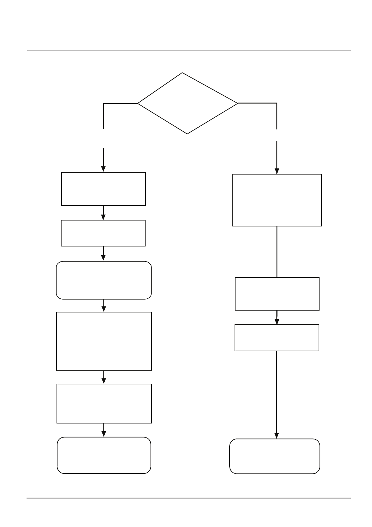
The flowchart opposite gives guidance for installers on the process
necessary to ensure compliance with Building Regulations.
The Benchmark Scheme
Benchmark places responsibilities on both manufacturers and installers.
The purpose is to ensure that customers are provided with the correct
equipment for their needs, that it is installed, commissioned and
serviced in accordance with the manufacturer’s instructions by
competent persons and that it meets the requirements of the
appropriate Building Regulations. The Benchmark Checklist can be
ISO 9001
FM 00866
© Baxi Heating UK Ltd 2014 All rights reserved. No part of this publication may be reproduced or transmitted in any form or by any means, or
stored in any retrieval system of any nature (including in any database), in each case whether electronic, mechanical, recording or otherwise,
without the prior written permission of the copyright owner, except for permitted fair dealing under Copyrights, Designs and Patents Act 1988.
Applications for the copyright owner’s permission to reproduce or make other use of any part of this publication should be made, giving details of
the proposed use, to the following address:
used to demonstrate compliance with Building Regulations and should
be provided to the customer for future reference.
Installers are required to carry out installation, commissioning and
servicing work in accordance with the Benchmark Code of Practice
which is available from the Heating and Hotwater Industry Council who
manage and promote the Scheme. Visit www.centralheating.co.uk for
more information.
The Company Secretary, Baxi Heating UK Limited, Brooks House, Coventry Road, Warwick. CV34 4LL
Full acknowledgement of author and source must be given.
WARNING: Any person who does any unauthorised act in relation to a copyright work may be liable to criminal prosecution and civil claims for
damages.
You have just purchased one of our appliances and we thank you for the trust you have placed in our products. Please note that
the product will provide good service for a longer period of time if it is regularly checked and maintained. Our customer support
network is at your disposal at all times.
2 EcoBlue Plus Combi 7212136 - 02 (08/14)
Page 3
Installer Notification Guidelines
Installer Notification Guidelines
Choose Building
Regulations Notification
Route
Competent Person's
Self Certification Scheme
Install and Commission this
appliance to manufacturer's
instructions
Complete the
Benchmark Checklist
If you notify via the ‘Gas Safe
Register’, the register will issue
the Building Regulations
certificate on members’ behalf
Building Control
Contact your relevant Local
Authority Building Control
(LABC) who will arrange
an inspection or contact
a government approved
inspector
Install and Commission this
appliance to manufacturer's
instructions
Scheme Members only
Call ‘Gas Safe Register’ on:
0800 408 5577
or log onto:
www.gassaferegister.co.uk
within 10 days
You must ensure that the
certificate number issued by
the ‘Gas Safe Register’ is written
onto the Benchmark Checklist
‘Gas Safe Register’ will issue a
Building Regulations Compliance
Certificate to the property owner
and inform the relevant LABC
Complete the
Benchmark Checklist
LABC will record the data
and will issue a
certificate of compliance
7212136 - 02 (08/14) EcoBlue Plus Combi 3
Page 4

Contents
Contents
1 Introduction
1.1 General
1.2 Additional Documentation
1.3 Symbols Used
1.4 Abbreviations
1.5 Extent of Liabilities
1.5.1 Manufacturer’s Liability
1.5.2 Installer’s Responsibility
1.6 Homologations
1.6.1 CE Marking
1.6.2 Standards
2 Safety
2.1 General Safety Instructions
2.2 Recommendations
2.3 Specific Safety Instructions
2.3.1 Handling
3 Technical Specifications
3.1 Technical Data
3.2 Dimensions and Connections
3.3 Electrical Diagram
4 Description of the Product
4.1 General Description
4.2 Operating Principle
4.2.1 Central Heating Mode
4.2.2 Domestic Hot Water Mode
4.2.3 Boiler Frost Protection Mode
4.2.4 Pump Protection
4.3 Main Components
4.4 Control Panel Description
4.5 Standard Delivery
4.6 Accessories & Options
4.6.1 Optional Extras
8
8
8
9
9
10
10
11
11
11
12
13
13
13
14
14
15
15
17
18
19
19
20
20
20
20
20
21
22
23
23
23
5 Before Installation
5.1 Installation Regulations
5.2 Installation Requirements
5.2.1 Gas Supply
5.2.2 Electrical Supply
5.2.3 Hard Water Areas
5.2.4 Bypass
5.2.5 System Control
5.2.6 Treatment of Water Circulating Systems
5.2.7 Showers
5.2.8 Expansion Vessel (CH only)
5.2.9 Safety Pressure Relief Valve
5.3 Choice of the Location
5.3.1 Location of the Appliance
5.3.2 Data Plate
5.3.3 Bath & Shower Rooms
5.3.4 Ventilation
5.3.5 Condensate Drain
5.3.6 Clearances
5.3.7 Flue/Chimney Location
5.3.8 Horizontal Flue/Chimney Systems
4 EcoBlue Plus Combi 7212136 - 02 (08/14)
24
24
25
25
25
25
25
25
26
26
26
27
28
28
28
28
28
29
31
32
34
Page 5

Contents
Contents
5.3.9 Flue/Chimney Lengths
5.3.10 Flue/Chimney Trim
5.3.11 Terminal Guard
5.3.12 Flue/Chimney Deflector
5.3.13 Flue/Chimney Accessories
5.4 Transport
5.5 Unpacking & Initial Preparation
5.5.1 Unpacking
5.5.2 Initial Preparation
5.5.3 Flushing
5.6 Connecting Diagrams
5.6.1 System Filling and Pressurising
5.6.2 Domestic Hot Water Circuit
6 Installation
6.1 General
6.2 Assembly
6.2.1 Fitting the Pressure Relief Discharge Pipe
6.2.2 Connecting the Condensate Drain
6.3 Preparation
6.3.1 Panel Removal
6.4 Air Supply / Flue Gas Connections
6.4.1 Connecting the Flue/Chimney
6.5 Electrical Connections
6.5.1 Electrical Connections of the Appliance
6.5.2 Connecting External Devices
6.6 Filling the Installation
6.7 External Controls
6.7.1 Installation of External Sensors
6.7.2 Optional Outdoor Sensor
35
35
35
35
35
35
36
36
36
36
37
37
37
38
38
38
38
39
39
39
40
40
42
42
42
42
43
43
43
7 Commissioning
7.1 General
7.2 Checklist before Commissioning
7.2.1 Preliminary Electrical Checks
7.2.2 Checks
7.3 Commissioning Procedure
7.3.1 De-Aeration Function
7.4 Gas Settings
7.4.1 Check Combustion - ‘Chimney Sweep’ Mode
7.5 Configuring the System
7.5.1 Check the Operational (Working Gas Inlet Pressure & Gas Rate)
7.6 Final Instructions
7.6.1 Handover
7.6.2 System Draining
8 Operation
8.1 General
8.2 To Start-Up
8.3 To Shutdown
8.4 Use of the Control Panel
8.5 Frost Protection
9 Settings
9.1 Parameters
44
44
44
44
44
45
45
45
45
47
47
47
47
48
49
49
49
49
50
50
51
51
7212136 - 02 (08/14) EcoBlue Plus Combi 5
Page 6

Contents
10 Maintenance
10.1 General & Service Message
10.2 Standard Inspection & Maintenance Operation
10.3 Specific Maintenance Operations Changing Components
10.3.1 Spark Ignition & Flame Sensing Electrodes
10.3.2 Fan
10.3.3 Air / Gas Venturi
10.3.4 Burner
10.3.5 Insulation
10.3.6 Flue Sensor
10.3.7 Igniter
10.3.8 Heating Flow & Return Sensors
10.3.9 Safety Thermostat
10.3.10 DHW NTC Sensor
10.3.11 Pump - Head Only
10.3.12 Pump - Complete
10.3.13 Automatic Air Vent
10.3.14 Safety Pressure Relief Valve
10.3.15 Heating Pressure Gauge
10.3.16 Plate Heat Exchanger
10.3.17 Hydraulic Pressure Sensor
10.3.18 DHW Flow Regulator & Filter
10.3.19 DHW Flow Sensor (‘Hall Effect’ Sensor)
10.3.20 Diverter Valve Motor
10.3.21 Main P.C.B.
10.3.22 Boiler Control P.C.B.
10.3.23 Expansion Vessel
10.3.24 Gas Valve
10.3.25 Setting the Gas Valve (CO
Check)
2
52
52
53
54
54
55
55
56
56
57
57
57
57
57
58
58
58
59
59
60
60
61
61
61
62
62
63
63
64
11 Troubleshooting
11.1 Error Codes
11.2 Fault Finding
12 Decommissioning Procedure
12.1 Decommissioning Procedure
13 Spare Parts
13.1 General
13.2 Spare Parts List
14 Notes
15 Benchmark Commissioning Checklist
65
65
65
71
71
72
72
72
73
74
6 EcoBlue Plus Combi 7212136 - 02 (08/14)
Page 7

7212136 - 02 (08/14) EcoBlue Plus Combi 7
Page 8
1 Introduction
1 Introduction
1.1 General
WARNING
Installation, repair and maintenance must only be
carried out only by a competent person. This
document is intended for use by competent persons.
All Gas Safe registered engineers carry an ID card with their
licence number and a photograph. You can check your engineer
is registered by telephoning 0800 408 5500 or online at
www.gassaferegister.co.uk
This appliance must be installed in accordance with the
manufacturer’s instructions and the regulations in force. If the
appliance is sold or transferred, or if the owner moves leaving
the appliance behind you should ensure that the manual is kept
with the appliance for consultation by the new owner and their
installer. Read the instructions fully before installing or using the
appliance.
In GB, this must be carried out by a competent person as stated
in the Gas Safety (Installation & Use) Regulations (as may be
amended from time to time).
Definition of competence: A person who works for a Gas Safe
registered company and holding current certificates in the
relevant ACS modules, is deemed competent.
In IE, this must be carried out by a competent person as stated
in I.S. 813 “Domestic Gas Installations”.
The addition of anything that may interfere with the normal
operation of the appliance without express written permission
from the manufacturer or his agent could invalidate the
appliance warranty. In GB this could also infringe the Gas Safety
(Installation and Use) Regulations.
The appliance is designed as a boiler for use in residential
domestic environments on a governed meter supply only. The
selection of this boiler is entirely at the owner’s risk. If the
appliance is used for purposes other than or in excess of these
specifications, the manufacturer will not accept any liability for
resulting loss, damage or injury.
The manufacturer will not accept any liability whatsoever
for loss, damage or injury arising as a result of failure to
observe the instructions for use, maintenance and
installation of the appliance.
WARNING
Check the information on the data plate is
compatible with local supply conditions.
1.2 Additional Documentation
These Installation & Service Instructions must be read in
conjunction with the Flue Installation Guide supplied in the
Literature Pack.
Various timers, external controls, etc. are available as optional
extras. Full details are contained in the relevant sales literature.
8 EcoBlue Plus Combi 7212136 - 02 (08/14)
Page 9
Introduction 1
1.3 Symbols Used
In these instructions, various levels are employed to draw the
user's attention to particular information. In so doing, we wish to
safeguard the user's safety, prevent hazards and guarantee
correct operation of the appliance. Each level is accompanied by
a warning triangle
DANGER
Risk of a dangerous situation causing serious
physical injury.
WARNING
Risk of a dangerous situation causing slight physical
injury.
CAUTION
Risk of material damage.
Signals important information .
Signals a referral to other instructions or other pages
in the instructions.
1.4 Abbreviations
DHW: Domestic hot water
CH: Central heating
GB: Great Britain
IE: Ireland
BS: British standard
HHIC: Heating and Hotwater Industry Council
7212136 - 02 (08/14) EcoBlue Plus Combi 9
Page 10

1 Introduction
1.5 Extent of Liabilities
1.5.1 Manufacturer's Liability
Our products are manufactured in compliance with the
requirements of the various european applicable Directives.
They are therefore delivered with marking and all relevant
documentation. In the interest of customers, we are
continuously endeavouring to make improvements in product
quality. All the specifications stated in this document are
therefore subject to change without notice.
The manufacturer will not accept any liability for loss, damage or
injury arising as a result of:-
Failure to abide by the instructions on using the appliance.
Failure to regularly maintain the appliance, or faulty or
inadequate maintenance of the appliance.
Failure to abide by the instructions on installing the
appliance.
This company declares that no substances harmful to
health are contained in the appliance or used during
appliance manufacture.
The appliance is suitable only for installation in GB and IE and
should be installed in accordance with the rules in force, and
only used in a suitably ventilated location.
In GB, the installation must be carried out by a Gas Safe
Registered Installer. It must be carried out in accordance with
the current and relevant requirements of legislation and
guidance including the:-
• Gas Safety (Installation & Use) Regulations.
• The appropriate Building Regulations either The
Building Regulations, The Building Regulations
(Scotland), Building Regulations (Northern Ireland).
• The Water Fittings Regulations or Water Byelaws in
Scotland.
• The Current I.E.E. Wiring Regulations.
Where no specific instructions are given, reference should be
made to the relevant British Standard Code of Practice.
In IE, the installation must be carried out by a competent Person
and installed in accordance with the current edition of I.S. 813
‘Domestic Gas Installations’, the current Building Regulations
and reference should be made to the current ETCI rules for
electrical installation.
Prior to commissioning all systems must be thoroughly
flushed and treated with inhibitor (see section 5.2.6). Failure
to do so will invalidate the appliance warranty.
Incorrect installation could invalidate the warranty and may lead
to prosecution.
10 EcoBlue Plus Combi 7212136 - 02 (08/14)
Page 11

Introduction 1
1.5.2 Installer's Responsibility
The installer is responsible for the installation and initial start up
of the appliance. The installer must adhere to the following
instructions:
Read and follow the instructions given in the manuals
provided with the appliance.
Carry out installation in compliance with the prevailing
legislation and standards.
Ensure the system is flushed and inhibitor added.
Install the flue/chimney system correctly ensuring it is
operational and complies with prevailing legislation and
standards, regardless of location of the boiler’s installation.
Only the installer should perform the initial start up and carry
out any checks necessary.
Explain the installation to the user.
Complete the Benchmark Commissioning Checklist - this is a
condition of the warranty !
Warn the user of the obligation to check the appliance and
maintain it in good working order.
Give all the instruction manuals to the user.
1.6 Homologations
1.6.1 CE Marking
EC - Declaration of Conformity
Baxi Heating UK Limited being the manufacturer / distributor
within the European Economic Area of the following
Baxi EcoBlue Plus 24 - 28 - 33 Combi
declare that the above is in conformity with the provisions of the
Council Directive
2009/142/EC 92/42/EEC 2004/108/EC 2006/95/EC
and has been subject to the following conformity procedures laid
down in
Annex 2 - Article 3 of 2009/142/EC
under the supervision of the British Standards Institution, a
Notified Body authorized by the United Kingdom Competent
Authority, and carrying the Notified Body Number 0086.
Type test for purpose of Regulation 5 certified by:
Notified Body 0085.
Product/Production certified by:
Notified Body 0086.
For GB/IE only.
7212136 - 02 (08/14) EcoBlue Plus Combi 11
Page 12

1 Introduction
1.6.2 Standards
Codes of Practice - refer to the most recent version
In GB the following Codes of Practice apply:
Standard Scope
BS 6891 Gas Installation.
BS 5546 Installation of hot water supplies for domestic
purposes.
BS EN 12828 Heating systems in buildings.
BS EN 12831 Heating systems in buildings - Calculation of
load.
BS EN 14336 Installation & commissioning of water based
heating systems.
BS 6798 Installation of gas fired hot water boilers.
BS 5440 Part 1 Flues.
BS 5440 Part 2 Ventilation.
BS 7074 Expansion vessels and ancillary equipment for
sealed water systems.
BS 7593 Treatment of water in domestic hot water
central heating systems.
BS 4814 Specification for Expansion Vessels using an
internal diaphragm, for sealed hot water
systems.
IGE/UP/7/1998 Guide for gas installations in timber framed
housing.
In IE the following Codes of Practice apply:
Standard Scope
I.S. 813 Domestic Gas Installations.
The following standards give valuable additional information;
BS 5546 Installation of hot water supplies for domestic
purposes.
BS EN 12828 Heating systems in buildings.
BS EN 12831 Heating systems in buildings - Calculation of
load.
BS EN 14336 Installation & commissioning of water based
heating systems.
BS 7074 Expansion vessels and ancillary equipment for
sealed water systems.
BS 7593 Treatment of water in domestic hot water
central heating systems.
12 EcoBlue Plus Combi 7212136 - 02 (08/14)
Page 13
2 Safety
Safety 2
2.1 General Safety Instructions
DANGER
If you smell gas:
1. Turn off the gas supply at the meter
2. Open windows and doors in the hazardous area
3. Do not operate light switches
4. Do not operate any electrical equipment
5. Do not use a telephone in the hazardous area
6. Extinguish any naked flame and do not smoke
7. Warn any other occupants and vacate the
premises
8. Telephone the National Gas Emergency Service
on:- 0800 111 999
2.2 Recommendations
WARNING
Installation, repair and maintenance must be carried
out by a Gas Safe Registered Engineer
(in accordance with prevailing local and national
regulations).
When working on the boiler, always disconnect the
boiler from the mains and close the main gas inlet
valve.
After maintenance or repair work, check the
installation to ensure that there are no leaks.
CAUTION
The boiler should be protected from frost.
Only remove the casing for maintenance and repair
operations. Replace the casing after maintenance
and repair operations.
7212136 - 02 (08/14) EcoBlue Plus Combi 13
Page 14

2 Safety
2.3 Specific Safety Instructions
2.3.1 Handling
General
• The following advice should be adhered to, from when first
handling the boiler to the final stages of installation, and
also during maintenance.
• Most injuries as a result of inappropriate handling and lifting
are to the back, but all other parts of the body are
vulnerable, particularly shoulders, arms and hands. Health
& Safety is the responsibility of EVERYONE.
• There is no ‘safe’ limit for one man - each person has
different capabilities. The boiler should be handled and lifted
by TWO PEOPLE.
• Do not handle or lift unless you feel physically able.
• Wear appropriate Personal Protection Equipment
e.g. protective gloves, safety footwear etc.
Preparation
• Co-ordinate movements - know where, and when, you are
both going.
• Minimise the number of times needed to move the boiler plan ahead.
• Always ensure when handling or lifting the route is clear
and unobstructed. If possible avoid steps, wet or slippery
surfaces, unlit areas etc. and take special care on
ladders/into lofts.
Technique
• When handling or lifting always use safe techniques - keep
your back straight, bend your knees. Don’t twist - move your
feet, avoid bending forwards and sideways and keep the
load as close to your body as possible.
• Where possible transport the boiler using a sack truck or
other suitable trolley.
• Always grip the boiler firmly, and before lifting feel where the
weight is concentrated to establish the centre of gravity,
repositioning yourself as necessary. See the ‘Installation’
section of these instructions for recommended lift points.
Remember
• The circumstances of each installation are different. Always
assess the risks associated with handling and lifting
according to the individual conditions.
• If at any time when installing the boiler you feel that you
may have injured yourself STOP !! DO NOT ‘work through’
the pain - you may cause further injury.
IF IN ANY DOUBT DO NOT HANDLE OR LIFT THE BOILER OBTAIN ADVICE OR ASSISTANCE BEFORE PROCEEDING !
14 EcoBlue Plus Combi 7212136 - 02 (08/14)
Page 15
3 Technical Specifications
Technical Specifications 3
3.1 Technical Data
Appliance Type C
13 C33 C53
Appliance Category CAT I
2H
Heat Input CH (Net)
Max Min
24 model kW 20 4.7
28 model kW 24 5.7
33 model kW 28 6.8
Heat Output CH (Non-Condensing)
Max Min
24 model kW 20 4.6
28 model kW 24 5.5
33 model kW 28 6.6
Heat Output CH (Condensing)
Max Min
24 model kW 21.2 4.9
28 model kW 25.3 6.0
33 model kW 29.6 7.1
Heat Input DHW (Net)
Max
24 model kW 24.7
28 model kW 28.9
33 model kW 34
Heat Output DHW
Max
24 model kW 24
28 model kW 28
33 model kW 33
Gas Nozzle Injector
24 model mm Ø 5.0
28 model mm Ø 5.6
33 model mm Ø 6.6
NOxClass 5
NOTE: All data in this section are nominal
values and subject to normal production
tolerances.
Electrical Supply 230V~ 50Hz
(Appliance must be connected to an
earthed supply)
Power Consumption
24 model W 123
28 model W 132
33 model W 135
Electrical Protection
IPX5D (without integral timer)
IP20 (with integral timer)
External Fuse Rating 3A
Internal Fuse Rating F2L
Condensate Drain
To accept 21.5mm (3/4in) plastic waste pipe
Flue Terminal Diameter 100mm
Dimensions Projection 125mm
Connections copper tails
Gas Inlet - 22mm
Heating Flow - 22mm
Heating Return - 22mm
Cold Water Inlet - 15mm
Hot Water Outlet - 15mm
Pressure Relief Discharge - 15mm
Outercase Dimensions
Casing Height - 700mm
Overall Height Inc Flue Elbow - 860mm
Casing Width - 390mm
Casing Depth - 295mm
Clearances
Above Casing 175 mm Min
Below Casing 150 mm* Min
Front 450 mm Min (For Servicing)
Front 5 mm Min (In Operation)
L.H. Side 5 mm Min
R.H. Side 5 mm Min
*This is MINIMUM recommended dimension.
Greater clearance will aid installation and
maintenance.
Weights
(24 model)
Packaged Boiler Carton 39.2kg
Installation Lift Weight 34kg
(28 model)
Packaged Boiler Carton 39.2kg
Installation Lift Weight 34kg
(33 model)
Packaged Boiler Carton 41.2kg
Installation Lift Weight 36kg
Central Heating Primary Circuit
Pressures
bar
Safety Discharge 3
Max Operating 2.5
Min Operating 0.5
Recommended Operating Range 1-2
DHW Circuit bar
Pressures
Max Operating 8
Min Operating 0.15
Flow Rates (24) (28) (33)
l/min l/min l/min
DHW Flow Rate
@ 30o C Rise 10.9 12.9 15.3
DHW Flow Rate
@ 35o C Rise 9.8 11.5 13.5
IMPORTANT
Min Working
DHW Flow Rate 2 2 2
Where Low Flow Taps or Fittings are intended to
be used in the DHW system connected to a Baxi
EcoBlue Combi it is strongly recommended that
the DHW flow rate DOES NOT fall below 2.5
l/min. This will ensure reliable operation of the
DHW function.
Expansion Vessel - (For Central Heating
only. Integral with appliance)
bar
Min Pre-charge Pressure 1.0
litre
Max Capacity of
CH System 100
Primary Water Content
of Boiler (unpressurised) 2.5
Temperatures
C.H. Flow Temp (adjustable)
25°C to 80°C max (± 5°C)
D.H.W. Flow Temp (adjustable)
40°C to 60°C max (± 5°C)
dependent upon flow rate
7212136 - 02 (08/14) EcoBlue Plus Combi 15
Page 16
3 Technical Specifications
3.1 Technical Data (cont)
Pump
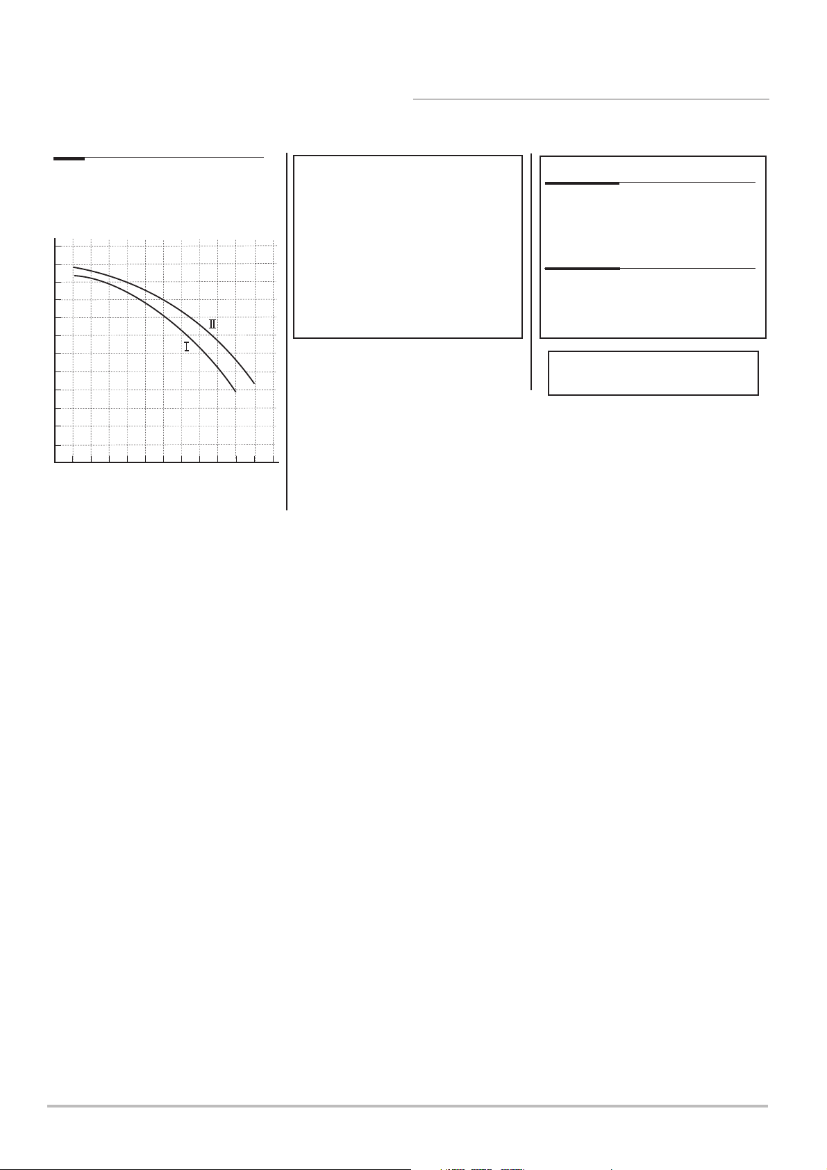
Available Head See graph below
Pump - Available Head
6
5.5
5
4.5
4
3.5
3
2.5
2
Metre (wg)
1.5
1
0.5
0
200 400 600 800 1000 1200
0
Flow Rate (l/h)
SEDBUK Declaration
SAP 2005 Seasonal Efficiency is
91.1%
SAP 2009 Annual Efficiency is
89%
This value is used in the UK Government’s
Standard Assessment Procedure (SAP) for energy
rating of dwellings. The test data from which it has
been calculated has been certified by 0085.
NATURAL GAS ONLY !
Max Gas Rate (Natural Gas - G20)
(After 10 mins)
24 model m3/h 2.61
28 model m3/h 3.05
33 model m3/h 3.59
Dynamic (nominal) Inlet Pressure
(Natural Gas - G20)
mbar 20
with a CV of 37.78 MJ/m
NOTE: All data in this section are nominal
values and subject to normal production
tolerances.
3
16 EcoBlue Plus Combi 7212136 - 02 (08/14)
Page 17
Pressure
Relief
Valve
(15mm)
Condensate
Drain
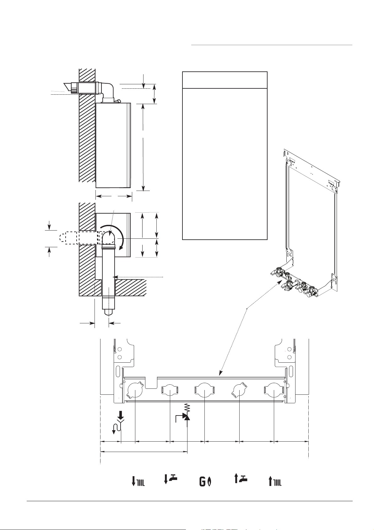
38.5mm
26.5
mm
65 mm 65 m m 65 mm 65 m m 65 mm
162.5mm (PRV)
Hot Water
Outlet
(15mm)
Cold Water
Inlet
(15mm)
Heating
Return
(22mm)
Heating
Flow
(22mm)
Gas
Inlet
(22mm)
There must be no part of the air duct
(white tube) visible outside the property.
Technical Specifications 3
3.2 Dimensions and Connections
Dimensions
At least 1.5°
E
G
A 700mm
B 295mm
C 390mm
A
D 116mm Ø Min.
E 160mm
(207mm for 80/125mm
flue systems)
F 130mm
B
360° Orientation
G 106mm
H 228mm
H
J 162mm
D
C
J
Flue Ø 100mm
Tap Rail
F
7212136 - 02 (08/14) EcoBlue Plus Combi 17
Page 18
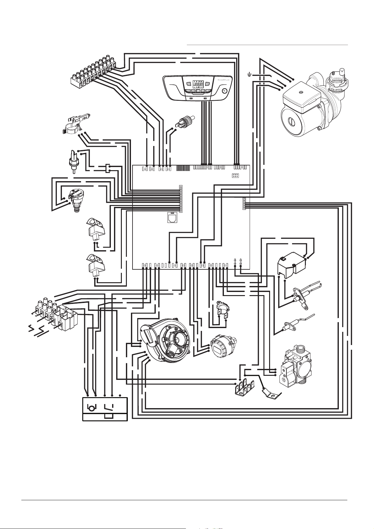
3 Technical Specifications
M2
Low Voltage
External Control
Connection
6
7
8
9
10
3.3 Electrical Diagram
1
2
3
4
5
w
Boiler
br
Controls
r
bk
R
/P
++
/R
g/y
Sensor
M1
Mains Voltage
Connection
1
2
Link
y
g/y
b
E
N
br
L
Mains Input Cable
Hall Effect
Sensor
Flue
bk
Heating
Return
Sensor
Heating
Flow
Sensor
b
b
r
g
Hydraulic
Pressure
Switch
br
b
bk
X42X41X40
X23X22
br
bk
Diverter
Valve
Motor
b
g
g/y
b
br
bk
gr
br
Pump
b
Igniter
Spark
Ignition
Electrode
Flame
Sensing
Electrode
g/y
b
br
g
bk
b
w
r
b
b
r
r
g/y
b
g/y
g/y
p
y
X20 X21 X30
X50
X10 X11 X12 X13 X14
br
bk
b
br
g
g
Fan
DHW
NTC
Sensor
g
X60
X1 X2
b
bk
b
b
r
w
bk
Safety
Thermostat
Gas
Valve
Timer Connector
1
2345
b
br
Timer Bridge
Key To Wiring Colours
b - Blue
r - Red
bk - Black
br - Brown
w - White
gr - Grey
18 EcoBlue Plus Combi 7212136 - 02 (08/14)
g - Green
g/y - Green/Yellow
y - Yellow
p - Purple
Page 19
4 Description of the Product
Information
Label
Description of the Product 4
4.1 General Description
1. The Baxi EcoBlue Plus Combi boilers are fully automatic gas
fired wall mounted condensing combination boilers. They are
room sealed and fan assisted, and will serve central heating and
mains fed domestic hot water.
2. The boiler is set to give a maximum output of :-
24 model - 24 kW DHW
21.2 kW CH (Condensing)
28 model - 28 kW DHW
25.3 kW CH (Condensing)
33 model - 33 kW DHW
29.6 kW CH (Condensing)
3. The boiler is factory set for use on Natural Gas (G20).
4. The boiler is suitable for use only on fully pumped sealed
heating systems. Priority is given to domestic hot water.
Boiler Control
Flap
Fig. 1
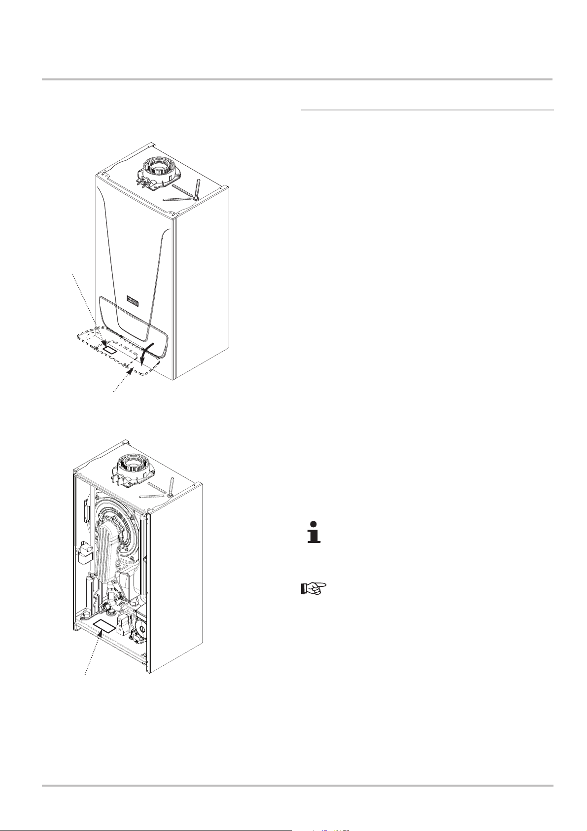
5. The boiler data badge gives details of the model, serial
number and Gas Council number and is situated on the boiler
lower panel. It is visible when the control box is lowered (Fig. 2).
6. The boiler model, serial number and Gas Council number are
also shown on the information label behind the boiler control flap
(Fig. 1). This is for user reference.
7. The boiler is intended to be installed in residential/domestic
environments on a governed meter supply only.
8. The boiler must be installed with one of the purpose designed
flues such as one of the standard horizontal telescopic flue kits
detailed in the Flue Installation Guide .
All systems must be thoroughly cleansed, flushed and
treated with inhibitor (see section 5.2.6).
These Installation & Servicing Instructions MUST be
read in conjunction with the Flue Installation Guide supplied in
the Literature Pack.
Data Badge
Fig. 2
Control Box
removed for clarity
7212136 - 02 (08/14) EcoBlue Plus Combi 19
Page 20
4 Description of the Product
19
20
15
13
7
D
14
18
26
17
16
8
12
10
11
A
BC
9
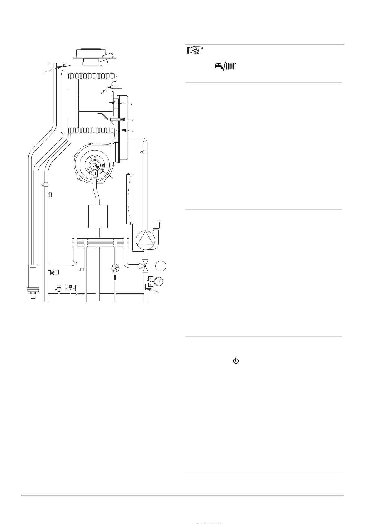
Boiler Schematic
Layout
Key
1. Pump with Automatic Air Vent
2. Diverter Valve Assembly
3. Diverter Valve motor
4. CH System Pressure Gauge
5. Central Heating Filter
6. Domestic Hot Water Filter
7. Domestic Hot Water Priority Sensor
(‘Hall Effect’ Sensor)
8. Domestic Hot Water NTC sensor
9. Non-return Valve
10. Hydraulic Pressure Sensor
11. Boiler Drain Tap
12. Safety Pressure Relief Valve
13. Plate Heat Exchanger
Connections:A – Condensate Drain
B – Heating Flow
C – Domestic Hot Water Outlet
D – Gas Inlet
E – Cold Water Inlet On/Off Valve and filter
F – Heating Return
14. Condensate Trap
15. Gas Valve
16. Safety Thermostat (105°C)
17. Heating Flow Sensor
18. Flue Sensor
19. Boiler Adaptor
20. Primary Heat Exchanger
21. Spark Ignition Electrode
22. Burner
23. Flame Sensing Electrode
24. Air/Gas Collector
25. Return Heating Sensor
26. Fan
27. Air/Gas Venturi
28. Expansion Vessel
27
E
4.2 Operating Principle
The boiler can be set in 3 operating modes:- ‘Summer’
(DHW only), ‘Winter’ (CH & DHW) or ‘Heating Only’ (CH only) by
use of the button.
4.2.1 Central Heating Mode
21
22
23
24
25
28
1
2
M
6
F
4
5
1. With a demand for heating, the pump circulates water through
the primary circuit.
2. Once the burner ignites the fan speed controls the gas rate to
maintain the heating temperature measured by the temperature
sensor.
3. When the flow temperature exceeds the setting temperature,
a 3 minute delay occurs before the burner relights automatically
(anti-cycling). The pump continues to run during this period.
4. When the demand is satisfied the burner is extinguished and
the pump continues to run for a period of 3 minutes (pump
overrun).
4.2.2 Domestic Hot Water Mode
1. Priority is given to the domestic hot water supply. A demand
at a tap or shower will override any central heating requirement.
2. The flow of water will operate the DHW Sensor (Hall Effect
Sensor) which requests the 3 way valve to change position. This
will allow the pump to circulate the primary water through the
3
DHW plate heat exchanger.
3. The burner will light automatically and the temperature of the
domestic hot water is controlled by the temperature sensor.
4. When the domestic hot water demand ceases the burner will
extinguish and the diverter valve will remain in the domestic hot
water mode, unless there is a demand for central heating.
4.2.3 Boiler Frost Protection Mode
1. The frost protection mode is integral to the appliance and
functions as long as there is power to the boiler, as indicated by
the standby signal .
2. With CH & DHW or CH only selected, when the boiler
temperature falls below 5°C the boiler will fire until a
temperature of 30°C is reached.
3. If DHW only is selected, when the boiler CH temperature falls
below 5°C the boiler will fire until a temperature of 30°C is
reached. When the boiler DHW temperature falls below 5°C the
boiler will fire until a temperature of 7°C is reached.
4. Further protection can be incorporated by using a system
frost thermostat.
4.2.4 Pump Protection
1. This activates once a week if there has been no demand. The
pump runs for 30 seconds to prevent sticking.
20 EcoBlue Plus Combi 7212136 - 02 (08/14)
Page 21
EV1
EV2
P. OUT
1 2 3 4
VENT
ADJ.
Description of the Product 4
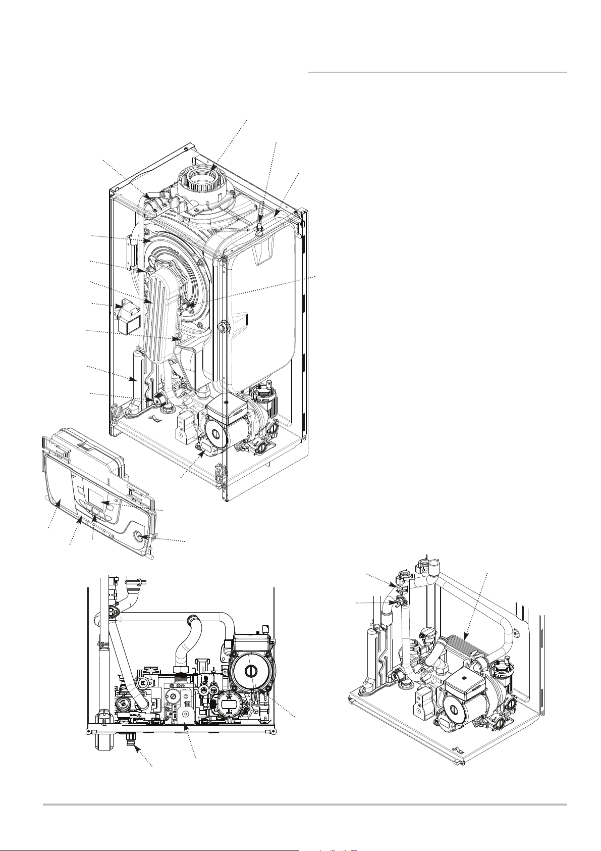
4.3 Main Components
2
14
11
10
23
7
15
12
8
1. Expansion Vessel
2. Boiler Adaptor
3
1
3. Primary Heat Exchanger
4. Plate Heat Exchanger
5. Pump with Automatic Air Vent
6. Central Heating System Pressure Gauge
7. Fan Assembly with Venturi
8. Expansion Vessel Locating Stud
9. Flame Sensing Electrode
9
10. Air/Gas Collector
11. Spark Ignition Electrode
12. Combustion Box Cover & Burner
13. Control Box Display
14. Condensate Trap
15. Safety Pressure Relief Valve
16. Gas Valve
17. Diverter Valve Motor
18. Boiler Controls
19. Boiler Control Box
20. Boiler Drain Tap
21. Heating Flow Sensor
22. Safety Thermostat
17
23. Igniter
24. Access Panel for Timer Connector
13
24
19
18
6
21
4
22
RQRQADJ.
P. OUT
VENT
EV2
1 2 3 4
EV1
5
20
16
7212136 - 02 (08/14) EcoBlue Plus Combi
21
Page 22
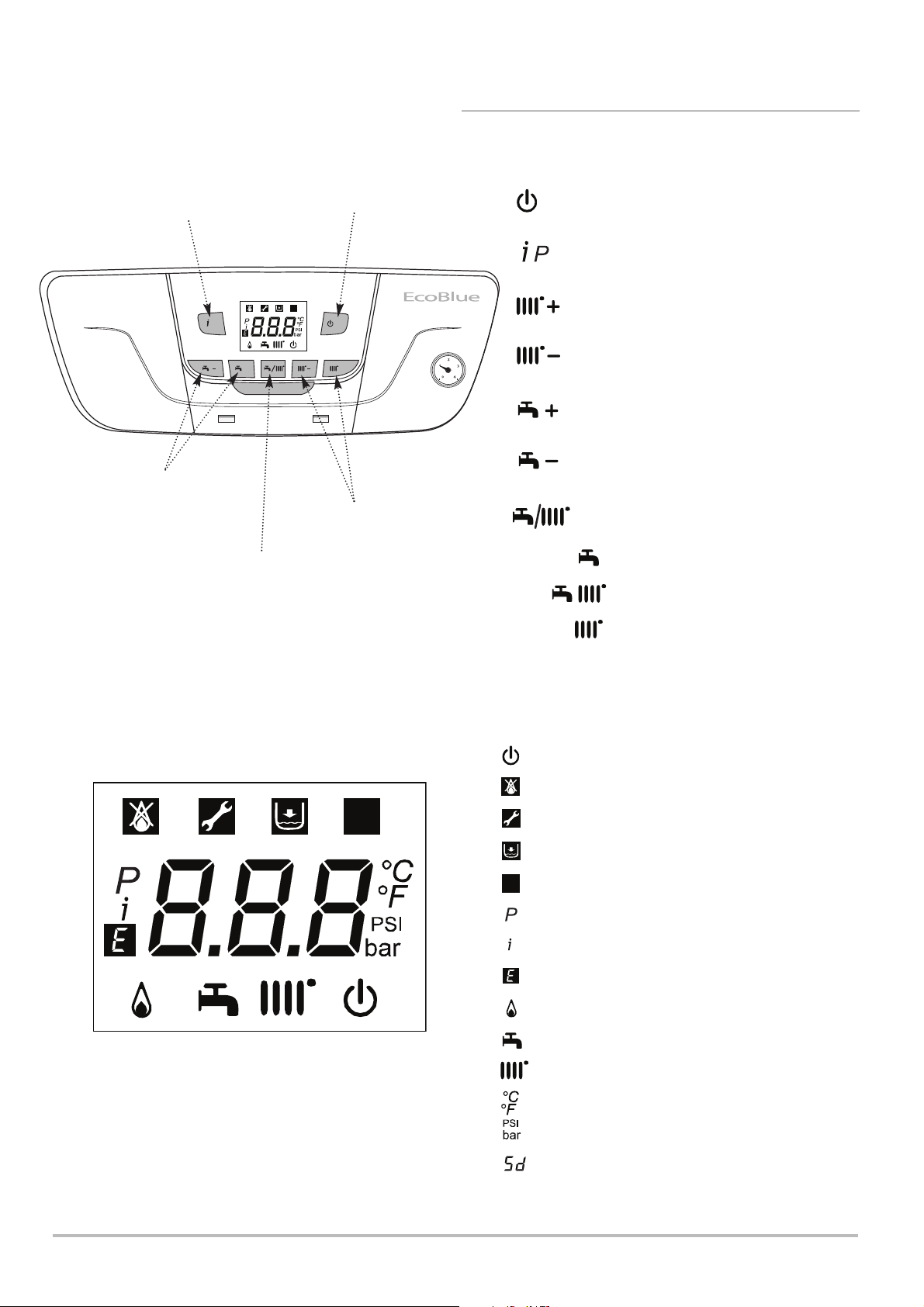
4 Description of the Product
R
4.4 Control Panel Description
Key to Controls
Boiler Information View
Domestic Hot Water (DHW)
Temperature Adjustment
Summer - Winter - Heating Only
Standby - Reset - Esc
/P
++
R
/R
Central Heating (CH)
Temperature Adjustment
Mode
Standby - Reset - Esc Button
R
Boiler Information View Button
Increase CH Temperature Button
Decrease CH Temperature Button
Increase DHW Temperature Button
Decrease DHW Temperature Button
Summer / Winter / Only Heating Mode Button
Summer - DHW only mode
Winter - DHW & CH mode
Heating Only - Only CH mode
R
Display showing all available characters
Display Description
DHW and CH OFF (frost protection still enabled)
Indicate errors that prevent burner from igniting
Error - Not resettable by user
Water pressure too low
Indicates an error resettable by the user
R
Indicates navigation in programming mode (parameter)
Indicates navigation in programming mode
Generic error
Burner lit
DHW mode (symbol will flash with demand)
Heating mode (symbol will flash with demand)
Units for temperature
Units for pressure
Service due
22 EcoBlue Plus Combi 7212136 - 02 (08/14)
Page 23

Description of the Product 4
4.5 Standard Delivery
1. The pack contains:
Boiler
Wall mounting plate (pre-plumbing jig) including
isolation valves
Fittings pack
Literature pack
• Installation & Servicing Manual
(including ‘Benchmark’)
• User Guide
• Flue Accessories & Fitting Guide
• Service Contract Leaflet
• Registration Card
• Envelope
• Fernox Leaflet
• Wall Template
4.6 Accessories & Options
4.6.1 Optional Extras
1. Various timers, external controls, etc. are available as optional
extras.
Plug-in Mechanical Timer Kit ----------------------------------------- 7212341
Plug-in Digital Timer Kit ------------------------------------------------ 7212342
Wireless RF Mechanical Thermostat Kit ---------------------------7212343
Wireless RF Digital Programmable Room Thermostat Kit ---- 7212344
Single Channel Wired Programmable Room Thermostat Kit -7212438
Wired Outdoor Weather Sensor ------------------------------------- 7213356
Two Channel Wired Programmer Kit ------------------------------- 7212443
Single Channel Wired Programmer Kit ---------------------------- 7212444
Mechanical Room Thermostat -------------------------------------- 7209716
Flue Accessories (elbows, extensions, clamps etc.)
(refer to the Flue Accessories & Fitting Guide supplied in the literature
pack.)
Remote relief valve kit ------------------------------------------------- 512139
Boiler discharge pump ------------------------------------------------- 720648301
1M Drain Pipe ‘Trace Heating’ Element --------------------------- 720644401
2M Drain Pipe ‘Trace Heating’ Element --------------------------- 720664101
3M Drain Pipe ‘Trace Heating’ Element --------------------------- 720664201
5M Drain Pipe ‘Trace Heating’ Element --------------------------- 720664401*
*Where the drain is between 3 & 5 metres a 5 metre kit can be used and
“doubled back” upon itself.
Any of the above MUST be fitted ONLY by a qualified competent
person. Further detail can be found in the relevant sales literature
and at www.baxi.co.uk
7212136 - 02 (08/14) EcoBlue Plus Combi 23
Page 24

5 Before Installation
5 Before Installation
5.1 Installation Regulations
WARNING
Installation, repair and maintenance must only be
carried out only by a competent person. This
document is intended for use by competent persons,
Installation must be carried out in accordance with the prevailing
regulations, the codes of practice and the recommendations in
these instructions. Please refer to 1.5.1 and 1.6.2
Installation must also respect this instruction manual and any
other applicable documentation supplied with the boiler.
24 EcoBlue Plus Combi 7212136 - 02 (08/14)
Page 25
Before Installation 5
5.2 Installation Requirements
5.2.1 Gas Supply
1. The gas installation should be in accordance with the relevant
standards. In GB this is BS 6891 (NG). In IE this is the current
edition of I.S. 813 “Domestic Gas Installations”.
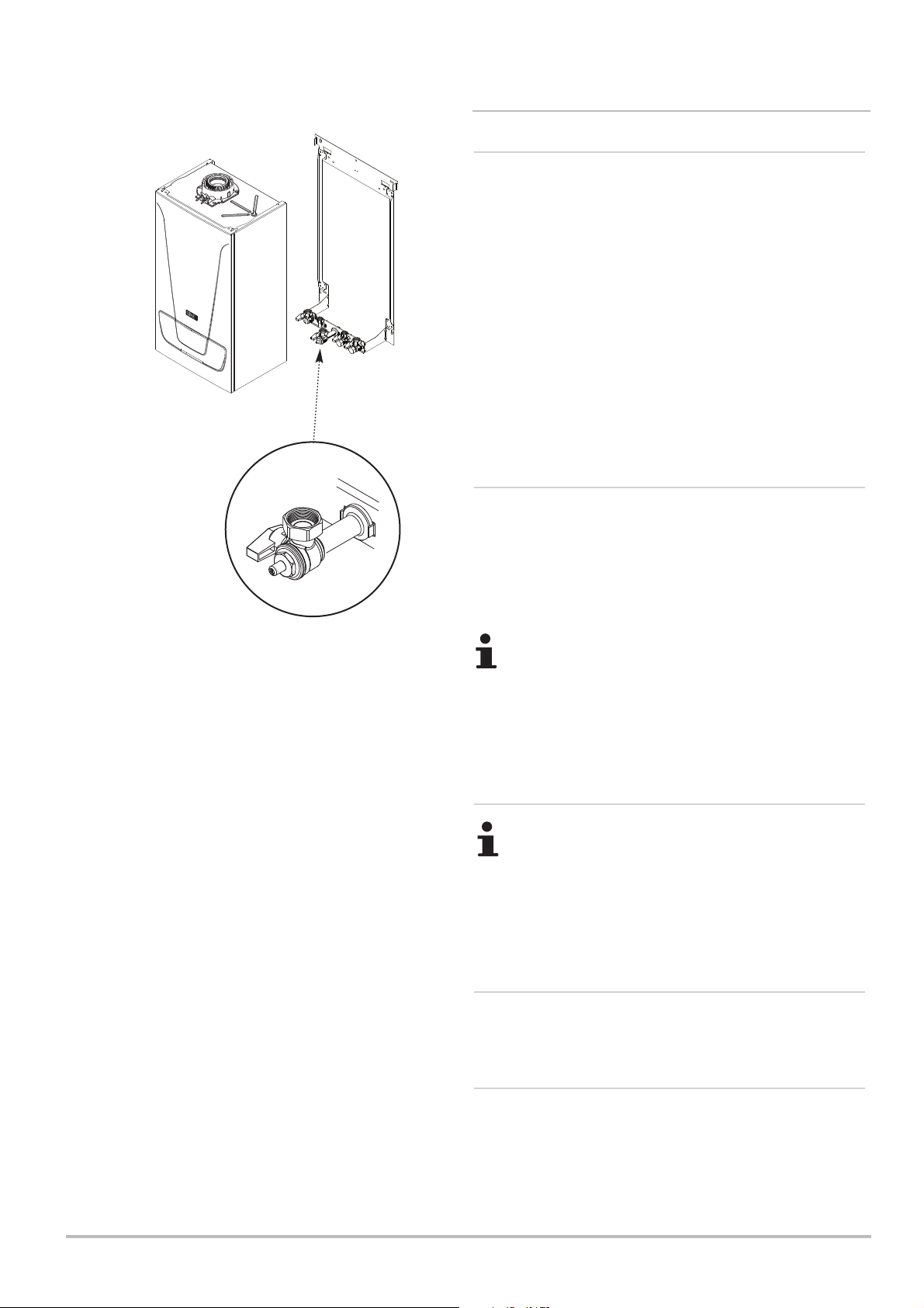
2. The connection to the appliance is a 22mm copper tail
located at the rear of the gas service cock (Fig. 3).
3. Ensure that the pipework from the meter to the appliance is of
adequate size, and the demands of any other gas appliances in
the property are taken into consideration. It is strongly
recommended that pipe of at least 22mm diameter is used.
4. The gas service cock incorporates a pressure test point. The
service cock must be on to check the pressure.
5.2.2 Electrical Supply
Fig. 3
Gas Service Cock
1. External wiring must be correctly earthed, polarised and in
accordance with relevant regulations/rules. In GB this is the
current I.E.E. Wiring Regulations. In IE reference should be
made to the current edition of ETCI rules.
2. The mains supply is 230V ~ 50Hz fused at 3A.
The method of connection to the electricity supply must
facilitate complete electrical isolation of the appliance.
Connection may be via a fused double-pole isolator
with a contact separation of at least 3mm in all poles
and servicing the boiler and system controls only.
5.2.3 Hard Water Areas
Only water that has NOT been artificially softened must
be used when filling or re-pressurising the primary
system. If the mains cold water to the property is fitted
with an artificial softening/treatment device the source
utilised to fill or re-pressurise the system must be
upstream of such a device.
5.2.4 Bypass
1. The boiler is fitted with an automatic integral bypass.
5.2.5 System Control
1. Further external controls (e.g. room thermostat sensors)
MUST be fitted to optimise the economical operation of the
boiler in accordance with Part L of the Building Regulations. A
range of optional controls is available. Full details are contained
in the relevant Sales Literature.
7212136 - 02 (08/14) EcoBlue Plus Combi 25
Page 26

5 Before Installation
5.2.6 Treatment of Water Circulating Systems
1. All recirculatory water systems will be subject to corrosion
unless they are flushed and an appropriate water treatment is
applied. To prevent this, follow the guidelines given in BS 7593
“Treatment of Water in Domestic Hot Water Central Heating
Systems” and the treatment manufacturers instructions.
2. Treatment must involve the use of a proprietary cleanser,
such as Sentinel X300 or X400, or Fernox F3 and an inhibitor
such as Sentinel X100 or Fernox MB-1.
3. Full instructions are supplied with the products. For further
information contact Sentinel (0800 389 4670) or Fernox (0870
870 0362).
Failure to flush and add inhibitor to the system will
invalidate the appliance warranty.
4. It is important to check the inhibitor concentration after
installation, system modification and at every service in
accordance with the inhibitor manufacturer’s instructions. (Test
kits are available from inhibitor stockists.)
5. Complete the label supplied with the inhibitor and attach to
the inside of the boiler case. Detail of system treatment should
be added for future reference.
6. For information or advice regarding any of the above contact
Technical Enquiries 0844 871 1555.
5.2.7 Showers
1. If a shower control is supplied from the appliance it should be
of the thermostatic or pressure balanced type. Thermostatic
type shower valves provide the best comfort and guard against
water at too high a temperature. Existing controls may not be
suitable - refer to the shower valve manufacturer.
5.2.8 Expansion Vessel (CH only)
1. The appliance expansion vessel is pre-charged to 1.0 bar.
Therefore, the minimum cold fill pressure is 1.0 bar. The vessel
is suitable for correct operation for system capacities up to
100 litres. For greater system capacities an additional
expansion vessel must be fitted.
For GB refer to BS 7074 Pt 1. For IE, the current edition of I.S.
813 “Domestic Gas Installations”.
2. Checking the charge pressure of the vessel - to check the
charge accurately ensure the system is cold. It is also
necessary to relieve the pressure by draining the boiler. Using a
suitable gauge check the pressure at the valve on the underside
of the vessel. Adjust the pressure as required and repressurise
the system.
26 EcoBlue Plus Combi 7212136 - 02 (08/14)
Page 27
Before Installation 5
5.2.9 Safety Pressure Relief Valve
See B.S. 6798 for full details.
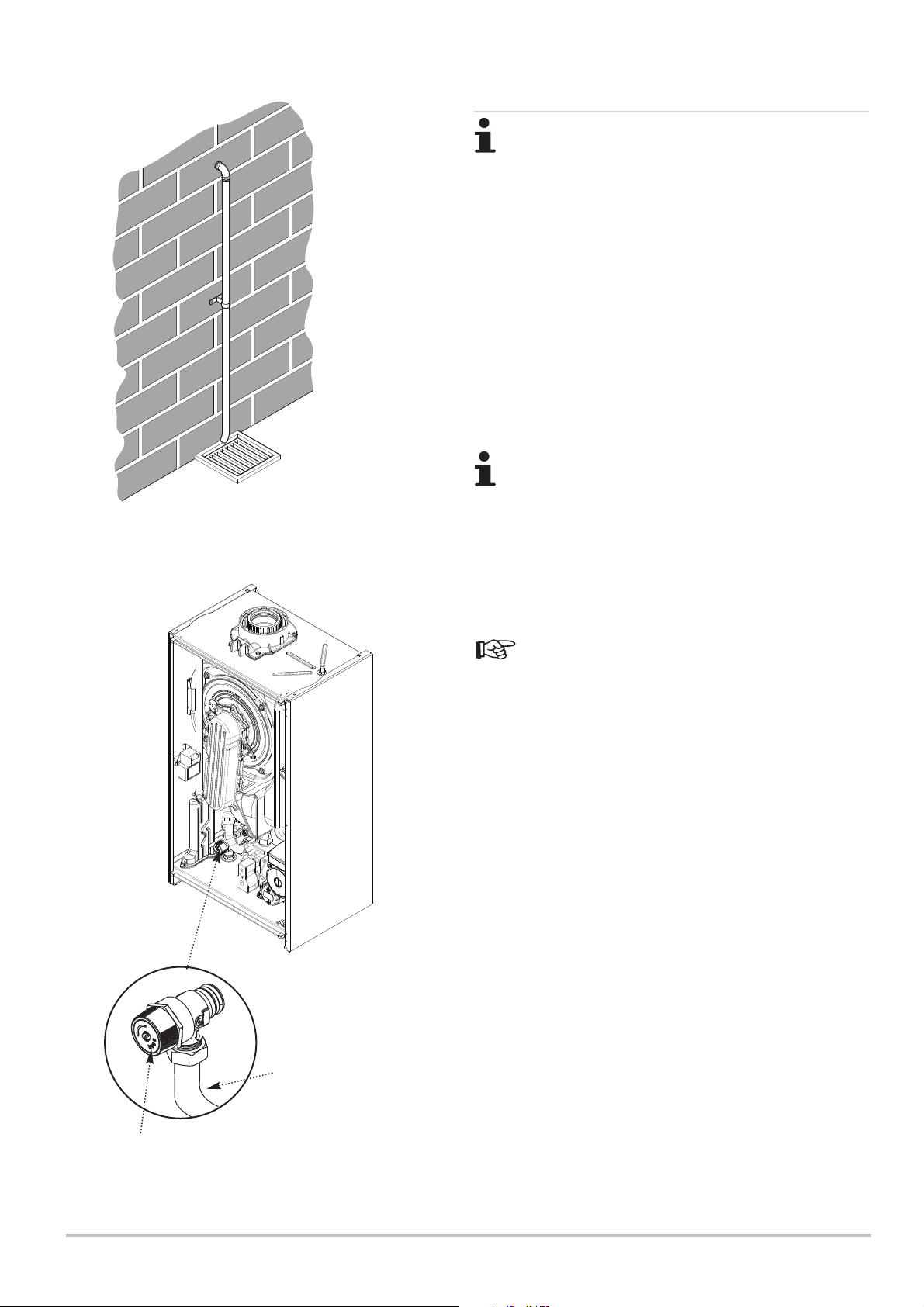
1. The pressure relief valve (Fig. 5) is set at 3 bar, therefore all
pipework, fittings, etc. should be suitable for pressures in
excess of 3 bar and temperature in excess of 100°C.
2. The pressure relief discharge pipe should be not less than
15mm diameter, run continuously downward, and discharge
outside the building, preferably over a drain. It should be routed
in such a manner that no hazard occurs to occupants or causes
damage to wiring or electrical components. The end of the pipe
should terminate facing down and towards the wall (Fig. 4).
3. The discharge must not be above a window, entrance or
other public access. Consideration must be given to the
possibility that boiling water/steam could discharge from the
pipe.
The relief valve must never be used to drain the system
The end of the pipe should terminate facing
down and towards the wall
Fig. 4
4. A remote relief valve kit is available to enable the boiler to be
installed in cellars or similar locations below outside ground
level.
5. A boiler discharge pump is available which will dispose of
both condensate & high temperature water from the relief valve.
It has a maximum head of 5 metres.
Section 6.2.1 gives details of how to connect the pipe
to the boiler.
Control Box
removed for clarity
Discharge Pipe
Pressure Relief Valve
7212136 - 02 (08/14) EcoBlue Plus Combi 27
Fig.5
Page 28
5 Before Installation
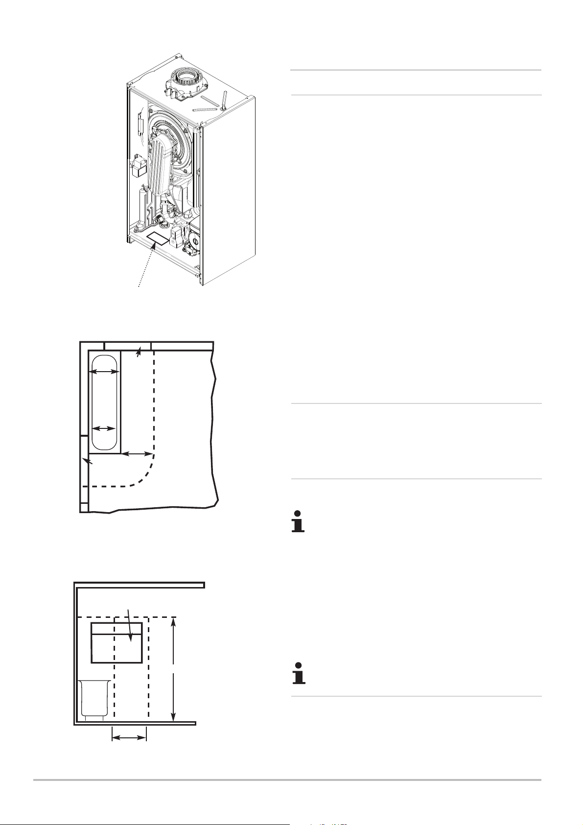
Fig. 6
Data Badge
Zone 2
Zone 1
Window
Recess
Zone 2
5.3 Choice of the Location
5.3.1 Location of the Appliance
1. The boiler may be fitted to any suitable wall with the flue
passing through an outside wall or roof and discharging to
atmosphere in a position permitting satisfactory removal of
combustion products and providing an adequate air supply. The
boiler should be fitted within the building unless otherwise
protected by a suitable enclosure i.e. garage or outhouse. (The
boiler may be fitted inside a cupboard-see Section 5.3.4).
2. Where the boiler is sited in an unheated enclosure and during
periods when the heating system is to be unused it is
recommended that the permanent live is left on to give BOILER
frost protection. NOTE: THIS WILL NOT PROTECT THE
SYSTEM !
3. If the boiler is fitted in a room containing a bath or shower
reference must be made to the relevant requirements.
In GB this is the current I.E.E. Wiring Regulations and Building
Regulations.
In IE reference should be made to the current edition of I.S. 813
“Domestic Gas Installations” and the current ETCI rules.
4. If the boiler is to be fitted into a building of timber frame
construction then reference must be made to the current edition
of Institute of Gas Engineers Publication IGE/UP/7 (Gas
Installations in Timber Framed Housing).
Zone 0
Fig. A
Zone 1
Window
Recess
Zone 2
Window Recess
Zone 2
Zone 2
0.6 m
In GB Only
2.25 m
Ceiling
Outside Zones
5.3.2 Data Plate
1. The boiler data badge gives details of the model, serial
number and Gas Council number and is situated on the boiler
lower panel. It is visible when the control box is lowered (Fig. 6).
5.3.3 Bath & Shower Rooms
Where an integral timer is NOT FITTED the boiler has a
protection rating of IPX5D and if installed in a room
containing a bath or shower can be within Zone 2 (but
not 0 or 1).
Figs. A & B shows zone dimensions for a bathtub. For other
examples refer to the Current I.E.E. Wiring Regulations).
Reference must be made to the relevant requirements.
In GB this is the current I.E.E. Wiring Regulations and Building
Regulations. In IE reference should be made to the current
edition of I.S. 813 “Domestic Gas Installations” and the current
ETCI rules.
If the boiler is fitted with an integral timer it CANNOT be
installed in Zone 0, 1 or 2.
Zone 0
5.3.4 Ventilation
0.6 m
Fig. B
28 EcoBlue Plus Combi 7212136 - 02 (08/14)
In GB Only
1. Where the appliance is installed in a cupboard or
compartment, no air vents are required. BS 5440: Part 2 refers
to room sealed appliances installed in compartments. The
appliance will run sufficiently cool without ventilation.
Page 29
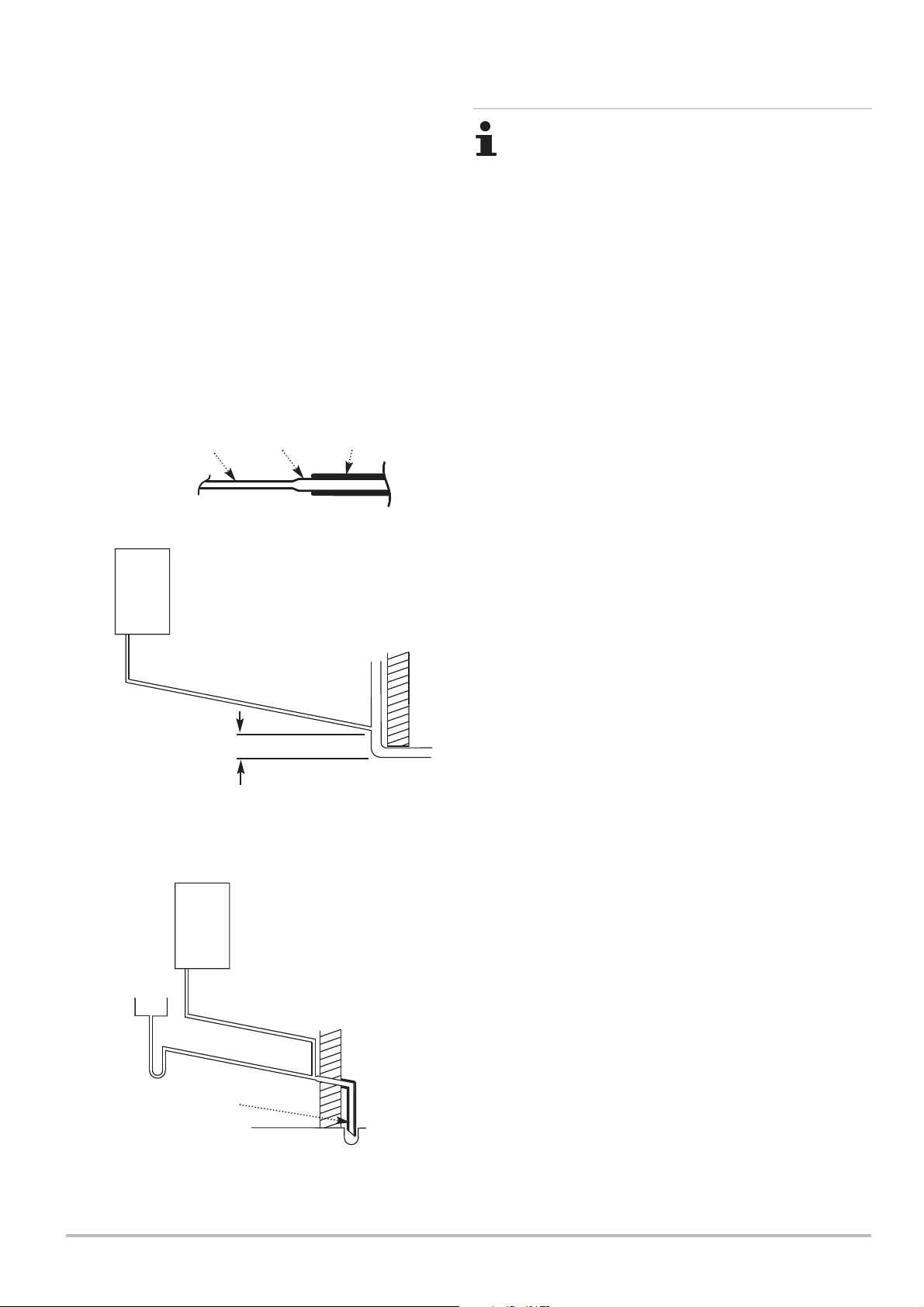
Before Installation 5
Examples are shown of the following methods of
termination:i) to an internal soil & vent pipe
ii) via an internal discharge branch (e.g. sink waste)
downstream of the trap
iii) to a drain or gully
iv) to a purpose made soakaway
v) pumped into an internal discharge branch (e.g.
sink waste) downstream of the trap
vi) pumped into an external soil & vent pipe
vii) to a drain or gully with extended external run &
trace heating
It is strongly recommended to discharge
internally into the household drainage system. If
connecting to a rain water drain, that drain MUST
discharge into a foul drain.
Insulation
Key to
Pipework
21.5mm
32mm
5.3.5 Condensate Drain
FAILURE TO INSTALL THE CONDENSATE
DISCHARGE PIPEWORK CORRECTLY WILL AFFECT
THE RELIABLE OPERATION OF THE BOILER.
CAREFUL CONSIDERATION MUST BE GIVEN TO
THE POSSIBILITY OF THE PIPEWORK BEING
SUBJECT TO FREEZING CONDITIONS AND
APPROPRIATE MEASURES TAKEN TO PREVENT
BLOCKAGE. CORRECT INSTALLATION IN
ACCORDANCE WITH THIS SECTION WILL
CONSIDERABLY MINIMISE THE LIKELIHOOD OF
BLOCKAGE AND SUBSEQUENT BOILER LOCK-OUT.
A CONDENSATE DISCHARGE PUMP AND PIPE
‘TRACE HEATING’ ARE AVAILABLE AS
ACCESSORIES - see paragraphs 5.3.6.12 to 5.3.6.15
for further details.
The condensate discharge pipe MUST NOT RISE at
any point along its length. There MUST be a fall of AT
LEAST 2.5° (50mm per metre) along the entire run
EXCEPT when employing a suitable condensate pump
in basement and cellar or similar applications.
i) Termination to an internal soil
50mm per metre of pipe run
2.5° Minimum fall
450mm min*
*450mm is applicable to properties up
to 3 storeys.
For multi-storey building installations
consult BS 6798.
ii) External termination via
internal discharge branch
e.g sink waste - downstream*
50mm per metre
Sink
Boiler
of pipe run
2.5° Minimum fall
and vent pipe
The boiler condensate trap incorporates a seal of
75mm, therefore it is unnecessary to install an air break
and trap in the discharge pipework.
1. The condensate outlet will accept 21.5mm (
3
/4in) plastic
overflow pipe. It is strongly recommended that this
discharges internally into the household drainage system.
Where this is not possible, discharge into an outside drain is
permissible providing every possible precaution is taken to
prevent freezing.
2. Ensure the discharge of condensate complies with any
national or local regulations in force. BS 6798 & Part H1 of the
Building Regulations give further detailed guidance.
3. The discharge pipe should be run in a proprietary drain pipe
material e.g. PVC, PVC-U, ABS, PVC-C or PP.
4. Metal pipework is NOT suitable for use in condensate
discharge systems.
5. The pipe should be a minimum of 21.5mm diameter and must
be supported using suitably spaced clips of the correct design to
prevent sagging.
6. It is advisable that the full length of condensate pipe is
run internally and preferably be less than 3 metres.
Pipe must terminate
above water level but
below surrounding
surface. Cut end at 45°
7. Internal runs greater than 3 metres or runs in cold areas
should use 32mm waste pipe.
8. External runs MUST be a MINIMUM of 32mm and fully
insulated with material suitable for external use.
*It is NOT RECOMMENDED to connect upstream
of the sink or other waste water receptacle !
7212136 - 02 (08/14) EcoBlue Plus Combi 29
Page 30
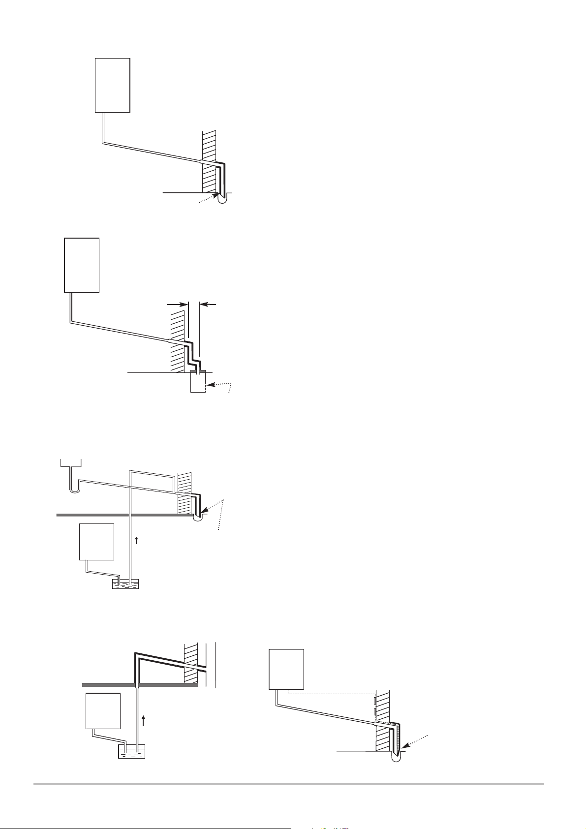
5 Before Installation
Boiler
2.5° Minimum fall
Pipe must terminate above water level
but below surrounding surface. Cut
end at 45°
iv) Termination to a purpose made
soakaway
Further specific requirements for
Boiler
soakaway design are referred to in
BS 6798.
iii) Termination to a drain
or gully
50mm per metre
of pipe run
9. If the boiler is fitted in an unheated location the entire
condensate discharge pipe should be treated as an external run
and sized and insulated accordingly.
10. In all cases discharge pipe must be installed to aid disposal
of the condensate. To reduce the risk of condensate being
trapped, as few bends and fittings as possible should be used
and any burrs on cut pipe removed.
11. When discharging condensate into a soil stack or waste
pipe the effects of existing plumbing must be considered. If soil
pipes or waste pipes are subjected to internal pressure
fluctuations when WC's are flushed or sinks emptied then backpressure may force water out of the boiler trap and cause
appliance lockout.
12. A boiler discharge pump is available which will dispose of
both condensate & high temperature water from the relief valve.
It has a maximum head of 5 metres. Follow the instructions
supplied with the pump.
50mm per metre
of pipe run
2.5° Minimum fall
Holes in the soak-away must
face away from the building
v) pumped into an internal discharge branch
(e.g. sink waste) downstream of the trap
Sink
50mm per metre of pipe run
2.5° Minimum fall
Basement or
Boiler
similar
(heated)
Condensate Pump
Pipe must terminate
above water level but
below surrounding
surface. Cut end at 45°
500mm min
13. Condensate Drain Pipe ‘Trace Heating’ Elements are
available in various lengths, 1, 2, 3 & 5 metres. Where the drain
is between 3 & 5 metres a 5 metre kit can be used and
“doubled back” upon itself.
14. It is possible to fit the element externally on the condensate
drain or internally as detailed in the instructions provided.
15. The fitting of a ‘Trace Heating’ Element is NOT a substitute
for correct installation of the condensate drain. ALL
requirements in this section must still be adhered to.
vi) pumped into an external soil & vent pipe
50mm per metre of pipe run
2.5° Minimum fall
Unheated Location
(e.g. Garage)
Basement or similar
Boiler
30 EcoBlue Plus Combi 7212136 - 02 (08/14)
(heated)
Condensate
Pump
vii) to a drain or gully with extended
external run & trace heating
The ‘Trace Heating’ element must be installed in
Boiler
50mm per metre of pipe run
2.5° Minimum fall
accordance with the instructions supplied.
External runs & those in unheated locations still
require insulation.
Pipe must terminate
above water level but
below surrounding
surface. Cut end at 45°
Page 31
Before Installation 5
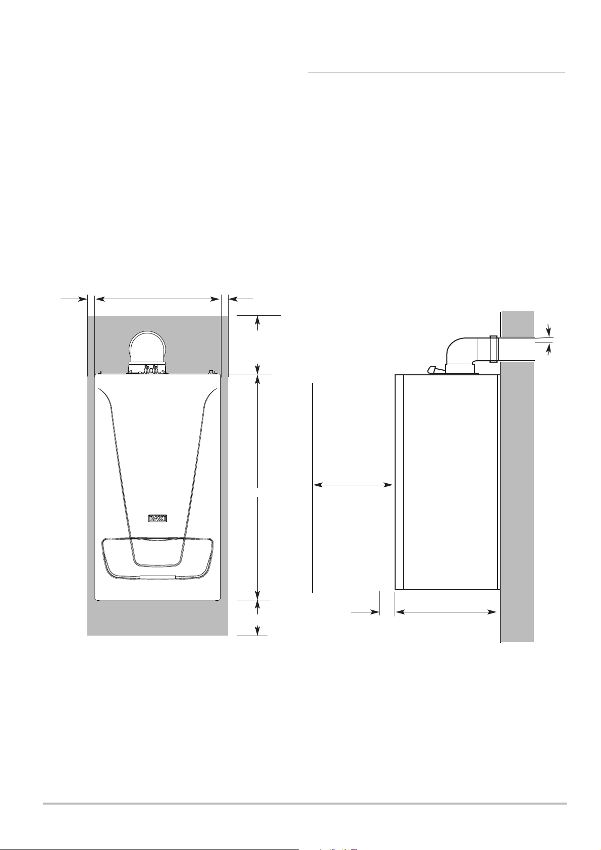
5.3.6 Clearances
1. A flat vertical area is required for the installation of the boiler.
2. These dimensions include the necessary clearances around
the boiler for case removal, spanner access and air movement.
Additional clearances may be required for the passage of pipes
around local obstructions such as joists running parallel to the
front face of the boiler.
*This is MINIMUM recommended dimension. Greater clearance
will aid installation and maintenance.
5mm Min
390mm
5mm Min
175 mm Min (300mm
Min if using 80/125mm
flueing system)
700mm
At least
1.5°
450mm Min
For Servicing
Purposes &
Operating the
Controls
5mm Min
150mm* Min
*This is MINIMUM
recommended dimension.
Greater clearance will aid
installation and maintenance.
7212136 - 02 (08/14) EcoBlue Plus Combi 31
In Operation
Fig.7
295mm
Page 32
5 Before Installation
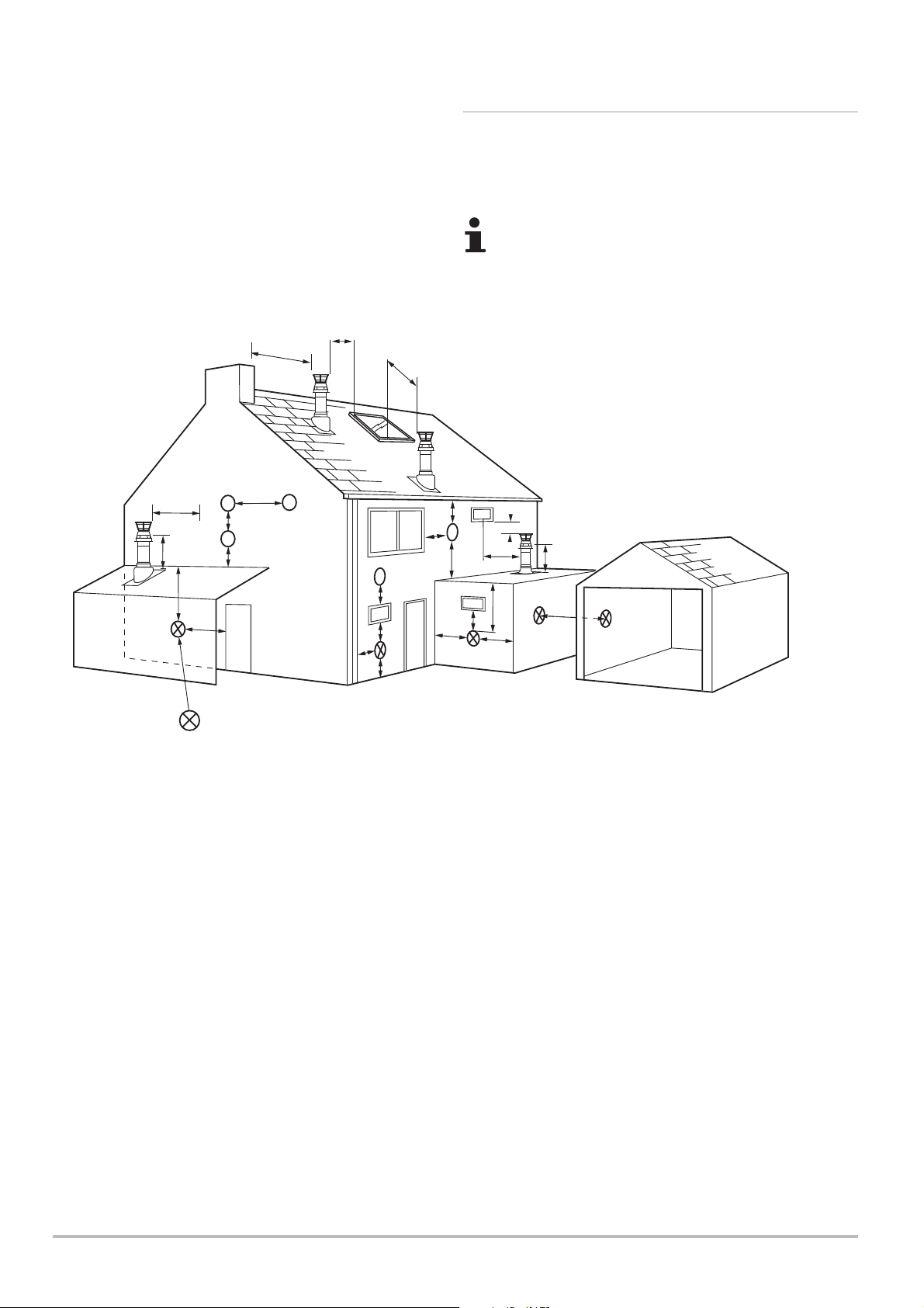
5.3.7 Flue/Chimney Location
1. The following guidelines indicate the general requirements for
siting balanced flue terminals. For GB recommendations are
given in BS 5440 Pt 1. For IE recommendations are given in the
current edition of I.S. 813 “Domestic Gas Installations”.
Due to the nature of the boiler a plume of water vapour
will be discharged from the flue. This should be taken
into account when siting the flue terminal.
R
N
M
I
I
F
L
Likely flue positions requiring
a flue terminal guard
J,K
T
U
D
C
E
I
A
S
I
B
F
A
G
A
H
H
J,K
I
Fig. 8
Terminal Position with Minimum Distance (Fig. 8) (mm)
1
Directly below an opening, air brick, opening windows, etc. 300
A
1
B
Above an opening, air brick, opening window etc. 300
1
C
Horizontally to an opening, air brick, opening window etc. 300
2
D
Below gutters, soil pipes or drain pipes. 25 (75)
2
E
Below eaves. 25 (200)
2
F
Below balconies or car port roof. 25 (200)
2
G
From a vertical drain pipe or soil pipe. 25 (150)
2
H
From an internal or external corner. 25 (300)
I Above ground, roof or balcony level. 300
J From a surface or boundary line facing a terminal. 600
K From a terminal facing a terminal (Horizontal flue). 1200
From a terminal facing a terminal (Vertical flue). 600
L From an opening in carport (e.g. door, window)
into the dwelling. 1200
M Vertically from a terminal on the same wall. 1500
N Horizontally from a terminal on the same wall. 300
R From adjacent wall to flue (vertical only). 300
S From an adjacent opening window (vertical only). 1000
T Adjacent to windows or openings on pitched and flat roofs 600
U Below windows or openings on pitched roofs 2000
1
In addition, the terminal should be no nearer than
150 mm to an opening in the building fabric formed
for the purpose of accommodating a built-in element
such as a window frame.
2
Only ONE 25mm clearance is allowed per
installation. If one of the dimensions D, E, F, G or H
is 25mm then the remainder MUST be as shown in
brackets, in accordance with B.S.5440-1.
32 EcoBlue Plus Combi 7212136 - 02 (08/14)
Page 33
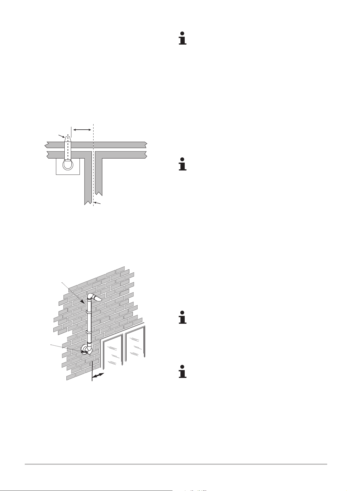
Te r m i nal
Assembly
Top View Rear Flue
300 min
Before Installation 5
Under car ports we recommend the use of the plume
displacement kit. The terminal position must ensure the
safe and nuisance - free dispersal of combustion
products.
2. If the terminal discharges onto a pathway or passageway,
check that combustion products will not cause a nuisance and
that the terminal will not obstruct the passageway.
3. If a terminal is less than 2 metres above a balcony, above
ground or above a flat roof to which people have access, then a
suitable terminal guard must be provided.
*
*4. Reduction to the boundary is possible down to 25mm but
the flue deflector must be used (see 5.3.12).
The distance from a fanned draught appliance terminal
installed parallel to a boundary may not be less than
300mm in accordance with the diagram opposite
(Fig. 9).
Fig. 9
Plume
Displacement
Kit
Air Inlet
Property Boundar y Line
If fitting a Plume Displacement Flue Kit, the air inlet
must be a minimum of 150mm from any opening
windows or doors (see Fig. 10).
Opening
Window or Door
Fig. 10
7212136 - 02 (08/14) EcoBlue Plus Combi 33
150mm
MIN.
The Plume Displacement flue gas discharge terminal
and air inlet must always terminate in the same
pressure zone i.e. on the same facing wall.
Page 34
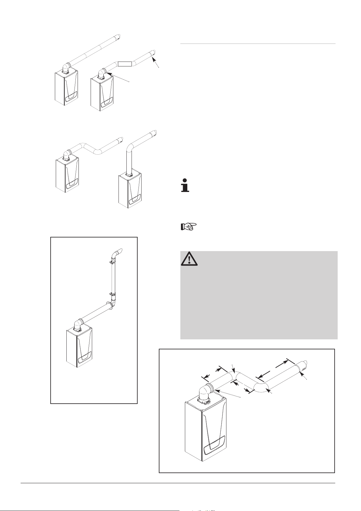
5 Before Installation
5.3.8 Horizontal Flue/Chimney Systems
1. The standard telescopic flue is suitable only for horizontal
termination applications.
(ii)
(i)
2. All fittings should be fully engaged. The approximate
engagement is 40mm. Apply the lubricant supplied to the seal on
each fitting to aid assembly.
3. Maximum permissible equivalent flue lengths are: (60/100) (80/125)
Horizontal Concentric 10 metres 20 metres
4. Any additional “in line” bends in the flue system must be taken
into consideration.
Their equivalent lengths are:Concentric Pipes:
135° bend 0.5 metres
93° bend 1.0 metres
Flue length is measured from point (i) to (ii) as shown.
The elbow supplied with the standard horizontal
telescopic flue kit is not included in any equivalent
length calculations.
Horizontal
Flues
Plume Displacement Kit 60 /100 dia
1M Extensions 45° & 93° elbows are
also available - see the separate Flue
Guide.
Read this section in conjunction with the Flue
Installation Guide supplied with the boiler.
WARNING
SUPPORT - All flue systems MUST be securely
supported at a MINIMUM of once every metre &
every change of direction. It is recommended that
every straight piece is supported irrespective of
length. Additional supports are available as
accessories.
VOIDS - Consideration must be given to flue systems
in voids and the provision of adequate access for
subsequent periodic visual inspection.
This bend is
equivalent to 1 metre
A
C
(ii)
B
(i)
This bend is equivalent
to 1 metre
Total equivalent length =
A+B+C+2 x 90° Bends
NOTE: Horizontal flue pipes should
always be installed with a fall of at least
1.5° from the terminal to allow
condensate to run back to the boiler.
34 EcoBlue Plus Combi 7212136 - 02 (08/14)
Page 35
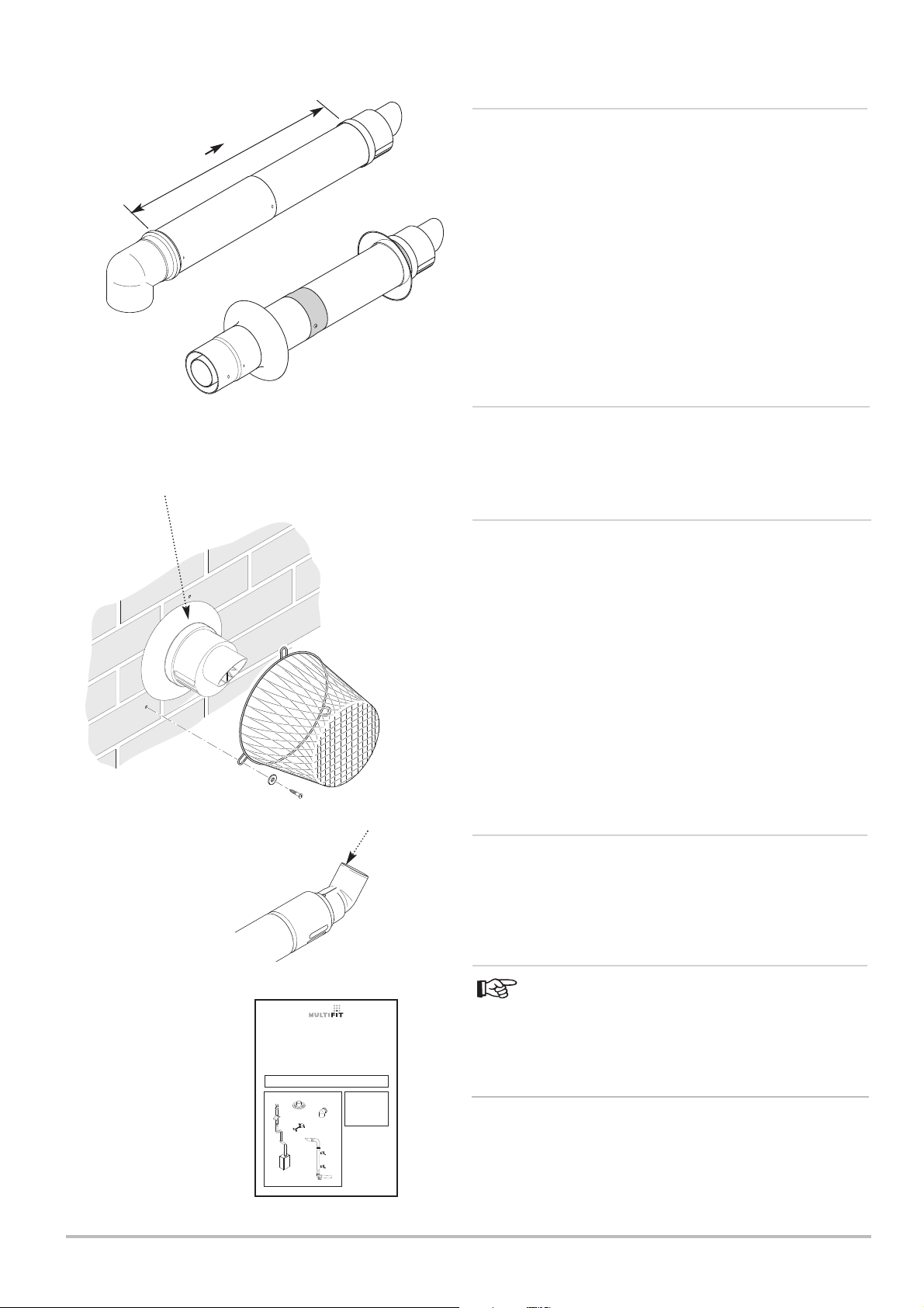
5.3.9 Flue/Chimney Lengths
Before Installation 5
315mm
Fig. 11
Ensure that no part of
the white outer chimney
duct is visible
500mm
1. The standard horizontal telescopic flue kit allows for lengths
between 315mm and 500mm from elbow to terminal without the
need for cutting (Fig. 11). Extensions of 250mm, 500mm & 1m
are available.
The maximum permissible equivalent flue length is:
10 metres (60/100 system - vertical & horizontal)
20 metres (80/125 system - vertical & horizontal)
15 metres (80/80 twin pipe)
8 metres (60/100 system - vertical connected to ridge
terminal)
5.3.10 Flue/Chimney Trim
1. The flexible flue trims supplied can be fitted on the outer and
inner faces of the wall of installation.
5.3.11 Terminal Guard
1. When codes of practice dictate the use of terminal guards
(Fig. 12) ‘Multifit’ accessory part no. 720627901 can be used
(NOTE: This is not compatible with Flue Deflector referred to
below).
Fig. 12
Flue Deflector
Fig. 13
(Ø 60/100 Flue Systems)
IMPORTANT NOTE:This document
will assist in the correct installation of
the various flue & chimney systems
described within. However, it is the
responsibility of the installer/Gas Safe
registered commissioning engineer to
ensure that the flue & chimney system
is fitted safely and in compliance with
the relevant standards and practices in
force in the country of installation.
Please leave these instructions with the
Installation & Servicing Instructions.
GUIDANCE NOTES
Flue Accessories & Fitting Guide
Ø 60/100 Flue Systems
Ø 80/125 Flue Systems
Ø 80/80 Twin Flue Systems
Plume Displacement Kit
READ THESE INSTRUCTIONS IN CONJUNCTION WITH THE BOILER
INSTALLATION INSTRUCTIONS BEFORE FITTING THE FLUE
© Baxi Heating UK Ltd 2011
2. There must be a clearance of at least 50mm between any
part of the terminal and the guard.
3. When ordering a terminal guard, quote the appliance name
and model number.
4. The flue terminal guard should be positioned centrally over
the terminal and fixed as illustrated.
5.3.12 Flue/Chimney Deflector
1. Push the flue deflector over the terminal end. It may point
upwards as shown, or up to 45° either way from vertical. Secure
the deflector to the terminal with screws provided (Fig. 13).
5.3.13 Flue/Chimney Accessories
For full details of Flue Accessories (elbows, extensions,
clamps etc.) refer to the Flue Installation Guide supplied in the
literature pack.
5.4 Transport
1. This product should be lifted and handled by two people.
When lifting always keep your back straight and wear protective
equipment where necessary. Carrying and lifting equipment
should be used as required. e.g. when install in a loft.
7212136 - 02 (08/14) EcoBlue Plus Combi 35
Page 36
5 Before Installation
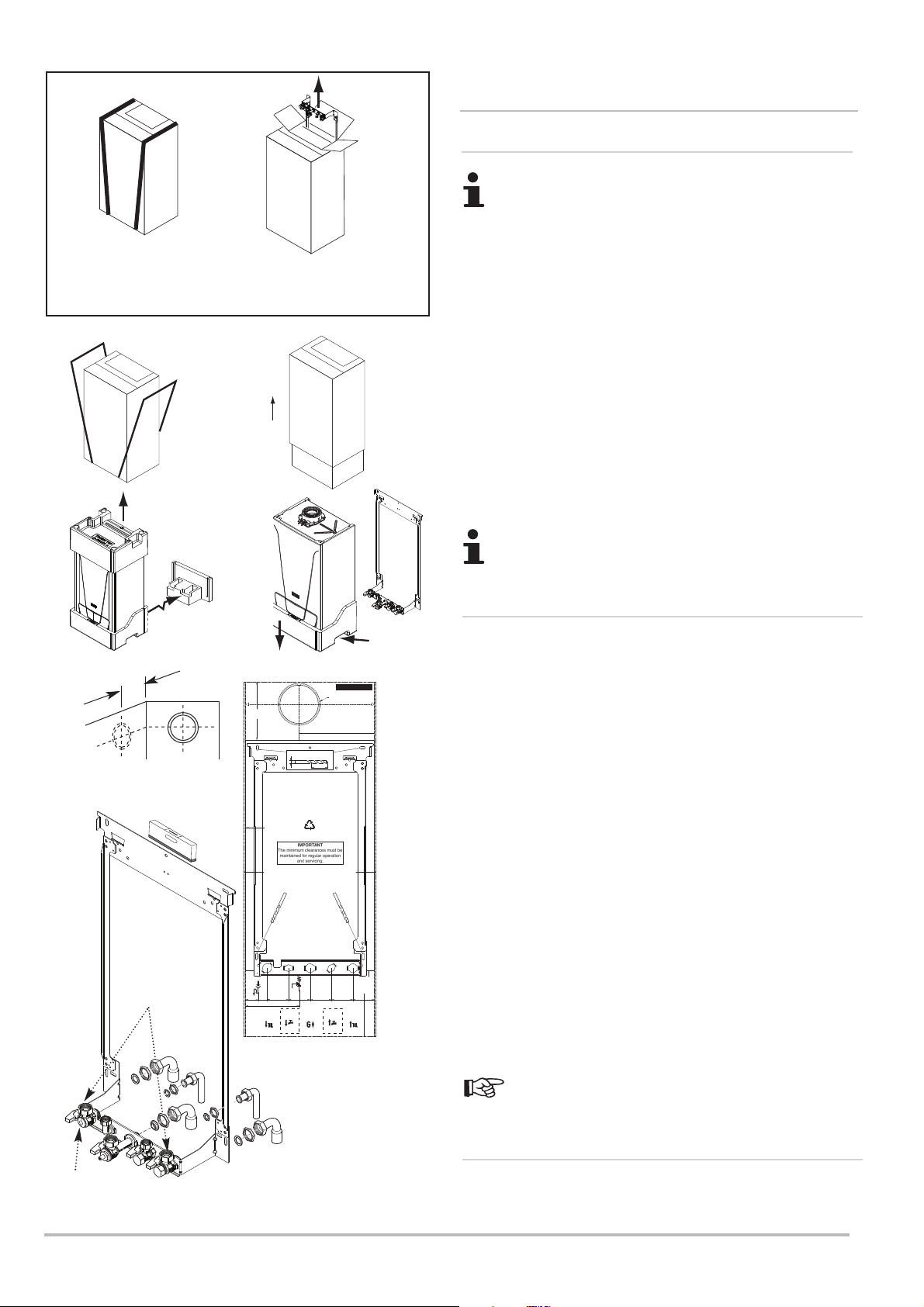
LIFT HERE
BOTH SIDES
Pre-plumbing Fig. 14
To remove only the Wall jig
slide banding to the edge
and open flaps.
Slide the wall jig out of
carton then close the flaps.
Slide banding back on.
5.5 Unpacking & Initial Preparation
5.5.1 Unpacking
RISK ASSESSMENT - Before commencing the
installation it is recommended that the ‘Five Steps to
Risk Assessment’ document published by the HSE is
consulted, and an assessment performed as described.
GAS SUPPLY - The gas supply, gas type and pressure
must be checked for suitability before connection.
1. See ‘Section 2.3.1 Handling’ before unpacking or lifting the
boiler.
2. Follow the procedure on the carton to unpack the boiler or see
Fig. 14a.
3. If pre-plumbing (Fig. 14) - the wall jig and fitting kit can be
removed without removing the carton sleeve. Simply slide
banding to the edge and open the perforated flap, lift out the jig,
fitting kit and instructions. If the boiler is to be install at a later
date, close the flap and reposition the banding straps, the boiler
can now be store safely away.
Fig. 15
SNAP OFF
130mm
For Side Flue Exit
3/4” BSP
Connections
Fig. 14a
175 mm
Minimum
Clearance
Vertical Flue
Centre Line
Boiler Wall Mounting Plate
Fixing Slots
Ø 8 mm
Profile of
Outercase
5 mm Minimum
Side Clearance
Condensate
Pressure
Drain
Relief
Valve
(15mm)
26.5
38.5mm
mm
65 mm 65 mm 65 mm 65 mm 65 mm
162.5mm (PRV)
Hot Water
Heating
Outlet
Flow
(22mm)
(15mm)
(22mm)
Combi Only
Not System
Part No. 7212143 DRAFT A
Wall Template
50 mm
Gas
Inlet
Part No. 7212143
116mm Dia Minimum
Aperture For Flue Tube
228 mm
5 mm Minimum
Side Clearance
Cold Water
Inlet
(15mm)
Combi Only
Not System
Side Flue
Centre Line
200 mm
Recommended
150 mm
Minimum
Clearance
Heating
Return
(22mm)
Fig. 17
A small amount of water may drain from the boiler in the
upright position.
5.5.2 Initial Preparation
1. After considering the location position the fixing template on
the wall ensuring it is level both horizontally and vertically.
2. Mark the position of the fixing slots for the wall jig indicated on
the template.
3. Mark the position of the centre of the flue hole (rear exit). For
side flue exit, mark as shown (Fig. 15).
4. If required, mark the position of the gas and water pipes.
Remove the template (Fig. 17).
5. Cut the hole for the flue (minimum diameter 116mm).
6. Drill the wall as previously marked to accept the wall plugs
supplied. Secure the wall jig using the fixing screws.
7. Using a spirit level ensure that the wall jig is level before
finally tightening the screws (Fig. 16).
8. Connect the gas and water pipes to the valves on the wall
mounting plate using the copper tails supplied. Ensure that the
sealing washers are fitted between the connections.
Fit the filling loop as described in the instructions
supplied with it.
5.5.3 Flushing
Heating Flow
Fig.16
36 EcoBlue Plus Combi 7212136 - 02 (08/14)
1. Flush thoroughly and treat the system according to guidance
given in B.S. 7593.
Page 37
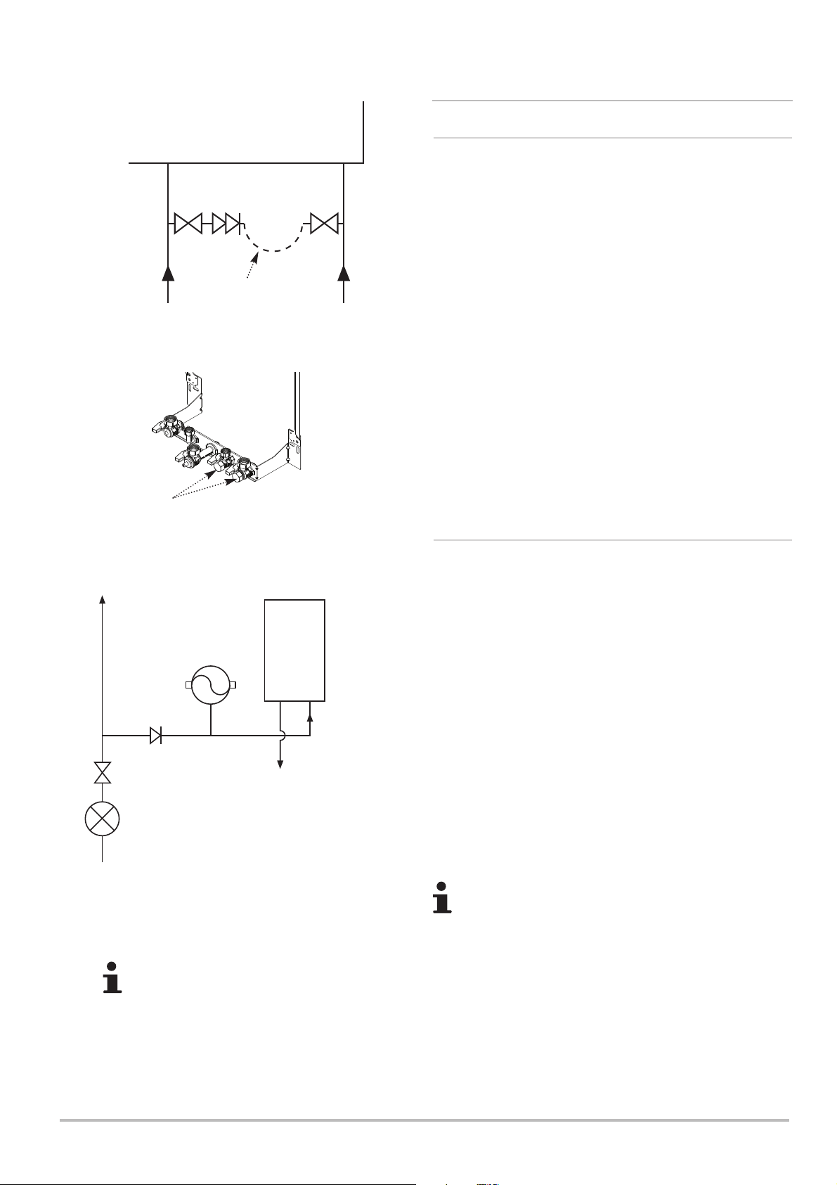
Stop
Valve
Double
Check
Valve
Stop
Valve
Before Installation 5
5.6 Connecting Diagrams
5.6.1 System Filling and Pressurising
1. A filling point connection on the central heating return pipework
must be provided to facilitate initial filling and pressurising and
also any subsequent water loss replacement/refilling.
2. A filling loop is supplied with the boiler. Follow the instructions
provided with it.
Fig. 18
Filling Loop
Connections
Other Tap
Outlets
DHW
Mains
Inlet
Expansion
Vessel*
Temporary
Loop
Boiler
CH
Return
3. The filling method adopted must be in accordance with all
relevant water supply regulations and use approved equipment.
4. Your attention is drawn to:
for GB: Guidance G24.2 and recommendation R24.2 of the Water
Regulations Guide.
for IE: the current edition of I.S. 813 “Domestic Gas Installations”.
5. The sealed primary circuits may be filled or replenished by
means of a temporary connection between the circuit and a
supply pipe, provided a ‘Listed’ double check valve or some other
no less effective backflow prevention device is permanently
connected at the inlet to the circuit and the temporary connection
is removed after use.
5.6.2 Domestic Hot Water Circuit
1. All DHW circuits, connections, fittings, etc. should be fully in
accordance with relevant standards and water supply regulations.
2. Your attention is drawn to:
for GB: Guidance G17 to G24 and recommendation R17 to R24
of the Water Regulations Guide.
for IE: the current edition of I.S. 813 “Domestic Gas Installations”.
Pressure
Reducer Valve*
Fig. 19
Check
Valve*
To Hot
Taps
Stop Tap
*See 5.6.2. for instances
when these items may be
required
Where Low Flow Taps or Fittings are intended
to be used in the DHW system connected to a
Baxi EcoBlue Plus Combi it is strongly
recommended that the DHW flow rate DOES
NOT fall below 2.5l/min. This will ensure
reliable operation of the DHW function.
3. The Water Regulations recommendations for England and
Wales prohibits backflow from appliances into the wholesome
water supply due to thermal expansion. However this type of
instantaneous combination boiler, with less than 15 litres of stored
capacity, does not require any backflow prevention device as any
thermal expansion is accommodated within the appliance.
It is possible in certain circumstances that other cold water
demands (e.g. washing machines, flushing of W.C.s) may affect
the DHW function of the boiler. In these instances the fitting of a
backflow prevention device and expansion vessel is
recommended.
If a check valve, loose jumpered stop cock, water meter
or water treatment device is fitted (or may be in the
future) to the wholesome water supply connected to the
boiler domestic hot water (DHW) inlet supply then a
suitable expansion device may be required.
4. The boiler’s maximum working mains pressure is 8 bar,
therefore all pipework, connections, fittings, etc. should be
suitable for pressures in excess of 8 bar. A pressure reducing
valve must be fitted for pressures in excess of 8 bar. The
manufacturer of any outlet fittings, such as a shower valve, may
require a lower maximum pressure. The pressure reduction must
take account of all fittings connected to the DHW system.
7212136 - 02 (08/14) EcoBlue Plus Combi 37
Page 38
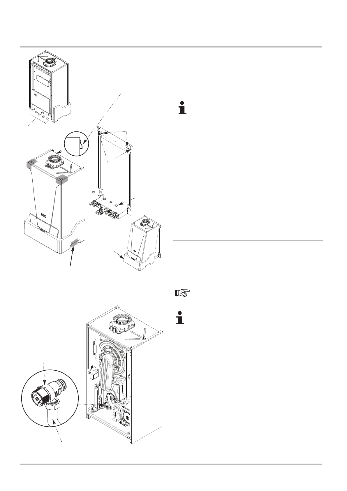
6 Installation
6 Installation
Remove Sealing Caps
from under the Boiler
before lifting into
position
Engage the Boiler Mounting
Bracket on the Boiler into the
Retaining Lugs using the
Aligning Lugs for position
Retaining
Lugs
Aligning
Lugs
Sealing
Washers (x 5)
6.1 General
1. Remove the sealing caps from the boiler connections under
the boiler (including the condensate trap) before lifting into
position.
A small amount of water may drain from the boiler once
the caps are removed. For ease of installation connect
and tighten the copper tails to the valves on the wall
plate BEFORE fitting the boiler !
2. Lift the boiler as indicated by the shaded areas. The boiler
should be lifted by TWO PEOPLE. Engage the mounting bracket
at the top rear of the boiler into the retaining lugs on the wall jig
using the aligning lugs for position (Fig.21) (see ‘Handling’
section 2.3.1).
3. Insert the sealing washers between the valves and pipes on
the wall jig and the boiler connections.
4. Tighten all the connections.
Lift Here
Both Sides
Pressure Relief Valve
Bottom
Polystyrene
Fig. 21
When the Boiler Mounting Bracket on
the Boiler is in position on the
Retaining Lugs, the bottom polystyrene
may be discarded allowing the boiler to
swing into position
6.2 Assembly
6.2.1 Fitting the Pressure Relief Discharge Pipe
1. Remove the discharge pipe from the kit.
2. Determine the routing of the discharge pipe in the vicinity of
the boiler. Make up as much of the pipework as is practical,
including the discharge pipe supplied.
Note the intended position of the pipe is between the hot
water outlet and gas inlet pipes - see Section 3.2
Make all soldered joints before connecting to the
pressure relief valve. Do not adjust the position of the
valve. The discharge pipe must be installed before
pressurising the system.
3. The pipework must be at least 15mm diameter and run
continuously downwards to a discharge point outside the
building. See section 5.2.9 for further details.
4. Utilising one of the sealing washers, connect the discharge
pipe to the adaptor and tighten the nut hand tight, plus 1/4 turn to
seal.
5. Complete the discharge pipework and route it to the outside
discharge point.
Fig. 22
Discharge Pipe
38 EcoBlue Plus Combi 7212136 - 02 (08/14)
Front Panel and Control
Box removed for clarity
Page 39
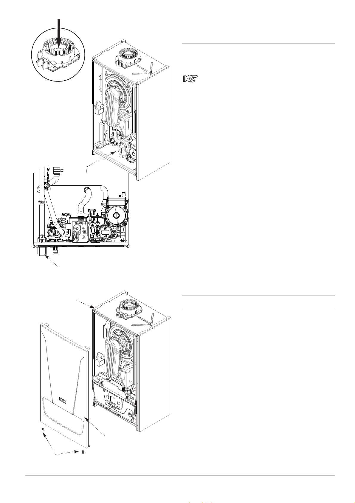
EV1
EV2
P. OUT
1 2 3 4
VENT
ADJ.
Prime Trap by
pouring 300ml of
water into flue spigot
Installation 6
6.2.2 Connecting the Condensate Drain
1. Remove the blanking cap, and using the elbow supplied,
connect the condensate drain pipework to the boiler condensate
trap outlet pipe.
Ensure the discharge of condensate complies with any
national or local regulations in force (see British Gas “Guidance
Notes for the Installation of Domestic Gas Condensing Boilers” &
HHIC recommendations).
Front Panel and
Control Box
removed for clarity
Condensate Trap Connection
(elbow supplied)
2. The elbow will accept 21.5mm (3/4in) plastic overflow pipe
which should generally discharge internally into the household
drainage system. If this is not possible, discharge into an outside
drain is acceptable. See section 5.3.5 for further details.
3. The boiler condensate trap should be primed by pouring
approximately 300ml of water into the flue spigot. Do not allow
any water to fall into the air inlet.
RQRQADJ.
P. OUT
VENT
1 2 3 4
Fig. 23
6.3 Preparation
Locating Lug
Case Front Panel
Securing Screws
6.3.1 Panel Removal
1. Remove the securing screws from the bottom of the case front
panel.
2. Lift the panel slightly to disengage it from the locating lugs on
top of the case and remove it.
Case Front
Panel
7212136 - 02 (08/14) EcoBlue Plus Combi 39
Page 40
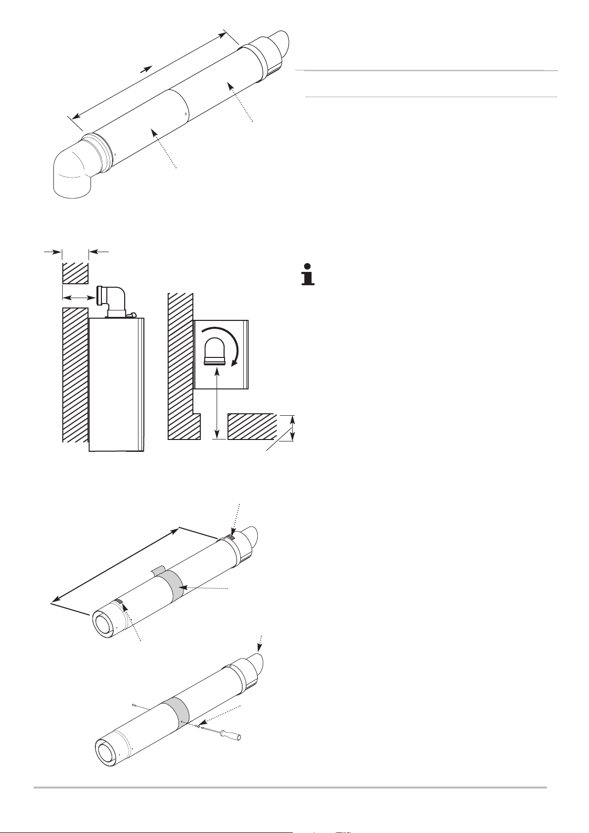
6 Installation
6.4 Air Supply / Flue Gas Connections
Wall Thickness
(X)
315mm 500mm
Connection Assembly
Terminal Assembly
Fig. 24
6.4.1 Connecting the Flue/Chimney
HORIZONTAL TELESCOPIC FLUE (concentric 60/100)
1. There are two telescopic sections, the terminal assembly and
the connection assembly, a roll of sealing tape and two self
tapping screws. A 93° elbow is also supplied.
2. The two sections can be adjusted to provide a length between
315mm and 500mm (Fig. 24) when measured from the flue elbow
(there is 40mm engagement into the elbow).
3. Locate the flue elbow on the adaptor at the top of the boiler.
Set the elbow to the required orientation (Fig. 25).
The flue elbow is angled at 93 degrees to ensure a fall
back to the boiler.
4. Measure the distance from the outside wall face to the elbow.
This dimension will be known as ‘X’ (Fig. 25).
5. If the distance from the flue elbow to the outside face of the
wall (‘X’ in Fig. 25) is less than 250mm the connection assembly
can be discarded and the terminal assembly fitted directly into the
elbow.
Fig. 25
Dimension ‘Y’
Fig. 27
‘TOP’ Label
(X)
Wall
Thickness
‘TOP’ Label
Sealing Tape
‘Peak’ to be
uppermost
6. In instances where the dimension ‘X’ (Fig. 25) is between
250mm and 315mm it will be necessary to shorten the terminal
assembly by careful cutting to accommodate walls of these
thicknesses.
7. To dimension ‘X’ add 40mm. This dimension to be known as
‘Y’.
8. Adjust the two telescopic sections to dimension ‘Y’ and seal the
joint with the tape provided (Fig. 27). Ensure that the labels
marked ‘TOP’ on the terminal and connection assemblies are
uppermost.
9. Using the clearance holes in the connection assembly secure
it to the terminal assembly using the screws supplied with the
telescopic flue (Fig. 28).
Securing Screw
Fig. 28
40 EcoBlue Plus Combi 7212136 - 02 (08/14)
Page 41
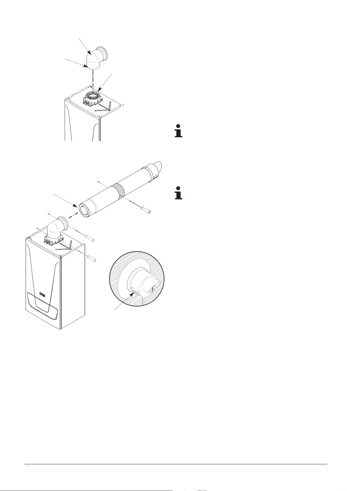
Installation 6
Boiler Elbow
Apply the lubricant
supplied for ease of
assembly (do not
use any other type).
Ensure elbow is
fully engaged into
boiler adaptor
Apply the lubricant
supplied for ease of
assembly (do not use
any other type).
Ensure Flue is fully
engaged into Elbow
Adaptor
Fig. 29
10. Remove the flue elbow and insert the flue through the hole
in the wall. Fit the flue trims if required, and refit the elbow to the
boiler adaptor, ensuring that it is pushed fully in. Secure the
elbow with the screws supplied in the boiler fitting kit (Fig. 29).
11. Draw the flue back through the wall and engage it in the
elbow. It may be necessary to lubricate to ease assembly of the
elbow and flue (Fig. 30).
12. Ensure that the terminal is positioned with the slots to the
bottom (Fig. 31). Secure to the elbow with the screws supplied
with the telescopic flue (Fig. 30).
It is essential that the flue terminal is fitted as shown to
ensure correct boiler operation and prevent water
entering the flue.
13. Make good between the wall and air duct outside the
building, appropriate to the wall construction and fire rating.
14. If necessary fit a terminal guard (see Section 5.3.11).
There must be no part of the air duct (white tube)
visible outside the property.
Fig. 30
Slots at bottom
Fig. 31
7212136 - 02 (08/14) EcoBlue Plus Combi 41
Page 42
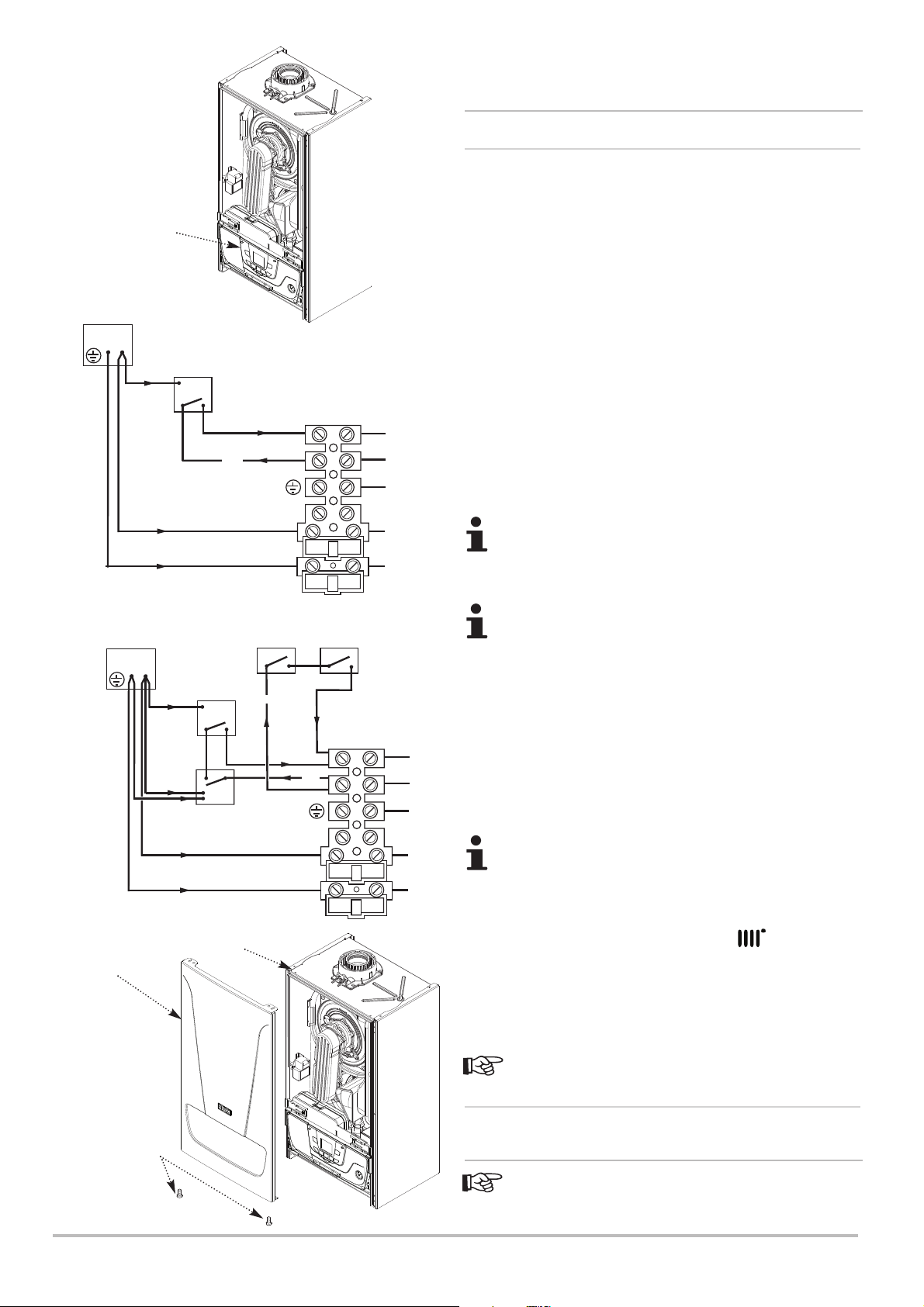
6 Installation
6.5 Electrical Connections
6.5.1 Electrical Connections of the appliance
1. See Section 5.2.2. for details of the electrical supply. Undo the
securing screws and lift the case front panel off.
Fused Spur
Fig. 35
Control Box
L
N
Fused Spur
L
N
Room ‘Stat
N
Room ‘Stat
External Clock
2. Hinge the control box downwards. Disengage the securing tabs
and open the terminal block cover. (Fig. 34).
3. If the mains cable fitted is not long enough slacken the gland
Fig. 34
nut in the right of the boiler lower panel and pass the new mains
cable through it. Remove the grommet adjacent to the gland nut,
pierce the diaphragm and insert the cable from the external
control system.
230V
Terminal M1
230V
N
L
g/y
b
br
b
1
bk
2
4. Leave sufficient slack in the cables to allow the control box to
be hinged fully open. Tighten the gland nut and refit the grommet
and gland nut.
5. Connect the Earth, Permanent Live and Neutral wires to the
terminal strip.
Both the Permanent Live and Neutral connections are
fused.
6. Refer to the instructions supplied with the external control(s).
Any thermostat must be suitable for 230V switching.
Frost Thermostat
Pipe Thermostat
7. Remove the link between connections 1 & 2. The 230V supply
at connection 2 must be connected to the thermostat. The
N
230V
Terminal M1
230V
b
230V
bk
g/y
switched output from the thermostat must be connected to
connection 1. (Figs. 35 & 36). If the room thermostat being used
incorporates an anticipator it MUST be wired as shown in Figs. 35
& 36.
1
2
8. Replace the terminal block cover.
The 230V switched signal for external controls
(Frost Stat - Room Stat - Timer) must always be taken
from terminal 2 at the boiler. Live, Neutral and Earth to
power these controls must be taken from the Fused
Spur. For the Frost Stat to operate the boiler MUST BE
IN CENTRAL HEATING MODE i.e. symbol shown.
9. Engage the front panel onto the locating lugs on top of the
Fig. 36
Case Front
Panel
Locating Lug
N
L
b
br
case & secure with the securing screws at the bottom of the case.
6.5.2 Connecting External Devices
1. See Section 6.7.2. for details of fitting the optional
outdoor sensor accessory.
Case Front Panel
Securing Screws
42 EcoBlue Plus Combi 7212136 - 02 (08/14)
6.6 Filling the Installation
1. See Section 5.2.6 and 5.6.1 for details of flushing and
filling the installation.
Page 43
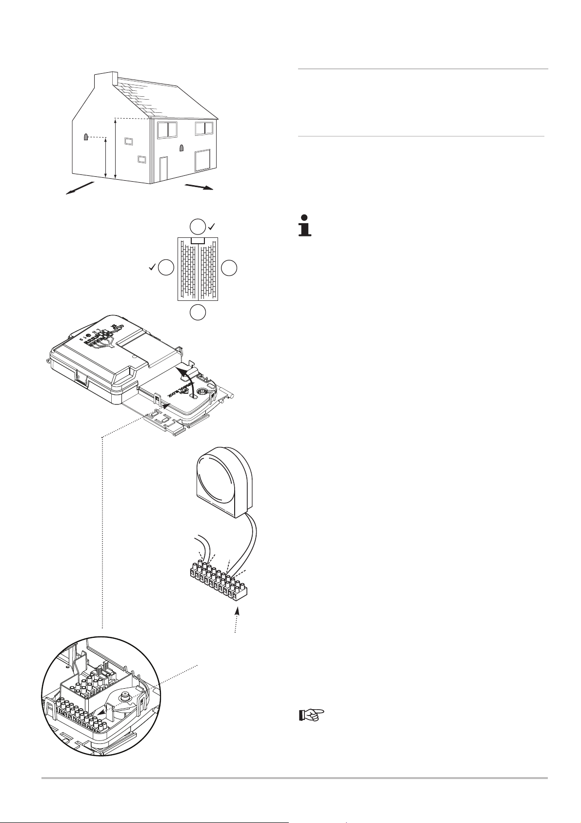
Installation 6
6.7 External Controls6.7 External Controls
6.7.1 Installation of External Sensors
1. Various Sensors are available.
6.7.2 Optional Outdoor Sensor
North
1/2 H
2.5m Min
H
Full instructions are provided with the Outdoor Sensor Kit !
Positioning the Sensor
West
N
1. The sensor must be fixed to an external wall surface of the
property it is serving. The wall must face north or west.
DO NOT position it on a south facing wall in direct
sunlight !
2. The sensor should be approximately half the height of the
WE
X
living space of the property, and a minimum of 2.5m above
ground level.
3. It must be positioned away from any sources of heat or
S
X
cooling (e.g. flue terminal) to ensure accurate operation. Siting
the sensor above doors and windows, adjacent to vents and
close to eaves should be avoided.
Connecting the Sensor
1. Ensure the electrical supply to the boiler is isolated. Undo the
securing screws and lift the case front panel off.
2. Hinge the control box downwards. Disengage the securing
tabs and open the terminal block cover.
From Relay Box
10
10
9
8
7
6
M2 Low Voltage
Terminal Block
3. Remove one of the grommets in the boiler lower panel, pierce
the diaphragm and insert the wires from the outdoor sensor.
4. Leave sufficient slack in the wires to allow the control box to
be hinged fully open. Refit the grommet.
5. Connect the wires from the outdoor sensor to positions 4 & 5
on M2 as shown. Refit the cover.
Setting the Sensor Curve
9
5
4
1. With the outdoor sensor fitted, the boiler central heating flow
temperature is adjusted automatically to accommodate the
change in heat required to optimise the efficient performance of
5
4
3
2
1
the boiler whilst maintaining a comfortable room temperature.
The central heating buttons on the boiler adjust a “simulated
room temperature” used for this optimisation.
2. This functionality requires the setting of three parameters on
the boiler, to suit the heating system and the optimisation can be
adjusted by the user with the central heating control buttons on
the boiler control panel.
Full instructions are provided with the Outdoor Sensor Kit !
Continue with the installation and commissioning of the
boiler as described in this manual.
7212136 - 02 (08/14) EcoBlue Plus Combi 43
Page 44
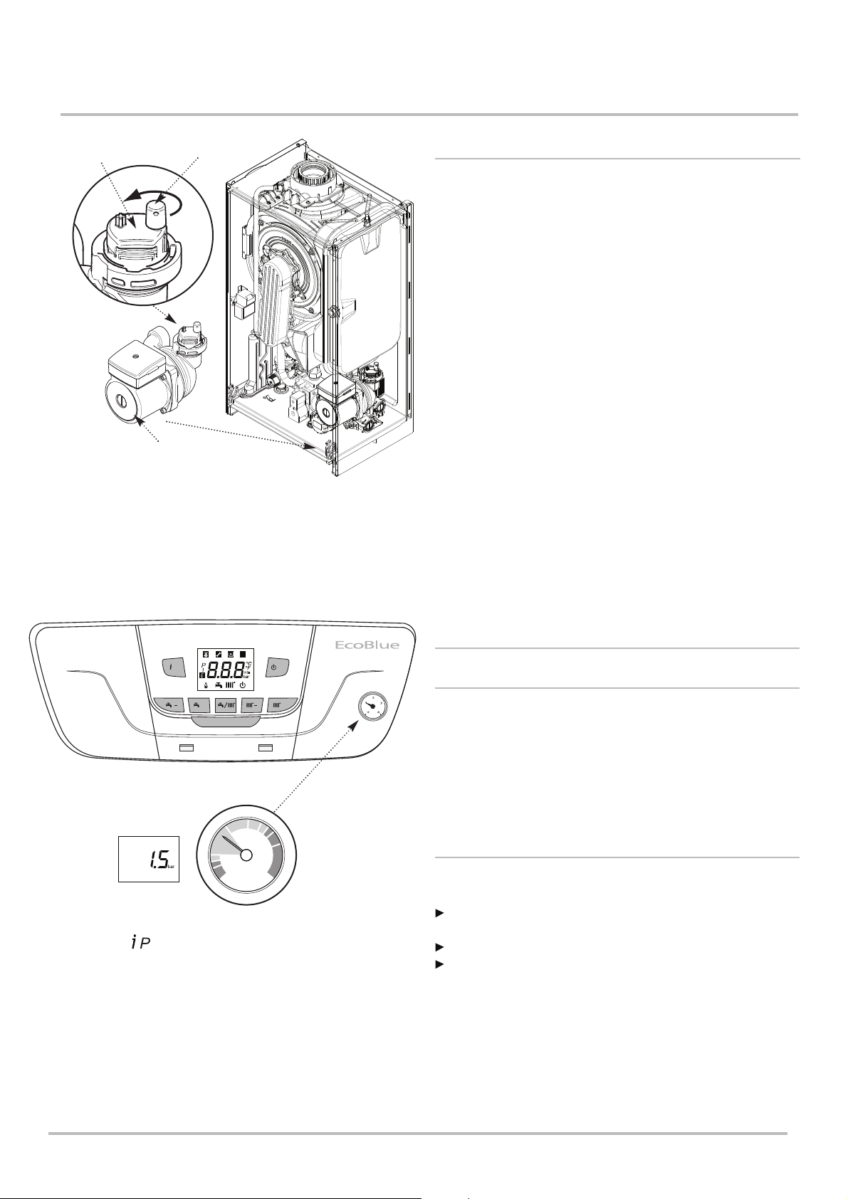
7 Commissioning
bar
0
1
2
3
4
7 Commissioning
Automatic
Air Vent
Fig. 37
Pump
Cap
Control Box
removed for clarity
7.1 General
1. Reference should be made to BS:EN 12828, 12831 & 14336
when commissioning the boiler. Ensure that the condensate
drain trap has been primed - see Section 6.2.2. paragraph 3.
2. At the time of commissioning, complete all relevant sections of
the Benchmark Checklist at the rear of this publication.
3. Open the mains water supply to the boiler and all hot water
taps to purge the DHW system.
4. Ensure that the filling loop is connected and open, then open
the heating flow and return valves on the boiler. Ensure that the
cap on the automatic air vent on the pump body is opened (Fig.
37).
5. The system must be flushed in accordance with BS 7593
(see Section 5.2.6) and the flushing agent manufacturers
instructions.
6. Pressurise the system to 1.5 bar (Fig. 38) then close and
disconnect the filling loop.
/P
Digital pressure reading
which can be accessed
by via the button
and scrolling to setting ‘5’.
Note there may be a
slight difference between
the digital & gauge
reading depending on
boiler operating mode.
R
/R
++
Heating
Pressure Gauge
Fig. 38
7. Test for gas tightness, turn the gas supply on and purge
according to in GB BS 6891 and in IE I.S. 813 "Domestic Gas
Installations".
7.2 Checklist before Commissioning
7.2.1 Preliminary Electrical Checks
1. Prior to commissioning the boiler preliminary electrical system
checks should be carried out.
2. These should be performed using a suitable meter, and
include checks for Earth Continuity, Resistance to Earth, Short
Circuit and Polarity.
7.2.2 Checks
1. Checked:
That the boiler has been installed in accordance with these
instructions.
The integrity of the flue system and the flue seals.
The integrity of the boiler combustion circuit and the relevant
seals.
44 EcoBlue Plus Combi 7212136 - 02 (08/14)
Page 45
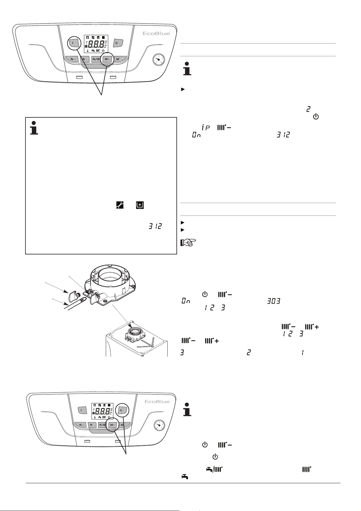
Commissioning 7
/P
These buttons for
Fig. 39
R
/R
++
De-Aeration
FUNCTION INTERRUPTION
• If the De-aeration is interrupted due to a fault the pump will
cease to circulate but the function timer (approx.10 minutes)
will continue to run. For this reason it is recommended to
monitor the boiler display during De-aeration. If the fault
cannot be rectified quickly the function must be restarted to
ensure complete De-aeration.
• In the event of a loss of power the De-aeration function
needs to be restarted once the power is re-established.
• In the event of low water pressure the fault code E118 will
be displayed, along with the flashing and symbols.
This error can be rectified by repressurising the system to at
least 1.0 bar. The pump will restart automatically once the
water pressure is successfully re-established and will
reappear in the display.
• The De-aeration function can be repeated as necessary
until all air is expelled from the system.
Flue Sampling
Point
Plug
7.3 Commissioning Procedure
7.3.1 De-Aeration Function
The display backlight remains lit approx. 10 minutes. If
the backlight goes out during commissioning it does not
mean that the process has been completed.
This procedure MUST be carried out !
1. Ensure the gas is turned Off! Turn the power to the boiler ON.
The software version will be displayed, followed by , then ••
flashing briefly before displaying the ‘Standby’ symbol .
2. Press & together and hold for at least 6 seconds
until is briefly displayed followed by .
3. The De-Aeration Function is now activated. The boiler pump
will run for approx. 10 minutes. During this time the pump will
alternate on and off and the diverter valve will switch between
heating & hot water to purge air from the system.
4. At the end of the process the boiler will return to the ‘Standby’
position.
7.4 Gas Settings
7.4.1 Checking Combustion - ‘Chimney Sweep’ Mode
The case front panel must be fitted when checking combustion.
Ensure the system is cold & the gas supply turned on & purged.
The person carrying out a combustion measurement should
have been assessed as competent in the use of a flue gas analyser
and the interpretation of the results. See Section 10.1.3.
Important: Allow the combustion to stabilise before inserting the
Combustion Analyser Probe into the Test Point. This will prevent
saturation of the analyser.
Analyser Probe
After refitting the sampling
point plug ensure there is no
leakage of products
/P
R
/R
++
These buttons for
‘Chimney Sweep’
1. Press & together and hold for at least 6 seconds.
R
is displayed briefly followed by and the current setting
point (eg. , or ) flashing alternately. Important: There may be a
delay before the boiler fires.
2. To adjust the boiler input setting, press or button
and the current setting point will flash (eg. , or ). Press the
or button again to alter the boiler input setting.
= MAX. HEATING input, = MAX. DHW input, = MIN. input
4. The combustion (CO level & CO/CO
2 ratio) must be measured
and recorded at MAXIMUM DHW input & MINIMUM input.
5. Follow the flow chart on the next page to comply with the
requirement to check combustion on commissioning.
The system MUST be cold to ensure the boiler is operating
under full demand. To obtain an accurate measurement on
smaller capacity systems it may be necessary to open one
or more hot taps and remove the diverter valve motor (see
Section 10.3.20) in order to maintain the boiler output.
6. Press & again for at least 6 seconds to exit.
7. Press the once to bring the boiler out of ‘Standby’ mode.
R
R
8. Use the button to toggle through the CH and DHW
settings to activate the required modes.
7212136 - 02 (08/14) EcoBlue Plus Combi 45
Page 46
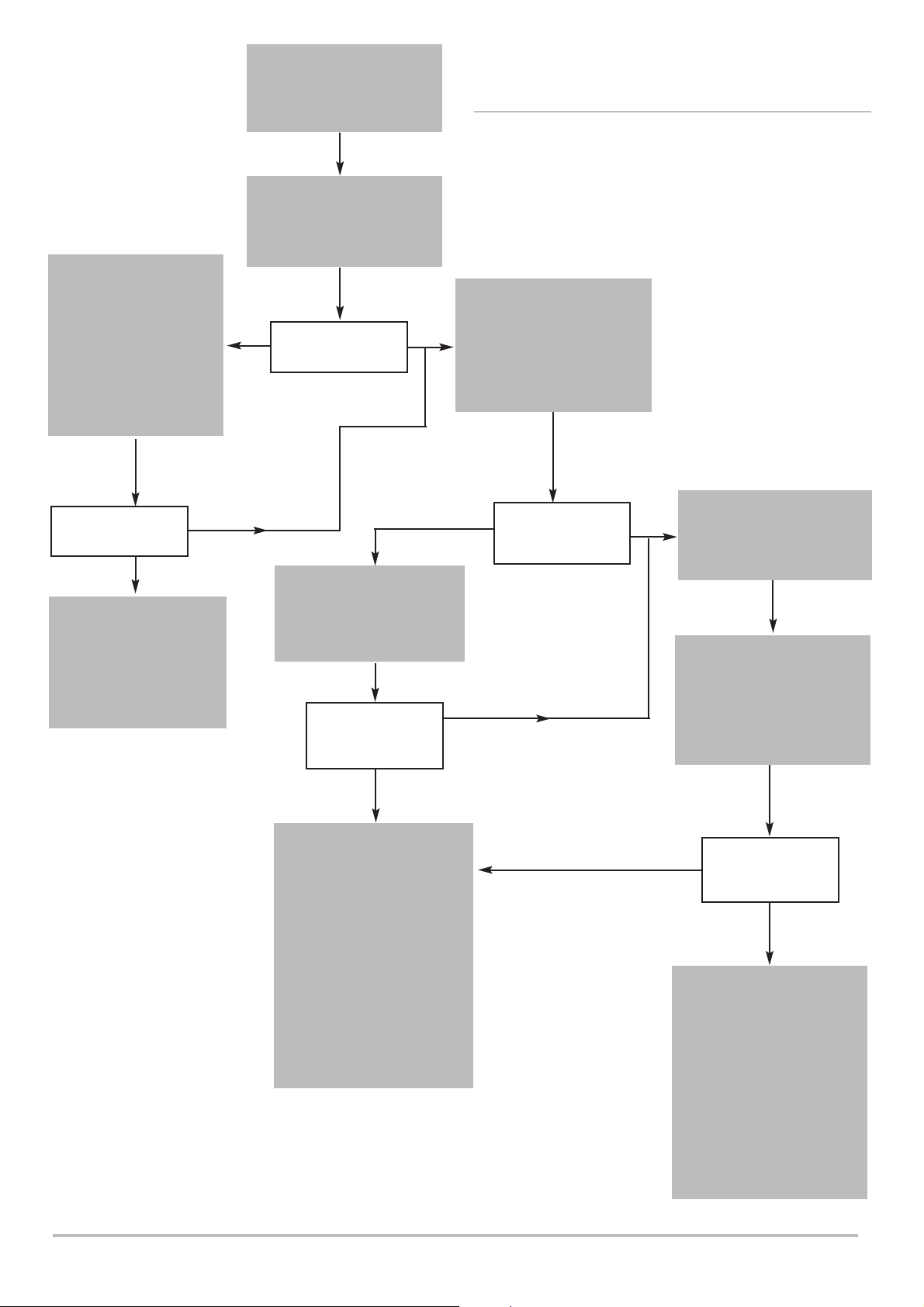
7 Commissioning
Verify Flue Integrity
Indication that products of
combustion & inlet air are
mixing - further
investigation is required.
Check all flue components
are correctly assembled,
fixed & supported. Check
the flue & terminal are
unobstructed.
Set Boiler to Maximum Rate
(see 7.4.1)
Allow the combustion to
stabilise. Do not insert probe
to avoid ‘flooding’ the analyser.
Perform Flue Integrity
Combustion Check
Insert the analyser probe into
the air inlet test point, allowing
the reading to stabilise.
No
Is O
2 20.6% and
CO
2 < 0.2% ?
7.4.1 Checking Combustion (cont)
9. Follow the flow chart opposite.
Check CO & Combustion
Ratio at Maximum Rate
Whilst the boiler is still
Yes
operating at maximum insert
the analyser probe into the
flue gas test point, allowing
the reading to stabilise.
Is O
2 20.6% and
CO
2 < 0.2% ?
No
TURN APPLIANCE OFF !
Call 0844 871 1555 for
advice.
The appliance MUST NOT
be commissioned until all
problems are identified
and resolved.
Yes
Verify Integrity of Seals
Check all burner seals,
internal flue seals, door &
case seals. Replace any
seals that appear unsound.
Is CO < 350ppm
and CO/CO
2 ratio
< 0.004 ?
No
TURN APPLIANCE OFF !
Call 0844 871 1555 for advice.
The appliance MUST NOT be
commissioned until all
problems are identified and
resolved.
If commissioning cannot be
fully completed the appliance
must be disconnected from the
gas supply in accordance with
the GSIUR.
Note: Check & record the CO
& combustion ratio at both
maximum & minimum rates
before calling 0844 871 1555.
No
Is CO < 350ppm
and CO/CO
2 ratio
< 0.004 ?
Yes
No
Set Boiler to Minimum Rate
(see 7.4.1)
Yes
Allow the combustion to
stabilise. Do not insert probe
to avoid ‘flooding’ the analyser.
Check CO & Combustion
Ratio at Minimum Rate
Whilst the boiler is
operating at minimum insert
the analyser probe into the
flue gas test point, allowing
the reading to stabilise.
Is CO < 350ppm
and CO/CO
< 0.004 ?
Yes
BOILER OPERATING
SATISFACTORILY. NO
FURTHER ACTION
REQUIRED
Ensure test points are capped,
the boiler case front panel is
correctly fitted & secured and
all other commissioning
procedures completed.
Complete the ‘Benchmark’
Checklist, recording the CO &
combustion ratio readings as
required.
2 ratio
46 EcoBlue Plus Combi 7212136 - 02 (08/14)
Page 47
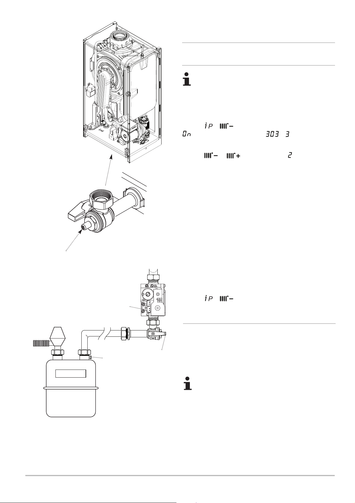
Control Box removed
for clarity
Commissioning 7
7.5 Configuring the System
7.5.1 Check the Operational (Working Gas Inlet
Pressure & Gas Rate)
The system MUST be cold to ensure the boiler is
operating under full demand. To obtain an accurate
measurement on smaller capacity systems it may be
necessary to open one or more hot taps and remove
the diverter valve motor (see Section 10.3.20) in order
to maintain the boiler output.
1. Press & together and hold for at least 6 seconds.
is displayed briefly followed by & flashing
alternately. ‘3’ represents MAXIMUM HEATING input.
2. Press or to adjust the input. represents
MAXIMUM DHW input.
3. With the boiler operating in the maximum rate condition
check that the operational (working) gas pressure at the inlet
gas pressure test point is in accordance with B.S. 6798 & B.S.
6891. This must be AT LEAST 17mb !
Gas Cock Inlet
Pressure Test Point
Fig. 41
Gas Meter
Gas Valve
17-21 mbar
Gas Cock
19-23 mbar
RQ
ADJ.
P. OUT
VENT
EV2
1 2 3 4
EV1
18-22 mbar
4. Ensure that this inlet pressure can be obtained with all other
gas appliances in the property working. The pressure should be
measured at the test point on the gas cock (Fig. 41).
Measure the Gas Rate
5. With any other appliances & pilot lights turned OFF the gas
rate can be measured. It should be:-
Natural Gas 24 model 2.61 m
28 model 3.05 m
33 model 3.59 m
3
/h
3
/h
3
/h
6. Press & together and hold for at least 6 seconds
to exit the function.
7.6 Final Instructions
7.6.1 Handover
1. Carefully read and complete all sections of the Benchmark
Commissioning Checklist at the rear of this publication that are
relevant to the boiler and installation. These details will be
required in the event of any warranty work.
The warranty will be invalidated if the Benchmark
section is incomplete.
Fig. 41a
2. The publication must be handed to the user for safe keeping
and each subsequent regular service visit recorded.
3. Hand over the User’s Operating, Installation and Servicing
Working Gas Pressures
Instructions, giving advice on the necessity of regular servicing.
If the pressure drops are greater than shown in
Fig. 41a (above) a problem with the pipework or
connections is indicated.
4 . For IE, it is necessary to complete a “Declaration of
Conformity” to indicate compliance with I.S. 813. An example of
this is given in I.S. 813 “Domestic Gas Installations”. This is in
addition to the Benchmark Commissioning Checklist.
7212136 - 02 (08/14) EcoBlue Plus Combi 47
Page 48
7 Commissioning
5. Set the central heating and hot water temperatures to the
requirements of the user. Instruct the user in the operation of
the boiler and system.
Information Display
The button can be pressed so that the display shows
the following information:-
‘00’ alternates with Sub-Code (only when fault on boiler) or ‘000’
‘01’ alternates with CH Flow Temperature
‘02’ alternates with Outside Temperature (where Sensor fitted)
‘03’ alternates with DHW Temperature
‘04’ alternates with DHW Temperature
‘05’ alternates with System Water Pressure
‘06’ alternates with CH Return Temperature
‘07’ alternates with Flue Temperature
‘08’ - not used
‘10’ alternates with Zone 1 CH Flow Temperature
‘11’ alternates with Zone 2 CH Flow Temperature
‘12’ alternates with Ion current
‘13’ alternates with Burner working hours
‘14’ alternates with Zone 1 CH mode
‘15’ alternates with Zone 2 CH mode
‘16’ alternates with DHW circuit operating mode
‘17’ alternates with Boiler operating mode
‘18’ alternates with Solar plant operating mode
‘19’ alternates with Manufacturer information
‘20’ alternates with Manufacturer information
Depending upon boiler model and any system controls
connected to the appliance, not all information codes will be
displayed and some that are will not have a value.
Press to return to the normal display.
R
6. Instruct the user in the operation of the boiler controls.
7. Demonstrate to the user the action required if a gas leak
occurs or is suspected. Show them how to turn off the gas
supply at the meter control, and advise them not to operate
electric light or power switched, and to ventilate the property.
8. Show the user the location of the system control isolation
switch, and demonstrate its operation.
9. Advise the user that they may observe a plume of vapour
from the flue terminal, and that it is part of the normal operation
of the boiler.
7.6.2 System Draining
1. If at any time after installation it is necessary to drain & refill
the central heating system (e.g. when replacing a radiator) the
De-Aeration Function should be activated.
Re-pressurise the system to 1.5 bar
2. On refilling the system ensure that there is no heating or hot
water demand, but that there is power to the boiler. It is also
recommended that the gas supply is turned off to prevent
inadvertent ignition of the burner.
3. Press & together and hold for at least 6 seconds.
The ‘De-Aeration’ Function will be activated.
4. The boiler pump will run for up to 10 minutes during which
time the diverter valve will switch between heating & hot water.
This will purge air from the system. The display will show .
5. Once De-Aeration is complete recommission the appliance
and check that the inhibitor concentration is sufficient.
See Section 7.3.1 for more detail.
48 EcoBlue Plus Combi 7212136 - 02 (08/14)
Page 49

8 Operation
Operation 8
8.1 General
1. It is the responsibility of the installer to instruct the user in the
day to day operation of the boiler and controls and to hand over
the completed Benchmark Checklist at the back of this manual.
2. Set the central heating and hot water temperatures to the
requirements of the user. Instruct the user in the operation of the
boiler and system.
3. The temperature on the boiler must be set to a higher
temperature than the cylinder thermostat to achieve the required
hot water demand.
4. Instruct the user in the operation of the boiler and system
controls.
5. Demonstrate to the user the action required if a gas leak
occurs or is suspected. Show them how to turn off the gas
supply at the meter control, and advise them not to operate
electric light or power switched, and to ventilate the property.
6. Show the user the location of the system control isolation
switch, and demonstrate its operation.
7. Advise the user that they may observe a plume of vapour from
the flue terminal, and that it is part of the normal operation of the
boiler.
8. The method of repressurising the primary system should be
demonstrated.
9. If at any time after installation it is necessary to drain & refill
the central heating system (e.g. when replacing a radiator) the
De-Aeration Function should be activated (see 7.6.2).
8.2 To Start-up
Switch on the boiler at the fused spur unit and ensure that the
time control is in the on position and any other controls (e.g.
room thermostat) are calling for heat.
Press the once to bring the boiler out of Standby mode.
The boiler will begin its start sequence.
R
8.3 To Shutdown
Isolate the mains power supply at the fused spur unit.
Isolate the gas supply at the boiler valve.
7212136 - 02 (08/14) EcoBlue Plus Combi 49
Page 50
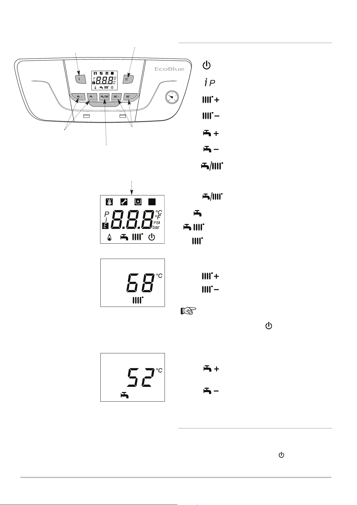
8 Operation
Boiler Information
View
/P
Domestic Hot Water
Temperature Adjustment
Standby - Reset - Esc
R
/R
++
Central Heating
Temperature Adjustment
Summer - Winter -
Heating Only Mode
Display Screen
8.4 Use of the Control Panel
Key to Controls
Standby - Reset - Esc Button
R
Boiler Information View Button
Increase CH Temperature Button
Decrease CH Temperature Button
Increase DHW Temperature Button
Decrease DHW Temperature Button
Summer / Winter / Only Heating Mode Button
Summer - Winter - Heating Only Mode
1. Press button until the required mode appears:-
R
Summer - DHW only mode
Winter - DHW & CH mode
Heating Only - Only CH mode
R
To increase or decrease the boiler temperature
1. Press to increase the Central Heating temperature.
2. Press to decrease the Central Heating temperature.
An overheat thermostat (NTC) is positioned in the heat
exchanger which shuts down the appliance if the boiler
temperature exceeds 100°C. Press button to
R
re-establish normal operating conditions.
To adjust the domestic hot water temperature
R
1. Press to increase the Domestic Hot Water
temperature.
2. Press to decrease the Domestic Hot Water
temperature.
8.5 Frost Protection
1. The boiler incorporates an integral frost protection feature
that will operate in both Central Heating and Domestic Hot
Water modes, and also when in standby ( displayed) see
section 4.2.3 Boiler Frost Protection Mode.
50 EcoBlue Plus Combi 7212136 - 02 (08/14)
Page 51

9 Settings
Settings 9
9.1 Parameters
The operating parameters of the boiler have been factory set to
suit most systems.
7212136 - 02 (08/14) EcoBlue Plus Combi 51
Page 52
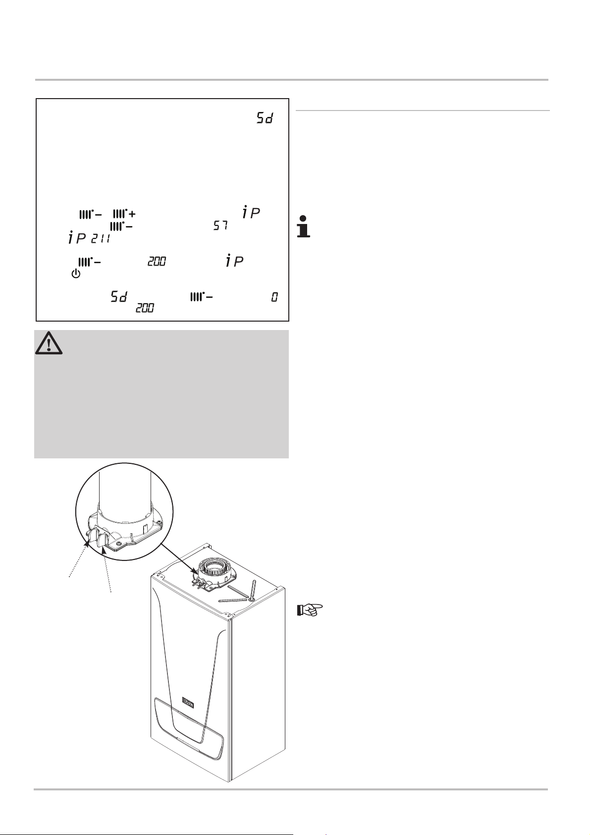
10 Maintenance
10 Maintenance
‘Service Due’ Message
After 11 months operation the ‘Service Due’ message
will be shown on the boiler display. (If the installation has
been subject to prolonged electrical isolation or power cuts
this period may be longer than 11 months) Once the service
has been completed satisfactorily the ‘Service Due’
message can be reset or de-activated.
To Reset or Disable
1. Press & for 6 seconds then press for 6
seconds. Using scroll through until is displayed.
Press , or higher will be displayed.
2. Press to scroll to . Confirm with then
press to return the display to normal.
3. To disable the function keep pressed until
is displayed instead of .
R
WARNING
When changing components ensure that both the
gas and electrical supplies to the boiler are isolated
before any work is started. When the component has
been changed recommission the boiler as described
in Section 7.
Always examine any seals or gaskets, replacing
where necessary. The Case Front Panel MUST seal
effectively against the boiler side panels.
10.1 General
1. For reasons of safety and economy, it is recommended that
the boiler is serviced annually. Servicing must be performed by a
competent person in accordance with B.S. 7967-4.
2. After servicing, complete the relevant Service Interval Record
section of the Benchmark Commissioning Checklist at the rear of
this publication.
During routine servicing, and after any maintenance or
change of part of the combustion circuit, the following
must be checked:-
• The integrity of the complete flue system and the flue seals
by checking air inlet sample to eliminate the possibility of
recirculation. O2 20.6% & CO2< 0.2%
• The integrity of the boiler combustion circuit and relevant
seals.
• The operational gas inlet pressure and the gas rate as
described in Section 7.5.1.
• The combustion performance as described in ‘Check the
Combustion Performance’ below.
3. Competence to carry out Checking Combustion
Performance B.S. 6798 ‘Specification for Installation &
Maintenance of Gas Fired Boilers not exceeding KWh’ advises
that:-
• The person carrying out a combustion measurement should
have been assessed as competent in the use of a flue gas
analyser and the interpretation of the results.
Flue Sampling
Point
After refitting the sampling
point plug ensure there is no
leakage of products
Air Sampling
Point
• The flue gas analyser used should be one meeting the
requirements of BS7927 or BS-EN50379-3 and be calibrated
in accordance with the analyser manufacturers’ requirements.
• Competence can be demonstrated by satisfactory completion
of the CPA1 ACS assessment, which covers the use of
electronic portable combustion gas analysers in accordance
with BS 7967, Parts 1 to 4.
4. Check the Combustion Performance (CO/CO2ratio)
Set the boiler to operate at maximum rate as described
in Section 7.4.
5. Remove the plug from the flue sampling point, insert the
analyser probe and obtain the CO/CO2ratio. This must be less
than 0.004. If the combustion reading (CO/CO2 ratio) is greater
than this, and the integrity of the complete flue system and
combustion circuit seals has been verified, and the inlet gas
pressure and gas rate are satisfactory either:-
• Perform the ‘Standard Inspection and Maintenance’ (Section
10.2) & re-check.
• Perform ‘Setting the Gas Valve’ (Section 10.3.25) & re-check.
• Replace and set the gas valve (Sections 10.3.24 & 25) &
re-check.
52 EcoBlue Plus Combi 7212136 - 02 (08/14)
Page 53
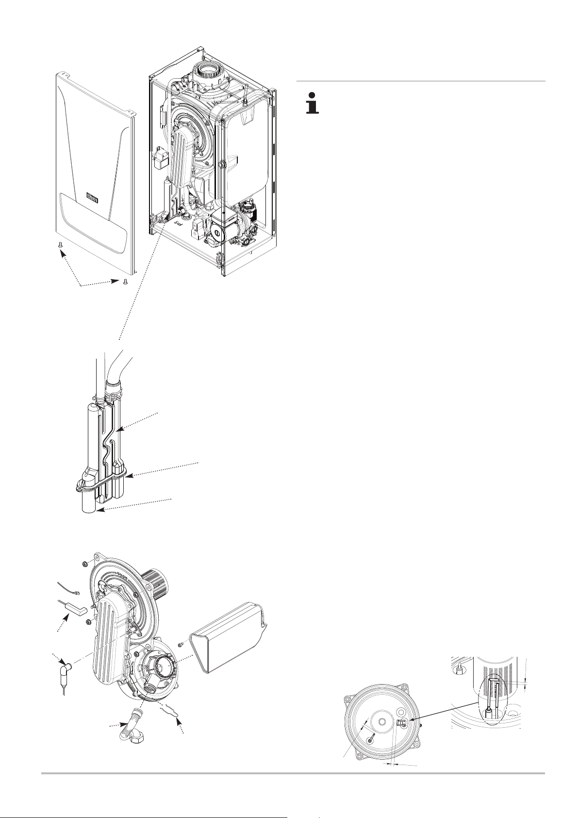
Maintenance 10
10.2 Standard Inspection and Maintenance
Operation
When performing any inspection or maintenance
personal protective equipment must be used where
appropriate.
1. Ensure that the boiler is cool and that both the gas and
electrical supplies to the boiler are isolated.
2. Remove the screws securing the case front panel. Lift the
panel slightly to disengage it from the tabs on top of the case
(Fig. 43). Hinge down the control box.
3. To aid access disconnect the igniter plug & disconnect the
two pipes from the top of the condensate trap and the drain pipe
from the trap outlet. Undo the screw & washer securing the trap
to the boiler lower panel.
Case Front Panel
Securing Screws
Condensate Trap
Condensate Drain
Pipe Connection
Fan, Collector and
Cover Assembly
Control Box
removed for clarity
Gasket
4. Disengage the lip on the trap from the slotted bracket and
remove the trap. Take care not to spill any residual condensate
on the controls and P.C.B. Thoroughly rinse the trap and
examine the gasket on the trap base, replacing if necessary.
5. Remove the clip securing the gas feed pipe to the air/gas
venturi. Disconnect the pipe. Do not break the joint between the
pipe and gas valve unless necessary.
6. Note their position and disconnect the electrode leads and
the fan electrical plugs (Fig. 46).
7. Undo the four 10mm nuts retaining the combustion box cover
to the heat exchanger.
8. Carefully draw the fan, collector and cover assembly forward
(Fig. 46).
9. Clean any debris from the heat exchanger and check that the
gaps between the coils are clear.
10. Inspect the burner, electrodes position (Fig. 45) and
insulation, cleaning or replacing if necessary. Clean any dirt or
dust from the boiler.
11. Carefully examine all seals, insulation & gaskets, replacing
as necessary. Look for any evidence of leaks or corrosion, and
if found determine & rectify the cause.
12. Prime the trap and reconnect the pipes to the top.
Electrode
Reassemble in reverse order.
Leads
Air Box
Electrode
Position
Fig. 46
Gas Feed
Pipe
7212136 - 02 (08/14) EcoBlue Plus Combi 53
Securing Clip
Fig. 45
Flame
Sensing
Electrode
1
±
7.5
1
0
±
1
Spark Ignition
Electrode
0.5
±
4
Page 54
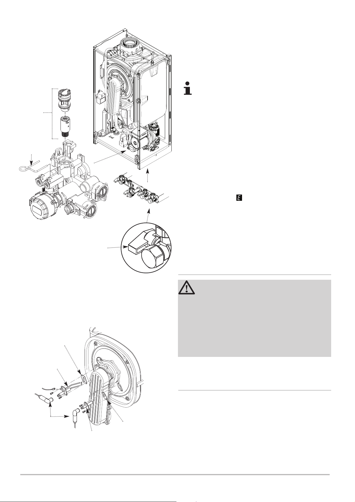
10 Maintenance
Control Box
removed for clarity
Flow
Restrictor
Expansion Vessel Charge - 1.0 bar
13. To check the charge accurately ensure the system is cold.
It is also necessary to relieve the pressure by draining the
boiler. Using a suitable gauge check the pressure at the valve
on the underside of the vessel. Adjust the pressure as required
and repressurise the system.
A right angled valve extension will aid checking and
repressurising.
Filter
Cartridge
Clip
Fig. 48
Turbine
& Filter
Inlet/Return Manifold
DHW
Isolation Cock
Fig. 47
View
underneath
appliance
DHW Filter (Fig. 48)
14. If the flow of domestic hot water is diminished, it may be
necessary to clean the filter.
15. Turn the cold mains isolation cock (Fig. 47) off and draw off
from a hot tap.
16. Disconnect the pump cable, remove the retaining clip and
extract the filter cartridge and rinse thoroughly in clean water.
Reassemble and check the flow.
17. Check the operation of the Safety Pressure Relief Valve.
Simulate ‘Flame Failure’ fault by isolating the supply at gas cock
and operating the boiler. 133 should be displayed.
18. Reassemble the appliance in reverse order, ensuring the
front case panel is securely fitted. Recommission the boiler.
19. Complete the relevant Service Interval Record section of the
Benchmark Commissioning Checklist at the rear of this
publication and then hand it back to the user.
10.3 Specific Maintenance Operations
Changing Components
Sealing
Gasket
Spark Ignition
Electrode
Electrode
Leads
Fig. 49
Flame Sensing
Electrode
Sealing
Gasket
WARNING
When changing components ensure that both the
gas and electrical supplies to the boiler are isolated
before any work is started. When the component has
been changed recommission the boiler as described
in Section 7.
Always examine any seals or gaskets, replacing
where necessary. The Case Front Panel MUST seal
effectively against the boiler side panels.
See Section 10.2 paragraph 2 for removal of case panel door
etc.
10.3.1 Spark Ignition & Flame Sensing Electrodes
1. Note their position and disconnect the electrode leads.
Remove the retaining screws securing each of the electrodes to
the combustion box cover and remove the electrodes, noting
their orientation.
2. Check the condition of the sealing gaskets and replace if
necessary. Reassemble in reverse order (Fig. 49).
3. If satisfactory combustion readings are not obtained ensure
the electrode position is correct and perform the combustion
check again.
54 EcoBlue Plus Combi 7212136 - 02 (08/14)
Page 55
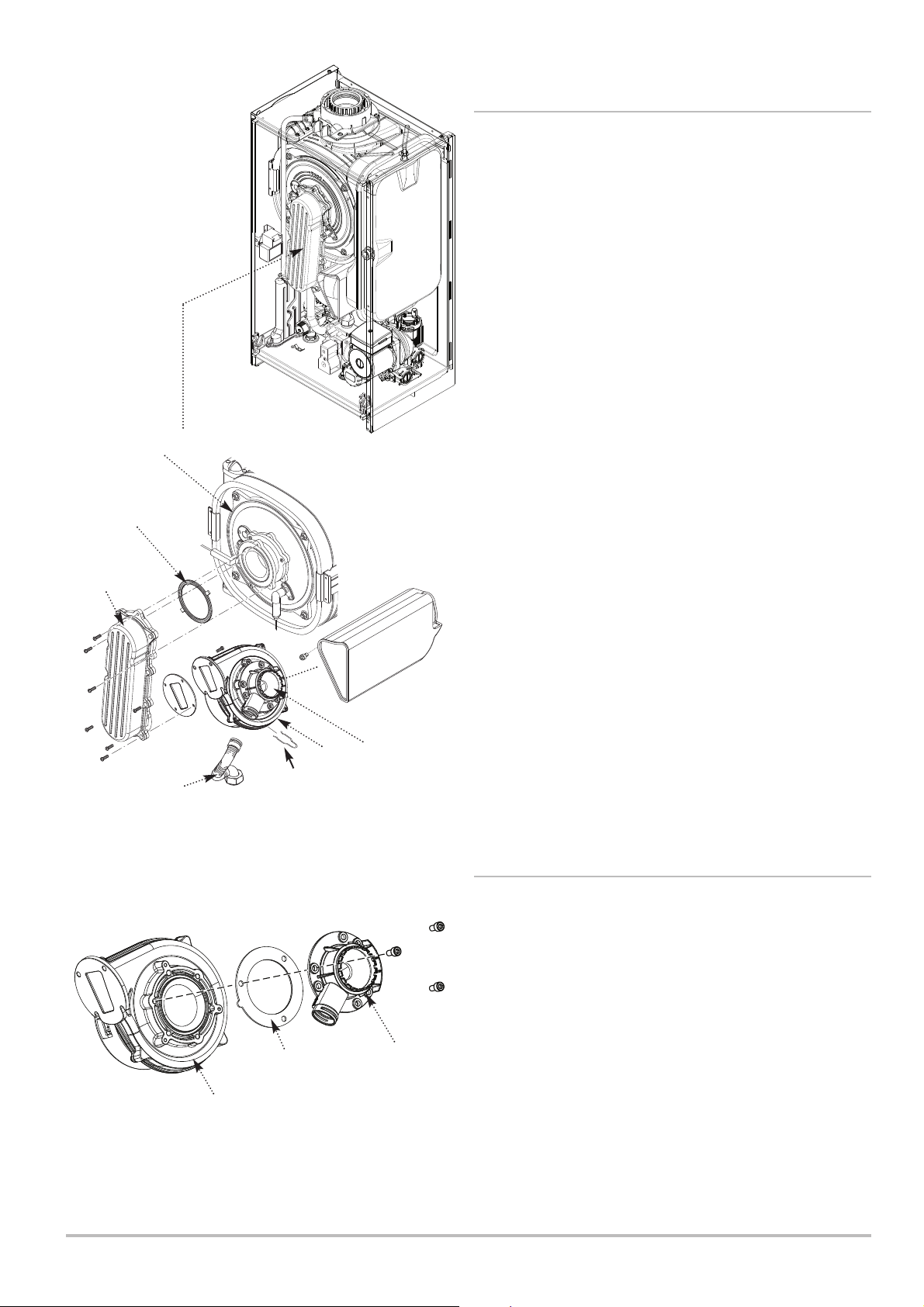
Maintenance 10
10.3.2 Fan (Figs. 50 & 51)
1. Remove the clip securing the gas feed pipe to the air/gas
venturi. Disconnect the pipe.
2. Undo the screws securing the air/gas collector to the
extension piece and disconnect the fan electrical plugs (Fig. 50).
3. Remove the collector and fan assembly, being careful to retain
the gasket.
4. Undo the securing screw and remove the airbox, disengaging
it from the fan venturi. Undo the screws securing the fan to the
collector. Retain the gasket.
5. Undo the screws securing the venturi to the fan (noting its
position) and transfer to the new fan, replacing the seal if
necessary. Examine the gasket(s) and replace if necessary.
Gasket
Air/Gas
Collector
Gas Feed
Cover
Pipe
Clip
Control Box
removed for clarity
Fan
Air/Gas
Venturi
Fig. 50
Air Box
10.3.3 Air/Gas Venturi (Figs. 50 & 51)
1. Undo the securing screw and remove the airbox, disengaging
it from the fan venturi. Remove the clip securing the gas feed
pipe to the venturi.
2. Undo the screws securing the collector to the extension piece
and disconnect the fan electrical plugs.
3. Remove the collector and fan assembly, being careful to retain
the gasket.
Seal
Venturi
4. Undo the screws securing the venturi to the fan (noting its
Fan
Fig. 51
position) and fit the new venturi, replacing the seal if necessary.
Examine the gasket and replace if necessary.
5. After changing the venturi check the combustion - see Section
7.4.1.
7212136 - 02 (08/14) EcoBlue Plus Combi 55
Page 56
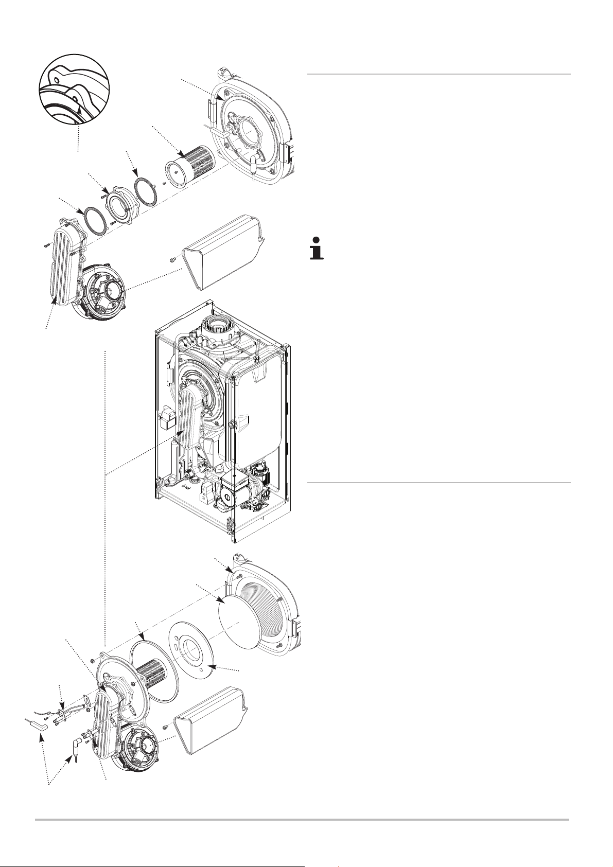
10 Maintenance
Extension Piece
(note orientation)
Burner
Gasket
Burner
10.3.4 Burner
Cover
1. Undo the securing screw and remove the airbox, disengaging
it from the fan venturi. Remove the clip securing the gas feed
pipe to the air/gas venturi and disconnect the fan electrical plugs.
2. Undo the screws securing the air/gas collector to the
extension piece. Note its orientation and remove the extension
piece (where fitted) from the cover.
Gasket
Air/Gas
Collector
3. Undo the screws securing the burner. Withdraw the burner
from the cover and replace with the new one.
4. Examine the gasket(s), replacing if necessary.
Note that the gaskets are not the same !
5. After changing the burner check the combustion.
Air Box
Fig. 52
10.3.5 Insulation (Fig. 53)
Air/Gas
Collector
Spark
Ignition
Electrode
Electrode
Leads
Control Box
removed for clarity
Seal
Flame
Sensing
Electrode
Exchanger
Rear
Insulation
Fig. 53
Heat
Cover
Insulation
Air Box
1. Undo the securing screw and remove the airbox, disengaging
it from the fan venturi. Remove the clip securing the gas feed
pipe to the air/gas venturi and disconnect the fan electrical plugs.
2. Remove the electrodes as described in section 13.1.
3. Undo the nuts holding the cover to the heat exchanger. Draw
the air/gas collector, fan and cover assembly away.
4. Remove the cover insulation piece.
5. Fit the new insulation carefully over the burner and align it with
the slots for the electrodes.
6. If the rear insulation requires replacement, remove it and all
debris from the heat exchanger. Also it may be necessary to
separately remove the spring clip from the pin in the centre of
the heat exchanger and the ‘L’ shaped clips embedded in the
insulation.
7. Do not remove the shrink-wrapped coating from the
replacement rear insulation. Keep the insulation vertical and
press firmly into position.
8. Examine the cover seal and replace if necessary. Reassemble
in reverse order.
56 EcoBlue Plus Combi 7212136 - 02 (08/14)
Page 57
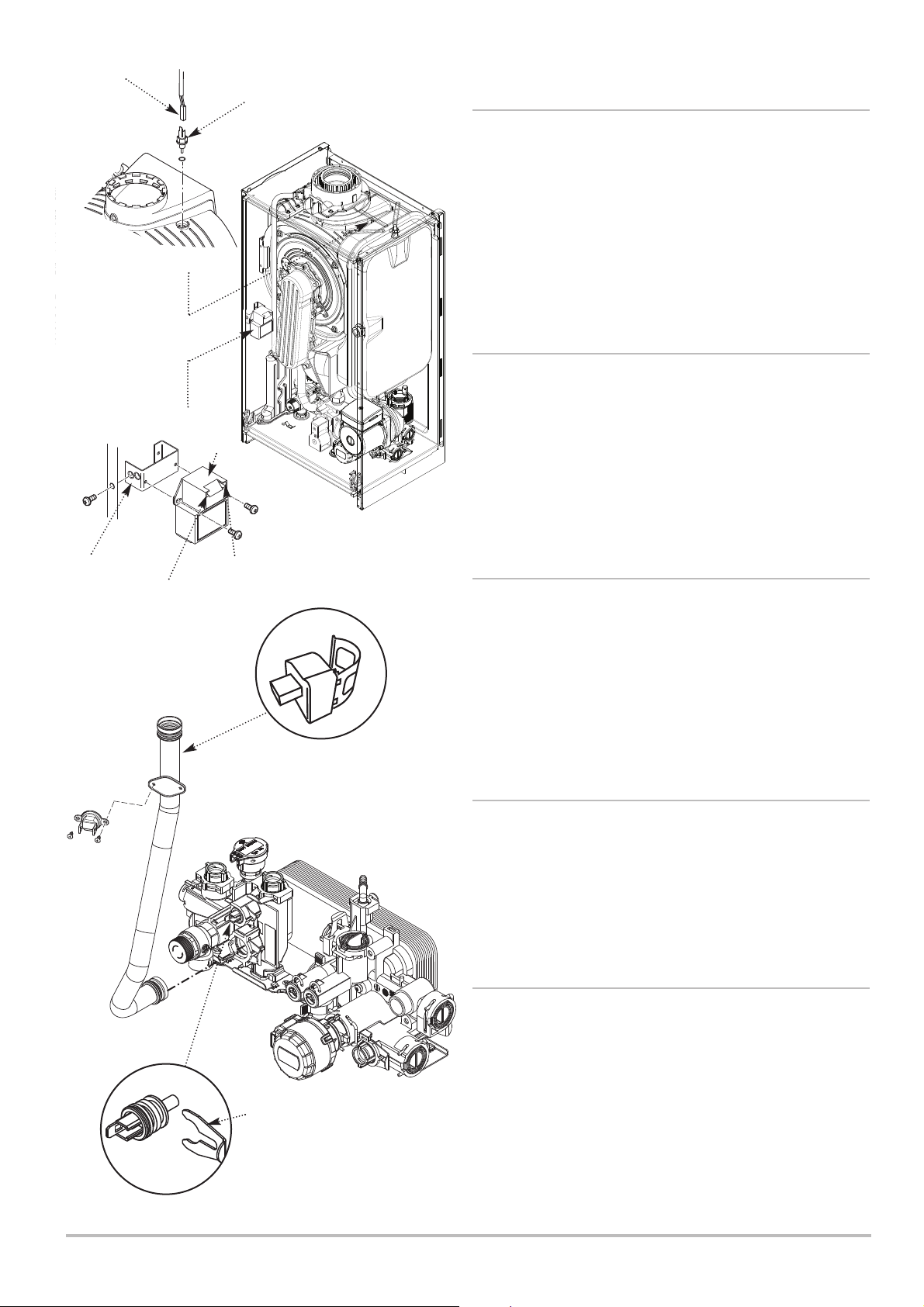
Electrical
Plug
Fig. 54
Flue Sensor
Maintenance
10
10.3.6 Flue Sensor
1. For ease of access remove the Expansion Vessel as
described in Section 10.3.23.
2. Ease the retaining tab on the sensor away and disconnect the
electrical plug.
3. Turn the sensor 90° anticlockwise to remove - it is a bayonet
connection.
4. Reassemble in reverse order.
10.3.7 Igniter (Fig. 54)
1. Note the position of the ignition & sensing leads and
disconnect them. Also disconnect the igniter feed plug.
Mounting
Bracket
Safety
Thermostat
Spark
Connection (‘A’)
Igniter
Earth
Connection (‘B’)
Control Box
removed for clarity
Heating Flow
Sensor
2. Undo the screw securing the igniter mounting bracket to the
left hand side panel. Remove the igniter and bracket and
transfer the bracket to the new igniter.
3. Reassemble in reverse order, reconnecting the plug and
leads to the igniter.
10.3.8 Heating Flow & Return Sensors (Fig. 55)
1. There is one sensor on the flow (red wires) and one sensor
on the return (blue wires). Note: For access to the return sensor
first remove the fan and air/gas collector (see 10.3.2).
2. After noting the position prise the sensor clip off the pipe and
disconnect the plug.
3. Connect the plug to the new sensor and ease the clip onto
the pipe as close to the heat exchanger as possible.
10.3.9 Safety Thermostat (Fig. 55)
1. Pull the two spade connections off the safety thermostat.
2. Remove the screws securing the thermostat to the mounting
plate on the flow pipe.
3. Reassemble in reverse order, ensuring that the connections
are pushed fully on.
10.3.10 DHW NTC Sensor (Fig. 56)
Fig. 55
1. Turn off the mains cold water supply tap and draw off the
residual domestic hot water.
2. Ease the retaining tab on the sensor away and disconnect the
electrical plug.
Retaining
Clip
Fig. 56
DHW NTC Sensor
7212136 - 02 (08/14) EcoBlue Plus Combi 57
3. Remove the retaining clip and withdraw the sensor from the
hydraulic outlet assembly. Examine the ‘O’ ring, replacing if
necessary.
4. Reassemble in reverse order. The plug will only fit one way.
Page 58
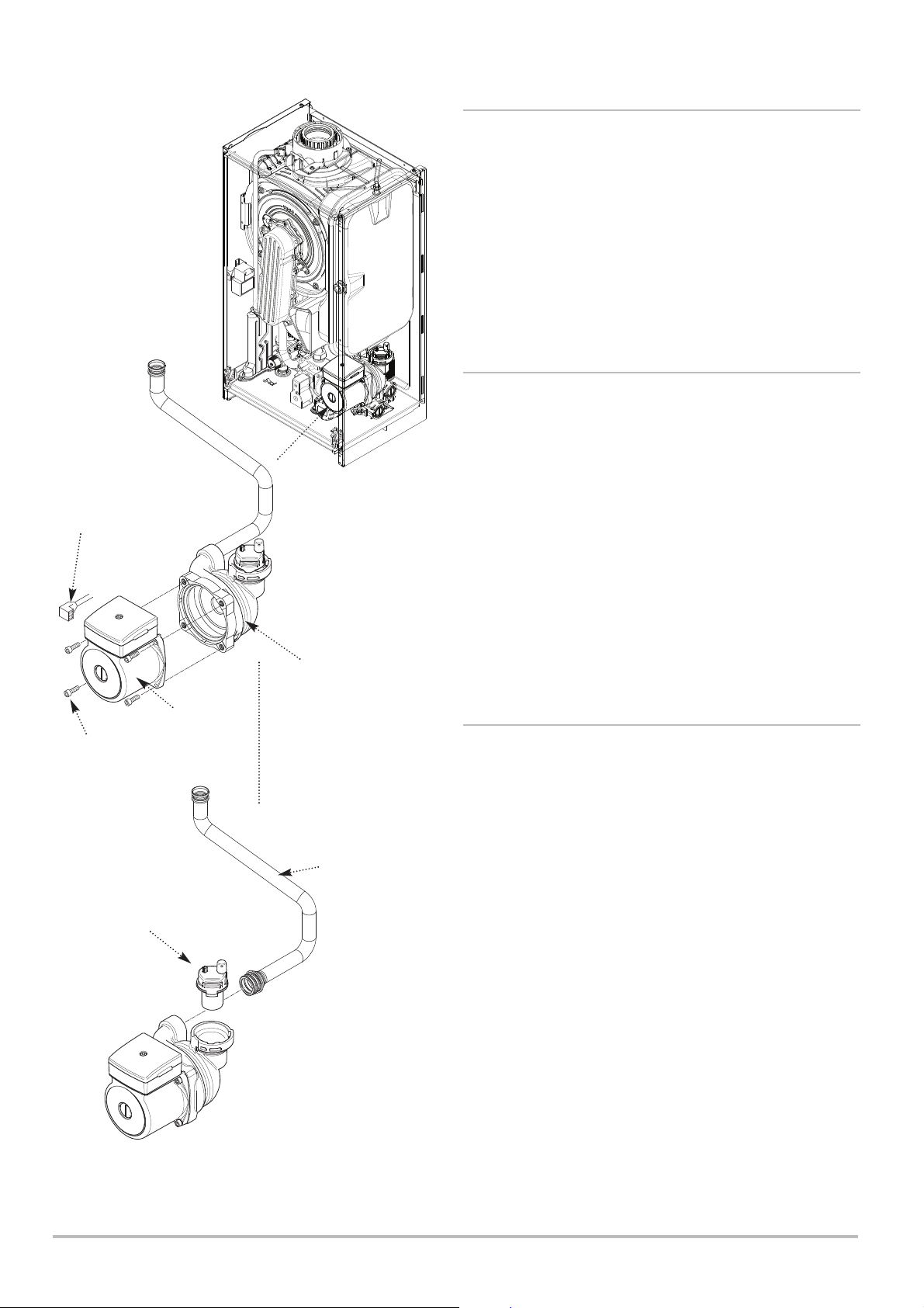
10 Maintenance
Electrical
Supply Plug
Control Box
removed for clarity
10.3.11 Pump - Head Only (Fig. 57)
1. Disconnect the electrical supply plug from the pump.
2. Close the flow and return isolation taps and drain the boiler
primary circuit. For ease of access remove the diverter valve
motor (10.3.20).
3. Remove the socket head screws securing the pump head to
the body and draw the head away.
4. Reassemble in reverse order.
10.3.12 Pump - Complete (Fig. 58)
1. Disconnect the electrical supply plug from the pump.
2. Close the flow and return isolation taps and drain the boiler
primary circuit. For ease of access remove the heating pressure
gauge (10.3.15) & diverter valve motor (10.3.20).
3. Undo the three screws securing the body to the inlet
assembly and pump flow pipe. Draw the complete pump
forwards.
Socket Headed
Screw
Automatic
Air Vent
Pump Head
Fig. 57
Pump Body
Pump Flow
Pipe
4. Remove the automatic air vent and transfer to the new pump
body.
5. Examine the ‘O’ ring seals, replacing if necessary and
reassemble in reverse order.
10.3.13 Automatic Air Vent (Fig. 58)
1. See Section 10.3.23 to remove the expansion vessel. Close
the flow and return isolation taps and drain the primary circuit.
2. The automatic air vent is a bayonet fitting. Remove by twisting
anticlockwise.
3. Fit the new automatic air vent, ensuring the ‘O’ ring is fitted
and the cap is open . Reassemble in reverse order.
Fig. 58
58 EcoBlue Plus Combi 7212136 - 02 (08/14)
Page 59
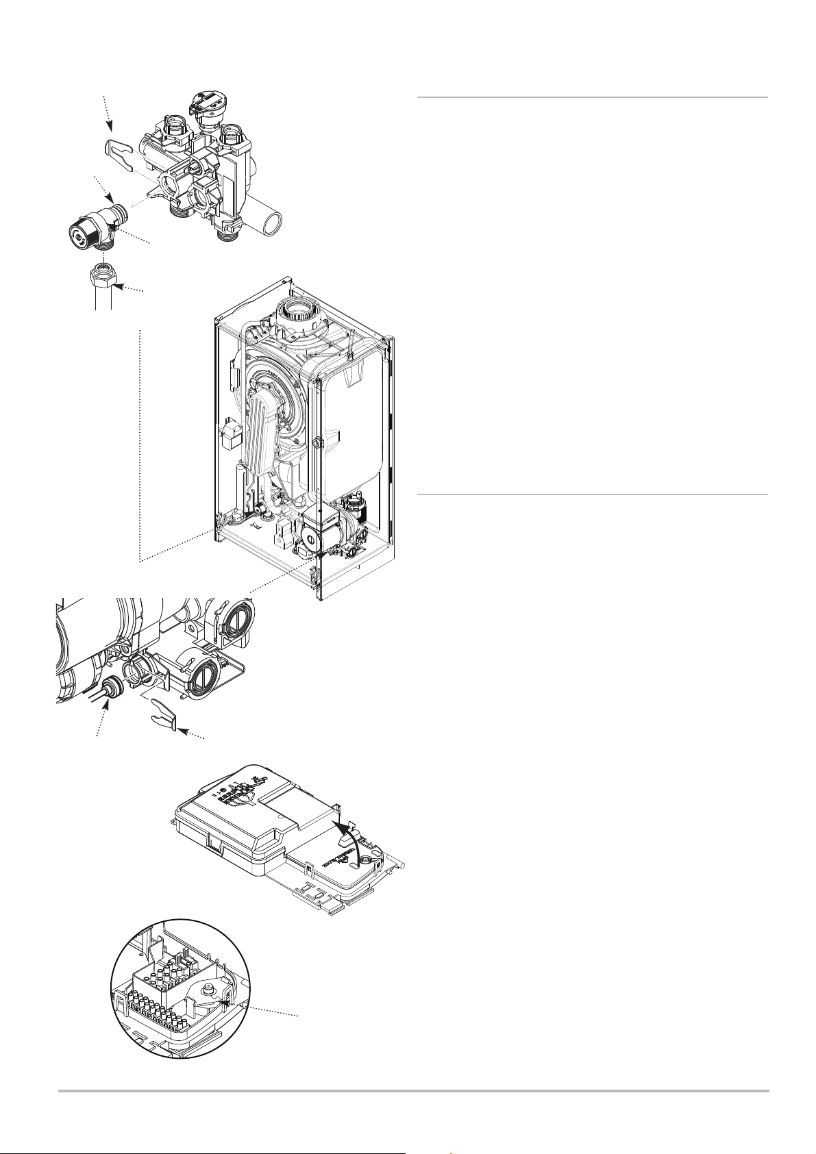
Maintenance 10
Clip
‘O’ Ring Seal
Fig. 59
Pressure
Relief Valve
Discharge
Pipe
10.3.14 Safety Pressure Relief Valve (Fig. 59)
1. Close the flow and return isolation taps and drain the primary
circuit.
2. To aid access disconnect the igniter plug & disconnect the two
pipes from the top of the condensate trap and the drain pipe from
the trap outlet. Undo the screw & washer securing the trap to the
boiler lower panel.
3. Disengage the lip on the trap from the slotted bracket and
remove the trap, taking care not to spill any residual condensate.
4. Disconnect the discharge pipe from the pressure relief valve
and remove the sealing grommet.
5. Pull off the clip retaining the valve and withdraw it from the
outlet assembly.
6. Fit the new valve and ‘O’ ring seal and reconnect the
discharge pipe. Ensure the grommet is in place to maintain the
integrity of the case seal. Refit the condensate trap.
10.3.15 Heating Pressure Gauge (Figs. 60 & 61)
Heating Pressure
Gauge Capillary
Fig. 60
Clip
Control Box
removed for clarity
1. Close the flow and return isolation taps and drain the primary
circuit.
2. Hinge the control box downwards. To aid access remove the
diverter valve motor. Remove the clip securing the pressure
gauge capillary to the hydraulic assembly.
3. Disengage the securing tabs and open the terminal block
cover. Prise apart the clips that hold the gauge cap.
4. Remove the gauge, cap and gasket.
5. Fit the new gauge, ensuring that the capillary is routed to
prevent any sharp bends. Locate the ridge on the gauge body in
the slot in the control box.
6. Reassemble in reverse order and ensure the gasket is in
position to maintain the integrity of the case seal.
Heating
Pressure
Gauge
Fig. 61
7212136 - 02 (08/14) EcoBlue Plus Combi 59
Page 60
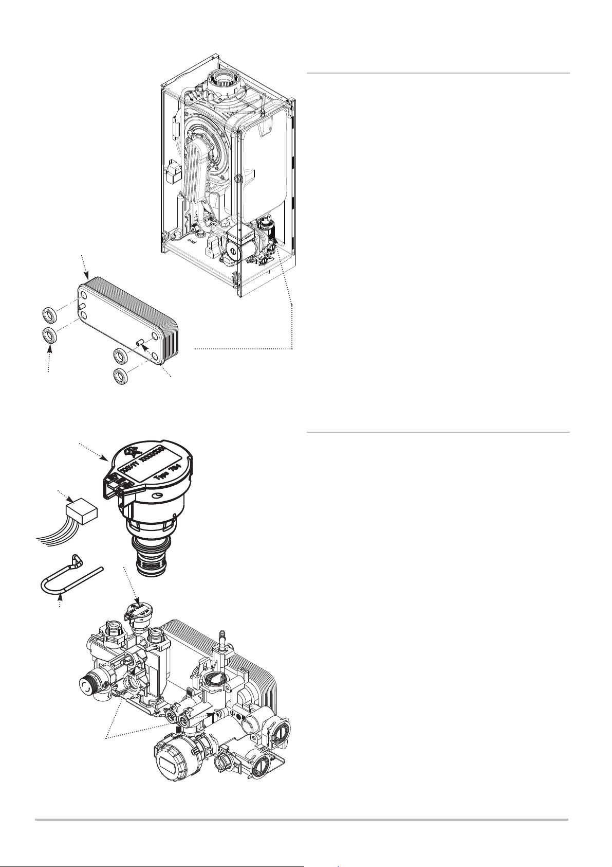
10 Maintenance
Plate Heat
Exchanger
Control Box
removed for clarity
10.3.16 Plate Heat Exchanger (Fig. 62 & 63)
1. Close the flow & return isolation taps and the cold mains inlet.
Drain the primary circuit and draw off any residual DHW.
2. Refer to Section 10.2 paragraphs 5 to 9 and remove the fan
etc. Also remove the diverter valve motor and disconnect the
pump cable.
3. Undo the screws securing the plate heat exchanger to the
hydraulic assembly.
4. Withdraw the plate heat exchanger by manoeuvring it to the
rear of the boiler, then upwards and to the left to remove.
Seals
5. There are four rubber seals between the hydraulic assembly
and heat exchanger which may need replacement.
6. Ease the seals out of the hydraulic assembly. Replace
carefully, ensuring that the seal is inserted parallel and pushed
fully in.
Rubber Seal
Hydraulic
Pressure Sensor
Plug
Securing Clip
(captive)
Fig. 62
R.H. Stud -
Note offset
7. When fitting the new heat exchanger note that the right hand
location stud is offset towards the centre (Fig. 62).
8. Reassemble in reverse order.
10.3.17 Hydraulic Pressure Sensor (Fig. 63)
1. Close the flow and return isolation taps and drain the primary
circuit. For ease of access remove the fan and collector
assembly.
2. Remove the plug from the sensor and pull the retaining clip
forwards. The clip is captive and does not need to be fully
removed.
3. Reassemble in reverse order.
Fig. 63
Plate Heat Exchanger
Securing Screws
Pump, Gas Valve
Assemblies and Pipework
removed for clarity
60 EcoBlue Plus Combi 7212136 - 02 (08/14)
Page 61
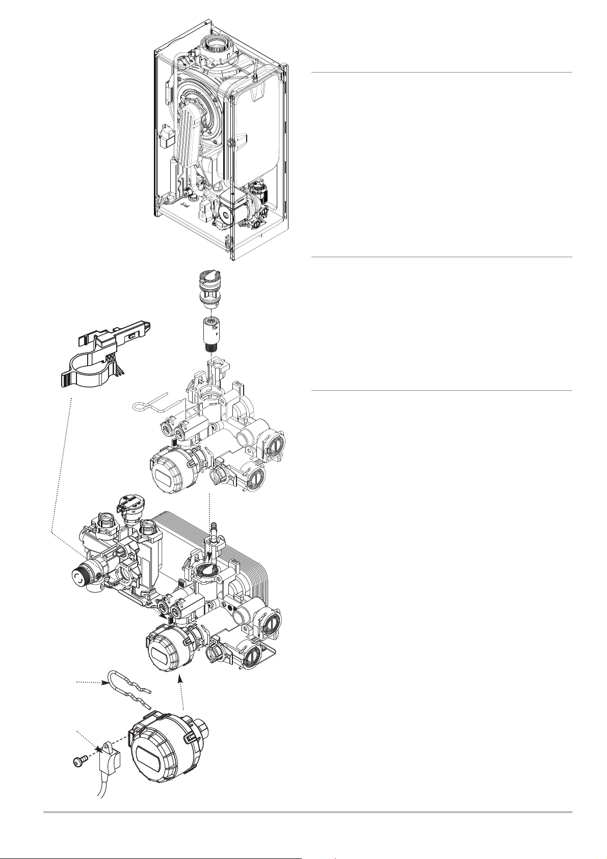
Maintenance 10
10.3.18 DHW Flow Regulator & Filter (Fig. 64)
1. Remove the Fan & Collector (13.2). Close the cold mains inlet
and draw off any residual DHW.
2. Pull out the securing clip and prise the regulator and filter
assembly out of the hydraulic inlet assembly.
3. Twist the body to unlock the bayonet connection and remove
the regulator.
4. Examine and clean the filter, and reassemble in reverse order.
Control Box
removed for clarity
DHW Flow Sensor
(‘Hall Effect’ Sensor)
Fig. 65
DHW Flow
Regulator & Filter
Fig. 64
10.3.19 DHW Flow Sensor (‘Hall Effect’ Sensor)
(Fig. 65)
1. Pull the sensor off the DHW inlet manifold.
2. Disconnect the plug from the sensor and connect it to the new
component.
3. Fit the new sensor, ensuring it is correctly oriented and fully
engaged over the manifold.
10.3.20 Diverter Valve Motor (Fig. 66)
1. Undo the screw securing the electrical plug to the motor unit.
Disconnect the plug.
2. Hold the motor in place against the spring pressure of the
valve and remove the securing clip.
3. Remove the motor.
4. When fitting the new motor it will be necessary to hold the unit
firmly while depressing the valve return spring.
Pump, Gas Valve
Assemblies and Pipework
removed for clarity
Securing
Clip
Electrical Plug
Fig. 66
7212136 - 02 (08/14) EcoBlue Plus Combi 61
Diverter Valve
Motor
Page 62
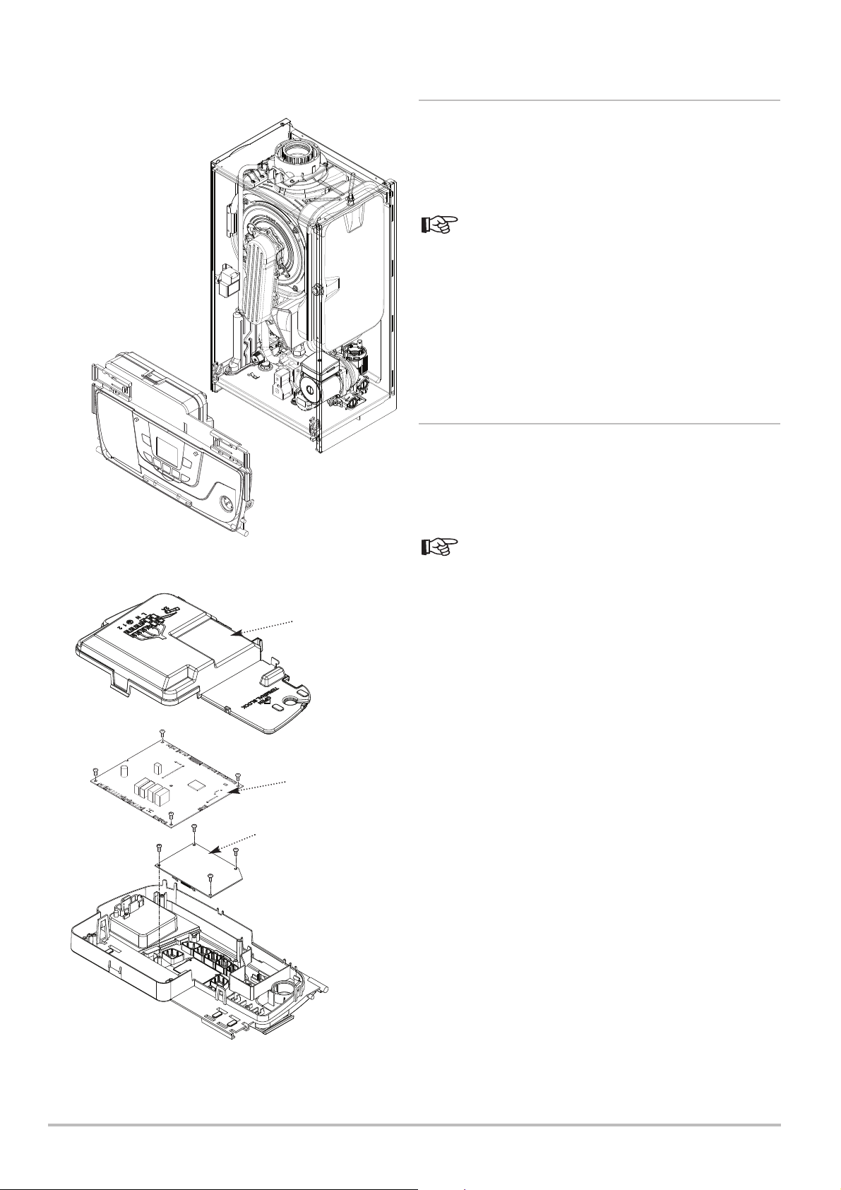
10 Maintenance
10.3.21 Main P.C.B. (Fig. 64)
1. Ensure that the power to the boiler is isolated.
2. Release the clips securing the control box cover and lift away.
3. Note the position of all plugs and wires on the P.C.B. and
disconnect them.
See Section 3.3 Electrical Diagram for details.
4. Undo the 5 securing screws and remove the P.C.B. It is
retained at the left by two spring latches and the right hand edge
locates in a slot.
5. Reassemble in reverse order, ensuring that the harnesses to
the Control P.C.B. and terminal M2 are routed under the Main
P.C.B. Check the operation of the boiler.
10.3.22 Boiler Control P.C.B. (Fig. 64)
1. Ensure that the power to the boiler is isolated.
Fig. 67
Control
Box Cover
Main P.C.B.
Boiler Control P.C.B.
2. Release the clips securing the control box cover and lift away.
3. Note the position of all plugs and wires on the P.C.B. and
disconnect them.
See Section 3.3 Electrical Diagram for details.
4. Undo the 5 securing screws and remove the P.C.B. It is
retained at the left by two spring latches and the right hand edge
locates in a slot.
5. Disconnect the link harness between the Main & Control
P.C.B.’s and undo the 4 screws securing the Control P.C.B.
6. Remove the Control P.C.B. and fit the new component.
Reassemble in reverse order, ensuring that the harnesses to the
Control P.C.B. and terminal M2 are routed under the Main P.C.B.
Check the operation of the boiler.
62 EcoBlue Plus Combi 7212136 - 02 (08/14)
Page 63
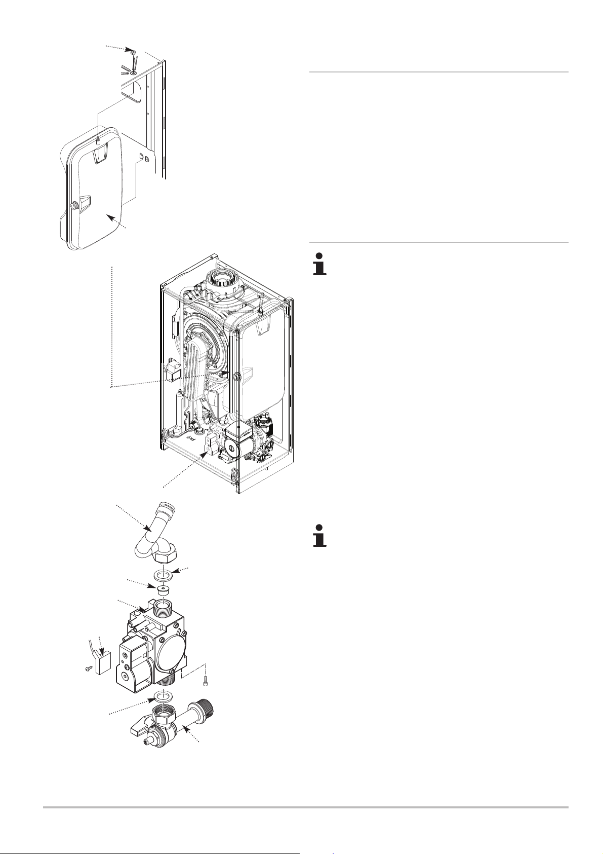
Lock Nut
Maintenance 10
10.3.23 Expansion Vessel
1. Close the flow and return isolation taps and drain the primary
circuit.
2. Prise off the securing clip and disconnect the braided hose
from the vessel.
3 . Whilst supporting the vessel undo the locknut and manoeuvre
the vessel out of the boiler.
4. Reassemble in reverse order.
Fig. 69
Gas Feed
Pipe
Expansion
Vessel
10.3.24 Gas Valve (Fig. 69)
After replacing the valve the CO2 must be checked and
adjusted as detailed in Section 10.3.25 Setting the Gas
Valve. Only change the valve if a suitable calibrated
combustion analyser is available, operated by a
competent person - see section 10.1.3.
1. Undo the screw and disconnect the electrical plug.
2. Turn the gas cock off and undo the nut on the gas valve inlet
underneath the boiler.
3. Undo the nut on the gas valve outlet. Ease the pipe aside.
NOTE: The gas nozzle injector is inserted in the gas valve outlet.
4. Remove the screws securing the gas valve to the boiler
bottom panel. Remove the valve.
5. Transfer the gas nozzle injector to the new valve, ensuring it
sits in the valve outlet. Examine the sealing washers, replacing if
necessary.
6. Reassemble in reverse order.
Check gas tightness & CO2 !
Gas Nozzle Injector
Gas Valve
Electrical
Plug
Washer
Fig. 68
7212136 - 02 (08/14) EcoBlue Plus Combi 63
Washer
Gas Cock
Page 64
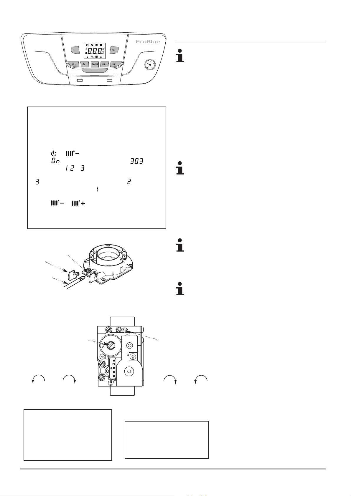
10 Maintenance
/P
R
/R
++
10.3.25 Setting the Gas Valve (CO2Check)
The CO2 must be only be checked and adjusted to set
the valve if a suitable calibrated combustion analyser is
available, operated by a competent person - see
Section 10.1.3.
1. The combustion (CO2) may be checked after running the
boiler for several minutes. To do this it is necessary to operate
the boiler in ‘Chimney Sweep Mode’.
‘Chimney Sweep Mode’
• This function must not be activated whilst the burner is lit.
• The case front panel must be fitted when checking
combustion.
• Ensure the system is cold
1. Press & together and hold for at least 6
R
seconds. is displayed briefly followed by flashing
alternately with , or .
2. represents MAXIMUM HEATING input, represents
MAXIMUM DHW input whilst denotes MINIMUM input.
3. Press or to adjust the input.
4. The valve must be checked and set at MAXIMUM DHW
input & MINIMUM input.
Flue Sampling
Point
Plug
Analyser Probe
Fig. 70
The CO2should be 8.7% ± 0.2 at MAXIMUM
2. It is possible to alter the CO2by adjustment of the gas valve.
At maximum rate the Throttle Adjustment Screw should be
turned, using a suitable 2.5mm hexagon key, until the correct
reading is obtained (Fig. 100).
Turning clockwise will reduce the CO2. Anticlockwise
will increase th e CO2.
3. The CO2must then be checked at minimum rate.
The CO2should be 8.4% ± 0.2 at MINIMUM
4. With the boiler on minimum, the Offset Adjustment Screw
must be altered, using a suitable 4mm hexagon key, after
removing the cap (Fig. 100).
Turning anti-clockwise will reduce the CO2. Clockwise
will increase th e CO2.
5. Check the Combustion Performance (CO/CO2ratio). This
must be less than 0.004.
Refit the sampling point plug and ensure there is no
leakage of products
RQ
ADJ.
R
.
P
EV2
Throttle
Adjustment Screw
(cover removed)
EV1
Reduce CO
at max. rate
Increase CO
2
at max. rate
2
Reduce CO
at min. rate
Adjustment
(cap fitted)
Increase CO
2
at min. rate
Offset
Screw
P. OU T
VENT
D
A
J
.
.
1 2 3 4
2
Fig. 100
If the CO2is reset at minimum
Gas Valve
rate it must be rechecked at
maximum rate again and
adjusted if required. If the CO
2
is reset at maximum rate it must
be rechecked at minimum rate
and adjusted if required.
64 EcoBlue Plus Combi 7212136 - 02 (08/14)
Do not turn the adjustment
screws more than 1/8 of a turn
at a time. Allow the analyser
reading to settle before any
further adjustment
Page 65
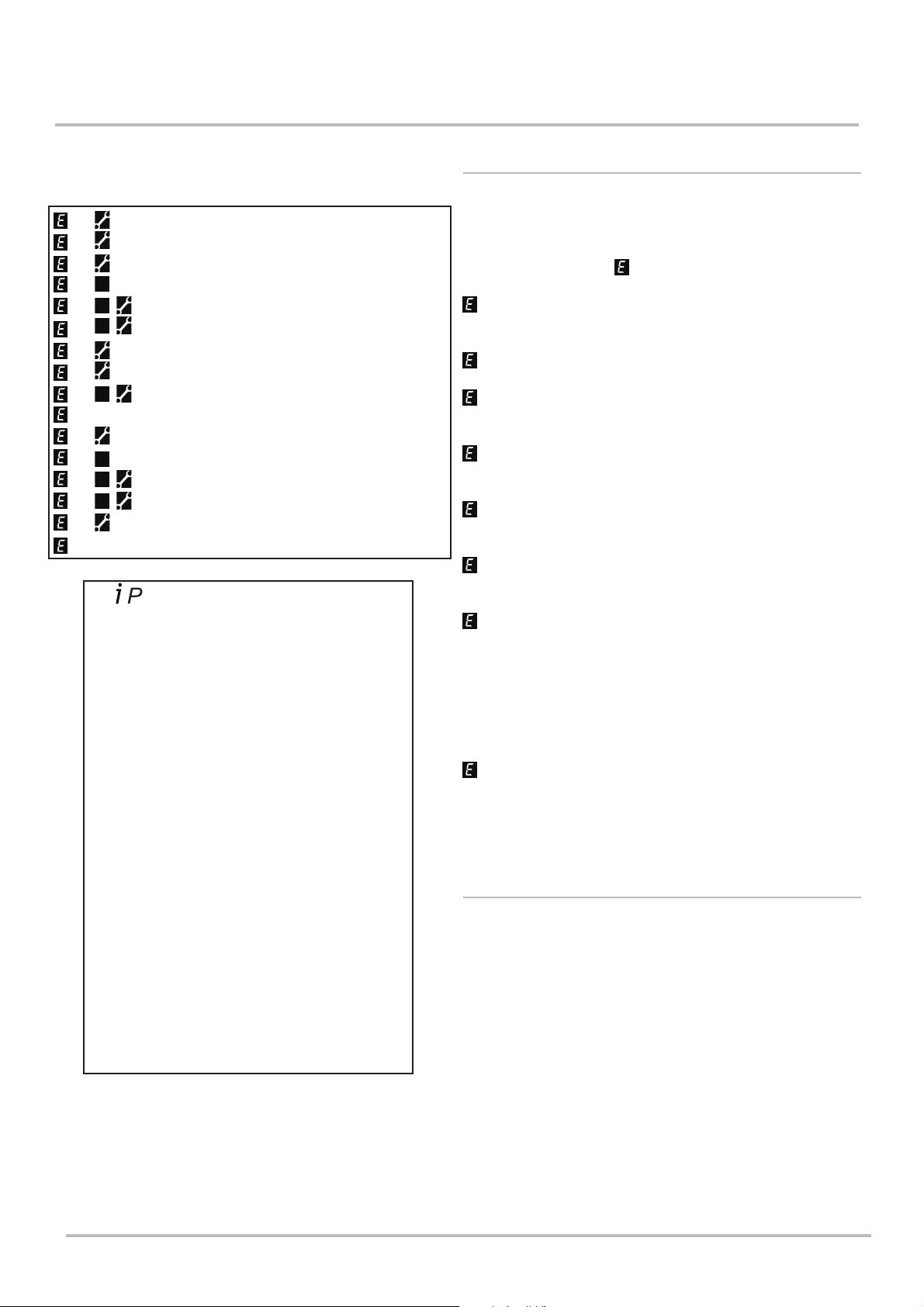
11 Troubleshooting
RRRRR
R
R
Troubleshooting 11
Table Of Error Codes
20
28
40
109
110
111
117
118
125
128
130
133
151
160
321
384
The button can be pressed so that the display
shows
the following information:‘00’ alternates with Sub-Code (only when fault on
boiler) or ‘000’
‘01’ alternates with CH Flow Temperature
‘02’ alternates with Outside Temperature (where
Sensor fitted)
‘03’ alternates with stored DHW Temperature
‘04’ alternates with DHW Temperature
‘05’ alternates with System Water Pressure
‘06’ alternates with CH Return Temperature
‘07’ alternates with Flue Temperature
‘08’ - not used
‘09’ alternates with Collector Temperature
‘10’ alternates with Zone 1 CH Flow Temperature
‘11’ alternates with Zone 2 CH Flow Temperature
‘12’ alternates with Ionization current
‘13’ alternates with Burner working hours
‘14’ alternates with Zone 1 CH mode
‘15’ alternates with Zone 2 CH mode
‘16’ alternates with DHW circuit operating mode
‘17’ alternates with Boiler operating mode
‘18’ alternates with Solar plant operating mode
‘19’ alternates with Manufacturer information
‘20’ alternates with Manufacturer information
Central Heating NTC Fault
Flue NTC Fault
Central Heating Return NTC Fault
Possible Circulation Fault
Safety Thermostat Operated (pump fault)
Safety Thermostat Operated (over temperature)
Primary System Water Pressure Too High
Primary System Water Pressure Too Low
Circulation Fault (Primary)
Flame Failure (no lock-out)
Flue NTC Operated
Interruption Of Gas Supply or Flame Failure
Flame Failure
Fan or Fan Wiring Fault
Hot Water NTC Fault
False Flame
11.1 Error Codes
1. If a fault occurs on the boiler an error code may be shown by
the facia display.
2. The codes are a flashing number, either two or three digit,
preceded by the symbol :-
followed by 20, 28, 40, 160 or 321 indicates possible faulty
components.
110 and 111 indicate overheat of the primary system water.
117 is displayed when the primary water pressure is greater
than 2.7 bar. Restoring the correct pressure will reset the error.
118 is displayed when the primary water pressure is less than
0.5 bar. Restoring the correct pressure will reset the error.
133, indicates that the gas supply has been interrupted,
ignition has failed or the flame has not been detected.
128 is displayed if there has been a flame failure during
normal operation.
125 is displayed in either of two situations:i) If within 15 seconds of the burner lighting the boiler
temperature has not changed by 1°C.
ii) If within 10 minutes of the burner lighting the boiler actual
temperature twice exceeds the selected temperature by 30°.
In these instances poor primary circulation is indicated.
3. By pressing the 'Reset' button for 1 to 3 seconds when
110, 125 & 133 are displayed it is possible to relight the boiler.
4. If this does not have any effect, or the codes are displayed
regularly further investigation is required.
11.2 Fault Finding
1. Check that gas, water and electrical supplies are available at
the boiler.
2. Electrical supply = 230V ~ 50 Hz.
3. The preferred minimum gas pressure is 20 mb (NG).
4. Carry out electrical system checks, i.e. Earth Continuity,
Resistance to Earth, Short Circuit and Polarity with a suitable
meter.
NOTE: These checks must be repeated after any servicing or
fault finding.
5. Ensure all external controls are calling for heat and check all
external and internal fuses. Before any servicing or replacement
of parts, ensure the gas and electrical supplies are isolated.
7212136 - 02 (08/14) EcoBlue Plus Combi 65
Page 66
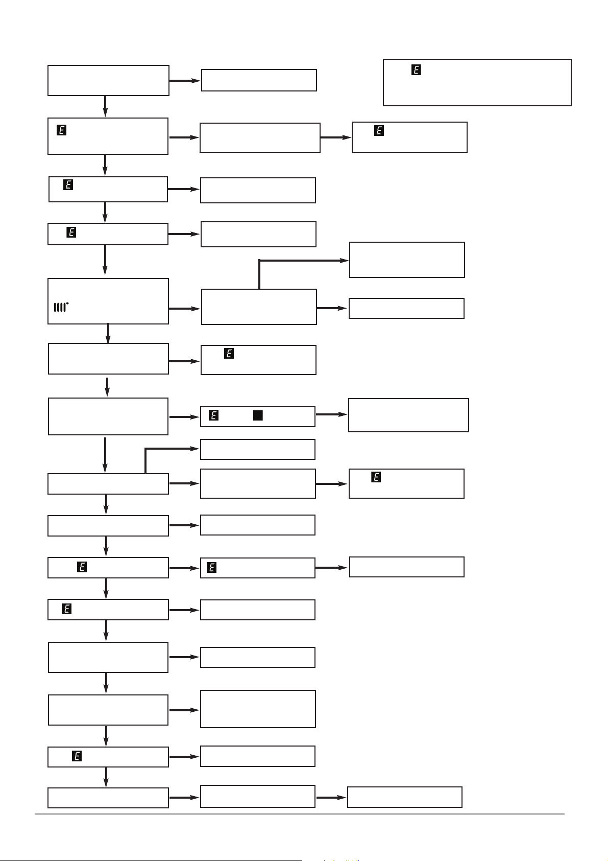
11 Troubleshooting
R
Refer to “Illustrated Wiring Diagram” for position of terminals and components
Central Heating - Follow operational sequence
Turn on mains power
The display illuminates
YES
110, 125, 133, or 384
flashing
NO
20, 28, 40 or 321
flashing
NO
117 or 118 flashing
NO
Set Central Heating
temperature to Maximum.
symbol flashing, pump
runs
YES
Fan runs at correct speed
NO
YES
YES
YES
NO
NO
Go to section ‘A’
Press the reset button for 1
to 3 seconds
Go to section ‘D’
Go to section ‘I’
NO
Ensure all controls and
programmers are calling
for heat
160 flashing
Go to section ‘C’
YES
If 110 or 384 is flashing or re-occurs
regularly, check all PCB connections. If this
has no effect replace the PCB.
If 110 is still flashing
go to section ‘H’
Ensure controls are set to
demand and verify the
contacts are closed
Go to section ‘B’
YES
Spark at ignition electrodes
up to 5 seconds & for 4
attempts
YES
NO
Burner lights
YES
Flame Displayed
YES
109 flashing
NO
110 or 111 flashing
NO
Diverter Valve open to
Central Heating circuit
YES
Burner modulates to
maintain set temperature
YES
130 flashing
NO
YES
NO
YES
YES
NO
NO
YES
133 and flashing
Go to section ‘E’
Burner goes out after 5
seconds
Check polarity
125 flashing after 1 min
Go to section ‘H’
Go to section ‘K’
Check Heating Flow
sensor.
Go to section ‘D’
Go to section ‘M’
YES
YES
Go to section ‘F’. Press the
reset button for 1 to 3
seconds
133 flashing
Go to section ‘G’
Go to section ‘J’
NO
Burner goes out
66 EcoBlue Plus Combi 7212136 - 02 (08/14)
YES
Fan stops after 15
seconds
YES
Boiler operation correct
Page 67
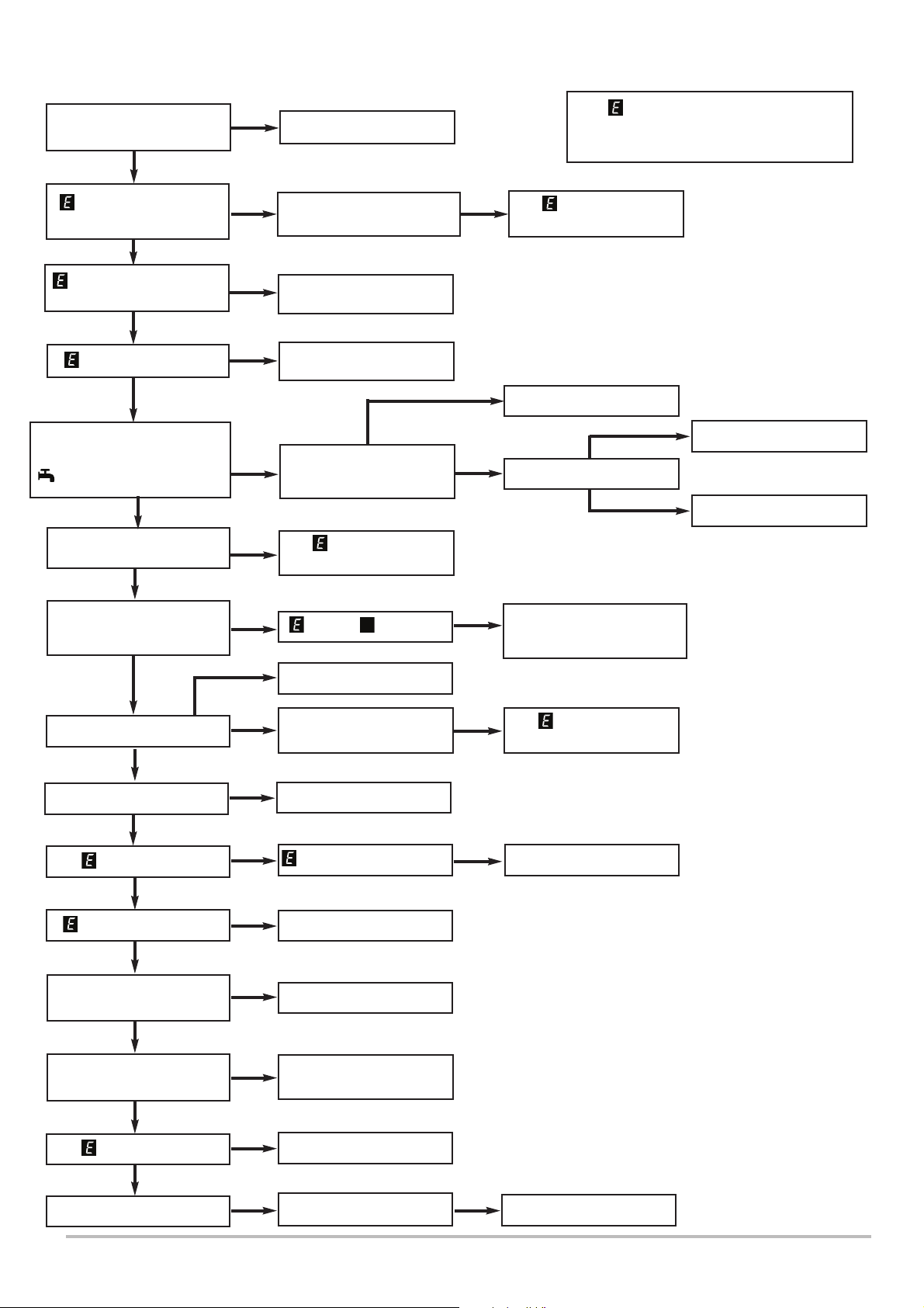
Domestic Hot Water - Follow operational sequence
R
Turn on mains power
The display illuminates
YES
NO
Go to section ‘A’
Troubleshooting
If 110 or 384 is flashing or re-occurs
regularly, check all PCB connections. If this
has no effect replace the PCB.
11
110, 125, 133, or 384
flashing
NO
20, 28, 40, 50 or 321
flashing
NO
117 or 118 flashing
NO
Set Hot Water temperature to
Maximum & fully open hot tap.
symbol flashing, pump runs
YES
Fan runs at correct speed
NO
Spark at ignition electrodes
up to 5 seconds & for 4
attempts
YES
YES
YES
NO
NO
NO
Press the reset button for 1
to 3 seconds
Go to section ‘D’
Go to section ‘I’
NO
DHW flow rate greater
than 2litres/min
160 flashing
Go to section ‘C’
133 and flashing
YES
YES
If 110 is still flashing
go to section ‘H’
Go to section ‘L’
NO
Burner lights
YES
Go to section ‘F’. Press the
reset button for 1 to 3
seconds
Go to section ‘L’
Go to section ‘B’
YES
NO
Burner lights
YES
Flame Displayed
109 flashing
NO
110 or 111 flashing
NO
3 Way Valve open to
Domestic Hot Water circuit
YES
Burner modulates to
maintain set temperature
NO
130 flashing
YES
NO
YES
YES
NO
NO
YES
Go to section ‘E’
Burner goes out after 5
seconds
Check polarity
125 flashing after 1 min
Go to section ‘H’
Go to section ‘K’
Check CH NTC sensor.
Go to section ‘D’
Go to section ‘M’
YES
133 flashing
Go to section ‘G’
Go to section ‘J’
NO
Burner goes out
7212136 - 02 (08/14) EcoBlue Plus Combi 67
YES
Fan stops after 15
seconds
YES
Boiler operation correct
Page 68
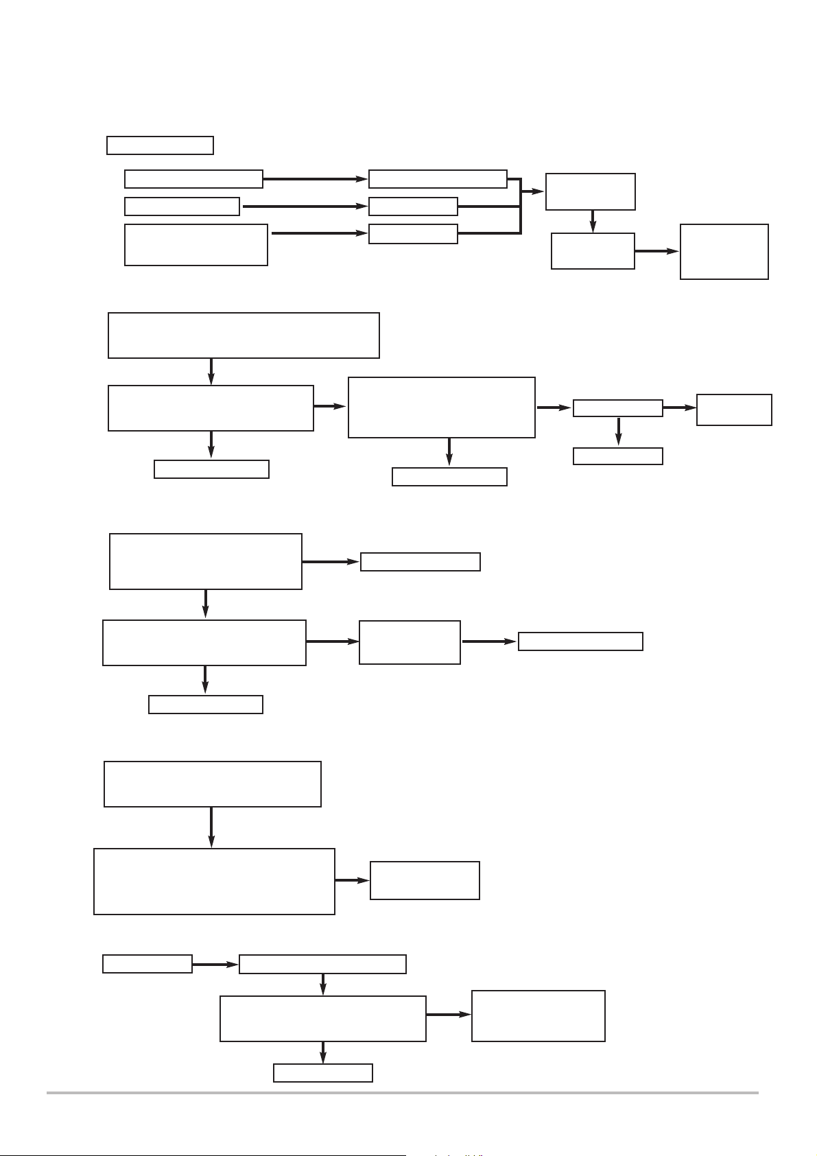
11
Troubleshooting
Fault Finding Solutions Sections
A
B
Is there 230V at:
1.
Main terminals L and N Check electrical supply
2.
Main terminal fuse Replace fuse
3.
PCB - X10 connector
Main terminals L and N
Switch to DHW mode maximum flow and press
reset. During next 3 minutes check:-
230V at PCB - X13 connector
(between blue & brown - see Wiring
Diagram)
NO
Replace PCB
NO
NO
NO
Check wiring
230V between PCB - X13
YES
connector (blue) and PCB - X11
connector (black) - see Wiring
Diagram
NO
Replace PCB
Connection
YES
OK at X40
Display
illuminated
230V at pump
NO
Check wiring
NO
YES
Display or
Main PCB
fault
Replace
pump
C
D
Fan connections correct at fan &
PCB X11 and X23 connectors -
see Wiring Diagram.
YES
230V at PCB - X11 connector
(between blue & brown - see Wiring
Diagram)
NO
Replace PCB
Temperature sensor faulty.
Check correct location and wiring.
YES
Cold resistance approximately
10k @ 25° C (CH & DHW sensor)
20k @ 25° C (Flue sensor)
(resistance reduces with increase in temp.)
YES
NO
Make connections
Fan jammed or
faulty wiring
NO
Replace sensor
& reset boiler
YES
Replace fan or wire
E
68 EcoBlue Plus Combi 7212136 - 02 (08/14)
Gas at burner
NO
Ensure gas is on and purged
Check wiring and PCB - X14
connector see Wiring Diagram
NO
Replace PCB
YES
Replace gas valve &
Check combustion
Page 69
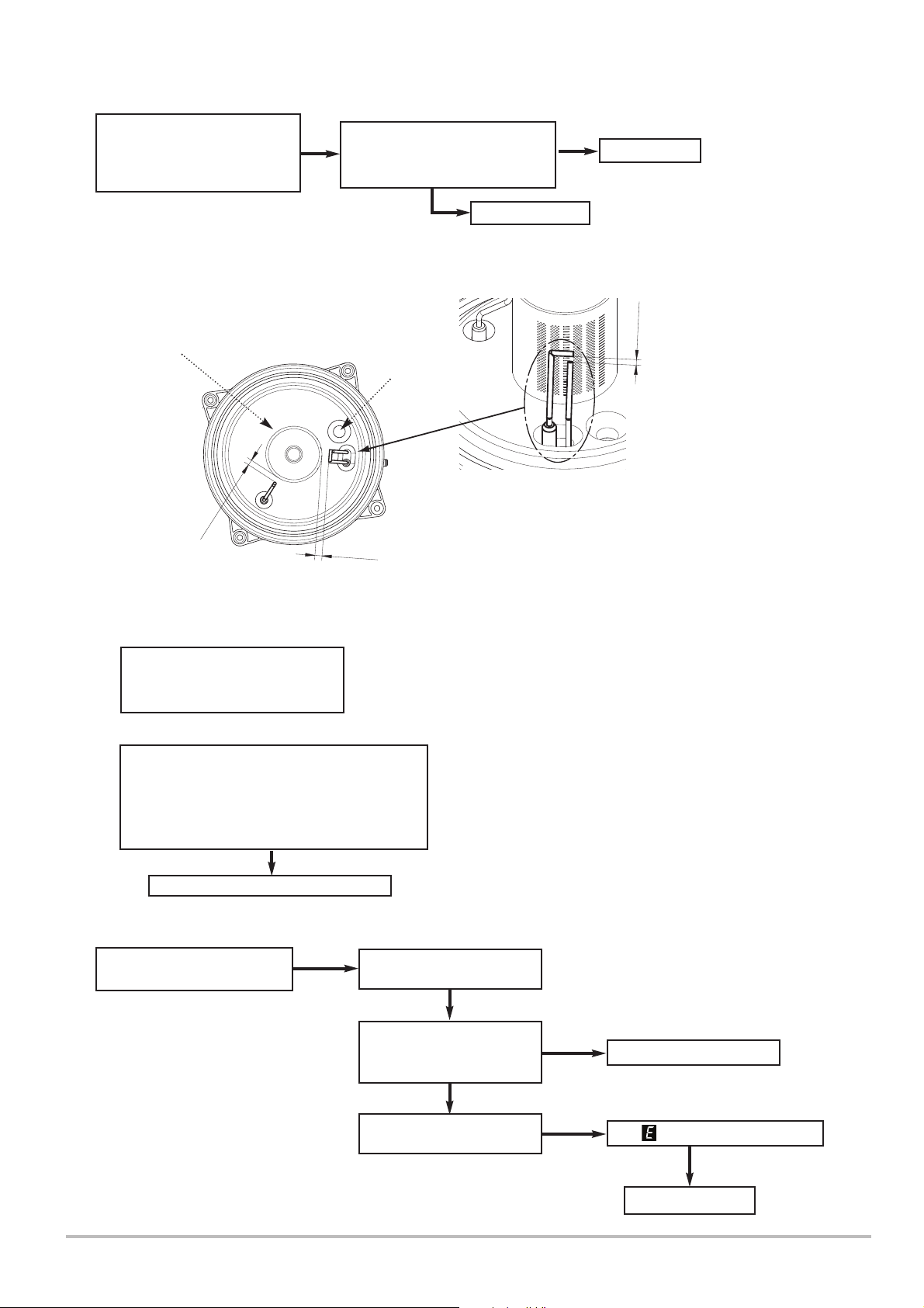
Troubleshooting 11
F
Check and correct if necessary
1. Ignition electrode and lead
2. Electrode connection
3. Spark gap and position
Burner
Flame
Sensing
Electrode
7.5
1
±
YES
Check wiring (see Diagram)
and 230V at PCB X14 (between
blue & brown from igniter)
Viewing Window
1
0
±
1
YES
Replace Igniter
NO
Spark Ignition
Electrode
Replace PCB
0.5
±
4
G
H
Electrode Position
1.
2.
Check supply pressure at the
gas cock test point (Fig. 41):-
Natural Gas - Minimum 17 mbar
Check and correct if necessary
1. The set of the gas valve
values - see Section 10.3.25)
(CO
2
2. Flame sensing electrode and lead connections
3. Flame sensing electrode position
Replace sensing electrode or PCB
Safety Thermostat operated
or faulty
NO
Check for and correct any
system faults
NO
Allow to cool. Continuity
across thermostat terminals
more than 1.5 ohm
NO
Check Flow & Return
Sensors - see section ‘D’
7212136 - 02 (08/14) EcoBlue Plus Combi 69
YES
YES
Replace safety thermostat
Is 110 or 111 still flashing ?
YES
Replace PCB
Page 70
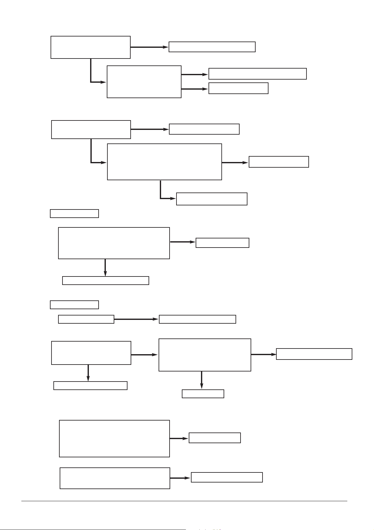
11 Troubleshooting
I
J
K
CH system pressure less than
0.5 bar or greater than 2.7 bar
on digital display
NO
Ensure that the boiler and
system are fully vented
YES
Is there 230V at:
Check wiring and PCB -
X22 connector for approx.
5V DC between green &
black - see Wiring Diagram
Check flow temperature sensor connections
(resistance reduces with increase in temp.)
YES
NO
and position.
Cold resistance approximately
10k @ 25° C (CH sensors)
YES
Restore correct system pressure
YES
NO
System fault - correct
Go to section ‘B’
Replace hydraulic pressure sensor
Replace PCB
NO
Replace sensor
L
1.
PCB - X13 connector terminals between:-
Blue & Black (central heating mode)
Blue & Brown (domestic hot water mode)
see Wiring Diagram
YES
Check diverter valve motor cable
Is there 230V at:
2.
Diverter valve motor Replace diverter valve motor
Is mains water filter &
assembly clean, and rotor
moving freely ?
NO
Clean or replace
YES
YES
NO
Replace PCB
Check wiring and PCB - X22
connector for approx. 5V DC
between red & blue from Hall effect
sensor - see Wiring Diagram
NO
Replace PCB
YES
Replace Hall Effect Sensor
1.
M
70 EcoBlue Plus Combi 7212136 - 02 (08/14)
Temperature sensors faulty.
Cold resistance approximately
10k @ 25° C (CH sensor)
20k @ 25° C (Flue sensor)
(resistance reduces with increase in temp.)
2.
If pump is running the heat exchanger
could be obstructed
NO
YES
Replace sensor
Replace heat exchanger
Page 71

12 Decommissioning
Decommissioning
12
12.1 Decommissioning Procedure
1. Disconnect the gas & electric supplies and isolate them.
2. Drain the primary circuit and disconnect the filling device.
3 . Dismantle the chimney system and remove the boiler from the
wall mounting frame.
7212136 - 02 (08/14) EcoBlue Plus Combi 71
Page 72
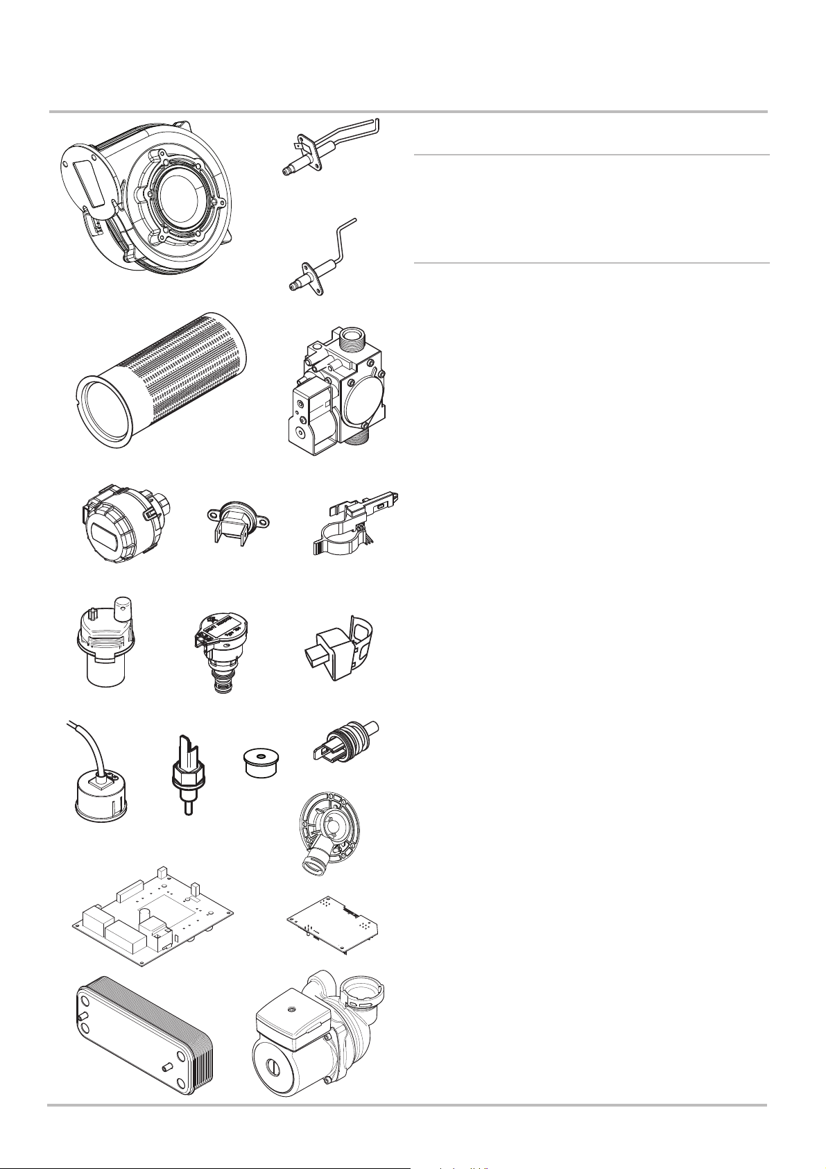
13 Spare Parts
13 Spare Parts
13.1 General
C
1. If, following the annual inspection or maintenance any part of
the boiler is found to need replacing, use Genuine Baxi Spare
Parts only.
13.2 Spare Parts List
A
B
J
F
D
Key Description Manufacturers
No.
No. Part No.
A Fan 720768101
B Burner - 24 & 28 7212447
Burner - 33 7212449
C Spark Ignition Electrode 720767301
E
D Flame Sensing Electrode 7211855
E Gas Valve 7214341
F Safety Thermostat 720765301
G
G Hall Effect Sensor 720061801
I Plate Heat Exchanger 720852401
J Diverter Valve Motor 720776801
K Pump 720777401
M
O
P
M Heating Flow/Return Sensor 720747101
N DHW NTC Sensor 720777001
O Pump Automatic Air Vent 720777601
U
N
P Hydraulic Pressure Switch 720778001
Q Heating Pressure Gauge 7212896
Q
R
V
R Flue Sensor 720851401
S PCB - 24 7211761
PCB - 28 7211762
PCB - 33 7211763
S
W
U Ø5.0 Gas Nozzle Injector - 24 7211862
Ø5.6 Gas Nozzle Injector - 28 7211864
Ø6.6 Gas Nozzle Injector - 33 7214346
V Air/Gas Venturi - 24 7211858
V Air/Gas Venturi - 28 7211859
V Air/Gas Venturi - 33 7211860
I
W Boiler Control HMI PCB 7211868
K
72 EcoBlue Plus Combi 7212136 - 02 (08/14)
Page 73

14 Notes
Notes 14
7212136 - 02 (08/14) EcoBlue Plus Combi 73
Page 74
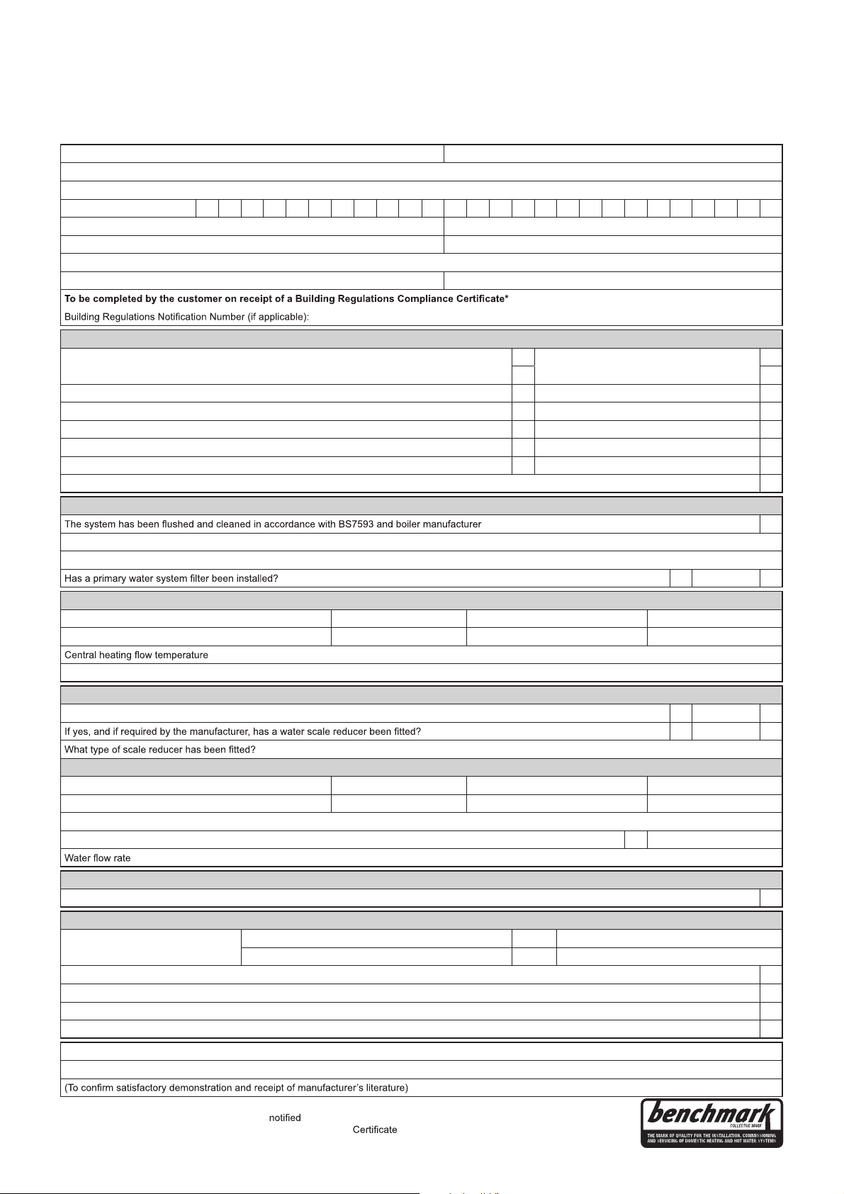
*All installations in England and Wales must be to Local Authority Building Control (LABC) either directly or through a
Competent Persons Scheme. A Building Regulations Compliance
will then be issued to the customer.
www.centralheating.co.uk
© Heating and Hotwater Industry Council (HHIC)
This Commissioning Checklist is to be completed in full by the competent person who commissioned the boiler as a means of demonstrating
compliance with the appropriate Building Regulations and then handed to the customer
to keep for future reference.
Failure to install and commission according to the manufacturer’s instructions and complete this Benchmark Commissioning Checklist will invalidate the
warranty. This does not affect the customer’s statutory rights.
GAS BOILER SYSTEM COMMISSIONING CHECKLIST
Customer name: Telephone number:
Address:
Boiler make and model:
Boiler serial number:
Commissioned by (PRINT NAME): Gas Safe register number:
Company name: Telephone number:
Company address:
Commissioning date:
CONTROLS (tick the appropriate boxes)
Time and temperature control to heating
Room thermostat and programmer/timer Programmable room thermostat
Load/weather compensation Optimum start control
Time and temperature control to hot water Cylinder thermostat and programmer/timer Combination Boiler
Heating zone valves Fitted Not required
Hot water zone valves Fitted Not required
Thermostatic radiator valves Fitted Not required
Automatic bypass to system Fitted Not required
Boiler interlock Provided
ALL SYSTEMS
’s instructions Yes
What system cleaner was used?
What inhibitor was used? Quantity litres
Yes N o
CENTRAL HEATING MODE measure and record:
Gas rate m³/hr OR ft³/hr
Burner operating pressure (if applicable) mbar OR Gas inlet pressure mbar
°C
Central heating return temperature °C
COMBINATION BOILERS ONLY
Is the installation in a hard water area (above 200ppm)? Yes N o
Yes N o
DOMESTIC HOT WATER MODE Measure and Record:
Gas rate m³/hr OR ft³/hr
Burner operating pressure (at maximum rate) mbar OR Gas inlet pressure at maximum rate mbar
Cold water inlet temperature °C
Hot water has been checked at all outlets Yes Temperature °C
I/min
CONDENSING BOILERS ONLY
The condensate drain has been installed in accordance with the manufacturer’s instructions and/or BS5546/BS6798 Yes
ALL INSTALLATIONS
Record the following:
At max. rate: CO ppm AND CO/CO
²
Ratio
At min. rate: (where possible) CO ppm AND CO/CO
²
Ratio
The heating and hot water system complies with
the appropriate Building Regulations Yes
The boiler and associated products have been installed and commissioned in accordance with the manufacturer’s instructions Yes
The operation of the boiler and system controls have been demonstrated to and understood by the customer Yes
The manufacturer’s literature, including Benchmark Checklist and
Service Record, has been explained and left with the customer Yes
Commissioning Engineer’s Signature
Customer’s Signature
www.centralheating.co.uk
74
Page 75
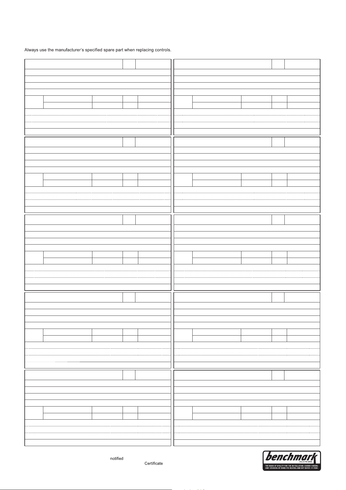
www.centralheating.co.uk
It is recommended that your heating system is serviced regularly and that the appropriate Service Interval Record is completed.
Service Provider
Before completing the appropriate Service Record below, please ensure you have carried out the service as described in the manufacturer’s instructions.
SERVICE RECORD
SERVICE 01
Date:
Engineer name:
Company name:
Telephone No:
Gas safe register No:
Record:
At max. rate: CO ppm AND CO² %
At min. rate:
(Where Possible) CO ppm AND CO
²
%
Comments:
Signature
SERVICE 02
Date:
Engineer name:
Company name:
Telephone No:
Gas safe register No:
Record:
At max. rate: CO ppm AND CO² %
At min. rate:
(Where Possible) CO ppm AND CO
²
%
Comments:
Signature
SERVICE 03
Date:
Engineer name:
Company name:
Telephone No:
Gas safe register No:
Record:
At max. rate: CO ppm AND CO² %
At min. rate:
(Where Possible) CO ppm AND CO
²
%
Comments:
Signature
SERVICE 04
Date:
Engineer name:
Company name:
Telephone No:
Gas safe register No:
Record:
At max. rate: CO ppm AND CO² %
At min. rate:
(Where Possible) CO ppm AND CO
²
%
Comments:
Signature
SERVICE 05
Date:
Engineer name:
Company name:
Telephone No:
Gas safe register No:
Record:
At max. rate: CO ppm AND CO² %
At min. rate:
(Where Possible) CO ppm AND CO
²
%
Comments:
Signature
SERVICE 06
Date:
Engineer name:
Company name:
Telephone No:
Gas safe register No:
Record:
At max. rate: CO ppm AND CO² %
At min. rate:
(Where Possible) CO ppm AND CO
²
%
Comments:
Signature
SERVICE 07
Date:
Engineer name:
Company name:
Telephone No:
Gas safe register No:
Record:
At max. rate: CO ppm AND CO² %
At min. rate:
(Where Possible) CO ppm AND CO
²
%
Comments:
Signature
SERVICE 08
Date:
Engineer name:
Company name:
Telephone No:
Gas safe register No:
Record:
At max. rate: CO ppm AND CO² %
At min. rate:
(Where Possible) CO ppm AND CO
²
%
Comments:
Signature
SERVICE 09
Date:
Engineer name:
Company name:
Telephone No:
Gas safe register No:
Record:
At max. rate: CO ppm AND CO² %
At min. rate:
(Where Possible) CO ppm AND CO
²
%
Comments:
Signature
SERVICE 10
Date:
Engineer name:
Company name:
Telephone No:
Gas safe register No:
Record:
At max. rate: CO ppm AND CO² %
At min. rate:
(Where Possible) CO ppm AND CO
²
%
Comments:
Signature
*All installations in England and Wales must be
to Local Authority Building Control (LABC) either directly or through a
Competent Persons Scheme. A Building Regulations Compliance
will then be issued to the customer.
© Heating and Hotwater Industry Council (HHIC)
75
Page 76

All descriptions and illustrations provided in this leaflet have been
carefully prepared but we reserve the right to make changes and
improvements in our products which may affect the accuracy of the
information contained in this leaflet. All goods are sold subject to our
standard Conditions of Sale which are available on request.
BAXI
A Trading Division of Baxi Heating UK Ltd (3879156)
Brooks House, Coventry Road, Warwick. CV34 4LL
After Sales Service 0844 871 1525 Technical Enquiries 0844 871 1555
Website www.baxi.co.uk
e&oe
© Baxi Heating UK Ltd 2014
7212136 - 02 (08/14)
 Loading...