

Page 1
Please keep these instructions in a safe place.
If you move house please hand them over to the next occupier.
United Kingdom
en
User Guide
High Efficiency Wall Hung Condensing Gas Boiler
Baxi Combi
224 – 228 – 424 — 428
Page 2

Dear Customer,
Thank you very much for buying this appliance.
Please read through the manual carefully before using the product, and keep it in a safe place for later reference. In order to
ensure continued safe and efficient operation we recommend that the product is serviced regularly. Our service and customer
service organisation can assist with this.
We hope you enjoy years of problem-free operation with the product.
Page 3

Contents
7661618 - 1 - 04072016 3
Contents
1 Safety . . . . . . . . . . . . . . . . . . . . . . . . . . . . . . . . . . . . . . . . . . . . . . . . . . . . . . . . . . . . . . . . . . . . . . . . . . . . . . . . . . . . . . . . . . . . 5
1.1 General safety instructions . . . . . . . . . . . . . . . . . . . . . . . . . . . . . . . . . . . . . . . . . . . . . . . . . . . . . . . . . . . . . . . . . . . . . . . 5
1.2 Recommendations . . . . . . . . . . . . . . . . . . . . . . . . . . . . . . . . . . . . . . . . . . . . . . . . . . . . . . . . . . . . . . . . . . . . . . . . . . . . . 6
1.2.1 The Benchmark Scheme . . . . . . . . . . . . . . . . . . . . . . . . . . . . . . . . . . . . . . . . . . . . . . . . . . . . . . . . . . . . . . . . . 6
1.2.2 Benchmark Commissioning Checklist . . . . . . . . . . . . . . . . . . . . . . . . . . . . . . . . . . . . . . . . . . . . . . . . . . . . . . . 6
1.3 Liabilities . . . . . . . . . . . . . . . . . . . . . . . . . . . . . . . . . . . . . . . . . . . . . . . . . . . . . . . . . . . . . . . . . . . . . . . . . . . . . . . . . . . . . 6
1.3.1 User's liability . . . . . . . . . . . . . . . . . . . . . . . . . . . . . . . . . . . . . . . . . . . . . . . . . . . . . . . . . . . . . . . . . . . . . . . . . .6
1.3.2 Installer's liability . . . . . . . . . . . . . . . . . . . . . . . . . . . . . . . . . . . . . . . . . . . . . . . . . . . . . . . . . . . . . . . . . . . . . . . 7
1.3.3 Manufacturer's liability . . . . . . . . . . . . . . . . . . . . . . . . . . . . . . . . . . . . . . . . . . . . . . . . . . . . . . . . . . . . . . . . . . . 7
2 About this manual . . . . . . . . . . . . . . . . . . . . . . . . . . . . . . . . . . . . . . . . . . . . . . . . . . . . . . . . . . . . . . . . . . . . . . . . . . . . . . . . . . . 8
2.1 General . . . . . . . . . . . . . . . . . . . . . . . . . . . . . . . . . . . . . . . . . . . . . . . . . . . . . . . . . . . . . . . . . . . . . . . . . . . . . . . . . . . . . . 8
2.2 Additional documentation . . . . . . . . . . . . . . . . . . . . . . . . . . . . . . . . . . . . . . . . . . . . . . . . . . . . . . . . . . . . . . . . . . . . . . . . 8
2.3 Symbols used . . . . . . . . . . . . . . . . . . . . . . . . . . . . . . . . . . . . . . . . . . . . . . . . . . . . . . . . . . . . . . . . . . . . . . . . . . . . . . . . . 8
2.3.1 Symbols used in the manual . . . . . . . . . . . . . . . . . . . . . . . . . . . . . . . . . . . . . . . . . . . . . . . . . . . . . . . . . . . . . . 8
2.4 Abbreviations/glossary . . . . . . . . . . . . . . . . . . . . . . . . . . . . . . . . . . . . . . . . . . . . . . . . . . . . . . . . . . . . . . . . . . . . . . . . . . 8
3 Technical specifications . . . . . . . . . . . . . . . . . . . . . . . . . . . . . . . . . . . . . . . . . . . . . . . . . . . . . . . . . . . . . . . . . . . . . . . . . . . . . 10
3.1 Homologations . . . . . . . . . . . . . . . . . . . . . . . . . . . . . . . . . . . . . . . . . . . . . . . . . . . . . . . . . . . . . . . . . . . . . . . . . . . . . . . 10
3.1.1 Certifications . . . . . . . . . . . . . . . . . . . . . . . . . . . . . . . . . . . . . . . . . . . . . . . . . . . . . . . . . . . . . . . . . . . . . . . . . 10
3.2 Technical data . . . . . . . . . . . . . . . . . . . . . . . . . . . . . . . . . . . . . . . . . . . . . . . . . . . . . . . . . . . . . . . . . . . . . . . . . . . . . . . .10
3.2.1 Technical information . . . . . . . . . . . . . . . . . . . . . . . . . . . . . . . . . . . . . . . . . . . . . . . . . . . . . . . . . . . . . . . . . . .10
3.2.2 Dimensions and connections/clearances . . . . . . . . . . . . . . . . . . . . . . . . . . . . . . . . . . . . . . . . . . . . . . . . . . . 11
4 Description of the product . . . . . . . . . . . . . . . . . . . . . . . . . . . . . . . . . . . . . . . . . . . . . . . . . . . . . . . . . . . . . . . . . . . . . . . . . . . . 12
4.1 General description . . . . . . . . . . . . . . . . . . . . . . . . . . . . . . . . . . . . . . . . . . . . . . . . . . . . . . . . . . . . . . . . . . . . . . . . . . . .12
4.2 Operating principle . . . . . . . . . . . . . . . . . . . . . . . . . . . . . . . . . . . . . . . . . . . . . . . . . . . . . . . . . . . . . . . . . . . . . . . . . . . . 12
4.2.1 In operation . . . . . . . . . . . . . . . . . . . . . . . . . . . . . . . . . . . . . . . . . . . . . . . . . . . . . . . . . . . . . . . . . . . . . . . . . . 12
4.3 Control panel description . . . . . . . . . . . . . . . . . . . . . . . . . . . . . . . . . . . . . . . . . . . . . . . . . . . . . . . . . . . . . . . . . . . . . . . 12
4.3.1 Description of the keys . . . . . . . . . . . . . . . . . . . . . . . . . . . . . . . . . . . . . . . . . . . . . . . . . . . . . . . . . . . . . . . . . 12
4.3.2 Description of the display . . . . . . . . . . . . . . . . . . . . . . . . . . . . . . . . . . . . . . . . . . . . . . . . . . . . . . . . . . . . . . . .12
4.4 Accessories and options . . . . . . . . . . . . . . . . . . . . . . . . . . . . . . . . . . . . . . . . . . . . . . . . . . . . . . . . . . . . . . . . . . . . . . . . 13
4.4.1 Optional accessories . . . . . . . . . . . . . . . . . . . . . . . . . . . . . . . . . . . . . . . . . . . . . . . . . . . . . . . . . . . . . . . . . . . 13
5 Operation . . . . . . . . . . . . . . . . . . . . . . . . . . . . . . . . . . . . . . . . . . . . . . . . . . . . . . . . . . . . . . . . . . . . . . . . . . . . . . . . . . . . . . . . .14
5.1 Start-up . . . . . . . . . . . . . . . . . . . . . . . . . . . . . . . . . . . . . . . . . . . . . . . . . . . . . . . . . . . . . . . . . . . . . . . . . . . . . . . . . . . . . 14
5.1.1 Operation checking procedure and basic fault identification . . . . . . . . . . . . . . . . . . . . . . . . . . . . . . . . . . . . . 14
5.2 Use of the control panel . . . . . . . . . . . . . . . . . . . . . . . . . . . . . . . . . . . . . . . . . . . . . . . . . . . . . . . . . . . . . . . . . . . . . . . . 16
5.2.1 Control . . . . . . . . . . . . . . . . . . . . . . . . . . . . . . . . . . . . . . . . . . . . . . . . . . . . . . . . . . . . . . . . . . . . . . . . . . . . . . 16
5.3 Shutdown . . . . . . . . . . . . . . . . . . . . . . . . . . . . . . . . . . . . . . . . . . . . . . . . . . . . . . . . . . . . . . . . . . . . . . . . . . . . . . . . . . . 16
5.4 Frost protection . . . . . . . . . . . . . . . . . . . . . . . . . . . . . . . . . . . . . . . . . . . . . . . . . . . . . . . . . . . . . . . . . . . . . . . . . . . . . . . 16
6 Settings . . . . . . . . . . . . . . . . . . . . . . . . . . . . . . . . . . . . . . . . . . . . . . . . . . . . . . . . . . . . . . . . . . . . . . . . . . . . . . . . . . . . . . . . . . 17
6.1 List of parameters . . . . . . . . . . . . . . . . . . . . . . . . . . . . . . . . . . . . . . . . . . . . . . . . . . . . . . . . . . . . . . . . . . . . . . . . . . . . . 17
6.1.1 Reading out operating parameters . . . . . . . . . . . . . . . . . . . . . . . . . . . . . . . . . . . . . . . . . . . . . . . . . . . . . . . . 17
6.2 Setting the parameters . . . . . . . . . . . . . . . . . . . . . . . . . . . . . . . . . . . . . . . . . . . . . . . . . . . . . . . . . . . . . . . . . . . . . . . . . 17
6.2.1 Setting the central heating water temperature . . . . . . . . . . . . . . . . . . . . . . . . . . . . . . . . . . . . . . . . . . . . . . . .17
6.2.2 Setting the domestic hot water temperature . . . . . . . . . . . . . . . . . . . . . . . . . . . . . . . . . . . . . . . . . . . . . . . . . 17
7 Maintenance . . . . . . . . . . . . . . . . . . . . . . . . . . . . . . . . . . . . . . . . . . . . . . . . . . . . . . . . . . . . . . . . . . . . . . . . . . . . . . . . . . . . . . 18
7.1 General . . . . . . . . . . . . . . . . . . . . . . . . . . . . . . . . . . . . . . . . . . . . . . . . . . . . . . . . . . . . . . . . . . . . . . . . . . . . . . . . . . . . . 18
7.2 Maintenance instructions . . . . . . . . . . . . . . . . . . . . . . . . . . . . . . . . . . . . . . . . . . . . . . . . . . . . . . . . . . . . . . . . . . . . . . . 18
7.2.1 Re-pressurising the system . . . . . . . . . . . . . . . . . . . . . . . . . . . . . . . . . . . . . . . . . . . . . . . . . . . . . . . . . . . . . . 18
7.3 Venting the installation . . . . . . . . . . . . . . . . . . . . . . . . . . . . . . . . . . . . . . . . . . . . . . . . . . . . . . . . . . . . . . . . . . . . . . . . . 20
7.4 Draining the installation . . . . . . . . . . . . . . . . . . . . . . . . . . . . . . . . . . . . . . . . . . . . . . . . . . . . . . . . . . . . . . . . . . . . . . . . .21
8 Troubleshooting . . . . . . . . . . . . . . . . . . . . . . . . . . . . . . . . . . . . . . . . . . . . . . . . . . . . . . . . . . . . . . . . . . . . . . . . . . . . . . . . . . . .22
8.1 Error codes . . . . . . . . . . . . . . . . . . . . . . . . . . . . . . . . . . . . . . . . . . . . . . . . . . . . . . . . . . . . . . . . . . . . . . . . . . . . . . . . . . 22
8.2 Fault finding . . . . . . . . . . . . . . . . . . . . . . . . . . . . . . . . . . . . . . . . . . . . . . . . . . . . . . . . . . . . . . . . . . . . . . . . . . . . . . . . . .23
9 Decommissioning . . . . . . . . . . . . . . . . . . . . . . . . . . . . . . . . . . . . . . . . . . . . . . . . . . . . . . . . . . . . . . . . . . . . . . . . . . . . . . . . . . 25
9.1 Decommissioning procedure . . . . . . . . . . . . . . . . . . . . . . . . . . . . . . . . . . . . . . . . . . . . . . . . . . . . . . . . . . . . . . . . . . . . .25
10 Disposal . . . . . . . . . . . . . . . . . . . . . . . . . . . . . . . . . . . . . . . . . . . . . . . . . . . . . . . . . . . . . . . . . . . . . . . . . . . . . . . . . . . . . . . . . .26
Page 4

Contents
4 7661618 - 1 - 04072016
10.1 Disposal and recycling . . . . . . . . . . . . . . . . . . . . . . . . . . . . . . . . . . . . . . . . . . . . . . . . . . . . . . . . . . . . . . . . . . . . . . . . . 26
11 Environmental . . . . . . . . . . . . . . . . . . . . . . . . . . . . . . . . . . . . . . . . . . . . . . . . . . . . . . . . . . . . . . . . . . . . . . . . . . . . . . . . . . . . . 27
11.1 Energy saving . . . . . . . . . . . . . . . . . . . . . . . . . . . . . . . . . . . . . . . . . . . . . . . . . . . . . . . . . . . . . . . . . . . . . . . . . . . . . . . . 27
11.2 Room thermostats and settings . . . . . . . . . . . . . . . . . . . . . . . . . . . . . . . . . . . . . . . . . . . . . . . . . . . . . . . . . . . . . . . . . . 27
12 Warranty . . . . . . . . . . . . . . . . . . . . . . . . . . . . . . . . . . . . . . . . . . . . . . . . . . . . . . . . . . . . . . . . . . . . . . . . . . . . . . . . . . . . . . . . . 28
12.1 General . . . . . . . . . . . . . . . . . . . . . . . . . . . . . . . . . . . . . . . . . . . . . . . . . . . . . . . . . . . . . . . . . . . . . . . . . . . . . . . . . . . . . 28
12.2 Standard warranty terms and conditions . . . . . . . . . . . . . . . . . . . . . . . . . . . . . . . . . . . . . . . . . . . . . . . . . . . . . . . . . . . 28
13 Appendix . . . . . . . . . . . . . . . . . . . . . . . . . . . . . . . . . . . . . . . . . . . . . . . . . . . . . . . . . . . . . . . . . . . . . . . . . . . . . . . . . . . . . . . . . 30
13.1 Product fiche - Combination boilers . . . . . . . . . . . . . . . . . . . . . . . . . . . . . . . . . . . . . . . . . . . . . . . . . . . . . . . . . . . . . . . 30
13.2 Package fiche - boilers . . . . . . . . . . . . . . . . . . . . . . . . . . . . . . . . . . . . . . . . . . . . . . . . . . . . . . . . . . . . . . . . . . . . . . . . . 31
13.3 Package fiche - Combination heaters (boiler or heat pumps) . . . . . . . . . . . . . . . . . . . . . . . . . . . . . . . . . . . . . . . . . . . .33
Page 5
1 Safety
PN-0000263
A
B
7661618 - 1 - 04072016 5
1.1 General safety instructions
1 Safety
Danger
This boiler can be used by children aged 8 years and above and
by persons with reduced physical, sensory or mental capabilities
or lack of experience and knowledge when they have been given
supervision or instruction concerning the safe use of the device
and understand the resulting risks. Children must not be allowed
to play with the appliance. Cleaning and user maintenance must
not be carried out by children without supervision.
Danger
If you smell gas:
1. Turn off the gas supply at the meter.
2. Open windows and doors in the hazardous area.
3. Do not operate light switches.
4. Do not operate any electrical equipment.
5. Do not use a telephone in the hazardous area.
6. Extinguish any naked flame and do not smoke.
7. Warn any other occupants and vacate the premises.
8. Telephone the National Gas Emergency Service on:- 0800
111 999.
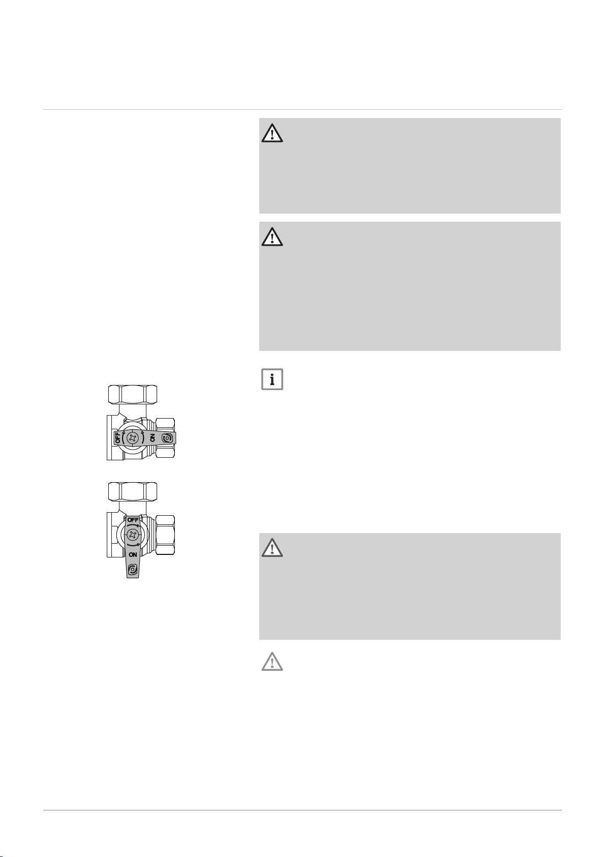
Fig.1 Taps ON and OFF
Note
If a water or gas leak occurs or is suspected, the boiler can be iso
lated at the inlet valves by turning their taps through 90° (1/4 turn)
downwards.
A ON
B OFF
For advice please contact your Installer, Annual Service Provider
or Baxi Customer Support - The Service Division of Baxi. You can
contact Baxi Customer Support on telephone number 0344 871
1545.
When contacting Baxi Customer Support it will be useful to have
the "Benchmark Checklist " at the back of the Installation & Serv
ice Manual to hand as it includes details relevant to the boiler and
installation.
Warning
Do not touch flue/chimney pipes. Depending on the settings of the
appliance, the temperature of flue/chimney pipes may exceed 60
°C.
Do not touch radiators for long periods. Depending on the settings
of the appliance, the temperature of radiators may reach 85 °C.
Take precautions with domestic hot water. Depending on the set
tings of the appliance, domestic hot water temperature may reach
65 °C.
Caution
Do not neglect to service the appliance. Contact a qualified pro
fessional or take out a maintenance contract for the annual servic
ing of the appliance.
Page 6

1 Safety
6 7661618 - 1 - 04072016
1.2 Recommendations
Caution
Only qualified professionals are authorised to work on the boiler
and the installation.
The appliance has an integral frost protection mode as long as
there is power to the boiler.
Note
Regularly check the water pressure in the system (recommended
pressure is 1.5 bar).
Keep the appliance accessible at all times.
Do not remove or cover the user information and serial number la
bels affixed to the boiler control flap. They must remain legible
throughout the lifetime of the boiler.
1.2.1
Baxi Heating UK Ltd is a licensed member of the Benchmark Scheme
which aims to improve the standards of installation and commissioning of
domestic heating and hot water systems in the UK and to encourage regu
lar servicing to optimise safety, efficiency and performance.
Benchmark is managed and promoted by Heating and Hotwater Industry
Council. For more information visit www.centralheating.co.uk
1.2.2
Please ensure that the installer has fully completed the Benchmark Check
list on the inside back pages of the installation instructions supplied with
the product and that you have signed it to say that you have received a full
and clear explanation of its operation. The installer is legally required to
complete a commissioning checklist as a means of complying with the ap
propriate Building Regulations (England and Wales).
All installations must be notified, by the installer, to Local Area Building
Control either directly or through a Competent Persons Scheme. A Build
ing Regulations Compliance Certificate will then be issued to the customer
who should, on receipt, write the Notification Number on the Benchmark
Checklist.
This product should be serviced annually to optimise its safety, efficiency
and performance. The service engineer should complete the relevant sec
tion of the Benchmark Service Record in the Installation & Service manual
after each service.
The completed Benchmark Checklist & proof of annual servicing (where
applicable) will be required in the event of any warranty work.
The Benchmark Scheme
Benchmark Commissioning Checklist
1.3
Liabilities
1.3.1 User's liability
To guarantee optimum operation of the system, you must abide by the fol
lowing instructions:
Read and follow the instructions given in the manuals provided with the
appliance.
Call on a qualified professional to carry out installation and initial com
missioning.
Get your installer to explain your installation to you.
Have the required inspections and maintenance carried out by a quali
fied installer.
Keep the instruction manuals in good condition close to the appliance.
Page 7

1 Safety
7661618 - 1 - 04072016 7
1.3.2 Installer's liability
The installer is responsible for the installation and initial commissioning of
the appliance. The installer must abide by the following instructions:
Read and follow the instructions given in the manuals provided with the
appliance.
Install the appliance in compliance with prevailing legislation and stand
ards.
Carry out initial commissioning and any checks necessary.
Explain the installation to the user.
If maintenance is necessary, warn the user of the obligation to check the
appliance and keep it in good working order.
Give all the instruction manuals to the user.
1.3.3 Manufacturer's liability
Our products are manufactured in compliance with the requirements of the
various Directives applicable. They are therefore delivered with the
marking and any documents necessary. In the interests of the quality of
our products, we strive constantly to improve them. We therefore reserve
the right to modify the specifications given in this document.
Our liability as manufacturer may not be invoked in the following cases:
Failure to abide by the instructions on installing the appliance.
Failure to abide by the instructions on using the appliance.
Faulty or insufficient maintenance of the appliance.
Page 8
2 About this manual
8 7661618 - 1 - 04072016
2 About this manual
2.1 General
Warning
Installation, repair and maintenance must only be carried out only
by a competent person.
All Gas Safe registered engineers carry an ID card with their licence num
ber and a photograph. You can check your engineer is registered by tele
phoning 0800 408 5500 or online at www.gassaferegister.co.uk
This manual is intended for the user of the Baxi Combi boiler. If the appli
ance is sold or transferred, or if the owner moves leaving the appliance
behind you should ensure that the manual is kept with the appliance for
consultation by the new owner and their installer.
The appliance is designed as a boiler for use in residential domestic envi
ronments on a governed meter supply only. The selection of this boiler is
entirely at the owner’s risk. If the appliance is used for purposes other than
or in excess of these specifications, the manufacturer will not accept any
liability for resulting loss, damage or injury.
The manufacturer will not accept any liability whatsoever for loss, damage
or injury arising as a result of failure to observe the instructions for use,
maintenance and installation of the appliance.
2.2 Additional documentation
2.3 Symbols used
Various timers, external controls, etc. are available as optional extras. Full
details are contained in the relevant sales literature.
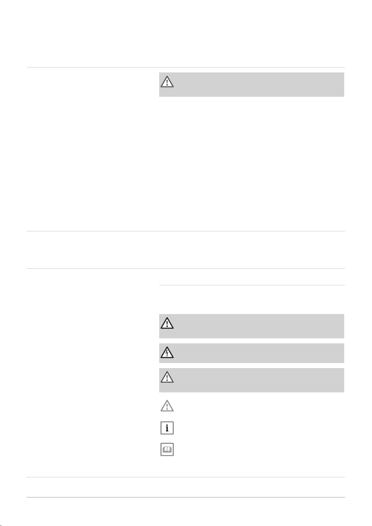
2.3.1 Symbols used in the manual
This manual uses various danger levels to draw attention to special in
structions. We do this to improve user safety, to prevent problems and to
guarantee correct operation of the appliance.
Danger
Risk of dangerous situations that may result in serious personal
injury.
Danger of electric shock
Risk of electric shock.
Warning
Risk of dangerous situations that may result in minor personal in
jury.
Caution
Risk of material damage.
Note
Please note: important information.
See
Reference to other manuals or pages in this manual.
2.4
Abbreviations/glossary
CH Central heating
Page 9

DHW Domestic hot water
7661618 - 1 - 04072016 9
PCU PCB for managing burner operation
Pnc Condensing output
SU Safety PCB
2 About this manual
Page 10
3 Technical specifications
10 7661618 - 1 - 04072016
3 Technical specifications
3.1 Homologations
3.1.1 Certifications
Tab.1 Certifications
CE certificate number 0085CQ0192
NOx class 5 (EN 15502)
Boiler type C13, C
33
3.2
Tab.2 General
Tab.3 Heating circuit specifications
Tab.4 Domestic water circuit specifications
Technical data
3.2.1
Baxi Combi 224 228 424 428
Gas council numbers 47–077–21 47–077–22 47–077–23 47–077–24
Baxi Combi 224 228 424 428
Maximum pressure bar 3 3 3 3
Minimum pressure bar 0.5 0.5 0.5 0.5
Heating circuit temperature °C 25/80 ± 5° 25/80 ± 5° 25/80 ± 5° 25/80 ± 5°
Baxi Combi 224 228 424 428
Maximum pressure bar 8.0 8.0 8.0 8.0
Dynamic minimum pressure bar 0.15 0.15 0.15 0.15
Minimum water flow l/min 2.0 2.0 2.0 2.0
Domestic water circuit tempera
ture
Specific flow rate (D) l/min 11.5 13.4 11.5 13.4
°C 35/60 ± 5° 35/60 ± 5° 35/60 ± 5° 35/60 ± 5°
Technical information
Note
Where low flow taps or fittings are intended to be used in the DHW system connected to the boiler,
it is strongly recommended that the DHW flow rate DOES NOT fall below 2.5 l/min. This will ensure
reliable operation of the DHW function.
Tab.5 Electrical specifications
Baxi Combi 224 228 424 428
Electrical power supply voltage V 230 230 230 230
Electrical power supply fre
quency
Nominal electrical power W 84 94 84 94
External fuse rating Amp 3A 3A 3A 3A
Hz 50 50 50 50
Page 11
1
2
3
4
5 6 7
8
700
279
395
PN-0000264
A
*
5.0
6
B*
285
700
3
95
PN-0000205
5.0
178
3 Technical specifications
7661618 - 1 - 04072016 11
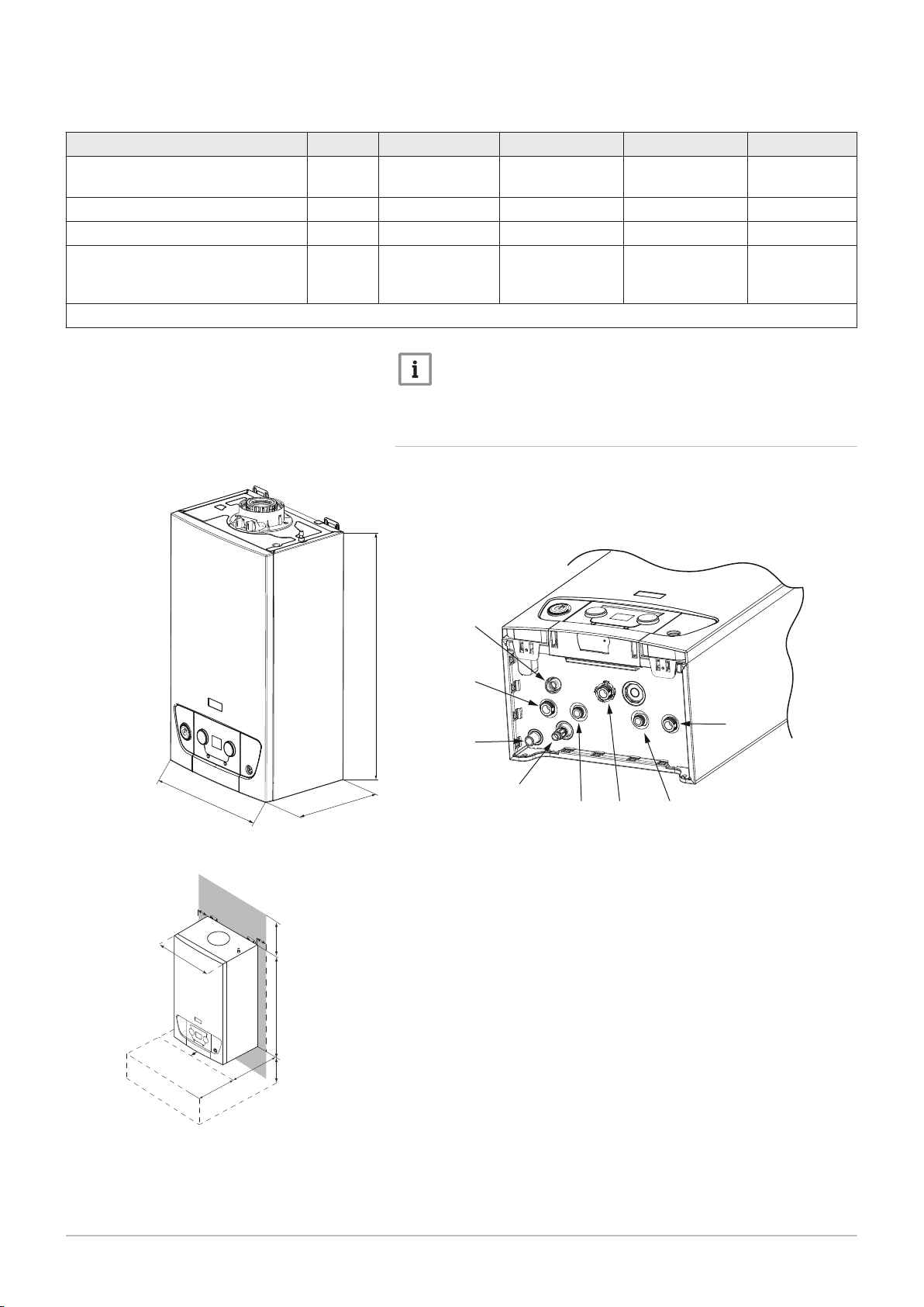
Tab.6 Other specifications
Baxi Combi 224 228 424 428
Degree of protection against humidi
IP IPX5D IPX5D IPX5D IPX5D
ty (EN 60529)
Net weight when empty/water load kg 26/28 26/28 26/28 26/28
Dimensions (height/width/depth) mm 700/395/279 700/395/279 700/395/279 700/395/279
Clearances (above/below casing)
front (for servicing)/(in operation)
side (left hand/right hand)
mm
mm
mm
178/250*
1000*/6
5/5
178/250*
1000*/6
5/5
178/250*
1000*/6
5/5
178/250*
1000*/6
5/5
* These are recommended dimensions. See fig. 3 for Minimum allowable clearances
Note
All data in this section are nominal values and subject to normal
production tolerances.
Fig.2
Fig.3
Dimensions and connections
Clearances
3.2.2
1
2
3
4
5
6
7
8
Dimensions and connections/clearances
Safety valve
Heating circuit water flow
Condensates discharge
Heating system/boiler drain tap
Domestic hot water outlet
Gas inlet
Mains cold water inlet
Heating circuit water return
A* Clearances below — 200mm minimum, 250mm recommended
B* Clearances in front — 450mm minimum, 1000mm recommended
The clearances shown in the diagram are minimum requirements to allow
for case removal, spanner access and air movement. These should be ob
served at all times and kept clear of obstructions.
Page 12

PN- 000 02 65
A
PN-0000266
PN-0000267
4 Description of the product
12 7661618 - 1 - 04072016
4 Description of the product
4.1 General description
Fig.4
Information label location
4.2 Operating principle
The Baxi Combi range of fully automatic gas fired wall hung condensing
combination boilers are room sealed and fan assisted, and will serve cen
tral heating and mains fed domestic hot water.
Tab.7 The boiler is set to give a maximum output of :-
24 model 24 kW DHW
21.8 kW CH Pnc (Condensing)
28 model 28 kW DHW
26.1 kW CH Pnc (Condensing)
The boiler is factory set for use only on Natural Gas (G20).
Priority is given to domestic hot water.
The boiler model, serial number and Gas Council number are also shown
on the information label. This is for user reference.
A
Information label
4.2.1 In operation
Whilst the boiler is in operation cooled flue gases are discharged through
the flue gas discharge pipe. This may appear as a cloud of steam which is
normal.
Condensed water is discharged from the boiler heat exchanger into a pipe
(the condensate drain). This pipe must never be altered or re-routed ex
cept by a qualified professional.
4.3
Fig.5 Control panel
Fig.6 Display screen
Control panel description
4.3.1
Description of the keys
Heating temperature control knob
Level access button: Information, Installer or Chimney Sweep
Manual reset button
Domestic hot water temperature control knob
4.3.2 Description of the display
Hour run meter
Malfunction
Maintenance
Reset necessary
Burner status
Heating mode
Outside temperature sensor
Domestic hot water mode
Page 13

4.4 Accessories and options
7661618 - 1 - 04072016 13
4 Description of the product
4.4.1 Optional accessories
The table below shows the accessories available for this boiler range.
Tab.8 Optional accessories
Part number Accessory
7658276 Baxi plug-in 24 hr mechanical timer combi - RH
7658523 Baxi plug-in 7 day digital timer combi - RH
7658781 Baxi plug-in receiver 24 hr RF programmable mech room
thermostat-combi
7658789 Baxi plug-in receiver 7 day RF digital programmable room
thermostat-combi
7212438 Baxi single channel wired programmable room thermostat
7212444 Baxi single channel wired timer
720971601 Baxi room thermostat
720330001 Baxi wired weather sensor
720648301 Multifit condensate & PRV combined pump
720644401 Multifit 1m condensate drain pipe 'trace heating' element
720664101 Multifit 2m Condensate drain pipe 'trace heating' element
720664201 Multifit 3m condensate drain pipe 'trace Heating' element
720664401 Multifit 5m condensate drain pipe 'trace heating' element
7659335 Baxi 200-400 stand off kit
5121379 Multifit remote secondary PRV kit
248221 Multifit filling loop (Not required for 424 and 428 models)
For Flue Accessories (elbows, extensions, clamps etc.) refer to the Flue
Installation Guide supplied in the literature pack.
Any of the above MUST be fitted ONLY by a qualified competent person.
Further details can be found in the relevant sales literature and at
www.baxi.co.uk
Page 14

START
Make sure the gas
supply is turned ON
and check if other
gas appliances are
operating (e.g. fire,
cooker). If the
property has a
prepayment meter
ensure it has
sufficient credit.
NO
If no gas, consult
your supplier.
Is there electricity to the
boiler ? Is the display lit ?
Check electrical supply to
boiler is switched on.
NO
YES
Is the Burner Flame
showing.
Burner Flame
(Indicates burner
is on)
Boiler operating
satisfactorily.
NO
YES
YES
YES YES
YES
If it does
not reset
CONTACT YOUR
INSTALLER OR
SERVICE ENGINEER.
Press the RESET button on the
controller to restart the boiler
Are reset and triangle symbols
illuminated or flashing?
Is the telephone symbol
illuminated or flashing?
OR
PN-0000229
5 Operation
14 7661618 - 1 - 04072016
5 Operation
5.1 Start-up
Fig.7 Start-up and checking
5.1.1 Operation checking procedure and basic fault identification
Page 15

Fig.8 Start up and checking (continued)
IMPORTANT: Where Low Flow Taps or Fittings are
intended to be used in the DHW system connected
to the boiler it is strongly recommended that the
DHW flow rate DOES NOT fall below 2.5 l/min.
This will ensure reliable operation of the DHW function.
Is the Timer ON and
calling for heat ?
Is the Room Thermostat
(if fitted) set high enough ?
12
1
2
3
4
5
6
7
8
9
10
11
Typical
examples
of external
timer
Ensure timer is set for
Central Heating ON (see
any instructions supplied
with timer)
NO
YES
YES
NO
15
10
5
20
25
15
10
5
20
25
Turn Room Thermostat
to maximum setting
(typical example shown)
CH ON
CH OFF
bar
0
1
2
3
4
Is the Central Heating
System Pressure
between 1.0 and 2.5 bar ?
Repressurise the system to
between 1.0 and 1.5 bar.
NO
YES
R
Error Code flashing between
E.02 and .07 indicating system
pressure below 0.5 bar.
YES
If you don’t know what you need to do
to get the boiler to light, or need help with
the system and controls, contact your
installer as soon as possible
R
PN-0000230
7661618 - 1 - 04072016 15
5 Operation
Page 16

1 2
3
PN-0000289
5 Operation
16 7661618 - 1 - 04072016
5.2 Use of the control panel
5.2.1 Control
Fig.9 Operating the controls
5.3
Shutdown
1. The controls are operated by the buttons and knobs shown.
1 Central heating water temperature control
2 Domestic Hot Water temperature control
3 Reset button
Isolate the mains power supply at the fused spur unit.
Isolate the gas supply at the boiler valve.
Protect the boiler from frost.
Note
The boiler is not protected against frost once it has been shut
down.
Note
If it is anticipated that the boiler will not be used for a long period
or the property is to be unoccupied it is recommended that the
system be drained if the electricity and gas supplies are to be
turned off. Your installer will be able to offer advice.
5.4
Frost protection
Where possible, draining the system should be avoided. If the system is to
be unused during winter months several precautions must be taken:
Any parts of the system that are in unheated areas of the dwelling fitted
with a device such as a pipe thermostat or frost thermostat.
Power must remain supplied to the boiler and controls.
Gas must remain supplied to the boiler.
The boiler pump will operate if the system temperature drops below 7°C. If
the temperature falls to 4°C the burner will ignite and remain lit until the
temperature reaches 10°C. At this temperature the burner will extinguish
but the pump will continue to operate for 15 minutes. This feature will pro
tect the boiler and to some extent adjacent parts of the system but addi
tional devices must be incorporated to guarantee frost protection.
Page 17

6 Settings
PN-0000291
PN-0000292
7661618 - 1 - 04072016 17
6.1 List of parameters
6 Settings
6.1.1 Reading out operating parameters
Pressing the button enables you to view information about how the boil
er is working.
1. Press this button for one second to view the operating mode (e.g. "t.
17" = purging in progress).
2. Press this button for one second again to view the operating substatus or the corresponding function that is active (e.g. "u.00" = boil
er in standby mode).
3. Press this button for one second again to view the operating temper
ature in the heating system: The symbol followed by the temper
ature in °C will flash.
4. Press this button for one second again to view the operating temper
ature in the domestic water system: The symbol followed by the
temperature in °C will flash.
5. Press this button for one second again to view the power level from
0 to 100: The symbol and the number relating to the level of oper
ating power will flash.
Press and hold the button for more than three seconds to exit this
menu.
6.2 Setting the parameters
Fig.10
Fig.11 Setting the domestic hot water tem
Setting the central heating
perature
6.2.1 Setting the central heating water temperature
Turn the central heating temperature setting button to adjust the central
heating water temperature. See Fig. 10.
Note
If the central heating water temperature set point is lower than
16°C without an outside temperature sensor, the heating is switch
ed off automatically. The heating starts up again only to ensure
frost protection if the outside temperature sensor shows a value of
less than 3°C.
6.2.2 Setting the domestic hot water temperature
Turn the domestic hot water temperature setting button to adjust the tem
perature. See Fig. 11.
Page 18

bar
0
1
2
3
4
bar
0
1
2
3
4
PN-0000259
7 Maintenance
18 7661618 - 1 - 04072016
7 Maintenance
7.1 General
The boiler does not require any special maintenance. However, the boiler
must be serviced annually in accordance with the Installation and Service
Manual and the relevant section of the Benchmark Service Record com
pleted in order to maintain the warranty.
Note
Taking out a maintenance contract is recommended.
Caution
Maintenance operations must be performed by a qualified compe
tent person.
Use only BAXI genuine spare parts.
The painted panels should be wiped with a damp cloth and then dried
completely. DO NOT USE ABRASIVE CLEANING AGENTS.
7.2
Maintenance instructions
Fig.12 Water pressure
The central heating system should be checked regularly. Proceed as fol
lows:
1. Check the water pressure in the central heating system.
Note
If the water pressure is lower than 0.7 bar, the system must be
topped up.
See
Re-pressurising the system.
Note
If the water pressure drops below 0.5 bar the boiler will not work.
2. Check radiators for leaks and (especially in damp areas) for rust.
3. Open and close the radiator valves several times a year to ensure
they can still be rotated.
Caution
Only a qualified installer may clean the inside of the boiler.
7.2.1 Re-pressurising the system
If the water pressure is too low, the system must be re-pressurised.
The normal operating water pressure is between 1 and 2 bar. If the pres
sure exceeds 3 bar the safety pressure valve will operate and a fault is in
dicated. Ensure that the temporary filling loop is disconnected. Contact
your installer.
It may be necessary to repressurise the system occasionally (when the
water pressure falls below 0.7). A filling device (the filling loop) will be fitted
on the system. This will be on the boiler itself, or on pipework near to the
boiler.
Page 19

PN-0000260
7 Maintenance
7661618 - 1 - 04072016 19
Fig.13 Filling loop (400 series only)
400 series boilers are supplied with a temporary filling loop as shown.
For 200 series boilers seek advice from your installer.
Note
If the water pressure requires regular re-pressurising a fault or
leak is indicated. Seek advice from your installer.
The temporary filling loop consists of two isolating taps and a separate fill
ing pipe with connection fittings.
Only when repressurising should the filling pipe be connected between the
two taps. Ensure that the nuts on the pipe ends are tightened onto the
taps.
1. Fully open one of the taps first, and then while watching the pres
sure gauge, carefully open the second tap.
Note
The system pressure is shown at all times on the pressure gauge
and can be viewed on the display when there is power to the boil
er.
2. When the figures on the display or needle on the pressure gauge in
dicate between 1 and 1.5 bar turn both taps off.
3. Disconnect the filling pipe from the taps (a small amount of water
may be present) and remove it. Keep the pipe in a safe place for fu
ture use.
4. If blanking caps are available fit them to the taps.
Note
Go to the "How to videos" section of the "Advice" page at
www.baxi.co.uk for further details.
5. When the correct pressure is restored the boiler will reset automati
cally.
Page 20

76
A
C
B
5
4
3
2
1
2
3
4
1
10
PN-0000225
7 Maintenance
20 7661618 - 1 - 04072016
7.3 Venting the installation
Fig.14 Venting the radiators
If any air is present in the appliance or system it must be removed in order
to prevent nuisance noises that may occur during heating or when drawing
off hot water. Proceed as follows:
1. Open the valves of all the radiators connected to the system.
2. Set the room thermostat to the highest possible temperature and
any timers to ‘ON’.
3. Wait until the radiators are warm.
4. Switch off the boiler.
5. Vent the radiators. Work from the lowest radiator in the property.
6. Open the bleed vent with the key, keeping a cloth pressed against
the vent.
7. Wait until water comes out of the bleed vent and then close.
Warning
The CH water in the radiators will still be hot.
8. Switch the boiler on.
9. After venting, check that the water pressure in the system is still ad
equate.
Note
If the air is difficult to remove, it is possible to manually de-aerate
the boiler and system using the control panel. Press and hold the
RESET button for approximately 5 seconds and release to start
the process. The display will show dAF briefly and then t.17 to in
dicate that the process has started. The de-aeration will last for
approximately 5 minutes then the control panel will revert to its
normal display.
Note
If the water pressure is lower than 0.7 bar, the water must be top
ped up. If necessary repressurise the system (recommended
pressure between 1 and 1.5 bar when cold).
10. Reset the room thermostat to the desired temperature.
Page 21

7.4 Draining the installation
AD-3000730-01
5
3
2
1
2
3
4
1
4
7661618 - 1 - 04072016 21
7 Maintenance
Fig.15 Draining the installation
It may be necessary to drain the central heating system if radiators need
to be replaced, if there is a major water leak or if there is a risk of freezing.
Proceed as follows:
1. Open the valves of all the radiators connected to the system.
2. Switch off the boiler's electrical connection.
3. Wait approximately ten minutes, until the radiators feel cold.
4. Connect a drain hose to the lowest draining point. Place the end of
the hose in a drain or at a place where drained pipe water will not
cause any damage.
5. Open the central heating system fill/drain valve. Drain the installa
tion.
Warning
The water may still be hot.
6. Close the drain valve when no more water comes from the draining
point.
Note
After draining the system, the concentration of corrosion inhibitor
and antifreeze agent may be extremely diluted - check with your
installer.
Page 22

PN-0000271
1
2
3
4
5
8 Troubleshooting
22 7661618 - 1 - 04072016
8 Troubleshooting
8.1 Error codes
Fig.16 Display errors
1
2
3
4
5
In the unlikely event of an error occurring the display will show either a
flashing triangle, or a flashing triangle with RESET. The display will also
flash and show the error code (see Error Code tables).
A warning triangle indicates a temporary fault. (3)
A warning triangle with RESET indicates a permanent fault. (4)
A temporary fault is indicated by an ‘H’ followed by a two-digit code num
ber (e.g. .02). This code flashes and alternates with a second two-digit
code (e.g. .06) to indicate the specific fault. (3)
A temporary fault prevents the boiler operating but will automatically reset
once the cause of the fault has been resolved.
Tab.9 Temporary error code descriptions
Control panel
Main display icons
Example of temporary error code (Low water pressure)
Example of permanent error code (Low water pressure)
Example of typical display after a successful RESET
Error code Description of fault
H01 00 Temporary loss of communication between the gas valve
and boiler PCB
H01 05 Maximum difference between flow and return temperature
reached
H01 08 Flow temperature increasing too quickly in heating mode
H01 14 Maximum flow temperature value reached
H01 18 No circulation of water in the system
H02 06 Low water pressure in the heating circuit
H03 02 Temporary loss of flame
A permanent fault ‘Lock out’ is indicated by an ‘E’ followed by a two-digit
code number (e.g. .02). This code flashes and alternates with a second
two-digit code (e.g. .07) to indicate the specific fault (4)
A permanent fault prevents the boiler operating and will not automatically
reset. Once the fault condition has been rectified the RESET button must
be pressed for at least 3 seconds to restart the boiler.
If the error cannot be reset, or it frequently re-occurs, please contact your
Installer, Annual Service Provider or Baxi Customer Support . You can
contact Baxi Customer Support on 0344 871 1545.
When contacting Baxi Customer Support it will be useful to have the
‘Benchmark Checklist’ at the back of the Installation & Service Manual to
hand as it includes details relevant to the boiler and installation.
Tab.10 Permanent error code descriptions
Error code Description of fault
E04 01
E04 02
E00 04
E00 05
E04 04
E04 05
E01 11
E04 13
E02 07 Low water pressure
Flow temperature sensor fault
Return temperature sensor fault
Flue temperature sensor fault
Fan fault
Page 23

8 Troubleshooting
7661618 - 1 - 04072016 23
Error code Description of fault
E01 17 No water circulation
E04 10 Ignition failure after 5 attempts
E01 04 Loss of flame detected 5 times in 24 hours
E04 00
E04 17
E04 08 Maximum safety temperature reached
E02 47 Connection with external device failed
E02 48 Configuration with external device failed
Note
If a different error code from those described in the error code ta
ble appears on the display contact Baxi Customer Support on
0344 871 1545.
Gas valve fault
8.2
Tab.11 Problems and solutions
Fault finding
Problem Possible causes Solution
Check that the boiler is being supplied with power.
Check fuses and the switches.
Check whether the gas isolation cock is properly
open.
If the property has a prepayment meter ensure it
has sufficient credit.
Increase the value with the CH temperature knob
or if a room thermostat is connected, increase the
temperature on the room thermostat.
system.
Check fuses and switches.
Check whether the gas isolation cock is properly
open.
If the property has a prepayment meter ensure it
has sufficient credit.
There is no domestic hot wa
ter.
The radiators are cold.
The boiler is not working.
The DHW function is switched off. Activate the DHW mode.
The water pressure is too low (< 0.5 bar). Re-pressurise the system.
Insufficient flow. Flow must be at least 2.5 litres per minute.
The temperature set point for the heating
is too low.
The heating mode is deactivated. Activate the heating mode.
The radiator valves are not open. Open the valves of all radiators connected to the
The boiler is not working. Check that the boiler is being supplied with power.
The water pressure is too low (< 0.5 bar). Re-pressurise the system.
Page 24

8 Troubleshooting
24 7661618 - 1 - 04072016
Problem Possible causes Solution
The temperature set point for the heating
is too low.
Increase the value with the CH temperature knob
or if a room thermostat is connected, increase the
temperature on the room thermostat.
No demand for heating. Ensure that timers & thermostats are calling for
heat.
No power supply. Check that the boiler is being supplied with power.
Check the fuses and switches.
The boiler is not working.
The water pressure is too low (< 0.5 bar). Re-pressurise the system.
The boiler is indicating an error. Press the Reset button.
Correct the error, if possible.
The gas pressure is too low. Check whether the gas isolation cock is fully open.
Open the gas isolation cock.
Condensate drain blocked. Check drain, especially any external runs in freez
ing temperatures.
If the boiler is not working also check section "Operation checking proce
dure and basic fault identification" or contact your Installer.
Page 25

9 Decommissioning
7661618 - 1 - 04072016 25
9.1 Decommissioning procedure
9 Decommissioning
Caution
Only qualified persons are authorised to work on the appliance
and system to decommission.
If your boiler needs to be decommissioned either temporarily or perma
nently the following should be performed:
1. Switch off the boiler.
2. Switch off the boiler’s electrical connection.
3. Close the gas isolation tap.
4. Drain the central heating system.
Seek the advice of your installer.
Page 26

10 Disposal
26 7661618 - 1 - 04072016
10 Disposal
10.1 Disposal and recycling
Caution
Removal and disposal of the boiler must be carried out by a quali
fied person in accordance with local and national regulations.
Page 27

11 Environmental
7661618 - 1 - 04072016 27
11.1 Energy saving
11 Environmental
Tips on saving energy:
Do not cover radiators. Do not hang curtains in front of radiators.
Install reflective panels behind the radiators to prevent heat loss.
Insulate the pipes in rooms that are not heated (cellars and lofts).
Install loft insulation & double glazing.
Use draught excluders where necessary.
Upgrade any older boiler external controls.
Turn down room thermostats by 1°.
Turn off radiators in rooms not in use.
Do not run hot (or cold) water pointlessly.
Fit a water-saving shower head to save up to 40 % energy.
Take showers rather than baths. A bath consumes twice as much water
and energy.
11.2
Room thermostats and settings
Various models of room thermostat are available. The thermostat type and
setting affect the total energy consumption.
A few tips:
A modulating thermostat in combination with thermostatic radiator valves
saves energy and offers considerable comfort. This combination gives
you flexibility with the temperatures. Do not fit thermostatic radiator
valves in the room in which the room thermostat is installed.
Completely closing and opening thermostatic valve radiators causes un
desirable temperature fluctuations. Open and close thermostatic valves
in small steps.
Lower the thermostat to around 20°C. This reduces heating costs and
energy consumption.
Lower the room thermostat temperature temporarily if opening windows
to air the rooms.
If you are using an ON/OFF type thermostat, reduce the water tempera
ture value in summer (e.g. 60°C in summer and 80°C in winter).
When setting an hourly programmable thermostat, consider days when
you are absent or on holiday. Electricity production and energy savings
reach their optimum level with a programmed and activated timer pro
gramme.
Page 28

12 Warranty
28 7661618 - 1 - 04072016
12 Warranty
12.1 General
To make sure your boiler warranty is activated and maintained, it is essen
tial that the:
1. Benchmark checklist is completed by your installer
2. Warranty is registered within 30 days
3. Boiler has an annual service
Please note that failure to adhere to terms and conditions will invalidate
your warranty.
12.2
Standard warranty terms and conditions
Warranty registration, service & repair
For full terms and conditions, visit www.baxi.co.uk/terms.
Benchmark checklist
The Benchmark Checklist will be completed by your installer and records
that the boiler has been installed and commissioned correctly. It can be
found at the back of the installation and service manual and should be
kept in a safe place for the life of the boiler. We will check that the Bench
mark Checklist has been completed on an in-warranty visit.
Ways to register your warranty
If your boiler is eligible for an extended warranty, your installer may regis
ter the product on your behalf and provide you with the relevant documen
tation. Please check with your installer.
Should this not be the case, you can register your warranty online at
www.baxi.co.uk/registration
To activate a standard two year warranty, please use one of the following
methods:
Freephone 0800 013 7989 or
Visit the website www.baxi.co.uk and go to Warranty Registration.
Annual service
A service must be completed every 12 months from the date of installation
to maintain your warranty.
This service must be completed by one of the following:
A Gas Safe registered installer/engineer
Baxi Customer Support; call us 0344 871 1545
Please make sure that your engineer has logged the service information at
the back of the installation and service manual. You will be asked for your
service history on any in-warranty repair visit.
If you experience a problem with your boiler
For any in or out of warranty repair, Baxi Customer Support is on hand to
help you. Call our award-winning team to arrange for one of our nation
wide team of Gas Safe registered engineers to visit.
If your product is in warranty, everything is free of charge, subject to our
warranty terms and conditions. If it is out of warranty, we can still help and
offer a range of options you can choose from to suit your needs.
Contact Baxi Customer Support 0344 871 1545
Opening hours
Monday - Friday, 8.00am - 6.00pm
Weekends and Bank Holidays, 8.30am - 2.00pm
Please note calls may be recorded for training and monitoring purposes.
When contacting Baxi Customer Support, please have the following infor
mation to hand:
Page 29

12 Warranty
7661618 - 1 - 04072016 29
Boiler serial number.
See
Section 4.1 for details.
Proof of purchase if you do not have the boiler serial
Please note that for in-warranty repairs, our engineers will ask to see your
service history record, completed Benchmark Checklist and details of your
installer. These can all be found in the Installation and Service manual.
Page 30

AAA
A
AAA
A
13 Appendix
30 7661618 - 1 - 04072016
13 Appendix
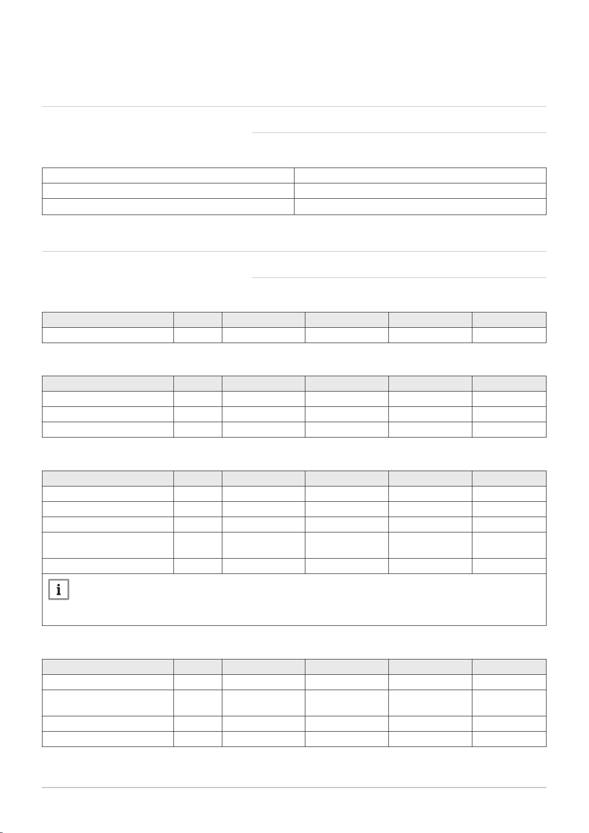
13.1 Product fiche - Combination boilers
Tab.12 Product fiche for combination boilers
Baxi Combi 224 228 424 428
Space heating - Temperature application Medium Medium Medium Medium
Water heating - Declared load profile XL XL XL XL
Seasonal space heating energy efficiency class
Water heating energy efficiency class
Rated heat output
Space heating - Annual energy consumption GJ 62 74 62 74
Water heating - Annual energy consumption
Seasonal space heating energy efficiency % 93 93 93 93
Water heating energy efficiency % 86 85 86 85
Sound power level LWA indoors dB 48 50 48 50
(1) Electricity
(2) Fuel
(Prated or Psup)
kW 20 24 20 24
kWh
GJ
(1)
(2)
33
17
33
17
33
17
33
17
See
For specific precautions about assembling, installing and main
taining: Safety, page 5
Page 31

13.2 Package fiche - boilers
AD-3000743-01
%
1
‘I’
2
%+
3
%( - ‘I’ ) x 0.1 = ±
4
%(‘III’ x + ‘IV’ x ) x 0.9 x ( /100) x = +
(1)
A* = 0.95, A = 0.91,
B = 0.86, C = 0.83,
D - G = 0.81
5
%( - ‘I’ ) x ‘II’ = +
6
%0.5 x 0.5 x = -
54
<30%
G F E D C B A A
+
A
++
A
+++
%+ (50 x ‘II’) =
7
7
%
from fi che of solar device
Solar contribution AND Supplementary heat pump
Solar contribution
The energy effi ciency of the package of products provided for in this fi che may not correspond to its actual energy effi ciency once installed
in a building, as this effi ciency is infl uenced by further factors such as heat loss in the distribution system and the dimensioning of the
products in relation to building size and characteristics.
Boiler and supplementary heat pump installed with low temperature heat emitters at 35°C ?
Seasonal space heating energy effi ciency class of package
Seasonal space heating energy effi ciency of package
OR
Seasonal space heating energy effi ciency (in %)
Supplementary heat pump
Tank rating
Collector effi ciency (in
%)
Tank volume (in m³) Collector size (in m²)
Seasonal space heating energy effi ciency (in %)
Supplementary boiler
Class I = 1%, Class II = 2%, Class III = 1.5%,
Class IV = 2%, Class V = 3%, Class VI = 4%,
Class VII = 3.5%, Class VIII = 5%
Temperature control
Seasonal space heating energy effi ciency of boiler
(1) If tank rating is above A, use 0.95
select smaller value
from fi che of heat pump
from fi che of heat pump
from fi che of boiler
from fi che of temperature control
7661618 - 1 - 04072016 31
Fig.17 Package fiche for boilers indicating the space heating energy efficiency of the package
13 Appendix
I The value of the seasonal space heating energy efficiency of the
preferential space heater, expressed in %.
Page 32

13 Appendix
32 7661618 - 1 - 04072016
II The factor for weighting the heat output of preferential and supple
mentary heaters of a package as set out in the following table.
III The value of the mathematical expression: 294/(11 · Prated),
whereby ‘Prated’ is related to the preferential space heater.
IV The value of the mathematical expression 115/(11 · Prated),
whereby ‘Prated’ is related to the preferential space heater.
Tab.13 Weighting of boilers
Psup / (Prated + Psup)
(1)(2)
II, package without hot water storage tank II, package with hot water storage tank
0 0 0
0.1 0.3 0.37
0.2 0.55 0.70
0.3 0.75 0.85
0.4 0.85 0.94
0.5 0.95 0.98
0.6 0.98 1.00
≥ 0.7 1.00 1.00
(1) The intermediate values are calculated by linear interpolation between the two adjacent values.
(2) Prated is related to the preferential space heater or combination heater.
Tab.14 Package efficiency
Baxi Combi 224 228 424 428
Temperature control X %
Temperature control Y %
Page 33

AD-3000747-01
%
1
‘I’
2
%(1.1 x ‘I’ - 10%) x ‘II’ - - ‘I’ = +
‘III’
<28%
XXL
XL
L
M
G F E D C B A A
+
A
++
A
+++
3
%
%+ 0.4 x =
23
%- 0.2 x =
23
The energy effi ciency of the package of products provided for in this fi che may not correspond to its actual energy effi ciency once installed
in a building, as this effi ciency is infl uenced by further factors such as heat loss in the distribution system and the dimensioning of the
products in relation to building size and characteristics.
Water heating energy effi ciency class of package under average climate
Water heating energy effi ciency of package under average climate
Auxiliary electricity
Solar contribution
Water heating energy effi ciency of combination heater
from fi che of solar device
Colder:
Warmer:
Water heating energy effi ciency under colder and warmer climate conditions
Declared load profi le:
13 Appendix
7661618 - 1 - 04072016 33
13.3 Package fiche - Combination heaters (boiler or heat pumps)
Fig.18 Package fiche for combination heaters (boilers or heat pumps) indicating the water heating energy efficiency of the
package
I The value of the water heating energy efficiency of the combination
heater, expressed in %.
II The value of the mathematical expression (220 · Q
where Q
15 and Q
is taken from Regulation EU 811/2013, Annex VII Table
ref
nonsol
clared load profile M, L, XL or XXL of the combination heater.
III The value of the mathematical expression (Q
expressed in %, where Q
solar device and Q
ble 15 for the declared load profile M, L, XL or XXL.
from the product fiche of the solar device for the de
is taken from the product fiche of the
aux
from Regulation EU 811/2013, Annex VII Ta
ref
)/Q
ref
· 2,5)/(220 · Q
aux
nonsol
,
),
ref
Page 34

13 Appendix
34 7661618 - 1 - 04072016
Page 35

© Copyright
All technical and technological information contained in these technical instructions, as well as any drawings and technical de
scriptions supplied, remain our property and shall not be multiplied without our prior consent in writing. Subject to alterations.
Page 36

Baxi Customer Support
0344 871 1545
Opening hours
Monday - Friday, 8.00am-6.00pm
Weekends and Bank Holidays, 8.30am-2.00pm
Please note calls may be recorded for training and monitoring purposes
baxi.co.uk
Register now to activate your warranty:
www.baxi.co.uk/registration
For the warranty to be maintained, please make sure...
Benchmark checklist is completed
Warranty is registered within 30 days
The boiler has an annual service
1
2
3
For full terms and conditions, visit www.baxi.co.uk/terms. Failure to adhere to
terms and conditions will void your manufacturer’s warranty.
Baxi
Brooks House,
Coventry Road,
Warwick, CV34 4LL
Please ensure the boiler is installed in accordance with these installation
instructions and that you adhere to the Building Regulations.
e&oe
All descriptions and illustrations provided in this document have been
carefully prepared but we reserve the right to make changes and
improvements in our products which may affect the accuracy of the
information contained in this leaflet. All goods are sold subject to our
standard Conditions of Sale which are available on request.
7661618 - 1 - 04072016
 Loading...