

Page 1

IT
RUS
FR
ENG
BPI-Eco
Page 2

Page 3

BPI-ECO - ITALIANO
INDICE
1 AVVERTENZE GENERALI . . . . . . . . . . . . . . . . . . . . . . . . . . . . . . . . . . . . . . . . . . . . . . . . . . . . . . . . . . . . . . . . . . . . . . . . . . . . . . 4
2 FORNITURA . . . . . . . . . . . . . . . . . . . . . . . . . . . . . . . . . . . . . . . . . . . . . . . . . . . . . . . . . . . . . . . . . . . . . . . . . . . . . . . . . . . . . . . . . 4
3 CARATTERISTICHE TECNICHE DIMENSIONALI . . . . . . . . . . . . . . . . . . . . . . . . . . . . . . . . . . . . . . . . . . . . . . . . . . . . . . . . . 5
3.1 DESCRIZIONE
3.2 DIMENSIONI D’INGOMBRO
3.3 DATI TECNICI
3.4 PERDITE DI CARICO
4 INSTALLAZIONE . . . . . . . . . . . . . . . . . . . . . . . . . . . . . . . . . . . . . . . . . . . . . . . . . . . . . . . . . . . . . . . . . . . . . . . . . . . . . . . . . . . . . 6
4.1 LOCALE CALDAIA
4.2 ALLACCIAMENTO ALLA CANNA FUMARIA
4.3 ALLACCIAMENTO IMPIANTO
4.4 MONTAGGIO ACCESSORI
4.5 MONTAGGIO MANTELLO
4.6 REGOLATORE DI TIRAGGIO
4.7 SCAMBIATORE TERMICO DI SICUREZZA
4.8 SCHEMI DI COLLEGAMENTO IDRAULICO
5 USO E MANUTENZIONE . . . . . . . . . . . . . . . . . . . . . . . . . . . . . . . . . . . . . . . . . . . . . . . . . . . . . . . . . . . . . . . . . . . . . . . . . . . . . . 10
5.1 CONTROLLI PRELIMINARI ALL’ACCENSIONE
5.2 TERMOMETRO CALDAIA
5.3 REGOLAZIONE ARIA
5.4 PULIZIA
5.5 MANUTENZIONE
5.6 SMALTIMENTO DELL’APPARECCHIO (DIRETTIVA EUROPEA 2002/96/EC)
Page 4
4
1 AVVERTENZE GENERALI
Il manuale istruzioni costituisce parte integrante del prodotto e dovrà essere consegnato all’utilizzatore. Leggere attentamente
le avvertenze contenute nel manuale
riguardanti l’installazione, l’uso e la manutenzione dell’apparecchio. Conservare con
cura il manuale per ogni ulteriore consultazione.
L’installazione dovrà essere effettuata da
personale qualificato in ottemperanza alle
norme vigenti seguendo le istruzioni del
costruttore. Un’errata installazione può
causare danni a persone o cose per le quali
l’azienda non è responsabile.
Assicurasi dell’integrità del prodotto. In
caso di dubbi non utilizzare l’apparecchio e
rivolgersi al fornitore.
Gli elementi dell’imballaggio devono essere
smaltiti in ottemperanza alla normativa
vigente.
Prima di effettuare qualsiasi operazione di
manutenzione dell’apparecchio disinserire
l’alimentazione elettrica agendo sull’interruttore dell’impianto.
In caso di guasto o cattivo funzionamento
disattivare l’apparecchio astenendosi da
qualsiasi tentativo di riparazione o interven-
to diretto. Rivolgersi esclusivamente a personale tecnico qualificato. L’eventuale riparazione dovrà avvenire solamente utilizzando ricambi originali.
La mancata osservazione di quanto sopra
riportato può compromettere l’integrità
dell’impianto o dei singoli componenti, causando un potenziale pericolo per la sicurezza dell’utente di cui l’azienda non assume
nessuna responsabilità.
È necessario eseguire la manutenzione
dell'apparecchio e del condotto fumi almeno una volta l'anno.
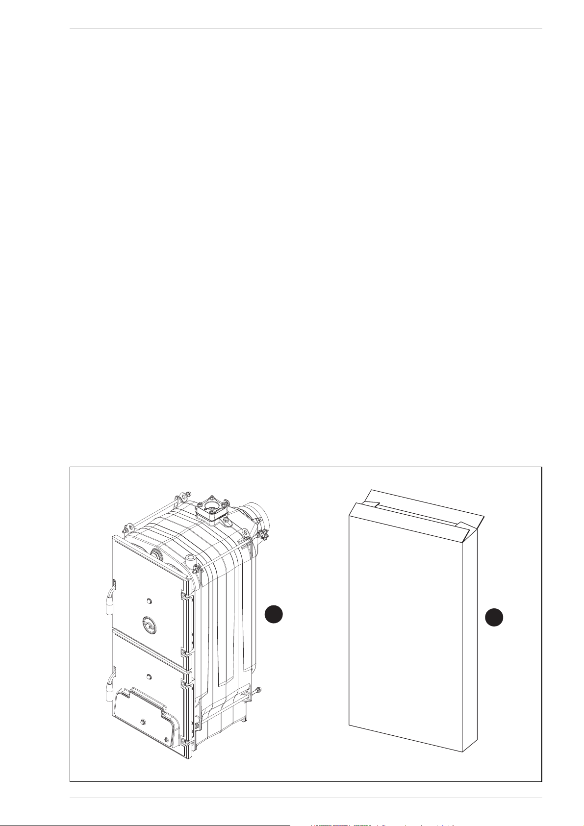
2 FORNITURA
La caldaia, come indicato in fig. 1, viene fornita
in due colli separati:
– Corpo caldaia in ghisa completo di came-
ra fumo con serranda di regolazione,
bacinella raccolta cenere e regolatore
termostatico di tiraggio. Un sacchetto
contenente: 2 maniglie per le porte, una
vite con pomello in bachilite per la regolazione manuale della serranda immissione aria, una molla di contatto per il bulbo
del termometro e la leva M6 da fissare
alla serranda immissione aria. “Certifica-
to di Collaudo” e “Dichiarazione di conformità” da conservare con i documenti
della caldaia.
– Imballo cartone con mantello, termome-
tro e kit documenti. Il kit documenti comprende: manuale istruzioni, certificato di
garanzia, targhetta DATI TECNICI CALDAIA, libretto di impianto (< 35 KW) o di
centrale (> 35 kW) e modulo etichette
da applicare sulla dichiarazione di conformità.
ATTENZIONE: La targhetta DATI TECNICI
CALDAIA inserita nel kit documenti è adesiva e dovrà essere applicata ad un fianco
del mantello a cura dell’installatore.
Il numero di matricola del corpo di ghisa è
riportato su una targhetta rivettata sulla
parte alta posteriore del corpo.
Per facilitare il trasporto, il carico e lo
scarico della caldaia, sono previsti, sulla
parte superiore della stessa, idonei ganci
per il sollevamento.
Fig. 1
1
2
Page 5

3 CARATTERISTICHE TECNICHE E DIMENSIONALI
3.3 DATI TECNICI
3.1 DESCRIZIONE
La legna è una fonte di energia alternativa
e preziosa, è quindi fondamentale utilizzarla
nel modo migliore adottando per la combustione adeguate tecnologie.
Le caldaie in ghisa a legna a combustione
tradizionale BPI-Eco sono progettate per
garantire la massima resa termica ottimizzando il tiraggio.
Le caldaie sono conformi alla Direttiva PED
97/23/CEE e Norma EN 303-5.
3.2 DIMENSIONI D’INGOMBRO (fig. 2)
Fig. 2
M Mandata impianto 2” (UNI-ISO 7/1)
R Ritorno impianto 2” (UNI-ISO 7/1)
S Scarico caldaia 1/2” (UNI-ISO 7/1)
Fig. 3
123 4
0
5
10
15
20
Portata m3/h
∆p mbar
1.2 50
1.450
1.650
5
1.550
1.350
25
30
35
3.4 PERDITE DI CARICO (fig. 3)
BPI-Eco 1.250 1.350 1.450 1.550 1.650
Potenza termica a carbone kW 23,0 34,0 45,0 56,0 67,0
Potenza massima a legna kW 20,0 30,0 40,0 49,0 58,0
Potenza termica a legna kW 14,0 20,5 27,5 34,0 40,0
Classe di rendimento EN 303-5 11111
Durata di una carica a carbone h
≥
4
≥
4
≥
4
≥
4
≥
4
Durata di una carica a legna h
≥
2
≥
2
≥
2
≥
2
≥
2
Volume di carica dm
3
42,7 66,4 90,2 113,9 137,7
Depressione minima al camino mbar 0,08 0,10 0,12 0,13 0,15
Dimensioni
P (profondità) mm 425 575 725 875 1025
L (profondità camera combustione) mm 346 496 646 796 946
Elementi di ghisa n° 3 4 5 6 7
Temperatura max esercizio °C 95 95 95 95 95
Temperatura minina acqua ritorno impianto °C 50 50 50 50 50
Pressione max esercizio bar 4 4 4 4 4
Pressione di collaudo bar 6 6 6 6 6
Capacità caldaia l30 39 48 57 66
Peso kg 226 288 350 412 474
5
347
392
500
211
ø 147
10 01
P
L
M
825
R
19 2
=
S
15 5
176
=
1023
Page 6

6
4.1 LOCALE CALDAIA
Verificare che il locale abbia requisiti e
caratteristiche rispondenti alle norme
vigenti. È inoltre necessario che nel locale
affluisca almeno tanta aria quanta ne viene
richiesta per una regolare combustione.
È quindi necessario praticare, nelle pareti
del locale, delle aperture che rispondano ai
seguenti requisiti:
– Avere una sezione libera di almeno 6
cm2per ogni 1,163 kW (1000 kcal/h).
La sezione minima dell’apertura non
deve essere comunque inferiore ai 100
cm2. La sezione può essere inoltre calcolata utilizzando la seguente relazione:
dove “S” è espresso in cm2, “Q” in kcal/h
– L’apertura deve essere situata nella
parte bassa di una parete esterna, preferibilmente opposta a quella in cui si
trova l’evacuazione dei gas combusti.
4.1.1 Posizionamento
in centrale termica (fig. 4)
La caldaia deve essere installata su un
basamento non combustibile. Ad installazione avvenuta la caldaia dovrà risultare orizzontale e ben stabile onde ridurre le eventuali vibrazioni e la rumorosità. Dietro alla
caldaia si dovrà comunque lasciare uno
spazio libero, tale da permettere l'apertura
e la manutenzione del ventilatore.
ATTENZIONE: Le distanze minime indicate
in figura sono vincolanti e sono solo per i
modelli aventi potenzialità superiore a 35
kW.
4.2 ALLACCIAMENTO ALLA
CANNA FUMARIA
Una canna fumaria deve rispondere ai
seguenti requisiti:
– Deve essere di materiale impermeabile e
resistente alla temperatura dei fumi e
relative condensazioni.
– Deve essere di sufficiente resistenza
meccanica e di debole conduttività termica.
– Deve essere perfettamente a tenuta,
per evitare il raffreddamento della canna
fumaria stessa.
– Deve avere un andamento il più possibile
verticale e la parte terminale deve avere
un’aspiratore statico che assicura una
efficiente e costante evacuazione dei
prodotti della combustione.
– Allo scopo di evitare che il vento possa
creare attorno al comignolo delle zone di
pressione tale da prevalere sulla forza
ascensionale dei gas combusti, è necessario che l’orifizio di scarico sovrasti di
almeno 0,4 metri qualsiasi struttura
adiacente al camino stesso (compreso il
colmo del tetto) distante meno di 8
metri.
– La canna fumaria deve avere un diame-
tro non inferiore a quello di raccordo caldaia; per canne fumarie con sezione quadrata o rettangolare la sezione interna
deve essere maggiorata del 10% rispetto a quella del raccordo caldaia.
– La sezione utile della canna fumaria può
essere ricavata dalla seguente relazione:
S sezione risultante in cm
2
K coefficiente in riduzione:
– 0,045 per legna
– 0,030 per carbone
P potenza della caldaia in kcal/h
H altezza del camino in metri misurata
dall'asse della fiamma allo scarico
del camino nell'atmosfera. Nel di-
mensionamento della canna fumaria
si deve tener conto dell'altezza effet-
tiva del camino in metri, misurata
dall'asse della fiamma alla sommità,
diminuita di:
– 0,50 m per ogni cambiamento di
direzione del condotto di raccordo
tra caldaia e canna fumaria;
– 1,00 m per ogni metro di sviluppo
orizzontale del raccordo stesso.
4.3 ALLACCIAMENTO IMPIANTO
È opportuno che i collegamenti siano facilmente disconnettibili a mezzo bocchettoni
con raccordi girevoli. È sempre consigliabile
montare delle idonee saracinesche di intercettazione sulle tubazioni impianto riscaldamento.
ATTENZIONE: E’ obbligatorio il montaggio
della valvola di sicurezza sull’impianto non
inclusa nella fornitura.
4.3.1 Riempimento impianto
Prima di procedere al collegamento della
caldaia è buona norma far circolare
acqua nelle tubazioni per eliminare gli
eventuali corpi estranei che comprometterebbero la buona funzionalità dell’apparecchio.
Il riempiemento va eseguito lentamente per
dare modo alle bolle d’aria di uscire attraverso gli opportuni sfoghi, posti sull’impianto di riscaldamento. In impianti di riscaldamento a circuito chiuso la pressione di caricamento a freddo dell’impianto e la pressione di pregonfiaggio del vaso di espansione
dovranno corrispondere, o comunque non
essere inferiori, all’altezza della colonna
statica dell’impianto (ad esempio, per una
colonna statica di 5 metri, la pressione di
precarica del vaso e la pressione di caricamento dell’impianto dovranno corrispondere almeno al valore minimo di 0,5 bar).
4.3.2 Caratteristiche
dell’acqua di alimentazione
L’acqua di alimentazione del circuito riscaldamento deve essere trattata in conformità alla Norma UNI-CTI 8065.
È opportuno ricordare che anche piccole
incrostazioni di qualche millimetro di spessore provocano, a causa della loro bassa
conduttività termica, un notevole surriscaldamento delle pareti della caldaia con conseguenti gravi inconvenienti.
È ASSOLUTAMENTE INDISPENSABILE IL
TRATTAMENTO DELL’ACQUA UTILIZZATA
4 INSTALLAZIONE
Q
S=
10 0
P
S=K
√H
Fig. 4
600
BAXI
1000
600
600
1000
1300
Page 7

PER L’IMPIANTO DI RISCALDAMENTO NEI
SEGUENTI CASI:
– Impianti molto estesi (con elevati conte-
nuti d’acqua).
– Frequenti immissioni d’acqua di reinte-
gro nell’impianto.
– Nel caso si rendesse necessario lo svuo-
tamento parziale o totale dell’impianto.
4.4 MONTAGGIO ACCESSORI
(fig. 5 - fig. 5/a)
Le maniglie di chiusura porte e la vite con
pomello regolazione serranda aria sono fornite a parte in quanto potrebbero rovinarsi
durante il trasporto. Sia le maniglie che la
vite con pomello sono contenute in sacchetti di nylon inseriti all’interno della bacinella raccolta ceneri.
Per il montaggio delle maniglie procedere
nel modo seguente (fig. 5):
– Prendere una maniglia (1), infilarla nella
feritoia della porta di carico (2) ed inserire il rullino (3) nel foro della maniglia;
bloccare la maniglia inserendo la coppiglia elastica (4).
– Eseguire la stessa operazione per la
maniglia della porta del cenerario.
Per il montaggio della vite con pomello pro-
cedere nel modo seguente (fig. 5/a):
– Togliere la vite M8 x 60 che fissa la ser-
randa d’immissione aria alla porta del
cenerario ed avvitare la vite con pomello
in bachilite (1) fornita nella confezione.
Porre all’estremità della vite M10 il dado
cieco con calotta (2).
– Fissare la leva M6 (3) alla serranda del-
l’aria ponendola in orizzontale verso
destra. La leva ha all’estremità un foro
sul quale verrà poi collegata la catenella
del regolatore termostatico.
4.5 MONTAGGIO MANTELLO
(fig. 6)
Dal lato posteriore della caldaia, sui due
Fig. 6
7
LEGENDA
1 Maniglia
2 Porta di carico
3 Rullino
4 Coppiglia elastica
Fig. 5
LEGENDA
1 Vite con pomello M10 x 70
2 Dado cieco con calotta
3 Leva M6
Fig. 5/a
8
1
2
3
7
4
6
1
5
2
Page 8

8
tiranti superiori, sono avvitati tre dadi: il
secondo ed il terzo dado servono a posizionare correttamente i fianchi del mantello.
Nei tiranti inferiori sia dalla parte anteriore
che nella parte posteriore della caldaia,
sono avvitati due dadi di cui uno per bloccare le staffe supporto fianchi. Il montaggio
dei componenti del mantello va eseguito nel
seguente modo:
– Svitare di alcuni giri il secondo o il terzo
dado di ciascun tirante.
– Agganciare il fianco sinistro (1) sul tiran-
te inferiore e superiore della caldaia e
regolare la posizione del dado e contro-
dado del tirante superiore.
– Bloccare il fianco serrando i controdadi.
– Per montare il fianco destro (2) procede-
re nella stessa maniera.
– Agganciare il pannello posteriore (4)
inserendo le linguette nelle feritoie rica-
vate su ciascun fianco e bloccarlo ai fina-
chi con sei viti autofilettanti.
– Il deflettore di protezione (5) è fissato al
pannello frontale (6) con tre viti autofilet-
tanti. Tra i due elementi inserire la lana di
roccia.
– Fissare il pannello frontale (6) per mezzo
di piolini a pressione.
– Svolgere il capillare del termometro (7) e
introdurlo nella guaina della testata
posteriore, inserendo la molletta di con-
tatto che dovrà essere tagliata a circa
45 mm. Il cavo del termometro deve
essere posto sopra l’isolante e non a
diretto contatto con il corpo in ghisa.
– Fissare il coperchio (8) ai fianchi della
caldaia per mezzo di piolini a pressione.
- Appicare la targhetta adesiva DATI TEC-
NICI CALDAIA al fianco destro o sinistro
del mantello in modo che sia leggibile ad
apparecchio installato.
NOTA: Conservare con i documenti della
caldaia il “Certificato di Collaudo” e la
“Dichiarazione di conformità” inseriti nella
camera di combustione.
4.6 REGOLATOREDI TIRAGGIO
A FUNZIONAMENTO
TERMOSTATICO
Tramite il regolatore di tiraggio a funzionamento termostatico si può ottenere una
variabilità continua dell'aria introdotta nel
focolare della caldaia.
Questo regolatore, tramite una catenella di
collegamento, agisce sulla portina inferiore
di immissione dell'aria primaria.
Al raggiungimento della temperatura fissata, il regolatore provvede automaticamente
a diminuire l'apertura della portina di
immissione dell'aria in modo da rallentare
la combustione ed evitare surriscaldamenti. Allo scopo di ottimizzare la combustione
sulla porta superiore di caricamento e
posta una portina rotonda di regolazione
che distribuisce l'aria secondaria in controcorrente rispetto al tragitto dei prodotti
della combustione.
Questo processo, che incrementa ulterior-
mente il rendimento, consente uno sfruttamento più efficace del combustibile. Le caldaie possono montare indifferentemente
due tipi di regolatori termostatici.
4.6.1 Regolatore “THERMOMAT RT-C”
(fig. 7)
Il regolatore “Thermomat” è dotato di
manopola in resina termoindurente con
campo di regolazione da 30 a 100 °C (fig.
7). Avvitare il regolatore in posizione verti-
cale sul foro 3/4” della testata anteriore
con la sede della leva della catenella verso il
fronte della caldaia. La leva con catenella
deve essere introdotta nel supporto del
regolatore dopo aver montato il mantello
ed aver tolto il fermo di plastica. Se si sfila
lo snodo che fissa la leva con catenella fare
attenzione a rimontarlo nella medesima
posizione. Dopo aver posizionato la manopola su 60°C bloccare la leva con catenella
in posizione leggermente inclinata verso il
basso in modo che la catenella venga a trovarsi in asse con l’attacco della serranda
aria. Per la regolazione del “Thermomat”,
che consiste essenzialmente nella determinazione della lunghezza della catenella, procedere nel seguente modo:
– Posizionare la manopola a 60 °C.
– Accendere la caldaia con la serranda
immissione aria aperta.
– Al raggiungimento della temperatura di
60 °C dell’acqua di caldaia, fissare la
catena sulla leva della serranda immissione aria facendo in modo che questa
presenti una apertura di circa 1 mm.
–
A questo punto il regolatore risulta tarato
ed è possibile scegliere la temperatura di
lavoro desiderata ruotando la manopola.
4.6.2 Regolatore “REGULUS RT2”
(fig. 8)
Il campo di regolazione è compreso tra 30
e 90°C (fig. 8). Per il montaggio e la messa
in funzione seguire le stesse istruzioni del
regolatore “Thermomat”.
4.7 SCAMBIATORE TERMICO
DI SICUREZZA
Lo scambiatore termico di sicurezza viene
fornito a richiesta in un kit:
- cod. 8105200 per BPI.Eco
1.250/1.350/1.450
- cod. 8105201 per BPI-Eco 1.550/1.650.
Il kit è da utilizzare su impianti a vaso espansione chiuso e di potenza inferiore a 35
kW. La sua funzione è di raffreddare la caldaia in caso di sovratemperatura mediante
una valvola di scarico termico collegata
idraulicamente all’ingresso dello scambiatore. Prevedere, in corrispondenza dell’uscita
dello scambiatore, un tubo di scolo con
imbuto ed un sifone che conducano ad uno
scarico adeguato. Lo scarico deve essere
controllabile a vista.
ATTENZIONE: In assenza di tale precauzione, un eventuale intervento della valvola di scarico termico può causare danni a
persone, animali e cose, nei confronti dei
quali il costruttore non può essere considerato responsabile. Prima della messa in
funzione della caldaia assicurarsi che sia
garantita la portata d’acqua alla valvola
di scarico termico.
Fig. 8
Regolatore “REGULUS RT2”
Fig. 7
Regolatore “THERMOMAT RT-C”
Page 9
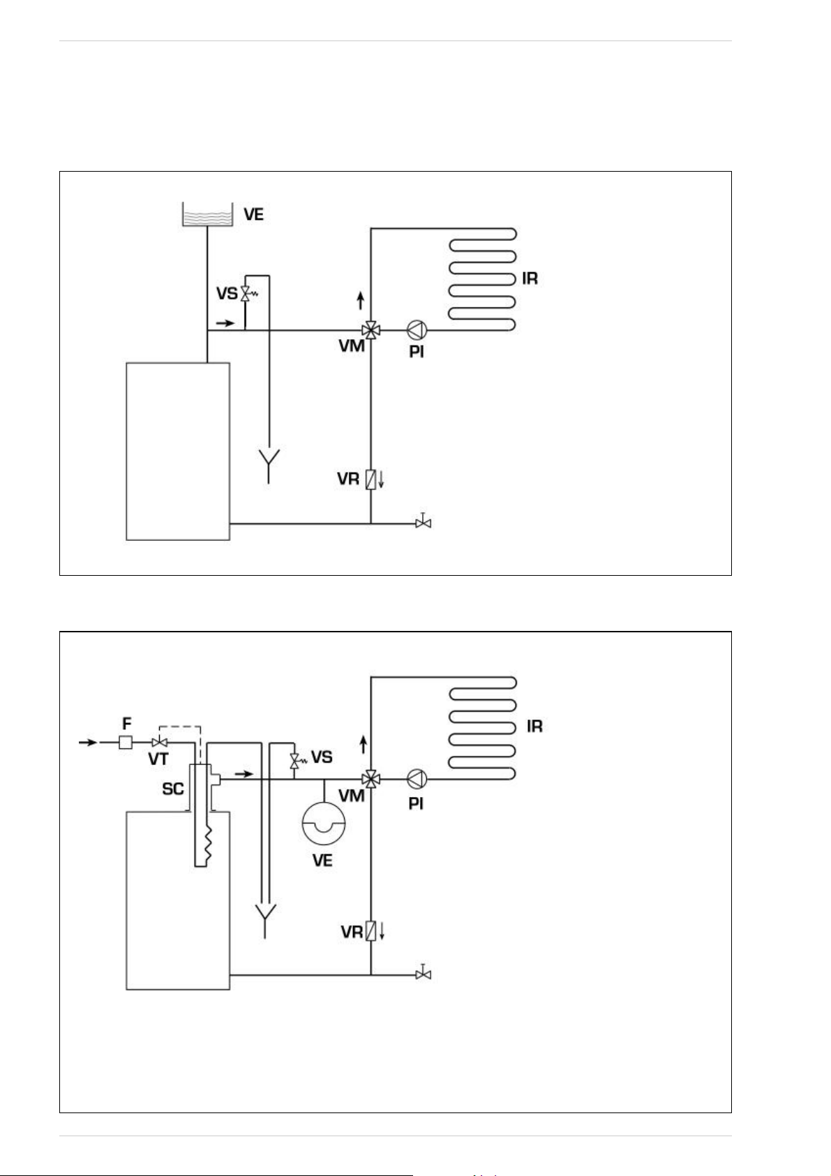
4.8 SCHEMI DI COLLEGAMENTO IDRAULICO
4.8.1 Impianto a vaso espansione aperto (fig. 9)
Fig. 9
LEGENDA
VE Vaso espansione aperto
VS Valvola sicurezza impianto 3 BAR - 1/2”
VM Valvola miscelatrice
VR Valvola di ritegno
PI Pompa impianto
IR Impianto di riscaldamento
4.8.2 Impianto a vaso espansione chiuso e scambiatore di sicurezza con valvola termostatica (fig. 10)
Fig. 10
LEGENDA
VE Vaso espansione
VS Valvola sicurezza impianto 3 BAR - 1/2”
VM Valvola miscelatrice
VR Valvola di ritegno
PI Pompa impianto
IR Impianto di riscaldamento
VT Valvola termostatica
SC Scambiatore di sicurezza
F Filtro
ATTENZIONE: Lo scambiatore di sicurezza (SC)
viene fornito a richiesta in un kit cod. 8105200/01.
Temperatura acqua alimentazione scambiatore di
sicurezza: 10°C.
Pressione acqua alimentazione scambiatore di sicurezza: 2 bar.
Il montaggio dello scambiatore di sicurezza (SC) è
obbligatorio.
Prima della messa in funzione della caldaia assicurarsi che sia garantita la portata d’acqua alla valvola termostatica (VT).
9
BPI-Eco
BPI-Eco
Page 10
10
5.1 CONTROLLI PRELIMINARI
ALL’ACCENSIONE
Prima della messa in funzione della caldaia é necessario attenersi alle seguenti
istruzioni:
–
L’impianto al quale è collegata la caldaia
deve essere preferibilmente con sistema
a vaso espansione del tipo aperto (fig. 9).
– Il tubo che collega la caldaia al vaso di
espansione deve avere un diametro adeguato alle norme vigenti.
– La pompa del riscaldamento deve esse-
re sempre in funzione durante il funzionamento della caldaia.
– Il funzionamento della pompa non deve
essere mai interrotto da un eventuale
termostato ambiente.
– Se l’impianto è corredato di valvola
miscelatrice a 3 o 4 vie, la stessa deve
trovarsi sempre in posizione di apertura
verso l’impianto.
–
Assicurarsi che il regolatore di tiraggio
lavori regolarmente e non vi siano impedimenti che bloccano il funzionamento automatico della serranda immissione aria.
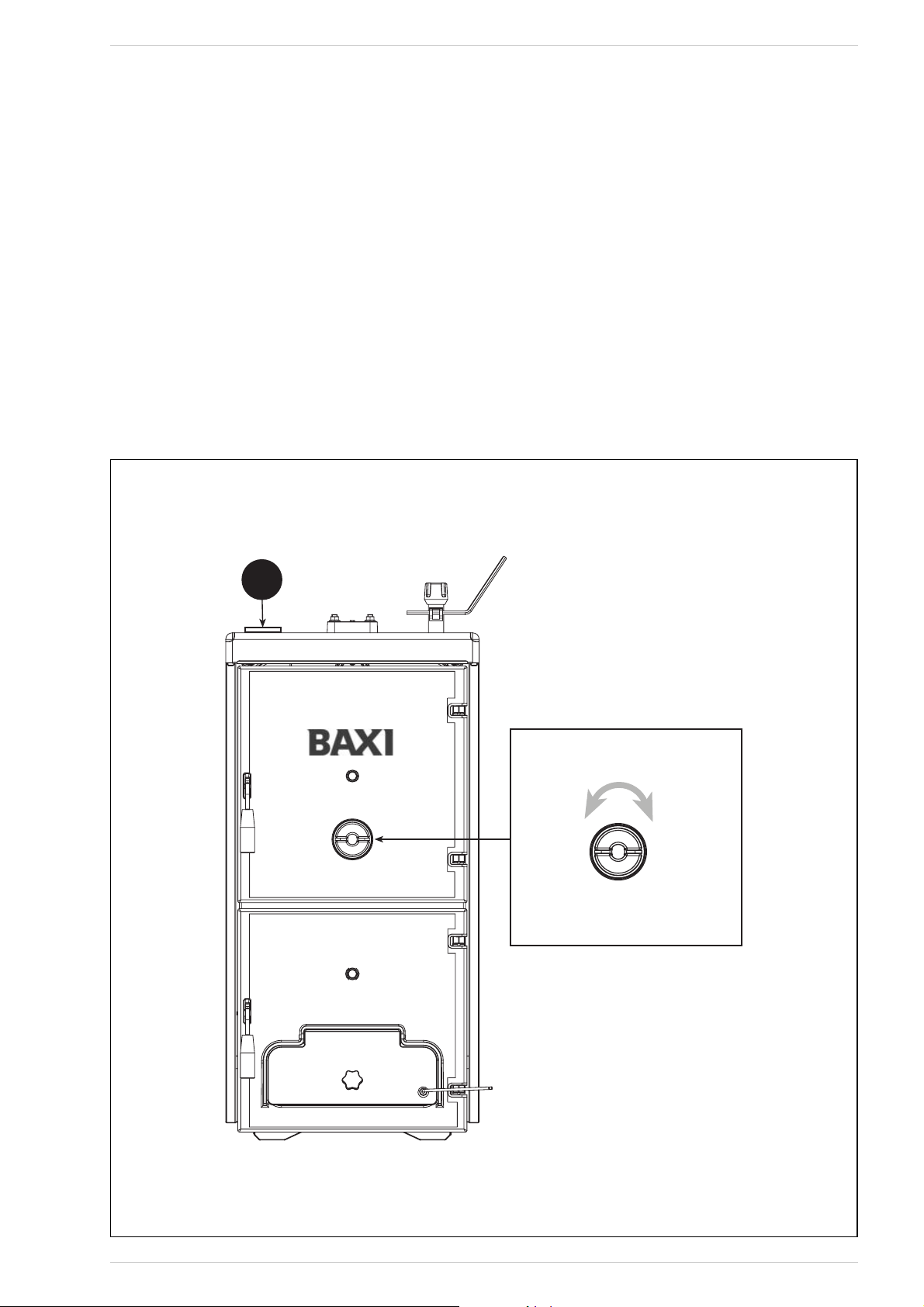
5.2 TERMOMETRO CALDAIA
(fig. 11)
Indica la temperatura dell’acqua di caldaia
(pos. 1).
5.3 REGOLAZIONE ARIA (fig. 11)
La regolazione dell’aria primaria avviene
automaticamente tramite la valvola termostatica, quella secondaria invece tramite la
portina rotonda posta sulla parte superiore della porta di caricamento, e deve essere regolata dall'utente.
Alla prima accensione è necessario regolare l'aria primaria e secondaria tenendo presente che l'aria primaria determina la
potenza della caldaia e quindi la quantità di
legna che viene bruciata e l'aria secondaria
completa la combustione.
La regolazione ottimale del funzionamento
della BPI-Eco si avrà con caldaia e camino
“in temperatura”.
In base alla legna utilizzata ed alla sua effettiva umidità, ruotare la portina rotonda (in
senso antiorario per aprire e in senso orario per chiudere) in modo da portare la
fiamma alle condizioni ottimali: colore aran-
5 USO E MANUTENZIONE
Fig. 11
1
APRE
CHIUDE
Page 11
cio-rosa-bianco con il centro tendente all'azzurro.
ATTENZIONE: Regolatore d’aria secondaria ad alte temperature! Usare guanti o
attrezzi idonei per non scottarsi.
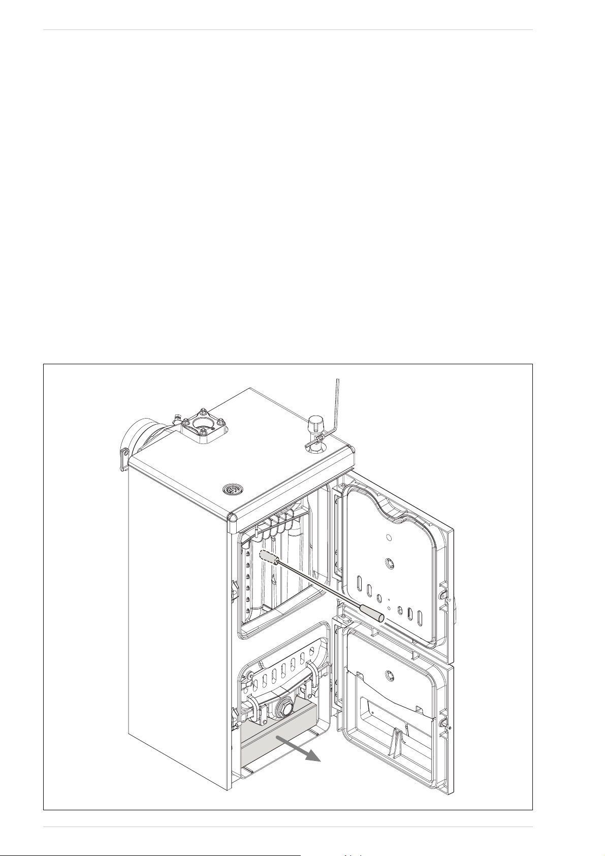
5.4 PULIZIA (fig. 12)
La pulizia deve essere effettuata con una
certa frequenza provvedendo, oltre alla pulizia dei passaggi fumo, anche alla pulizia del
cenerario togliendo le ceneri contenute
nella bacinella di raccolta.
Per la pulizia dei passaggi fumo utilizzare un
apposito scovolo.
5.5 MANUTENZIONE
Non effettuare alcuna operazione di manutenzione, smontaggio e rimozione senza prima
aver scaricato correttamente la caldaia. Le
operazioni di scarico non devono effettuarsi
con temperature dell’acqua elevate.
ATTENZIONE: La valvola di sicurezza dell’impianto deve essere verificata da personale tecnico qualificato in conformità
alle norme legislative del paese di distribuzione e al manuale d’uso della valvola di
sicurezza.
Nel caso l’impianto venga svuotato completamente e inutilizzato per lungo
tempo, è obbligatorio la verifica della valvola di sicurezza.
In caso di malfuzionamento della valvola
di sicurezza, ove non sia possibile la ritaratura, provvedere alla sostituzione con
una nuova valvola 1/2”, tarata 3 BAR e
conforme alla Direttiva PED 97/23/CEE.
5.6 SMALTIMENTO
DELL’APPARECCHIO
(DIRETTIVA EUROPEA
2002/96/CE)
L’apparecchio, giunto alla fine della sua vita
di utilizzazione, DEVE ESSERE SMALTITO IN
MODO DIFFERENZIATO, come previsto dalla
Legislazione Vigente.
NON DEVE essere smaltito assieme ai rifiuti urbani.
Può essere consegnato ai centri di raccolta differenziata, se esistenti, oppure ai
rivenditori che forniscono questo servizio.
Lo smaltimento differenziato evita potenziali danni all’ambiente e alla salute. Permette
inoltre di recuperare molti materiali riciclabili, con un importante risparmio economico ed energetico.
Fig. 12
11
Page 12

12
NOTES
Page 13

BPI-ECO - РУССКИЙ
СОДЕРЖАНИЕ
1 ПРЕДУПРЕЖДЕНИЯ ОБЩЕГО ХАРАКТЕРА . . . . . . . . . . . . . . . . . . . . . . . . . . . . . . . . . . . . . . . . . . . . 14
2 ПОСТАВКА . . . . . . . . . . . . . . . . . . . . . . . . . . . . . . . . . . . . . . . . . . . . . . . . . . . . . . . . . . . . . . . . . . . . . . . . 14
3 ТЕХНИЧЕСКИЕ ХАРАКТЕРИСТИКИ, РАЗМЕРЫ . . . . . . . . . . . . . . . . . . . . . . . . . . . . . . . . . . . . . . . . 15
3.1 ОПИСАНИЕ
3.2 ГАБАРИТНЫЕ РАЗМЕРЫ
3.3 ТЕХНИЧЕСКИЕ ДАННЫЕ
3.4 ПОТЕРИ НАГРУЗКИ
4 УСТАНОВКА ОБОРУДОВАНИЯ . . . . . . . . . . . . . . . . . . . . . . . . . . . . . . . . . . . . . . . . . . . . . . . . . . . . . . 16
4.1 КОТЕЛЬНАЯ
4.2 ПОДСОЕДИНЕНИЕ К ДЫМОХОДУ
4.3 ПОДКЛЮЧЕНИЕ УСТАНОВКИ
4.4 МОНТАЖ КОМПЛЕКТУЮЩИХ
4.5 МОНТАЖ КОЖУХА
4.6 РЕГУЛЯТОР ТЯГИ
4.7 ТЕПЛООБМЕННИК БЕЗОПАСНОСТИ
4.8 СХЕМЫ ГИДРАВЛИЧЕСКОГО ПОДКЛЮЧЕНИЯ
5 ЭКСПЛУАТАЦИЯ И ТЕХНИЧЕСКОЕ ОБСЛУЖИВАНИЕ . . . . . . . . . . . . . . . . . . . . . . . . . . . . . . . . . . . 20
5.1 ПРЕДВАРИТЕЛЬНЫЕ ПРОВЕРКИ ПЕРЕД ВКЛЮЧЕНИЕМ
5.2 ТЕРМОМЕТР КОТЛА
5.3 РЕГУЛЯТОР ВОЗДУХА
5.4 ОЧИСТКА
5.5 ТЕХНИЧЕСКОЕ ОБСЛУЖИВАНИЕ
Page 14

14
1 ПРЕДУПРЕЖДЕНИЯ ОБЩЕГО ХАРАКТЕРА
Руководство с инструкциями является
неотъемлемой частью изделия и
должно быть предоставлено
пользователю. Внимательно прочитать
предупреждения, содержащиеся в
руководстве, касающиеся установки,
эксплуатации и техобслуживания
оборудования. Бережно хранить
руководство для последующих
консультаций.
Установка оборудования должна
выполняться квалифицированным
персоналом в соответствии с
действующими нормативными
требованиями, следуя инструкциям
изготовителя. Неправильная установка
может привести к нанесению ущерба
людям или имуществу, за который
компания не несёт ответственности.
Проверить целостность изделия. В
сомнительных случаях не пользоваться
оборудованием, а обратиться к
поставщику. Элементы упаковки
должны подвергаться утилизации в
соответствии с действующими
нормативными требованиями.
Перед выполнением любых операций
техобслуживания оборудования,
отсоединить подачу электропитания на
него главным выключателем.
В случае поломки или неполадки,
выключить оборудование и не пытаться
самостоятельно ремонтировать его.
Обращаться в этих целях только к
квалифицированному технику.
Возможный ремонт должен
выполняться с использованием только
фирменных запчастей.
Несоблюдение вышеуказанного может
привести к поломке установки или её
отдельных компонентов, приведя к
возникновению потенциального риска
для безопасности пользователя, за что
компания не несёт никакой
ответственности.
Техобслуживание оборудования и
дымоходов должна производиться
по крайней мере раз в год.
2 ПОСТАВКА
Котёл, как показано на илл. 1,
поставляется упакованным в 2
отдельных упаковочных места:
– Чугунный корпус котла, в комплекте
с дымовой камерой с регулирующей
заслонкой, лотком для сбора золы и
термостатическим регулятором тяги.
В пакете содержится: 2 ручки для
двери, винт с ручкой из бакелита для
ручной регулировки заслонки впуска
воздуха, контактная пружина для
колбы термометра и рычаг M6 для
фиксирования заслонки впуска
воздуха. “Сертификат Проверочных
испытаний” и “Декларация
соответствия”, которые должны
храниться с документами на котёл.
– Картонная упаковка, содержащая
кожух, термометр и комплект
документации. Комплект
документации содержит: руководство
с инструкциями, гарантийный
сертификат, табличка с
ТЕХНИЧЕСКИМИ ДАННЫМИ КОТЛА
и блок этикеток для наклейки на
декларацию соответствия.
ВНИМАНИЕ: Табличка ТЕХНИЧЕСКИЕ
ДАННЫЕ КОТЛА, которая находится
в комплекте документации, является
адгезивной и должна наклеиваться
на боковину кожуха установщиком.
Паспортный номер чугунного
корпуса указан на табличке,
расположенной в верхней части
задней стороны корпуса.
Для облегчения транспортировки,
погрузки и разгрузки котла, на
верхней части его находятся
подъёмные крюки.
Илл. 1
1
2
Page 15

3 ТЕХНИЧЕСКИЕ ХАРАКТЕРИСТИКИ И РАЗМЕРЫ
3.1 ОПИСАНИЕ
Дерево - это очень ценный
альтернативный источник энергии,
поэтому необходимо использовать его
наилучшим образом, с применением
адекватных технологий сгорания.
Чугунные дровяные котлы с
традиционной технологией сжигания
BPI-Eco разработаны, чтобы
гарантировать максимальную отдачу с
оптимальной тягой.
Котлы отвечают требованиям
европейской Директивы PED 97/23/CEE
и стандарта EN 303-5.
3.2 ГАБАРИТНЫЕ РАЗМЕРЫ (Илл. 2)
Илл. 2
M
Диаметр поставляющей трубы
2” (UNI-ISO 7/1)
R
Диаметр возвратной трубы
2” (UNI-ISO 7/1)
S
Слив бойлера
1/2” (UNI-ISO 7/1)
123 4
0
5
10
15
20
Portata m3/h
∆p mbar
1.2 50
1.450
1.650
5
1.550
1.350
25
30
35
3.4
ГИДРАВЛИЧЕСКИЕ ПОТЕРИ
(Илл. 3)
15
Илл. 3
3.3 ТЕХНИЧЕСКИЕ ХАРАКТЕРИСТИКИ
BPI-Eco 1.250 1.350 1.450 1.550 1.650
Теплоотдача угля кВт 23,0 34,0 45,0 56,0 67,0
Максимальному дров кВт 20,0 30,0 40,0 49,0 58,0
Теплоотдача дров кВт 14,0 20,5 27,5 34,0 40,0
Класс кпд EN 303-5 11111
Одной загрузки угля хватает на час ≥ 4 ≥ 4 ≥ 4 ≥ 4 ≥ 4
Одной загрузки дров хватает на час ≥ 2 ≥ 2 ≥ 2 ≥ 2 ≥ 2
Объем загрузки дм
3
42,7 66,4 90,2 113,9 137,7
Допустимое понижение давления в дымовой трубе мБар 0,08 0,10 0,12 0,13 0,15
Размеры
P (глубина) мм 425 575 725 875 1025
L (глубина камеры сгорания) мм 346 496 646 796 946
Чугунные секции №3 4 5 6 7
Макс. рабочая температура °C 95 95 95 95 95
Минимальная температура воды на возврате в установку °C 50 50 50 50 50
Максимальное рабочее давление Бар 4 4 4 4 4
Давление при пробных испытаниях Бар 6 6 6 6 6
Объем теплоносителя л30 39 48 57 66
Вес кг 226 288 350 412 474
РАС ХО Д м3/час
347
392
500
211
ø 147
10 01
P
L
R
19 2
=
176
=
M
1023
825
S
15 5
Page 16

16
4.1 КОТЕЛЬНАЯ
Следует убедиться в том, что
помещение котельной отвечает
требованиям действующих норм. Кроме
того необходимо обеспечить
вентиляцию помещения,
предусмотренную для котельных.
Соответственно, в стенах помещения
следует создать вентиляционные
отверстия, отвечающие следующим
параметрам:
– На каждые 1,163 кВт (1000 ккал/час)
– не менее 6 см2вентиляционного
люка.
Минимальное вентиляционное
отверстие в любом случае не должно
быть менее 100 см2. Вентиляционный
отсек может быть рассчитан
следующим образом
где “S” выражено в см2, “Q” – в
ккал/час.
– Отверстие должно быть установлено
в нижней части стены,
противоположной стороне дымовой
трубы.
4.1.1 Размещение в помещении
котельной (
Илл.
4)
Котёл должен устанавливаться на
несгораемом фундаменте. После
выполнения установки, котёл должен
быть выровненным в горизонтальной
плоскости и устойчивым, в целях
уменьшения возможных вибраций и
создаваемого шума. Позади котла
необходимо оставить свободное
пространство, чтобы можно было
открыть и проводить техобслуживание
вентилятора.
ВНИМАНИЕ: Расстояния, указанные
на иллюстрации, являются
обязательными и касаются только
моделей с мощностью свыше 35 кВт.
4.2 ПОДВЕДЕНИЕ ДЫМОХОДА
Дымоход должен соответствовать
следующим требованиям:
– должен быть изготовлен из
материалов, которые способны
выдерживать температуру дыма и
соответствующие конденсаты;
– должен выдерживать механические
нагрузки и должен иметь слабую
теплопроводность;
– во избежании переохлаждения
дымовая труба должна быть
герметичной;
– должен быть как можно более
вертикальным и иметь вытяжное
устройство на конце трубы. Оно
должно гарантировать постоянный
эффективный выброс продуктов
сгорания;
– во избежании возможного эффекта
задымления при преобладании силы
ветра над силой выброса дыма
следует установить трубу как
минимум на 0,4 м выше любой
расположенной вблизи трубы
структуры (включая и сам конек
крыши) и на высоту не менее 8 м;
– диаметр дымохода не должен быть
меньше диаметра трубы соединения с
котлом: для дымоходов с квадратным
или прямоугольным сечением
внутреннее сечение должно быть на
10% больше сечения трубы
соединения с котлом;
– полезное сечение дымовой трубы
может быть вычислено с помощью
следующей формулы:
S сечение в см
2
K коэффициент уменьшения:
– 0,045 дерево
– 0,030 уголь
P мощность котла в ккал/час
H высота дымохода в метрах
(измерение должно проводиться
от линии пламени до верхней
внешней точки трубы). При
выборе размеров трубы
необходимо учитывать
фактическую высоту дымохода
(измеренную в метрах от пламени
до верхней внешней точки трубы)
уменьшенную на:
– 0,50 м при каждом изменении
направления трубы соединения
котла с дымовой трубой,
– 1,00 м на каждый метр
горизонтального положения
трубы соединения.
4.3 ПОДКЛЮЧЕНИЕ
ОБОРУДОВАНИЯ
При подключении рекомендуется
использовать жесткие штуцера, легко
рассоединяемые с помощью
вращающихся муфт. Обязательна
устанавка соответствующих
отключающих устройств на
трубопровод теплогенератора.
ВНИМАНИЕ! В системе в
обязательном порядке должен быть
установлен предохранительный
клапан не входит в комплект
поставки.
4.3.1 Заполнение установки
Перед тем, как приступать к
подключению котла следует
заставить циркулировать воду в
трубах, чтобы удалить возможные
посторонние тела, которые могут
негативно отразиться на
надлежащей работе оборудования.
Заполнение должно выполняться
медленно, чтобы позволить выйти
пузырькам воздуха через
соответствующие воздуховыпускные
клапаны, имеющиеся в отопительной
системе. В отопительных системах с
закрытым контуром давление нагрузки
в холодной системе и давление
предварительного накачивания
расширительного бака должны
соответствовать или, по крайней мере,
быть не ниже показаний шкалы
статической колонны системы
(например, для статической колонны в
5 метров, давление преднагрузки в
баке и давление нагрузки в системе
должны быть равны, как минимум, 0,5
бар).
4.3.2 Требования к воде
Вода-теплоноситель должна
соответствовать норме UNI-CTI 8065.
Следует напомнить, что
накипеобразования в несколько
миллиметров толщиной вызывают в
следствие их низкой теплопроводности
значительное перегревание панелей
котла, приводящее к нежелательным
последствиями. ОБЯЗАТЕЛЬНОЙ
ЯВЛЯЕТСЯ ОБРАБОТКА ВОДЫ В
СЛЕДУЮЩИХ СЛУЧАЯХ:
– Крупные системы (с большим
объёмом воды).
– Высокая цикличность подачи
4 УСТАНОВКА ОБОРУДОВАНИЯ
Q
S=
100
P
S=K
√H
Илл. 4
600
1000
BAXI
600
1000
600
1300
Page 17

использованной воды.
– После частичного или полного
опорожнивания оборудования.
4.4 МОНТАЖ КОМПЛЕКТУЮЩИХ
(
Илл.
5 -
Илл.
5/a)
Ручки закрытия дверок и винт с
рукояткой для регулировки заслонки
впуска воздуха поставляются в
отдельной упаковки, во избежание их
повреждения при транспортировке. Как
ручки, так и винт с рукояткой находятся
в нейлоновых пакетах внутри зольника
для сбора золы.
Для установки ручек действовать
следующим образом (илл. 5):
– Взять ручку (1), вставить её в
отверстие загрузочной дверки (2),
затем вставить ролик (3) в отверстие
в ручке; заблокировать ручку,
вставив эластичный штифт (4).
– Выполнить эту же операцию для
установки ручки зольника.
Для установки винта с рукояткой
действовать следующим образом (илл.
5/a):
– Удалите винт M8 x 60, которым
прикреплена заслонка впуска
воздуха к дверце зольника, и
привинтите винт с рукояткой из
бакелита (1) из комплекта поставки.
Установите на конец винта M10
глухую колпачковую гайку (2).
– Прикрепить рычаг M6 (3) к
воздушной заслонке, установив её в
горизонтальном положении вправо.
На конце рычага имеется отверстие,
куда затем подсоединяется цепочка
термостатического регулятора.
4.5 МОНТАЖ КОЖУХА (
Илл.
6)
С задней стороны котла, на двух
верхних тягах, привинчены 3 гайки:
Вторая и третья гайка служат для
Илл. 6
17
ОБОЗНАЧЕНИЯ
1 Рукоятка
2 Загрузочная дверка
3 Ролик
4 Эластичный штифт
Илл. 5
ОБОЗНАЧЕНИЯ
1 Винт с рукояткой M10 x 70
2Глухая колпачковая гайка
3 Рычаг M6
Илл. 5/a
1
2
3
8
7
4
6
1
5
2
Page 18

18
правильной установки боковин кожуха.
На нижних тягах, как спереди, так и
сзади, котла, привинчены 2 гайки, одна
из которых служит для блокировки
опорных скоб боковин. Установка
компонентов кожуха должна
выполняться следующим образом:
– Отвинтите на несколько оборотов
вторую и третью гайку на каждой
тяге.
– Прикрепить левую боковину (1) к
нижней и верхней тяге котла и
отрегулировать положение гайки и
контргайки верхней тяги.
– Заблокировать боковину, затянув
контргайки.
– Для установки правой боковины (2)
действовать аналогично.
– Прикрепите заднюю панель (4) введя
язычки в щелевые отверстия на
каждой боковине, и прикрепите её к
боковинам шестью самонарезными
болтами.
– Защитный дефлектор (5) прикреплён
к передней панели (6) тремя
самонарезными болтами. Разместить
между двумя элементами
минеральную вату.
– Закрепите переднюю панель (6),
надавив на нажимные штырьки.
– Отвинтить капиллярную трубку
термометра (7) и вставить её в кожух
с заднего торца, вставив контактную
пружину, которую необходимо
обрезать примерно до 45 мм. Провод
термометра должен укладываться
поверх изоляционного материала, а
не в прямом соприкосновении с
чугунным корпусом.
– Прикрепите крышку (8) к боковинам
котла, надавив на нажимные
штырьки.
- Приклеить табличку ТЕХНИЧЕСКИЕ
ДАННЫЕ КОТЛА на правую или
левую боковину кожуха, чтобы она
была хорошо видна на
установленном оборудовании.
ПРИМЕЧАНИЕ: Бережно хранить
документы на котёл “Сертификат
Проверочных испытаний” и
“Декларацию о соответствии”,
которые найдёте в камере сгорания.
4.6 РЕГУЛЯТОР ТЯГИ
ТЕРМОСТАТИЧЕСКОГО
ДЕЙСТВИЯ
При помощи термостатического
регулятора тяги можно постоянно
получать различный поток воздуха,
поступающего в топку котла.
Этот регулятор, при помощи
соединительной цепочки, воздействует
на нижнюю дверцу впуска первичного
воздуха. При достижении заданной
температуры, регулятор немедленно
уменьшает открытое отверстие дверцы
впуска воздуха, замедляя таким
образом горение и предотвращая
излишний перегрев. В целях
оптимизации процесса горения, на
верхней загрузочной дверке находится
круглая дверца для регулировки,
которая позволяет распределять
вторичный воздух, который движется в
противоположном направлении
относительно потока продуктов
сгорания. Этот процесс, который
дополнительно повышает КПД
оборудования, позволяет более
эффективно использовать топливо.
На котле могут быть установлены,
безразлично по вашему выбору, два
типа термостатических регуляторов.
4.6.1 Терморегулятор
"THERMOMAT RT-C" (
Илл.
7)
Регулятор "Thermomat" укомплектован
рукояткой из термореактивной смолы, с
возможностью установки температуры
от 30 до 100 °С. Следует ввинтить
регулятор в отверстие 3/4” торцевой
части, красный показатель должен
быть направлен вверх.
После того, как панель инструментов
установлена и снято пластиковое
блокировочное устройство, рычаг с
цепочкой должен быть введен в опору
регулятора.
В случае, если распустится шарнирное
соединение, крепящее рычаг с
цепочкой, следует восстановить его.
Когда ручка установлена на 60°С,
закрепляется рычаг с цепочкой.
Следует выбрать позицию под углом
вниз, таким образом цепочка окажется
на одной оси с крепежным отверстием
шибера подачи воздуха. Регулировка
"Thermomat" заключается в изменении
длины цепочки. Действуйте следующим
образом:
– Установите ручку на 60°С.
– Оставив шибер подачи воздуха
открытым, включите котел.
– Когда вода достигнет 60°С,
установите цепочку на рычаг шибера,
образуя щель размером в 1 мм.
– Теперь регулятор откалиброван,
рабочую температуру можно менять,
поворачивая ручку.
4.6.2 Регулятор "REGULUS RT2"
(
Илл.
8)
Диапазон регулирования – от 30 до
90°С. Для установки и запуска
регулятора следуйте инструкциям
регулятора "Thermomat".
4.7 ТЕПЛООБМЕННИК
БЕЗОПАСНОСТИ
LТеплообменник безопасности
поставляется по заявке в наборе:
-
код
8105200 для BPI-Eco
1.250/1.350/1.450
-
код
8105201 для BPI-Eco 1.550/1.650.
Набор можно использовать для
установки только на отопительных
системах с закрытым расширительным
баком, с мощностью менее 35 кВт.
Он предназначен для охлаждения
котла при его перегреве при помощи
клапана сброса избыточной
температуры, гидравлически
подключённым на входе в
теплообменник.
Предусмотреть установку на выходе из
теплообменника дренажной трубы с
воронкойили сифона, которые
направляют к соответствующему сливу.
Слив должен быть хорошо виден для
его контролирования.
ВНИМАНИЕ: При отсутствии этих
предосторожностей возможное
срабатывание клапана сброса
избыточного тепла может привести к
нанесению ущерба людям,
животным и имуществу, за которые
изготовитель не несёт никакой
ответственности. Перед вводом в
эксплуатацию котла убедитесь в
наличии подачи потока воды к
клапану сброса избыточного тепла.
Илл. 8
Терморегулятор “REGULUS RT2”
Илл. 7
Терморегулятор “THERMOMAT RT-C”
Page 19

4.8 СХЕМА ГИДРАВЛИЧЕСКИХ СОЕДИНЕНИЙ
4.8.1 Система с расширительным бачком открытого типа (Илл. 9)
Илл. 9
4.8.2 Система с расширительным бачком закрытого типа и термостатическим
клапаном, поставляемым по отдельному заказу (Илл. 10)
Илл. 10
ОБОЗНАЧЕНИЯ
VE Расширительный бачок
VS Предохранительный клапан 3 BAR - 1/2”
VM Распределительный клапан
VR Запорный клапан
PI Циркуляционный насос
IR Отопительная система
VT Термостатический клапан
SC Предохранительный теплообменник
F Фильтр
ВНИМАНИЕ! Предохранительный
теплообменник поставляется в дополнительном
комплекте, код 8105200/01.
Температура воды на подаче в
предохранительный теплообменник: 10°C.
Давление воды на подаче в предохранительный
теплообменник: 2 бар.
Установка защитного теплообменника (SC)
обязательна.
Перед вводом в эксплуатацию котла убедитесь
в наличии подачи потока воды к
термостатическому клапану (VT).
19
ОБОЗНАЧЕНИЯ
VE Расширительный бачок открытого типа
VS Предохранительный клапан 3 BAR - 1/2”
VM Распределительный клапан
VR Запорный клапан
PI Циркуляционный насос
IR Отопительная система
BPI-Eco
BPI-Eco
Page 20

20
5.1 ПРЕДВАРИТЕЛЬНЫЕ
ПРОВЕРКИ ПЕРЕД
ВКЛЮЧЕНИЕМ
Перед вводом в эксплуатацию котла
необходимо следовать
нижеприведённым инструкциям:
– Отопительная система, к которой
подключается котёл, должна быть, по
возможности, системой с
расширительным баком открытого
типа (илл. 9).
– Труба , соединяющая котёл с
расширительным баком, должна
иметь диаметр в соответствии с
действующими нормативными
требованиями.
– Тепловой насос должен всегда
работать во время функционирования
котла.
– Работа насоса никогда не должна
прерываться срабатыванием
комнатного термостата.
– Если отопительная система оснащена
3-х или 4-ходовым смесительным
клапаном, то он всегда должен
находиться в открытом положении в
сторону отопительной системы.
– Проверить, что регулятор тяги
работает правильно и ничто не
мешает, блокируя, работе в
автоматическом режиме заслонки
подачи воздуха.
5.2 TЕРМОМЕТР КОТЛА
(илл. 11)
Показывает температуру воды в котле
(поз. 1).
5.3 РЕГУЛЯТОР ВОЗДУХА
(илл. 11)
Регулировка первичного воздуха
происходит автоматически при помощи
термостатического клапана; вторичный
воздух, наоборот, регулируется круглой
дверцей, расположенной в верхней
части загрузочной дверки, и должен
регулироваться вручную пользователем.
При первом включении необходимо
отрегулировать первичный и вторичный
воздух, учитывая , что первичный
воздух определяет мощность котла, а
значит и на количество сжигаемых дров,
а вторичный воздух завершает горение.
Оптимальная регулировка
функционирования BPI-Eco
производится при “хорошо разогретом”
котле или камине.
В зависимости от типа используемой
древесины, а также её влажности,
отрегулировать, повернув, круглую
дверцу (против часовой стрелки - чтобы
открыть, по часовой стрелке - чтобы
закрыть) так, чтобы пламя было в
оптимальном состоянии: цвет пламени
должен быть оранжевым- светлорозовым, а в центре -голубоватым.
ВНИМАНИЕ: Регулятор вторичного
воздуха с высокими температурами!
Пользоваться термозащитными
перчатками или подходящими
устройствами, во избежание ожога.
5.4 ЧИСТКА (илл. 12)
LЧистка должна выполняться регулярно
и с определённой периодичностью,
очищая не только дымоход, но и
зольник, удалив золу из сборочного
лотка. Для очистки дымовых каналов
пользоваться специальным ёршиком.
5.5 ТЕХНИЧЕСКОЕ
ОБСЛУЖИВАНИЕ
Не выполнять никаких операций по
обслуживанию, демонтажу и
перемещению, не слив перед этим
должным образом воду из котла.
Операции слива не должны
осуществляться при повышенной
температуре воды.
ВНИМАНИЕ! Предохранительный
клапан должен проверяться
квалифицированным специалистом в
соответствии с законами страны,
распределения и инструкции по
использованию предохранительного
клапана. В случае если вода будет
полностью слита из системы, которая
не будет использоваться
продолжительное время, в
обязательном порядке следует
выполнить проверку
предохранительного клапана.
В случае выхода из строя
предохранительного клапана и при
невозможности его ремонта,
необходимо заменить его новым
предохранительным клапаном 1/2”,3
бара, соответствующим требованиям
Директивы PED 97/23/CEE.
5 ЭКСПЛУАТАЦИЯ И ТЕХНИЧЕСКОЕ ОБСЛУЖИВАНИЕ
Илл. 11
Илл. 12
Открывает
Закрывает
1
APRE
CHIUDE
Page 21

BPI-ECO - FRANÇAIS
TABLES DES MATIÈRES
1 MISES EN GARDE GÉNÉRALES . . . . . . . . . . . . . . . . . . . . . . . . . . . . . . . . . . . . . . . . . . . . . . . . . . . . . . . . . . . . . . . . . . . . . . . 22
2 FOURNITURE . . . . . . . . . . . . . . . . . . . . . . . . . . . . . . . . . . . . . . . . . . . . . . . . . . . . . . . . . . . . . . . . . . . . . . . . . . . . . . . . . . . . . . . . 22
3 CARACTÉRISTIQUES TECHNIQUES ET DIMENSIONS . . . . . . . . . . . . . . . . . . . . . . . . . . . . . . . . . . . . . . . . . . . . . . . . . . . 23
3.1 DESCRIPTION
3.2 DIMENSIONS D'ENCOMBREMENT
3.3 CARACTÉRISTIQUES TECHNIQUES
3.4 PERTES DE CHARGE
4 INSTALLATION . . . . . . . . . . . . . . . . . . . . . . . . . . . . . . . . . . . . . . . . . . . . . . . . . . . . . . . . . . . . . . . . . . . . . . . . . . . . . . . . . . . . . . . 24
4.1 LOCAL DE LA CHAUDIÈRE
4.2 BRANCHEMENT AU CONDUIT DE FUMÉE
4.3 RACCORDEMENT DE L'INSTALLATION
4.4 MONTAGE DES ACCESSOIRES
4.5 MONTAGE DU REVÊTEMENT
4.6 RÉGULATEUR DE TIRAGE
4.7 ÉCHANGEUR DE CHALEUR DE SÉCURITÉ
4.8 SCHÉMAS DE RACCORDEMENT HYDRAULIQUE
5 UTILISATION ET MAINTENANCE . . . . . . . . . . . . . . . . . . . . . . . . . . . . . . . . . . . . . . . . . . . . . . . . . . . . . . . . . . . . . . . . . . . . . . 28
5.1 CONTRÔLES PRÉLIMINAIRES À L'ALLUMAGE
5.2 THERMOMÈTRE CHAUDIÈRE
5.3 RÉGULATION AIR
5.4 NETTOYAGE
5.5 MAINTENANCE
Page 22

22
1 MISES EN GARDE GÉNÉRALES
Le manuel d'instruction fait partie intégrante du produit et doit être remis à l'utilisateur. Lire attentivement les mises en garde
qui y sont contenues concernant l'installation, l'utilisation et la maintenance de l'appareil. Conserver soigneusement le manuel
pour toute ultérieure consultation.
L'installation doit être effectuée par du personnel qualifié, conformément aux normes
en vigueur suivant les instructions du fabricant. Une installation erronée peut causer
des dommages aux personnes ou aux biens
dont l'entreprise décline toute responsabilité.
S'assurer de l'intégrité du produit. En cas
de doute, ne pas utiliser l'appareil et contacter le fournisseur.
Les éléments d'emballage doivent être éliminés conformément à la norme en
vigueur.
Avant d'effectuer toute opération de maintenance sur l'appareil, débrancher l'alimentation électrique en agissant sur l'interrupteur de l'installation.
En cas de panne ou de dysfonctionnement,
désactiver l'appareil et éviter toute tentative de réparation ou d'intervention directe.
Contacter exclusivement un technicien qualifié. L'éventuelle réparation ne doit se faire
qu'en utilisant des pièces de rechange originales.
Le non-respect des indications susmentionnées peut compromettre l'intégrité de
l'installation ou d'un composant quelconque,
causant ainsi un danger possible pour la
sécurité de l'utilisateur; le fabricant en
décline toute responsabilité.
Vous devez effectuer la maintenance de
l'appareil et du conduit des fumées au
moins une fois l'an.
2 FOURNITURE
La chaudière (comme l'indique la figure 1) est
fournie en de colis séparés:
– Le corps de la chaudière en fonte équipé
d'une chambre à fumée dotée de clapet
de réglage, une cuvette de collecte des
cendres et un régulateur thermostatique de tirage.
Un sachet contenant: 2 poignées pour
les portes, une vis avec pommeau en
bakélite pour le réglage manuel du clapet
d'introduction d'air, un ressort de contact pour la boule de thermomètre et le
levier M6 à fixer au clapet d'introduction
d'air. “Certificat d'Essai” et “Déclaration
de conformité” à conserver avec les
documents de la chaudière.
– Emballage carton avec revêtement, ther-
momètre et kit des documents. Le kit
des documents comprend: le manuel
d'instructions, le certificat de garantie, la
plaquette des CARACTÉRISTIQUES
TECHNIQUES et l'imprimé des étiquettes
à appliquer sur la déclaration de conformité.
ATTENTION: La plaquette des CARACTÉ-
RISTIQUES TECHNIQUES contenue dans
le kit des documents est adhésive et doit
être appliquée sur un flanc du revêtement par les soins de l'installateur.
Le numéro de série du corps en fonte est
indiqué sur la plaquette rivetée sur la partie supérieure arrière du corps.
Pour faciliter le transport, le chargement
et le déchargement de la chaudière, sur
sa partie supérieure, nous avons prévu
des crochets spécifiques pour le levage.
Fig. 1
1
2
Page 23

3 CARACTÉRISTIQUES TECHNIQUES ET DIMENSIONS
3.1 DESCRIPTION
Le bois est une source d'énergie alternative
et précieuse; il est donc fondamental de l'utili-
ser de la meilleure façon possible en adoptant des technologies appropriées pour la
combustion. Les chaudières à bois en fonte à
combustion traditionnelle BPI-Eco sont
conçues pour assurer le rendement thermique maximum en optimisant le tirage. Les
chaudières sont conformes à la Directive PED
(DESP) 97/23/CEE et à la Norme EN 303-
5.
3.2 DIMENSIONS D'ENCOMBREMENT (fig. 2)
Fig. 2
M Refoulement installation 2” (UNI-ISO 7/1)
R Retour installation 2” (UNI-ISO 7/1)
S Déchargement chaudière 1/2” (UNI-ISO 7/1)
Fig. 3
123 4
0
5
10
15
20
Portata m3/h
∆p mbar
1.2 50
1.450
1.650
5
1.550
1.350
25
30
35
3.4 PERTES DE CHARGE (fig. 3)
23
3.3 CARACTÉRISTIQUES TECHNIQUES
BPI-Eco 1.250 1.350 1.450 1.550 1.650
Puissance thermique au charbon kW
23,0 34,0 45,0 56,0 67,0
Puissance max. au bois kW 20,0 30,0 40,0 49,0 58,0
Puissance thermique au bois kW 14,0 20,5 27,5 34,0 40,0
Classe de rendement EN 303-5 111 11
Durée d'une charge au charbon h ≥ 4 ≥ 4 ≥ 4 ≥ 4 ≥ 4
Durée d'une charge au bois h ≥ 2 ≥ 2 ≥ 2 ≥ 2 ≥ 2
Volume de charge dm
3
42,7 66,4 90,2 113,9 137,7
Dépression minimum à la cheminée mbar 0,08 0,10 0,12 0,13 0,15
Dimensions
P (profondeur) mm 425 575 725 875 1025
L (profondeur chambre combustion) mm 346 496 646 796 946
Éléments de fonte n° 3 4 5 6 7
Température max. fonctionnement °C 95 95 95 95 95
Température min. eau retour installation °C 50 50 50 50 50
Pression max. fonctionnement bar 4 4 4 4 4
Pression d'essai bar 6 6 6 6 6
Capacité chaudière l303948 5766
Poids kg 226 288 350 412 474
DEBIT m3/h
347
392
500
211
ø 147
10 01
P
L
19 2
M
1023
825
R
=
=
176
S
15 5
Page 24

24
4.1 LOCAL CHAUDIÈRE
Vérifier que le local présente bien les qualités
et les caractéristiques correspondantes aux
normes légales en vigueur.
Il est en outre nécessaire qu'afflue dans la
pièce une quantité d'air correspondant pour
le moins à la quantité nécessaire pour assurer une combustion régulière.
Il est donc nécessaire de pratiquer, dans les
murs du local, des ouvertures qui répondent
aux prescriptions suivantes:
- Présenter une section libre d'au moins 6
cm2tous les 1,163 kW (1000 kcal/h).
La section minimum de l'ouverture ne doit
de toute façon pas être inférieure à 100
cm2. La section peut en outre être calculée en utilisant le rapport suivant:
où "S" est exprimé en cm2, “Q” in kcal/h
– L'ouverture doit être située dans la par-
tie inférieure d'un mur extérieur, préférablement opposée à celle dans laquelle se
trouve l'évacuation des gaz brûlés.
4.1.1 Emplacement en centrale
thermique (fig. 4)
La chaudière doit être installée sur un bâti
non combustible. Après l'installation, la
chaudière doit être horizontale et bien stable pour réduire les éventuelles vibrations
et le niveau sonore. Derrière la chaudière,
vous devez laisser un espace libre pour permettre l'ouverture et la maintenance du
ventilateur.
ATTENTION: Les distances minimales indiquées sur la figure sont contraignantes
et uniquement pour les modèles ayant
une puissance supérieure à 35 kW.
4.2 BRANCHEMENT AU CONDUIT
DE CHEMINÉE
UUn conduit de cheminée doit répondre
aux prescriptions de qualité suivantes :
- Il doit être constitué d'un matériau
imperméable et résistant à la température des fumées et aux condensations
correspondantes.
- Il doit présenter une résistance mécanique suffisante et une faible conductivité
thermique.
- Il doit être parfaitement étanche pour
éviter le refroidissement du conduit de
cheminée lui-même.
- Il doit avoir un tracé le plus vertical possible et la partie terminale doit être
équipée d'un aspirateur statique qui
assure une évacuation efficace et constante des produits de la combustion.
- Dans le but d'éviter que le vent puisse
créer autour de la cheminée des zones
de pression qui seraient en mesure de
prévaloir sur la force ascensionnelle des
gaz brûlés, il est nécessaire que l'orifice
de déchargement domine d'au moins
0,4 mètres toute structure proche de la
cheminée elle-même (y compris le faîte
du toit) et qui se trouve à une distance
de moins de 8 mètres.
- La conduit de cheminée doit présenter
un diamètre qui n'est pas inférieur à
celui du raccord de chaudière ; dans le
cas de conduits de cheminée présentant
une section carrée ou rectangulaire, la
section intérieure doit être augmentée
de 10 % par rapport à celle du raccord
de chaudière.
- La section utile du conduit de cheminée
peut être extrapolée sur la base du rapport ci-dessous.
S section résultant en cm
2
K coefficient en réduction:
– 0,045 pour bois
– 0,030 pour charbon
P puissance de la chaudière en
kcal/h
H hauteur de la cheminée en mètres
mesurés à partir de l'axe de la flamme jusqu'à l'évacuation de la cheminée dans l'atmosphère.
Pour procéder au dimensionnement
du conduit de cheminée, on doit
tenir compte de la hauteur effective
de la cheminée en mètres, mesurée
de l'axe de la flamme jusqu'au sommet, diminuée de:
– 0,50 m pour chaque changement
de direction du tuyau de raccor-
dement entre chaudière et conduit de cheminée;
– 1,00 m pour chaque mètre de
développement horizontal du raccordement lui-même.
4.3 BRANCHEMENT INSTALLATION
Il est souhaitable que les connexions puissent être aisément détachées, à l'aide de
tubulures avec raccords tournants.
Il est toujours conseillé de monter des vannes d'arrêt sur les canalisations de l'installation de chauffage.
ATTENTION : Il est obligatoire de procéder au montage de la soupape de sécurité sur l'installation pas inclus dans la
livraison.
4.3.1 Remplissage installation
Avant de procéder au raccordement de la
chaudière, il convient de faire circuler de
l'eau dans les canalisations afin d'éliminer
les éventuels corps étrangers en mesure
de compromettre le bon fonctionnement
de l'appareil.
Le remplissage doit être effectué lentement, afin de permettre aux bulles d'air de
sortir à travers les orifices de purge prévis
à cet effet et placés sur l'installation de
chauffage. Dans les installations de chauffage à circuit fermé, la pression de chargement à froid de l'installation et la pression
de prégonflage du vase d'expansion
devront correspondre ou, dans tous les
cas, ne pas être inférieurs à la hauteur de
la colonne statique de l'installation (par
exemple, pour une colonne statique de 5
mètres, la pression de préchargement du
vase et la pression de chargement de l'installation devront correspondre à une
valeur minimum de 0,5 bars au moins.
4.3.2 Caractéristiques de
l'eau d'alimentation
L'eau d'alimentation du circuit de chauffage
doit être traitée conformément à la Norme
UNI-CTI 8065. Il convient de rappeler que
même de petites incrustations de quelques
4 INSTALLATION
Q
S=
10 0
P
S=K
√H
Fig. 4
600
BAXI
1000
1000
600
600
1300
Page 25

millimètres d'épaisseur provoquent, en raison de leur basse conductivité thermique,
une surchauffe considérable des parois de
la chaudière ce qui provoque de graves
inconvénients. LE TRAITEMENT DE L'EAU
UTILISÉE POUR L'INSTALLATION DE CHAUFFAGE EST ABSOLUMENT INDISPENSABLE
DANS LES CAS SUIVANTS:
- Installations très étendues, avec contenus en eau élevés.
- Introductions fréquentes d'eau de remise à niveau dans l'installation.
- Au cas où une vidange partielle ou totale
de l'installation s'avérerait indispensable.
4.4 MONTAGE DES ACCESSOIRES
(fig. 5 - fig. 5/a)
Les poignées de fermeture des portes et la
vis avec pommeau pour le réglage du clapet d'introduction d'air sont fournies
séparément, car ils pourraient s'endommager durant le transport. Les poignées et la
vis avec pommeau sont contenues dans
des sachets en nylon introduits dans la
cuvette de collecte des cendres. Pour le
montage des poignées, procéder comme
suit (fig. 5) :
– Prendre une poignée (1), l'introduire
dans la fente de la porte de chargement
(2) et insérer le rouleau (3) dans le trou
de la poignée; bloquer la poignée en insérant la goupille élastique (4).
– Effectuer la même opération pour la poi-
gnée de la porte du cendrier.
Pour le montage de la vis avec pommeau,
procéder comme suit (fig. 5):
– Enlever la vis M8 x 60 qui fixe le clapet
d'introduction d'air à la porte du cendrier
et visser la vis avec pommeau en bakélite (1) fournie dans l'emballage. À l'extrémité de la vis M10, placer un écrou borgne avec calotte (2).
– Fixer le levier M6 (3) au clapet d'air en le
plaçant horizontalement vers la droite. À
l'extrémité du levier se trouve un trou
sur lequel sera ensuite reliée la chaînette du régulateur thermostatique.
4.5 MONTAGE DU REVÊTEMENT (fig. 6)
Du côté arrière de la chaudière, sur les
Fig. 6
25
LÉGENDE
1 Poignée
2 Porte de chargement
3 Rouleau
4 Goupille élastique
Fig. 5
LÉGENDE
1 Vis avec pommeau M10 x 70
2 Écrou borgne avec calotte
3 Levier M6
Fig. 5/a
8
1
2
3
7
4
6
1
5
2
Page 26

26
deux tirants supérieures, sont vissés trois
écrous: le deuxième et le troisième écrou
servent à placer correctement les flancs
du revêtement. Dans les tirants inférieurs,
aussi bien de la partie avant que de la partie arrière de la chaudière, deux écrous
sont vissés dont l'un pour bloquer les
étriers de support des flancs. Le montage
des composants du revêtement doit être
effectué de la manière suivante:
– Dévisser de quelques tours le deuxième
et le troisième écrou de chaque tirant.
– Accrocher le flanc gauche (1) sur le
tirant inférieur et supérieur de la chaudière, puis régler la position de l'écrou et
du contre-écrou du tirant supérieur.
– Bloquer le flanc en serrant les contre-
écrous.
– Pour monter le flanc droit (2), procéder
de la même manière.
– Accrocher le panneau arrière (4) en
insérant les languettes dans les fentes
obtenues sur chaque flanc, puis le bloquer sur les flancs à l'aide de six vis autotaraudeuses.
– Le déflecteur de protection (5) est fixé
au panneau frontal (6) à l'aide de trois
vis auto-taraudeuses. Entre les deux éléments, insérer la laine de roche.
– Fixer le panneau frontal (6) à l'aide des
piquets à pression.
– Dérouler le capillaire du thermomètre
(7) et l'introduire dans la gaine de la tête
arrière en insérant la pince de contact
qui doit être coupée à environ 45 mm.
Le câble du thermomètre doit être placé
au-dessus de l'isolant et non pas en contact direct avec le corps en fonte.
– Fixer le couvercle (8) aux flancs de la
chaudière à l'aide des piquets à pression.
– Accrocher la plaquette adhésive des
CARACTÉRISTIQUES TECHNIQUES au
flanc droit ou gauche du revêtement de
manière qu'elle soit lisible à la fin de l'installation.
REMARQUE: Conserver avec les documents de la chaudière le “Certificat d'Essai” et la “Déclaration de conformité”
placés dans la chambre de combustion.
4.6 RÉGULATEUR DE TIRAGE
À FONCTIONNEMENT
THERMOSTATIQUE
Le régulateur de tirage à fonctionnement
thermostatique permet d'obtenir une variabilité continue d'air introduit dans le foyer
de la chaudière. Ce régulateur, à travers
une chaînette de raccordement, agit sur la
porte inférieure d'introduction d'air primaire. Lorsque la température établie est
atteinte, le régulateur diminue automatiquement l'ouverture de la porte d'introduction d'air de manière à ralentir la combustion et éviter les surchauffes.
Dans le but d'optimiser la combustion, sur
la porte supérieure de chargement, se
trouve une porte ronde de régulation qui
distribue de l'air secondaire à contre-cou-
rant rapport au trajet des produits de la
combustion. Ce processus augmentant
ultérieurement le rendement, permet d'exploiter de manière plus efficace le combustible. Sur les chaudières, l'on peut monter
indifféremment deux types de régulateurs
thermostatiques.
4.6.1 Régulateur “THERMOMAT RT-C”
(fig. 7)
Le régulateur "Thermomat" est équipé d'un
bouton en résine thermodurcissable avec
champ de régulation de 30 à 100 °C.
Visser le régulateur sur le trou 3/4" de la
tête antérieure et orienter la marque rouge
vers la partie supérieure. Le levier avec chaînette doit être introduit dans le support du
régulateur après avoir monté le panneau
porte-instruments et après avoir enlevé
l'arrêt en plastique. Si l'articulation qui fixe le
levier avec chaînette devait se défaire, il faut
veiller à le remonter dans la même position.
Après avoir placé le bouton sur 60°C, bloquer le levier avec chaînette dans une position légèrement inclinée vers le bas, de
manière que la chaîne se trouve dans l'axe
par rapport au raccord du volet de l'air.
Pour la régulation du "Thermomat", qui consiste essentiellement à déterminer la longueur de la chaînette, procéder de la manière suivante :
- Placer le bouton sur 60 °C.
- Allumer la chaudière avec le rideau d'in-
troduction de l'air ouvert.
- Au moment où une température de 60
°C de l'eau de la chaudière est atteinte,
fixer la chaînette sur le levier du clapet
d'introduction de l'air en faisant en sorte
que ce dernier présente une ouverture
d'environ 1 mm.
- À ce stade, le régulateur est réglé et il
est possible de choisir la température de
travail souhaitée en tournant le bouton.
4.6.2 Régulateur “REGULUS RT2”
(fig. 8)
Le champ de régulation est compris entre
30 et 90°C (fig. 8). Pour le montage et la
mise en fonction, suivre les mêmes instructions que pour le régulateur "Thermomat".
4.7 ÉCHANGEUR DE CHALEUR
DE SÉCURITÉ
L'échangeur de chaleur de sécurité est
fourni sur demande dans un kit :
- code 8105200 pour BPI-Eco
1.250/1.350/1.450
- code 8105201 pour BPI-Eco
1.550/1.650.
Le kit doit être utilisé sur les installations à
vase d'expansion fermé et de puissance
inférieure à 35 kW. Sa fonction est de
refroidir la chaudière en cas de surchauffe,
au moyen d'une vanne de décharge thermique raccordée de manière hydraulique à
l'entrée de l'échangeur.
Prévoir au niveau de la sortie de l'échangeur, un tuyau d'écoulement avec entonnoir
et un siphon qui conduisent à une évacuation appropriée. L'évacuation doit être contrôlable visuellement.
ATTENTION: En cas de manque de cette
précaution, une éventuelle intervention de
la vanne de décharge thermique peut causer des dommages aux personnes, aux
animaux et aux choses ; le cas échéant, le
fabricant est déchargé de toute responsabilité. Avant la mise en marche de la
chaudière, s'assurer que le débit d'eau à
la vanne de décharge thermique est
garanti.
Fig. 8
R
égulateur
“REGULUS RT2”
Fig. 7
R
égulateur
“THERMOMAT RT-C”
Page 27

4.8 SCHÉMAS DE BRANCHEMENT HYDRAULIQUE
4.8.1 Installation avec vase d'expansion ouvert (fig. 9)
Fig. 9
4.8.2 Installation avec vase expansion fermé et échangeur de sécurité avec soupape thermostatique optionnelle (fig. 10)
Fig. 10
LÉGENDE
VE Vase expansion
VS Soupape sécurité installation 3 BARS - 1/2"
VM Soupape mélangeuse
VR Soupape de retenue
PI Pompe installation
IR Installation de chauffage
VT Soupape thermostatique
SC Échangeur de sécurité
F Filtre
ATTENTION:
L'échangeur de sécurité est fourni dans un kit optionnel
cod. 8105200/01.
Température de l'eau d'alimentation échangeur de sécurité: 10°C.
Pression eau d'alimentation échangeur de sécurité: 2 bars.
Le montage de l’échangeur de sécurité (SC) est obligatoire.
Avant la mise en marche de la chaudière, s'assurer que le
débit d'eau à la vanne thermostatique (VT) est garanti.
27
LÉGENDE
VE Vase expansion ouvert
VS Soupape sécurité installation 3 BARS - 1/2"
VM Soupape mélangeuse
VR Soupape de retenue
PI Pompe installation
IR Installation de chauffage
BPI-Eco
BPI-Eco
Page 28

28
5.1 CONTRÔLES PRÉLIMINAIRES
À L'ALLUMAGE
Avant la mise en marche de la chaudière,
vous êtes tenus de respecter les instructions suivantes :
–
L'installation à laquelle est branchée la
chaudière doit être de préférence avec un
système à vase d'expansion de type ouvert
(fig. 9).
– Le tuyau qui relie la chaudière au vase
d'expansion doit avoir un diamètre
conforme aux normes en vigueur.
– La pompe de chauffage doit être en mar-
che durant le fonctionnement de la chaudière.
– Le fonctionnement de la pompe ne doit
jamais être interrompu par un éventuel
thermostat ambiant.
– Si l'installation est équipée d'une soupa-
pe de mélange 3 ou 4 voies, elle doit
toujours se trouver en position d'ouverture vers l'installation.
–
S'assurer que le régulateur de tirage
fonctionne normalement et il n'y a pas
d'empêchements qui bloquent le fonctionnement automatique du clapet d'introduction d'air.
5.2 THERMOMÈTRE CHAUDIÈRE
(fig. 11)
Il indique la température d'eau de la chaudière (pos. 1).
5.3 RÉGULATION D'AIR (fig. 11)
La régulation d'air primaire se fait automatiquement par la vanne thermostatique ;
celle secondaire par contre par la porte
ronde située sur la partie supérieure de la
porte de chargement et doit être réglée
par l'utilisateur. Lors du premier allumage, il
est nécessaire de régler l'air primaire et
secondaire en tenant compte que l'air primaire détermine la puissance de la chaudière et donc la quantité de bois à brûler ;
l'air secondaire complète la combustion. Le
réglage optimal du fonctionnement de la
BPI-Eco s'obtient avec chaudière et cheminée “en température”. En fonction du
bois utilisé et de son humidité effective,
tourner la porte ronde (dans le sens inverse des aiguilles d'une montre pour ouvrir et
dans le sens des aiguilles d'une montre
pour fermer) de manière à porter la flamme aux conditions optimales: orange - rose
- blanc avec le centre qui tend vers le bleu.
ATTENTION: Régulateur d'air secondaire
à haute température! Utiliser des gants
ou des équipements appropriés pour ne
pas se brûler.
5.4 NETTOYAGE (fig. 12)
Le nettoyage doit être effectué avec une
certaine fréquence prévoyant le nettoyage
des passages de la fumée, le nettoyage du
cendrier en éliminant les cendres contenues dans la cuvette de collecte. Pour le
nettoyage des passages de la fumée, utiliser un écouvillon spécial.
5.5 ENTRETIEN
N'effectuer aucune opération d'entretien,
de démontage et d'élimination sans avoir
au préalable correctement déchargé la
chaudière.
Les opérations de déchargement ne doivent pas avoir lieu alors que l'eau se trouve
à des températures élevées.
ATTENTION: La soupape de sécurité de
l'installation doit être vérifiée tous par un
personnel technique qualifié en conformité avec les lois du pays de distribution
et des instructions pour l'utilisation de la
soupape de sécurité.
Dans le cas où l'installation est entièrement vidée et demeure inutilisé pendant
un laps de temps prolongé, la vérification
de la soupape de sécurité est obligatoire.
En cas de mauvais fonctionnement de la
soupape de sécurité, quand un recalibrage s'avère impossible, il faut veiller au
remplacement par une nouvelle soupape
1/2", calibrée à 3 BARS et conforme à la
Directive PED 97/23/CEE.
5 UTILISATION ET MAINTENANCE
Fig. 11
Fig. 12
OUVRIR REFERME
1
APRE
CHIUDE
Page 29

BPI-ECO - ENGLISH
INDEX
1 MAIN WARNINGS . . . . . . . . . . . . . . . . . . . . . . . . . . . . . . . . . . . . . . . . . . . . . . . . . . . . . . . . . . . . . . . . . . . . . . . . . . . . . . . . . . . . 30
2 SUPPLY . . . . . . . . . . . . . . . . . . . . . . . . . . . . . . . . . . . . . . . . . . . . . . . . . . . . . . . . . . . . . . . . . . . . . . . . . . . . . . . . . . . . . . . . . . . . . 30
3 DIMENSIONAL TECHNICAL CHARACTERISTICS . . . . . . . . . . . . . . . . . . . . . . . . . . . . . . . . . . . . . . . . . . . . . . . . . . . . . . . . 31
3.1 DESCRIPTION
3.2 OVERALL DIMENSIONS
3.3 TECHNICAL DATA
3.4 PRESSURE DROP
4 INSTALLATION . . . . . . . . . . . . . . . . . . . . . . . . . . . . . . . . . . . . . . . . . . . . . . . . . . . . . . . . . . . . . . . . . . . . . . . . . . . . . . . . . . . . . . . 32
4.1 BOILER ROOM
4.2 CONNECTION TO THE CHIMNEY
4.3 CONNECTION TO THE SYSTEM
4.4 ASSEMBLING THE ACCESSORIES
4.5 ASSEMBLING THE CASING
4.6 DRAUGHT REGULATOR
4.7 SAFETY EXCHANGER
4.8 HYDRAULIC CONNECTION DIAGRAMS
5 USE AND MAINTENANCE . . . . . . . . . . . . . . . . . . . . . . . . . . . . . . . . . . . . . . . . . . . . . . . . . . . . . . . . . . . . . . . . . . . . . . . . . . . . 36
5.1 PRELIMINARY CHECKS BEFORE COMMISSIONING
5.2 BOILER THERMOMETER
5.3 AIR ADJUSTMENT
5.4 CLEANING
5.5 MAINTENANCE
Page 30

30
1 MAIN WARNINGS
The instruction manual is an integral part
of the product and must be delivered to the
user. Carefully read the warnings contained
in the manual on installation, use and maintenance of the appliance. Carefully store
the manual for future reference.
Installation must be carried out by qualified
personnel in compliance with the standards in force and following the instructions provided by the manufacturer. Improper installation can damage persons or
objects, which the company is not responsi-
ble for.
Ensure that the product is intact. In case of
doubt, do not use the appliance and contact the supplier. Packaging components
must be disposed of in compliance with the
standards in force.
Before any maintenance operation on the
appliance, disconnect the power supply
using the system switch.
In case of failure or malfunction, deactivate
the appliance avoiding any repair or direct
intervention. Only refer to qualified technical personnel. Any repair must be carried
out by using original spare parts only.
Failure to comply with that above can compromise the integrity of the system and single components, being a potential danger
for the user's safety, which the company is
not responsible for.
Maintenance of the appliance and chimney is required at least once a year.
2 SUPPLY
As indicated in fig. 1, the boiler is supplied in
two different packaging:
– Cast iron boiler body with flue gas cham-
ber and adjusting dampers, ash collecting tray and draught thermostatic regulator. A bag containing: 2 handles for the
ports, one screw with bakelite knob for
manually adjusting the air gate dumper,
a contact spring for the thermometer
bulb and a M6 lever to be fastened to
the air gate dumper. “Test report” and
“Declaration of conformity” to be stored
together with the documents of the boiler.
– Carton packaging with casing, thermo-
meter and document kit. The document
kit includes: instruction manual, warranty
certification, BOILER TECHNICAL DATA
plate and label module to apply on the
declaration of conformity.
ATTENTION: The BOILER TECHNICAL
DATA plate included in the document kit is
adhesive and must be applied on a side of
the casing by the installer.
The serial number of the iron case body is
indicated on the riveted plate on the rear
upper side of the body.
To facilitate transport, the load and drain
of the boiler are placed on the upper side
and are equipped with lifting hooks.
Fig. 1
1
2
Page 31

3 TECHNICAL AND DIMENSIONAL CHARACTERISTICS
3.1 DESCRIPTION
Wood is an alternative source of energy
and it is also precious; therefore, use it in
the best way using suitable technologies for
combustion.
Iron cast and traditional combustion wood
boilers BPI-Eco are designed to ensure
maximum thermal yield optimising draught.
The boilers are in compliance with PAD
Directive 97/23/EEC and Standard EN
303-5.
3.2 OVERALL DIMENSIONS (fig. 2)
Fig. 2
M C.H. flow 2” (UNI-ISO 7/1)
R C.H. return 2” (UNI-ISO 7/1)
S Boiler drain 1/2” (UNI-ISO 7/1)
Fig. 3
123 4
0
5
10
15
20
Portata m3/h
∆p mbar
1.2 50
1.450
1.650
5
1.550
1.350
25
30
35
3.4 HEAD LOSSES (fig. 3)
31
3.3 TECHNICAL FEATURES
BPI-Eco 1.250 1.350 1.450 1.550 1.650
Coal-fired thermal output kW 23.0 34.0 45.0 56.0 67.0
Maximum power at wood kW 20.0 30.0 40.0 49.0 58.0
Wood load thermal output kW 14.0 20.5 27.5 34.0 40.0
Performance class EN 303-5 11111
Duration of a coal-fired h ≥ 4 ≥ 4 ≥ 4 ≥ 4 ≥ 4
Duration of a wood load h ≥ 2 ≥ 2 ≥ 2 ≥ 2 ≥ 2
Load volume dm
3
42,7 66,4 90,2 113,9 137,7
Minimum chimney depression mbar 0.08 0.10 0.12 0.13 0.15
Dimensions
P (depth) mm 425 575 725 875 1025
L (combustion chamber depth) mm 346 496 646 796 946
Number of elements n° 34567
Max. operating temperature °C 95 95 95 95 95
Min. temperature of water returned to the plant °C 50 50 50 50 50
Max working pressure bar 44444
Test pressure bar 66666
Boiler capacity l3039485766
Weight kg 226 288 350 412 474
Flow rate m3/h
347
392
500
211
ø 147
10 01
P
L
M
1023
825
R
19 2
=
S
15 5
176
=
Page 32

32
4.1 BOILER ROOM
Check that the room has the requirements
and features in accordance to the rules in
force. Furthermore, the room should be
aired, in order to have a regular combustion.
Therefore it is necessary to practice some
openings in the walls of the room, which correspond to the following requirements:
– They should have a free section of at
least 6 cm2for each 1,163 kW (1000
kcal/h). The minimum opening section
shouldn’t be smaller than 100 cm2. The
section can also be calculated, using the
following ratio:
where “S” is expressed in cm2.
“Q” is expressed in kcal/h
– The opening should be situated on the
lower part of an outer wall, preferably on
the opposite of the one for the combustion gas discharge.
4.1.1 Positioning in the power station
(fig. 4)
The boiler must be installed on a non-combustion base.
Once the boiler has been installed, it must
be horizontal and stable, in order to reduce
any vibrations and noise.
Always leave free space behind the boiler,
so as to allow opening and maintenance on
the fan.
CAUTION: The minimum distances indicated in the figure are bounding and only
refer to models with power exceeding 35
kW.
4.2 CONNECTION TO THE FLUE
A flue should correspond to the following
requirements:
– It should be of waterproof material and
resistant to temperature of smokes and
related condensations.
– It should be of a sufficient mechanical
resistance and a weak thermal conductivity.
– It should be perfectly hermetic in order
to avoid cooling of the flue.
– It should have the most possible vertical
process and the terminal part should
have a static aspirator, which assures an
efficient and constant discharge of the
combustion product.
– In order to avoid the wind creating a very
high pressure around the chimneypot,
so that it prevails on the ascensional
force of the combustion gas, it is necessary that the discharge orifice hangs
over at least 0,4 meters of whatever
structure adjacent the chimney itself
(including the roof ridge) of at least 8
meters.
– The flue shouldn’t have a diameter infe-
rior to the boiler connection; for flues
with square or rectangular sections, the
internal section should be higher than
10% compared to the boiler connection
one.
– The net section of the flue can be obtai-
ned from the following ratio:
S section resulting in cm
2
K reduction coefficient:
– 0,045 for wood
– 0,030 for carbon
P boiler capacity in kcal/h
H height of the chimney in meters
measured from the flame axis at the
exhaust of the chimney in the atmo-
sphere. For the dimensioning of the
flue you should consider the effecti-
ve height of the chimney in meters,
measured from the flame axis at the
top, diminished with:
– 0,50 m for each direction chan-
ging of the connection tube
between boiler and flue;
– 1,00 m for each horizontal deve-
lopment meter of the connection
itself.
4.3 CONNECTION OF THE PLANT
The connections should be easily disconnected by means of pipelines with revolving
joints. It is always advisable to assemble suitable interception shutters on the piping of
the heating installation.
CAUTION: It is obligatory to assemble
safety valves on the system not included in
supply.
4.3.1 Filling the system
Before connecting the boiler, it is good
practice to make water circulate inside
the pipes to remove any foreign body that
can compromise the proper operation of
the apparatus.
The filling operation must be carried out
slowly to allow air bubbles to exit from the
specific vents placed on the heating
system.
In closed circuit heating systems, the cold
loading pressure of the system and the
pre-inflating pressure of the expansion tank
must correspond, or at least not be lower
than the height of the system static column
(e.g., for a 5 m static column, the pre-load
pressure of the tank and the load pressure
of the system must correspond to the minimum value of 0.5 bars, at least).
4.3.2 Features of the feed water
The heating circuit supply water must be
treated in compliance with Standard UNICOI 8065.
Remember that even small deposits of few
millimetres thick cause a considerable
over-heating of the boiler walls, resulting in
serious consequences.
THE TREATMENT OF THE WATER USED
FOR THE HEATING INSTALLATION IS ABSOLUTELY NECESSARY IN THE FOLLOWING
CASES:
– Very vast plants (with high water con-
tents).
4 INSTALLATION
Q
S=
10 0
P
S=K
√H
Fig. 4
600
BAXI
1000
1000
600
600
1300
Page 33

– Frequent replenishment water inlets in
the plant.
– If the partial or total emptying of the
plant should be necessary.
4.4 ASSEMBLING THE ACCESSORIES
(fig. 5 - fig. 5/a)
The port closing handles and the screw
with knob for the air gate damper regulation is supplied separately, as they can be
damaged during transport.
Both the handles and the screw with knob
are contained in nylon bags inside the ash
collecting tray.
To assemble the handles, proceed in the
following way (fig. 5):
– Take a handle (1), insert it in the load
port slot (2) and insert the roll (3) inside
the handle hole; block the handle by
inserting the elastic split pin (4).
– Carry out the same operation for the
handle of the ash-pit port.
To assemble the screw with knob, proceed
in the following way (fig. 5/a):
– Remove screw M8 x 60 that fastens the
air gate damper to the ash-pit port and
tighten the screw with Bakelite knob (1)
supplied. Place the blind nut with cap (2)
at the end of screw M 10.
– Fasten lever M6 (3) to the air gate dam-
per placing it in a horizontal direction on
the right. The lever has an opening at its
end, where the chainlet of the thermostatic regulator will be connected.
4.5 ASSEMBLING THE CASING
(fig. 6)
From the rear of the boiler, on two upper
tie rods, three nuts are tightened: the
second and the third nut serve to place
correctly the lateral sides of the casing. On
the lower tie rods, both in the front and
rear side of the boiler, two nuts are tightened, one of which is used to block the side
Fig. 6
33
KEY
1 Handle
2 Load port
3 Roll
4 Elastic split pin
Fig. 5
KEY
1 Screw with knob M10 x 70
2 Blind nut with cap
3 Lever M6
Fig. 5/a
8
1
2
3
7
4
6
1
5
2
Page 34

34
support brackets.
The assembly of the casing components
must be carried out in the following way:
– Unscrew with some rotations the
second or third nut of each tie rod.
– Connect the left side (1) on the lower
and upper tie rod of the boiler and adjust
the position of the nut and lock-nut of the
upper tie-rod.
– Block the side by tightening the locknuts.
– In order to assembly the right side (2)
proceed in the same way.
– Connect the rear panel (4) introducing
the two splines in the vents obtained on
each side and lock it with self-threading
screws.
– The protection deflector (5) is fixed to
the control panel (6) with three self-
threading screws. Insert the mineral
wool between the two components.
– Fasten the front panel (6) using the pres-
sure pins.
– Unwind the capillary of the thermometer
(7) and and introduce it in the left sheath
of the rear head introducing the contact
spring which must be cut at about 45
mm. The thermometer cable must be
placed above the insulation and must not
contact directly the iron cast body.
– Fasten the cover (8) to the sides of the
boiler using the pressure pins.
- Apply the BOILER TECHNICAL DATA
adhesive plate on the right or left side of
the covering, so as to be legible when
the appliance is installed.
NOTICE: Store the "Test report" and
"Declaration of conformity" placed in the
combustion chamber together with the
documents of the boiler.
4.6 DRAUGHT REGULATOR WITH
THERMOSTATIC OPERATION
By means of the draught regulator with
thermostatic operation, a continuous variability of the air introduced in the boiler furnace can be obtained.
By means of a connecting chainlet, this
regulator acts on the lower primary air
intake port.
Once the set temperature has been reached, the regulator decreases the opening
of the air intake port automatically, so to
slow down the combustion and prevent
over-heating. In order to optimise the combustion on the upper load port, place a
round adjusting port that distributes the
secondary air countercurrent compared to
the path of the combustion products.
This process further increases the yield
and allows exploiting the combustion more
effectively. Two types of thermostatic regulators can be assembled on the boilers.
4.6.1 “THERMOMAT RT-C” Regulator
(fig. 7)
The “Thermomat” regulator is equipped
with a thermosetting resin knob of an adjustment field from 30 to 100 °C.
Screw the regulator on the 3/4” opening of
the anterior head and orientate the red
index on the upper part.
The lever with the chainlet should be introduced in the regulator holder after having
assembled the instrument holder board
and after having removed the plastic lock.
If the joint is taken out, which fixes the lever
with the chainlet, take care in assembling it
again in the same position.
After having placed the knob at 60°C, block
the lever with the chainlet in a slightly inclined position downwards, so that the chainlet will be in axis with the air gate damper.
For the adjustment of the “Thermomat”,
which essentially consists in the determination of the chainlet length, proceed in the following way:
– Place the knob at 60°C.
– Switch on the boiler with opened air gate
damper.
– When the water temperature of 60° C
is reached in the boiler, fix the chainlet in
such a way on the lever of the air gate
damper, in order to obtain an opening of
about 1 mm.
– Now the regulator is calibrated and it is
possible to choose the desired operating
temperature by rotating the knob.
4.6.2 “REGULUS RT2” Regulator
(fig. 8)
The adjustment field is included between 30
and 90°C (fig. 8). Follow the same instructions of the “Thermomat” regulator for the
assembly and the activation.
4.7 SAFETY EXCHANGER
The safety exchanger is supplied upon
request with a kit:
- code 8105200 for BPI-Eco
1.250/1.350/1.450
- code 8105201 for BPI-Eco
1.550/1.650.
The kit must be used on closed expansion
tank systems with power lower than 35
kW. Its function is to cool the boiler in case
of over-temperature, by using a thermal
discharge valve connected to the exchanger inlet hydraulically.
In correspondence to the exchanger outlet,
place one drainpipe with funnel and a
siphon that drive to a suitable discharge.
The discharge must be visible for inspection.
ATTENTION: Failure to comply with this
precaution, a possible activation of the
thermal discharge valve can damage persons, animals and objects, which the
manufacturer is not responsible for.
Before commissioning the boiler, ensure
that the water flow of the thermal
discharge valve is guaranteed.
Fig. 8
“REGULUS RT2” Regulator
Fig. 7
“THERMOMAT RT-C” Regulator
Page 35

4.8 HYDRAULIC CONNECTION DIAGRAMS
4.8.1 Open expansion tank system (fig. 9)
Fig. 9
4.8.2 Closed expansion tank system and safety exchanger with thermostatic valve (fig. 10)
Fig. 10
KEY
VE Expansion tank
VS System safety valve 3 BAR - 1/2”
VM Mixing valve
VR Check valve
PI System pump
IR Heating system
VT Thermostat valve
SC Safety exchanger
F Filter
CAUTION: The safety exchanger is supplied in an
optional kit code 8105200/01.
Temperature of the water supplied to the safety
heat exchanger: 10°C.
Pressure of the water supplied to the safety
heat exchanger: 2 bar.
Assembly of the safety heat exchanger (SC) is
mandatory.
Before commissioning the boiler, ensure that
the water flow of the thermostatic valve is guaranteed (VT).
35
KEY
VE Open expansion tank
VS System safety valve 3 BAR - 1/2”
VM Mixing valve
VR Check valve
PI System pump
IR Heating system
BPI-Eco
BPI-Eco
Page 36

36
5.1 PRELIMINARY CHECKS
BEFORE COMMISSIONING
Before commissioning the boiler, comply
with the following instructions:
–
The system connected to the boiler should
be with open expansion tank system (fig.
9).
– The pipe connecting the boiler to the
expansion tank must have a suitable diameter in compliance with the standards
in force.
– The heating pump must always run
during the boiler operation.
– The operation of the pump must never
be interrupted by an environment thermostat.
– If the system is equipped with 3 or 4-way
mixing valve, this must always be opened
towards the system.
–
Ensure that the draught regulator runs
regularly and there are no obstructions
that block the automatic operation of the
air gate dumper.
5.2 BOILER THERMOMETER
(fig. 11)
Indicates the temperature of the boiler
water (pos. 1).
5.3 AIR ADJUSTMENT (fig. 11)
The primary air is adjusted automatically by
means of a thermostatic valve; on the
other hand, the secondary air is adjusted
by means of a round port placed on the
upper side of the load port and must be
adjusted by the user.
At the first start-up, the primary and
secondary air must be adjusted, considering that the primary air determines the
boiler power and, therefore, the amount of
wood that is burnt and the secondary air
completes the combustion.
The optimal regulation of the BPI-Eco ope-
ration is reached when both the boiler and
chimney will be "in temperature".
Depending on the wood used and its humidity, rotate the round port (anti-clockwise
to open and clockwise to close) so to take
the flame to optimal conditions: orangepink-white with a blue centre.
CAUTION:
Secondary air regulator with high temperatures!
Use gloves or suitable equipment to not
get burned.
5.4 CLEANING (fig. 12)
Cleaning operations must be carried out
frequently, by cleaning, besides the flue
channels, also the ash-pit port, removing
the ash in the collecting tray.
For cleaning the flue channels, use a specific scraper.
5.5 MAINTENANCE
Do not perform any maintenance work,
dismantling or removal of parts without properly emptying the boiler first.
The boiler must not be emptied when the
water is hot.
CAUTION: The safety valve on the system
must be inspected by technically qualified
personnel in accordance with the laws of
the country of distribution and instructions for use of the safety valve.
If the system is completely emptied and
remains unused for some time, the safety valve
must be inspected before it is used again.
If the safety valve should malfunction and
cannot be re-calibrated, replace it with a
new 1/2” valve calibrated to 3 BAR and
conforming with Directive PED
97/23/CEE.
5 USE AND MAINTENANCE
Fig. 11
Fig. 12
OPEN
CLOSES
1
APRE
CHIUDE
Page 37

37
NOTES
Page 38

38
NOTES
Page 39

Page 40

Ediz. 1 - 01/2014
codice 6113772
 Loading...