

Page 1

Operator’s Manual
Page 2

© Bausch & Lomb Incorporated. No part of this publication may be copied, photocopied, reproduced, translated, or reduced to any electronic medium or machine readable form, in whole or in part, without
the prior written consent of Bausch & Lomb Incorporated, Rochester, NY 14609 USA. ™/® are trademarks of Bausch & Lomb Incorporated or its affiliates. All other brand/product names are trademarks of their respective owners.
Bausch & Lomb Incorporated
One Bausch & Lomb Place
Rochester, NY 14609 USA
Bausch & Lomb Incorporated
106 London Road, Kingston upon Thames, KT2 6TN, UK
Manufacturing site:
Bausch & Lomb Incorporated
3365 Tree Court Industrial Blvd., St. Louis, MO 63122
110017243EN Rev. H BL3153EN
Page 3

Preface
Indications for Use
The Bausch+Lomb Stellaris® Vision Enhancement System is designed for use in anterior segment surgeries.
It provides capabilities for phacoemulsification, irrigation/aspiration, bipolar coagulation, and vitrectomy
operations.
WARNING:
Use only Bausch + Lomb approved disposable packs, tubing sets and Bausch + Lomb
handpieces designated for use with this system Safety may be degraded if accessories not
meant for the system are connected.
User Profile
The Bausch+Lomb Stellaris® Vision Enhancement System is intended for use only by qualified physicians
and nurses.
Contraindications
Use of accessories not designated by Bausch+Lomb for use with this equipment may result in serious
permanent patient injury, adverse surgical outcome, or damage to the equipment, which may not be covered
by warranty. See page1-1 for precautions relevant to patients with implantable defibrillators and cardiac
pacemakers.
This manual contains precautions (Danger, Cautions, Warnings, Notes, etc.) throughout that should be observed
when using this equipment. For safety’s sake, please heed these precautions.
Patents
The Bausch+Lomb Stellaris® Vision Enhancement System is covered by the following patents: 5,331,951;
5,370,602; 5,388,569; 5,406,503; 5,624,394; 5,795,328; 5,910,139; 5,964,746; 5,991,142; 6,045,527; 6,055,458;
6,077,272; 6,081,122; 6,083,195; 6,106,512; 6,203,516; 6,251,113; 7,168,930, 7,445,436 and 7,604,607;
additional patents pending. Foreign and other patents may also apply.
Trademarks
®/™ are trademarks of Bausch & Lomb Incorporated or its affiliates.
All other brand/product names are trademarks of their respective owners.
Preface-1 110017243EN Rev. H
Page 4

Preface
Power Outputs
COAG U/S
BF BF
7.5 W 35 W
100 Ω 900 Ω
1 MHz 28.5 kHz
Training
Following system installation at a surgical facility, Bausch+Lomb personnel will provide on-site training to
users who will operate the system. The training includes system startup, accessories and connections, priming
and settings adjustment consistent with the instructions provided in this user manual. Subsequent training is
provided for new staff, when the system is upgraded, or as requested by the facility.
Manual Concept
Bausch+Lomb designs manuals to give you the information you need when you need it, and we don’t want
you to have to search to find it.
This manual is organized so that in the first chapter you will find enough information to quickly get up and
running, and get answers to general questions about the Stellaris® Vision Enhancement System . We have
included plenty of pictures so you can grasp concepts quickly. Be sure to read Chapter2 to become familiar
with the Graphical User Interface and the Foot Control. These are your connections to operate the system.
Chapter3 describes information on how to customize the system to suit your particular needs. Chapter4 has
detailed information about each function and feature, how to set up the function and its associated disposables,
and how to interact with each function. Chapter5 provides cleaning and sterilization information. These chapters
are meant to serve as a reference to questions of a more technical nature. Chapter6 through Chapter8 contain
information that you may rarely need, such as unpacking, installing modules, system check-out, meanings
of error messages, service information, and system specifications. Make sure that you read and follow all
safety precautions set forth in this manual. Information presented in this manual relating to surgical
procedures is a suggestion only, and does not constitute any warranty of fitness or claim of responsibility,
or undertaking of liability resulting from any surgical techniques practiced. The physician is ultimately
responsible for determining the appropriate procedure for each patient.
Note:
The user interface screens displayed in this manual copy may appear different than what is on
your system depending on the configuration. While the information is the same, the depiction
may change. The illustrations should not be used in place of the instructions in the manual.
Preface-2 110017243EN Rev. H
Page 5
Preface
Symbols and Notes
The following are general definitions of the symbols and precautions used on this equipment and in this manual.
DANGER:
WARNING:
CAUTION:
Note:
Consult operating instructions.
Calls attention to an operating procedure, practice, or condition, which if disregarded or
incorrectly performed, could result in imminent explosion hazard and risk of death or serious
injury.
Calls attention to an operating procedure, practice, or condition, which if disregarded or
incorrectly performed, could result in serious and/or permanent injury to personnel and/or
patients.
Calls attention to an operating procedure, practice, or condition, which if disregarded or
incorrectly performed, could result in damage to the product and/or equipment.
Calls attention to an operating procedure, practice, or condition providing essential
information.
Caution or warning to consult accompanying documents to avoid patient or operator hazard.
Preface-3 110017243EN Rev. H
Page 6
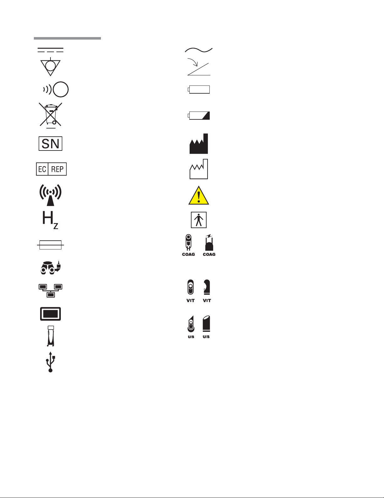
Preface
Direct Current
Equipotential
Ground
Remote Control Reception Indicator
(Foot Control On/ TruLink® Access)
Dispose of Properly
Serial Number
Authorized Representative
in the European Community
Non Ionizing
Electromagnetic
Radiation
Frequency in Hertz
Alternating Current
Foot Control
Battery
Battery Condition Indicator
Manufacturer
Date of Manufacture
Caution: Consult
Accompanying Documents
Type BF Applied Part
Fuse
Camera Recorder
Ethernet
Monitor
Stellaris®
Vision Enhancement System .
USB
or
or
or
Ω
VA
A
Coagulation
Pneumatic Vitrectomy
Ultrasound
Ohms
Volt Amps
Amperes
Preface-4 110017243EN Rev. H
Page 7
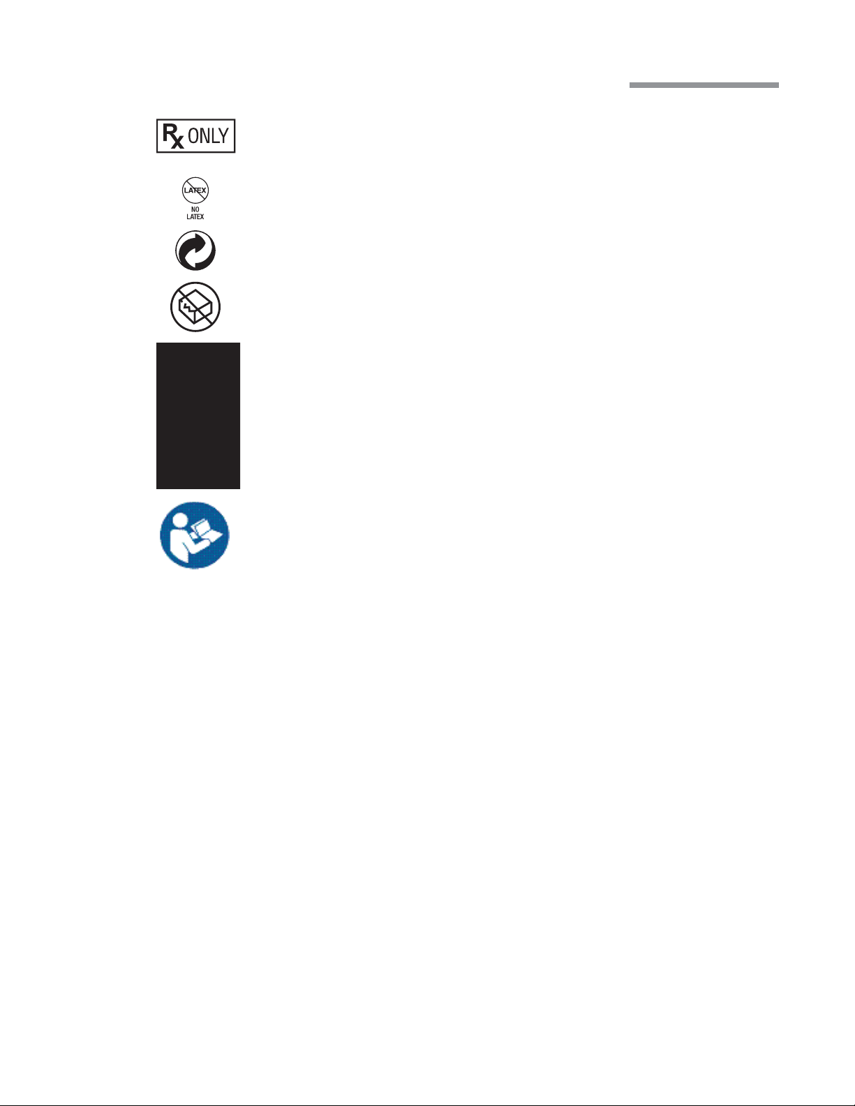
21CFR801.109(b)
Caution: Federal (US) law restricts
this device to sale by or on the order
of a physician
No Latex
Member Green Dot Scheme
Do Not Use if Package is Damaged
System transport information, refer
to page1-12 .
Preface
Caution: Consult
Accompanying Documents
Preface-5 110017243EN Rev. H
Page 8

Preface
Preface-6 110017243EN Rev. H
Page 9

Table of Contents
1. Getting Started
1.1. System Description ................................................................................................................................ 1-2
1.2. Setting Up Your System .......................................................................................................................... 1-3
1.3. Moving Your System to Another Location ............................................................................................ 1-11
1.4. System Components ............................................................................................................................. 1-12
2. User Interface
2.1. Basic Interface Controls ......................................................................................................................... 2-1
2.2. Surgical “More Screens” ........................................................................................................................ 2-6
2.3. Surgical Screen Layout ......................................................................................................................... 2-14
2.4. Foot Control ......................................................................................................................................... 2-18
3. Customizing Your System
3.1. Manage Settings ..................................................................................................................................... 3-3
3.2. System Setup ........................................................................................................................................ 3-18
3.3. System Con guration ........................................................................................................................... 3-21
3.4. System Calendar ................................................................................................................................... 3-22
3.5. TruLink® Remote Access .................................................................................................................... 3-23
3.6. Customization Levels ........................................................................................................................... 3-25
4. Detailed Reference
4.1. Computer Unit ........................................................................................................................................ 4-1
4.2. System Console ...................................................................................................................................... 4-2
4.3. IV Pole .................................................................................................................................................... 4-5
4.4. Remote Control ...................................................................................................................................... 4-6
4.5. Advanced Vacuum System Fluidics ........................................................................................................ 4-7
4.6. Advanced Flow System Fluidics .......................................................................................................... 4-12
4.7. Irrigation/Aspiration Setup ................................................................................................................... 4-14
4.8. Vitrectomy Function ............................................................................................................................. 4-15
4.9. Ultrasound Function ............................................................................................................................. 4-20
4.10. Coagulation Function ........................................................................................................................... 4-27
4.11. DigiFlow™ Pressurized Infusion Function .......................................................................................... 4-30
110017243EN Rev. H
Page 10

Table of Contents
5. Cleaning and Sterilization Requirements
5.1. Stellaris® Vision Enhancement System Routine Cleaning ..................................................................... 5-2
5.2. Bipolar Coagulation Accessories ............................................................................................................ 5-3
5.3. Advanced Flow Fluidics Transducer ...................................................................................................... 5-4
5.4. Irrigation and Irrigation/Aspiration Handpieces ..................................................................................... 5-5
5.5. Phacoemulsi cation Handpiece and Accessories ................................................................................... 5-8
5.6. Special Instructions for United Kingdom Users ................................................................................... 5-12
5.7. Cleaning the MMC ............................................................................................................................... 5-14
6. Setup
6.1. Setup Instructions ................................................................................................................................... 6-2
6.2. Connections and Setup ........................................................................................................................... 6-2
6.3. Multimedia Center (MMC) (optional accessory) ................................................................................... 6-3
7. Troubleshooting and Maintenance
7.1. User Troubleshooting ............................................................................................................................. 7-1
7.2. Power Issues ........................................................................................................................................... 7-1
7.3. Informational and Warning Messages .................................................................................................... 7-3
7.4. Troubleshooting the MMC ................................................................................................................... 7-19
7.5. System Con gurations, Modules, Accessories and Packs .................................................................... 7-21
8. Service and Warranty
8.1. Service Information ................................................................................................................................ 8-2
8.2. Environmental Protection ..................................................................................................................... 8-12
8.3. Warranty Information ........................................................................................................................... 8-13
9. Specifications
9.1. Environmental and Physical Speci cations ............................................................................................ 9-1
9.2. Primary System Speci cations ............................................................................................................... 9-8
110017243EN Rev. H
Page 11

1 Getting Started
Getting Started
This chapter is for people who have used this type of ophthalmic Vision Enhancement System before and want
to use the system without reading large portions of the manual.
WARNING:
WARNING:
WARNING:
WARNING:
WARNING:
Implantable defibrillators present a risk of injury if triggered by a fibrillatory event during
intraocular surgery, due to involuntary motion by the patient. Patients being considered for
intraocular procedures must be questioned to determine if they have such a device and, if so,
the defibrillator manufacturer must be consulted to determine the appropriate action.
Electromagnetic interaction between the phacoemulsification (phaco) handpiece and
an implanted cardiac pacemaker is unlikely, but cannot be ruled out. Patients should be
questioned to determine if they have such an implant and, if so, the manufacturer of the
implant should be consulted to determine the proper course of action.
Patient not to come in contact with earthing metal parts.
Avoid skin-to-skin contact.
Grounding reliability can only be achieved when the equipment is connected to an equivalent
receptacle marked “Hospital Only” or “Hospital Grade.”
WARNING:
To avoid risk of electric shock, this equipment must only be connected to a supply mains with
protective earth.
Operator's Manual 1-1 110017243EN Rev. H
Page 12

1 Getting Started
1.1. System Description
The Stellaris® Vision Enhancement System has a modular design which enables it to be upgraded to take
advantage of advances in technology. The system consists of a main housing unit which contains a user interface
screen and the surgical modules, and a Foot Control, infrared remote control, handpieces, and other accessories.
Note:
Do not use StellarisPC Vision Enhancement System posterior or combined packs on a Stellaris
system.
IV Pole
User Interface Screen
System Switch
“ON/OFF”
Pneumatic Anterior
Vit Acuator
Handpiece Connectors
Fluidic Module
Surgical Tray
Expansion Space
Drawer
One-Touch Wheel Locking
1-2 Operator's Manual 110017243EN Rev. H
Page 13

1 Getting Started
1.2. Setting Up Your System
DANGER: Do not use in the presence of flammable anaesthetics, disinfectants, aerosol sprays, or in an
oxygen rich atmosphere.
WARNING:
Note:
WARNING:
WARNING:
WARNING:
Before the first use of the Stellaris® Vision Enhancement System , connect the Foot Control as described on
page6-3 .
This system should only be operated by personnel who have been trained and are qualified to
use this system.
Do not add unapproved accessories that modify the effective IV pole height.
Do not manually force the IV Pole downward if the system is on.
Do not modify the pole height or manually force the pole height, as this could cause an
incorrect indication of the bottle height and patient injury.
When using gravity infusion, the ophthalmic irrigation source shall be at or above the
patient’s eye level to avoid patient injury.
The following pages contain an overview for setup and use of your Stellaris® Vision Enhancement System in a
typical cataract surgery. This information is intended for use by someone who is already familiar with this type
of system.
Operator's Manual 1-3 110017243EN Rev. H
Page 14

1 Getting Started
Surgical Drape Setup
Attach the sterile screen drape by placing the drape over the top of the Stellaris® Vision Enhancement System
screen and secure with the adhesive strip to top, not the front, of the display as shown in the illustration below.
Apply Screen Drape Here
Screen Drape
Remote Control Drape
Tray Drape
Turning System On
Plug the power supply cord into the wall.
If desired, connect the Ethernet cable to the port at the bottom of the Stellaris® Vision Enhancement System ,
and the other end to the hospital network port. If you have the optional MMC system, this cable should be
connected to the MMC, and the MMC in turn connected to the hospital network port.
Turn on the switch at the bottom of the system console.
CAUTION:
CAUTION:
Do not turn this switch off until the system has been properly powered down.
Do not disconnect system from power while in use.
1-4 Operator's Manual 110017243EN Rev. H
Page 15

1 Getting Started
Figure1.1. Lower Rear of System.
1.Fuse Holder.
2.Main Power Switch, disconnects system from mains voltage. See IEC 60601-1, paragraph 8.6.7
3.Ethernet Port. 4.Foot Control Backup Cable Port.
5.Power Cord Input. 6.Power Cord Retention Clip. 7. Potential Equalization Connector.
Note: Turning off the Main Power Switch will disconnect the system from mains.
Press the power button on the front of the system, and wait for the screen to come on and the animation to
finish. The front power switch is brighter when the system is off, and dims when you turn the system on.
The Stellaris® Vision Enhancement System performs a self-check each time the power is turned on. The system
automatically checks its configurations for any changes since the last time it was turned on.
Operator's Manual 1-5 110017243EN Rev. H
Page 16

1 Getting Started
CAUTION:
Observe system diagnostic messages when powering up system for first use each day and take
appropriate action if required. Also observe first cassette priming or calibration, phaco/frag
handpiece tuning and/or vitrectomy handpiece testing for correct completion.
Only after the Foot Control has been synchronized to the specific Stellaris® Vision Enhancement System (see
page6-3 ), may you use wireless communication.
Note:
The out-of-factory Wireless System Setup is “Disabled.” Software upgrade will also reset
the Wireless System Setup to “Disabled.” See System Setup Instructions ( Chapter3 ) to
configure Foot Control to wireless operation.
If you are going to use the Foot Control in wireless mode, ensure the Foot Control battery is charged, then hold
down any button on the Foot Control until the green ready light comes on, indicating that communication has
been initiated. This light will turn solid green when full communications have been established.
When the system check is completed following system power-up, the Select Surgeon screen will appear.
Note:
Following system shut down, wait a minimum of 15seconds before restarting the system. The
system is fully shut down after the front panel power button light changes from dim to bright.
1-6 Operator's Manual 110017243EN Rev. H
Page 17

1 Getting Started
Select Options
Touch the surgeon’s name on the list that appears, and it will be highlighted. Then select Confirm to load the
parameters for that surgeon and advance to the Setup Screen .
To setup a new surgeon instead of using an existing one, select Create New to setup a surgeon preference file
for a new surgeon, using parameters from an existing surgeon.
Setup Screen
The Setup Screen allows you to set certain procedure parameters, and prepare the system for surgical
procedures.
If desired, select Select Room and choose the case number, number of operating rooms being used by the
surgeon, and the particular operating room to be used.
If desired, select Select Case and choose the specific technique, needle, grade and pathology for the current
procedure.
Advance to open pack step by selecting Open Pack Insert Cassette from the clock menu.
Uninterruptible Operation of Your System
Some Stellaris models may have a 60-second memory back-up battery. This battery is not considered a
UPS (uninterruptible Power Supply) as it only sustains the software but is not sufficient to power surgical
functions. If the user of the Stellaris® Vision Enhancement System requires continued operation during power
main interruptions, it is recommended that the Stellaris® Vision Enhancement System be powered from an
uninterruptible power supply.
All new Stellaris systems and Power modules manufactured after November 2009 will cease to have memory
back-up battery function.
Note:
In the event the power source is interrupted causing the system to shut down, remove handpiece
from the eye safely and pinch off irrigation clamp to stop fluid flowing into the cassette.
To Start a New Procedure
Note: Ensure tube set connection is secure when connecting to the handpiece and system.
The Stellaris® Vision Enhancement System is user-friendly, and will highlight whichever step is next in a
typical procedure. The steps shown on the display screen will vary slightly depending on which optional
features are installed on your machine. On-screen instructions take precedence over information in this manual.
Operator's Manual 1-7 110017243EN Rev. H
Page 18

1 Getting Started
Note:
1. Setup Fluid Collection System
Open disposables pack and connect fluid collection system.
The system will automatically conduct a vacuum sensor and calibration check. Wait until the progress
bar shows successful completion to proceed. If the system does not pass, corrective actions will be
suggested.
Ensure sufficient volume of irrigation solution is available for the procedure. The level should be
monitored during the procedure.
• If using a vacuum system, insert the fluidics cassette all the way in and hold until it is
automatically captured by the system. The cassette housing backlight will stop blinking and turn
solid when the system captures the cassette.
For surgical techniques that uses high vacuum settings please use vacuum-based packs containing
the StableChamber® tubing to increase holdability (higher vacuum levels) while maintaining
followability (controlled flow).
• If using a flow system, insert the Fluidics Cartridge and select Close Drawer .
1-8 Operator's Manual 110017243EN Rev. H
Page 19

1 Getting Started
2. Connect the accessories to the system for either an ultrasound or vitrectomy procedure.
The steps needed to setup for a surgical procedure are Spike Bottle, Connect Tubing, Plug-in Handpiece,
Attach Needle, Attach Sleeve, and Fill Test Chamber, as detailed below.
Note:
a. Spike the Balanced Salt Solution bottle and hang it at the desired bottle height.
b. Connect the irrigation and aspiration tubing to the appropriate (phaco or vitrectomy) handpiece,
c. Attach the ultrasound handpiece needle.
d. Attach the irrigation sleeve.
e. Fill beaker and test chamber and attach the test chamber to the handpiece. The irrigation pinch
For detailed instructions, select Show Me Steps Ultrasound or Show Me Steps Vitrectomy and a tabbed
screen will appear, detailing the required steps and showing animations of how to perform each step.
If a linear coagulation in setup is enabled or a Foot Control button is programmed for
coagulation, begin by plugging in the coagulation cord.
Additional step if pressurized infusion is used: Connect the Air Tubing Line (D4600A) to the vent
port at the bottle spike and the other end with air filter to the Stellaris® air output connector.
Switch on the air pump from the system setup screen, the control is at the upper right hand of the
screen. The output connector will remain lit when it is at commanded pressure, and blink on and
off when it is not at the commanded pressure.
and plug the handpiece into the Stellaris® Vision Enhancement System . The connector will flash
until the handpiece is connected, and then will remain solidly lit.
valve shall be opened when this step is displayed.
WARNING:
The animations illustrate the steps but do not represent sterile technique.
Operator's Manual 1-9 110017243EN Rev. H
Page 20

1 Getting Started
Advance to Surgery Phase
WARNING: Inadvertent activation of functions that are intended for priming or tuning handpieces while
the handpiece is in the eye can create a hazardous situation that could result in patient injury.
When the fluidics collection device has been attached and all accessories, tubing and handpieces have been
connected, the system will automatically advance to the Prime and Tune phase. This step will be highlighted
on the clock menu.
• If you are performing an ultrasound procedure, select Prime and Tune from the menu on the left side
of the screen.
• If you are performing a vitrectomy procedure, select Prime from the menu on the left side of the
screen.
The selected action will begin, and the progress bar at the bottom of the screen will show when it is completed.
If the system does not pass, the system status screen will suggest corrective action.
Once the system setup has completed successfully, the system will automatically move to the main surgical
screen. Manually selecting Advance to Surgery produces the same result.
Note:
If the system is not primed and tuned, the aspiration and phaco functions will be unavailable.
Using Your System in Surgery
Default parameters and settings are saved in the surgeon preference file, but can be modified during a procedure
using the on screen controls and surgical More Screens (see page2-6 ).
Your system is now ready for the surgical procedure.
For irrigation/aspiration procedures, select I/A and connect the I/A handpiece to the tube set, replacing the
phaco handpiece.
Surgical Procedure Conclusion
Select End from the clock menu. You must confirm that you are ready to end the case and eject the fluid
collection device, and you will be reminded to close the pinch valves.
Note:
The system will then advance to the End of Case screen, lower the IV Pole, and eject the vacuum fluidics
cassette or open the flow module drawer.
Make sure to close the Irrigation Clamp on the Administration Tube Set before ending a
procedure or overflow may occur.
1-10 Operator's Manual 110017243EN Rev. H
Page 21

Remove the fluidics collection device.
1 Getting Started
Remove all disposables from the system. For assistance, select Show Me Steps Remove Disposables to see a
list of which disposables need to be removed, and animations of how to remove each of them.
Select Next Patient to return to the setup screen and prepare the machine for the next procedure, or select Shut
Down System or press the button on the front of the system to completely power down the system.
CAUTION:
Never turn the power switch off or disconnect the power without proper system shutdown.
Equipment damage can occur.
If you have the TruLink® option enabled and have selected Shut Down System you will be asked to confirm
the system shutdown. The system will then ask if you want to upload system data to the Enterprise Server.
Ensure the Ethernet cable from the port at the bottom of the Stellaris® Vision Enhancement System to the
hospital network port is connected before attempting to upload data. The system will send diagnostic data (no
patient data is transferred), then shut down when complete.
At the end of the surgical day, make sure to recharge the Foot Control, as described on page2-27 .
Operator's Manual 1-11 110017243EN Rev. H
Page 22

1 Getting Started
1.3. Moving Your System to Another Location
WARNING: Do not transport or move your system from room to room or up an inclination unless you
have followed the steps below.
This unit is designed to provide mobility within the environment of the operating room.
Care must be taken as to avoid sloped floors greater than 5degrees angle during use.
Before transporting the unit from room to room or for any more extensive moving, follow the basic safety
instructions:
If you want to move your system to another location, follow the steps as listed below.
1. Power down normally by selecting “Shut Down” from the end of case
screen or pressing and holding the front button for at least 8seconds,
ensuring the IV pole is fully retracted.
2. Remove any objects from mat on top of unit.
3. Store the tray all the way in the unit’s tray receptacle.
4. Fully close the front drawer.
5. Roll the power cord in its proper hooks at the rear end of the unit.
6. Place the Foot Control on its dedicated hook, at the rear end of unit.
7. Remove the bottles and tube sets from the unit’s pole hanger and store
separately from the unit.
8. Make sure no objects such as air hose, electrical cord, video cables,
etc... lie in the moving path.
Your system is now ready to be moved to a new location.
Note:
Do not store anything on top of the system, and do not pull the system by the IV pole.
9. Disengage the front brake lever.
10. Always maneuver the unit using the handle bar designed for this
purpose.
1-12 Operator's Manual 110017243EN Rev. H
Page 23

1 Getting Started
1.4. System Components
The Stellaris® Vision Enhancement System has a modular design which enables it to be upgraded to take
advantage of advances in technology. The system consists of a main housing unit which contains a user interface
screen and the surgical modules, and a Foot Control, infrared remote control, handpieces, and other accessories.
WARNING:
WARNING:
WARNING:
Use only handpieces, cables, and accessories designated by Bausch+Lomb for use with this
system.
Manufacturers of cardiac pacemakers advise against use of bipolar cautery devices on
patients with such implants. When conducting surgery on such a patient, a battery-powered
thermal cautery may be used, or the manufacturer of the pacemaker should be consulted to
determine appropriate steps to take in order to use the bipolar cautery function.
Manufacturers of implantable defibrillators recommend that these devices be temporarily
disabled when using bipolar cautery on patients with implants. The surgeon should determine
if the patient has such a device and consult the manufacturer for appropriate actions.
User Interface Screen
The User Interface Screen is the way the user communicates with the Vision Enhancement System . See page2-1
for details. Technical specifications can be found in Chapter9 .
Operator's Manual 1-13 110017243EN Rev. H
Page 24

1 Getting Started
Stellaris® Vision Enhancement System Console
User Interface Screen
System Switch
“ON/OFF”
Handpiece Connectors
Surgical Tray
IV Pole
Pneumatic Anterior
Vit Acuator
Expansion Space
Fluidic Module
Drawer
One-Touch Wheel Locking
This is the main unit (see page4-2 ), which contains the connections for all handpieces, tray, drawer, Ethernet
connector and system housing. On the rear of the main unit, near the IV Pole, are three buttons that move the
IV Pole up, down or back to the preset height for the current mode of operation. The console also contains the
power supply.
CAUTION:
To prevent loss of data, save data before system shuts down.
1-14 Operator's Manual 110017243EN Rev. H
Page 25

Air Pressure
Output Connector
1 Getting Started
USB Port Access
IV Pole Control Buttons
Cord Wrap Hooks
Foot Control Hook
Ultrasound Module
This module contains five ports for connecting system accessories. The top three ports are active and the bottom
two are reserved for future use.
Ultrasound Function (Phacoemulsi cation)
WARNING: Manufacturers of implantable defibrillators recommend that these devices be temporarily
disabled when using phacoemulsification or systems on patients with these implants. This is
especially important when using pulsed phaco modes of operation. Although the implanted
devices are designed to reject electromagnetic interference, and Bausch+Lomb Vision
Enhancement equipment is designed to minimize such interference, a chance interaction
Operator's Manual 1-15 110017243EN Rev. H
Page 26

1 Getting Started
cannot be ruled out. Patients should be questioned to determine if they have such an implant
and, if so, the manufacturer should be consulted to determine the proper course of action.
The second port is for ultrasound handpieces. These support phacoemulsification procedures in continuous,
pulsed, and burst modes.
Coagulation
The third port is for a coagulation handpiece which provides coagulation power in either Fixed or Linear modes.
See page4-27 for details of use and page9-12 for technical specifications.
Foot Control
The Foot Control contains the Footpedal and four programmable buttons, and provides the main interface
between the user and the Vision Enhancement System for controlling most functions. The Foot Control can be
used in a wired or wireless mode. Specifications are in Chapter9 . See page2-18 for detailed instructions for its use.
Fluidics Function
Each Stellaris® Vision Enhancement System has one fluidics module, either an Advanced Flow or Advanced
Vacuum system. Each fluidics module contains a port for a standard pneumatic vitrectomy cutter.
Advanced Flow Function
This function uses a peristaltic-based pump to provide flow from 1ml/min to 60ml/min, and vacuum levels
from 0 to 650mmHg. The corresponding pack has both irrigation and aspiration tubing and a 500ml fluid
collection bag which fits in a drawer on the front of the Stellaris® Vision Enhancement System . Irrigation on/
off control is provided by an internal pinch valve. Pneumatic vitrectomy supports both a Linear Cut Rate and a
Fixed Cut Rate from 30 to 800 cpm. See page4-12 for details and Chapter9 for technical specifications.
Advanced Vacuum Function
This function uses a vacuum-based pump to control the output vacuum range from 0 to 600mmHg, and uses
a rigid 300ml collection cassette with irrigation and aspiration tubing. Pneumatic vitrectomy supports both a
Linear Cut Rate and a Fixed Cut Rate from 30 to 800 cpm. See page4-7 for details and Chapter9 for technical
specifications.
1-16 Operator's Manual 110017243EN Rev. H
Page 27

1 Getting Started
Air Compressor
The compressor module provides vacuum for aspiration in Advanced Vacuum systems, air pressure for
pressurized infusion and air pressure to drive various pinch valves. See Chapter9 for technical specifications.
Remote Control
The remote control allows control of various surgical functions from a distance. The receiver for the IR
signal is at the bottom of the computer screen. See page4-6 for details of operation and Chapter9 for technical
specifications.
TruLink® Remote Access (optional)
The TruLink Customer Support Network feature improves system reliability by supporting remote diagnostics
and performance analysis. System performance data, but no patient data, is collected by the Stellaris® Vision
Enhancement System throughout the surgical day. Upon system shut down, that information can be sent to
Bausch+Lomb secure servers through an encrypted, point to point connection. This allows Bausch+Lomb
to analyze system performance, help you remotely (where this service is available), and proactively service the
system. Surgeon preference files can also be transmitted, to provide a secure off-site backup.
The Ethernet cable that is used to transfer the data can be permanently connected to the Stellaris® Vision
Enhancement System , or it can be connected at the end of each surgical day just before shutting down, and
then disconnected to move or store the Stellaris® Vision Enhancement System . Upon shutdown, from the “End
of Surgery” screen, the system will prompt you if you would like to “Send data to TruLink”, if in agreement,
please make sure that the Ethernet cable is connected to the designated port of location and follow instructions.
After updating, the system will shut down automatically.
Operator's Manual 1-17 110017243EN Rev. H
Page 28

1 Getting Started
Multimedia Center (MMC) (optional)
The MMC is an optional accessory that provides streaming video on the surgical screen and microscope overlay
capability. The MMC supports NTSC and PAL format composite video and S-video, or a FireWire digital
camera.
Main Switch
Connectors from Stellaris
Connectors from TruLink
Connector Status
Connectors from Microscope Camera
Data is transferred between the MMC and the Stellaris® Vision Enhancement System through an Ethernet
cable that runs from the back of the MMC system to the Ethernet port on the bottom of the Stellaris® Vision
Enhancement System . Whenever the MMC is on and connected and the Stellaris® Vision Enhancement System
is in surgical mode, the current video image will appear on screen in the center of the Clock Menu . You can
touch the video image itself to toggle between small and large display sizes. You can also touch the outer
edge of the video display to toggle between the video display itself and an animation showing the effect of the
handpiece in the eye for the currently selected phase.
If the system has the optional MMC, the TruLink® Remote Access can be activated by connecting the Ethernet
port on the MMC to a designated Internet-enabled network connection and enabling the Trulink data download
upon shutdown or Remote Access (if available in your area) function on the Stellaris® Vision Enhancement
System .
Note:
Off-the-shelf Ethernet cable may be used with the Stellaris® Vision Enhancement System to
establish or restore connections.
Note:
The MMC is not intended for diagnostic purposes.
Before installing the Multimedia Center, please take note of the following:
• Multimedia Center must be installed outside of the sterile field.
• Do not place Balanced Salt Solution bottle or other containers of fluid on top of the Multimedia Center.
• AC power source for the Multimedia Center must have a Ground Fault Interrupt.
1-18 Operator's Manual 110017243EN Rev. H
Page 29

2 User Interface
User Interface
This chapter introduces you to the operating controls, displays and terminology used in the Stellaris® Vision
Enhancement System .
2.1. Basic Interface Controls
Spin Button
Pressing one of the arrows will increase (up) or decrease (down) a value to set a system parameter. The current
setting is displayed inside the spin buttons. Pressing the displayed number will take you to the numeric keypad
(see page2-3 ) so you can enter an exact number only if the surgical function is not currently in use.
Push Bar
This is a single button control which displays a command, and initiates that action when you select it. No value
is associated with this control and holding it down performs no additional function.
Operator's Manual 2-1 110017243EN Rev. H
Page 30

2 User Interface
Option List
The Option List allows you to select an option. A small + next to a setting indicates that additional choices are
available, and selecting the currently displayed option will bring up a list. Only one option can be selected at a
given time. Selecting one option automatically deselects others.
Test Tube Display and Control
This type of control allows you to set the limits of a system parameter. The actual value is displayed above the
tube, and the allowable minimum and maximum values are shown beside the tube. The current setting may
be changed by selecting and dragging the slider ring. The slider ring may not be positioned below the current
setting minimum value. The minimum value may be changed with the surgical function More Screen.
Maximum Limit
Current Max Settings
Function Minimum
Actual Value
Slider Ring
2-2 Operator's Manual 110017243EN Rev. H
Page 31

2 User Interface
Progress Bar
This graphic shows the progress of a procedure.
Numeric Keypad
Selecting a number on a spin control button brings up the numeric keypad. The keypad allows you to rapidly
enter numerical surgical settings or change settings. Numbers are entered by touching the numeral, then select
Enter to make the change. When a surgical function is active, the keypad for settings associated with that
function will be removed or disabled.
Operator's Manual 2-3 110017243EN Rev. H
Page 32

2 User Interface
Keyboard
Sometimes you will need to enter alphabetical or numeric data into the Stellaris® Vision Enhancement System .
A keyboard similar to that shown below will appear, and you can touch the characters in order to enter them.
Selecting the back arrow will delete the last character typed, and selecting Clear will delete all characters.
Select Enter when you are done to save the entry and return to the previous screen or it will advance to next
level of programming screen.
Character Lengths
There is a finite number of characters that can be used for certain functions. Refer to the table below:
Function Maximum Characters
Mode 8
Technique 20
Submode 20
Pathology 20
Surgeon 30
Display Format
Selecting this button, shown below, steps that section of the display through multiple levels of complexity. It
appears on the Status Bar Window and the Ultrasound Submode List .
2-4 Operator's Manual 110017243EN Rev. H
Page 33

2 User Interface
Pop-Up Message Window
This type of window appears to display error and warning messages. You should take the appropriate action
before the system will continue. Nothing else can be done on the screen while a pop-up window is on the
screen. The surgeon may be able to continue with the procedure once the error has been rectified.*
* For each message displayed, suggested actions to resolve the condition are displayed. If more than one
suggested action is available, pressing the Next button will cycle through all possible suggested actions.
Operator's Manual 2-5 110017243EN Rev. H
Page 34

2 User Interface
2.2. Surgical “More Screens”
More Screens allow easy access to all system parameters. The exact More Screen options available will
depend on the current state of the system, current programming level, and other system settings. Select the
More Screen Button (shown below) associated with an on screen surgical function to open the corresponding
More Screen .
More Screens are available for the Fluidics (Aspiration and Infusion), Ultrasound, Coagulation, Vitrectomy,
Footpedal, and Audio/Visual functions, and Case Selection options.
Note:
More Screens for the Fluidics, Ultrasound, Coagulation, and Vitrectomy functions are only
available at Display Level 2.
2-6 Operator's Manual 110017243EN Rev. H
Page 35

2 User Interface
Fluidics (Flow and Vacuum) More Screen
The Fluidics More Screen has two tabs, one for Aspiration settings and one for Infusion settings. Select either
tab at the top of the Fluidics More Screen to see options specific to the fluidics system installed on your
system. The specific options available will depend on what accessories you have on your system, the current
programming level, and other system settings.
The Aspiration Tab can show the current mode, vacuum settings, flow settings, vacuum response setting,
venting method, and Foot Control Mapping .
The Infusion Tab can show the current Infusion mode, IV Pole Height (actual, preset and maximum), Balanced
Salt Solution Container Type, Patient Eye Level, Irrigation Delay and Pressurized Infusion (enabled/disabled,
pressure settings, pump on/off status).
The actual IV Pole height is the current distance between the aspiration port and the mid-point of the viewing
port of the Balanced Salt Solution drip chamber. The maximum IV Pole height is the highest setting the IV Pole
will be allowed to reach, usually determined by the ceiling height and set at time of system installation. A zero
level bottle hanger (BL4363) is an optional accessory that allows the Balanced Salt Solution drip chamber to be
level with the aspiration port.
Operator's Manual 2-7 110017243EN Rev. H
Page 36

2 User Interface
Ultrasound More Settings
The Ultrasound More Screen shows the current modulation status and power level. Depending on which type
of ultrasound and programming level you are currently using, you may also see number of pulses per second
(PPS), duty cycle (DC), burst duration (BD), and pulse interval (PI), waveform type, waveform depth and
waveform duration may also be shown. You can adjust any of these settings.
2-8 Operator's Manual 110017243EN Rev. H
Page 37

2 User Interface
Coagulation More Settings
The Coagulation More Screen shows the current minimum and maximum power levels, and the Foot Control
Mapping mode. You can adjust either power level setting.
Vitrectomy More Settings
The Vitrectomy More Screen shows the current settings for the minimum and maximum CPM (cuts per
minute). You can adjust either setting. The current Foot Control Mapping is also shown.
Note: Foot Control mapping available on Programming Level2 and 3 only.
Operator's Manual 2-9 110017243EN Rev. H
Page 38

2 User Interface
Footpedal More Settings
The Footpedal More Screen has three tabs that allow you to view and edit Settings, Regions, and the Status of
the Foot Control. These functions are described in detail in the Foot Control section (see page2-18 ).
The Settings Tab shows the current status of the Foot Control buttons, right or left foot operation, Dual Linear
Control, Mode Change Control, Next U/S (Ultrasound) Modulation on Yaw, Reflux Type, and Fixed Coag
Power. Editable functions are highlighted with a blue or gray background marked with “+”.
The Regions Tab shows the current settings for the footpedal pitch regions and detent options. You can modify
the starting depression position for each region.
2-10 Operator's Manual 110017243EN Rev. H
Page 39

2 User Interface
The Status Tab shows the current status of several footpedal options, including communication status, battery
status, and signal strength.
A/V More Screen
The A/V More Screen allows you to change many aspects of the audio and video display. Each tab allows you
to change the settings and configuration for aspects of the display.
The Audio Tab controls the master volume for the system, as well as the specific tone and volume used for
each of the following events: Irrigation, Vacuum, Occlusion, Ultrasound, Coagulation, Vitrectomy, and Alert.
The selected tone will be played when that function is active, and the frequency of the tone will change with the
value of the function.
Select the tone you want to change, then use the menu and arrows on the right side of the screen to select the
tone used for that condition, and the volume at which the tone will be played. Only tones not currently in use for
another condition will be displayed.
Voice Confirmation can also be enabled or disabled through this tab.
Operator's Manual 2-11 110017243EN Rev. H
Page 40

2 User Interface
The Screen Display Tab control allows you to adjust the screen brightness, change the display format level,
select the system language, and view the programming level.
The Video Overlay Tab allows you to select the language to be used for video overlays.
You can also set whether or not the system will combine Video Overlay Format information, such as U/S
Averages, settings, and case information. By default, the U/S data is shown as three separate lines on the video
overlay. If the U/S combine option is set to Ye s , the display will appear on one line, which will step through the
three values. Similarly, settings are normally displayed on four lines, and case information on two lines, but if
the combine option is set to Ye s each will appear on one line that will step through the values.
Finally, you can set the video overlay overscan in one degree increments from 0% to 5%.
2-12 Operator's Manual 110017243EN Rev. H
Page 41

2 User Interface
The Remote Control Tab of the A/V More Screen allows you to enable or disable the remote control.
Case More Settings
The Case More Screen shows the case number, total number of rooms in which the Stellaris® Vision
Enhancement System will be used, the room number in which the system currently resides, as well as the
technique, needle, grade and pathology for the current case. Select the parameter to be changed, and then select
the new setting from the option list. When you have made all the desired changes, select Close and the change
will take effect.
You can select Save Settings to have the new settings overwrite the current surgeon’s preferences, and be stored
in the main preferences file.
Note:
Selecting Save Settings here will save all changes made through any aspect of the user
interface. You can select Reset Averages to clear the average values and elapsed times for the
surgical functions for this case.
Operator's Manual 2-13 110017243EN Rev. H
Page 42

2 User Interface
2.3. Surgical Screen Layout
Note: Voice confirmation (if enabled) responds to Foot Control and remote operation and on-screen
buttons.
The main surgical screen can appear in one of two formats. The default format is set as a surgeon preference. To
switch between levels, click the A/V More Button (located at the top of the screen), select the Screen Display
Ta b , then select the desired Display Format Level .
Level 1 Display
At Level 1, only the basic controls are displayed.
Note:
More Screens for the Fluidics, Ultrasound, Coagulation, and Vitrectomy functions are only
available at Display Level 2.
Clock Menu
The round Clock Menu in the middle of the screen can display up to 12 phases—eight normal phases and four
exceptions. The exceptions appear on the left side of the clock menu, against a darker background. These are
user-defined to be any mode type (Irrigation only, Ultrasound, Irrigation/Aspiration, Electric Vit, Pneumatic Vit
or Coagulation). The Setup and End are the system function keys in the clock menu to change from surgical
display screen to Setup and End screens.
2-14 Operator's Manual 110017243EN Rev. H
Page 43

2 User Interface
If you have the optional MMC system installed, the center of the Clock Menu will show the video from the
microscope camera, when video is available. You can select the video itself to switch between small and large
video display formats. You can select the edge of the video to display an animation showing the effect of the
handpiece on the eye for the current surgical phase.
See Chapter3 for details on customizing your system.
IV Pole
The upper right corner of the screen also displays the current setting for the IV Pole (on the bottle), as well as
the preset value (above the bottle). You can use the up and down arrows to change the height, and the IV Pole
will automatically move up and down to match the setting.
The Preset value is a pre-programmed value to which you can jump quickly, simply by selecting it on the
screen. Different surgical modes may have different preset values. You can change the preset value for the
current session by opening the Fluidics More Screen (see page2-7 ) and selecting the Infusion Tab .
The On/Off button controls the continuous irrigation function, by opening or closing the irrigation pinch valve
in the fluidics system. If the irrigation control is turned off, the function will still be managed by the Foot
Control when the footpedal enters Region1, irrigation will commence.
Fill
Button
Selecting the fill button opens the pinch valves in the fluidics system for a fixed period of time. This function is
useful for filling surgical beakers without overflow. The button shows the current state of the fill system (On or
Off). You can select it to toggle to the other state.
Air Pressure
If Pressurized Infusion function is programmed in the surgeon file, the upper right corner of the screen displays
the current setting of air pressure when the pump is not running. When the pump is switched on, the same area
will display the actual output pressure. Below the setting display, there is an on/off button to control the air
pump operation.
Operator's Manual 2-15 110017243EN Rev. H
Page 44

2 User Interface
Ultrasound, Coagulation or Vitrectomy
The lower right corner displays either the Ultrasound, Coagulation or Vitrectomy status, depending on which
mode is currently selected from the clock menu. The current setting is shown in the large spin control, with a
green background for ultrasound, yellow background for vitrectomy, and purple background for coagulation.
The actual value is displayed in a small grey circle below the spin control.
When ultrasound is active, an option list control appears in the lower right corner, and selecting the small +
allows you to select from a list of preprogrammed ultrasound submodes. If you select pulsed ultrasound, the
pulse per second (PPS) and duty cycle (DC) spin controls appear if the display option button is selected.
Vacuum
The upper left section of the screen shows the maximum vacuum or vacuum limit setting in a spin control
button, with the current actual value shown below it.
Flow
The lower left corner of the screen shows the maximum flow setting, if enabled, with the current actual flow
value below it. The volume of fluid in the collection device is also displayed here.
Footpedal and Coagulation
The current footpedal status is displayed in the middle of the bottom of the screen. The current pitch region (1,
2, or 3) is shown, and the circles around the top indicate yaw position. The Footpedal More Button brings up
a More Screen that allows you to change settings on the footpedal. See page2-10 for details on changing these
settings. See note on page2-33 .
If one of the Foot Control Buttons has been programmed to control coagulation, a small Coagulation spin
control will appear just to the left of the Foot Control display, showing the current maximum power setting for
the coagulation function.
Case Window
At the top of the screen, a status bar display shows the name of the surgeon currently working, as well as the
current case number. Selecting the Display Format Button (see page2-4 ) repeatedly shows progressively more
detail.
2-16 Operator's Manual 110017243EN Rev. H
Page 45

2 User Interface
Level 2 Display
At Level 2, more detailed information is added to each display about the current value of each system. In
addition to the spin control buttons that are present in the Level 1 display, the Level 2 display adds a test tube
display and control (see page2-2 ). The current value of the function is displayed at the top of the tube, and a slider
ring on the tube can be used to change the setting.
Operator's Manual 2-17 110017243EN Rev. H
Page 46

2 User Interface
2.4. Foot Control
The Foot Control is the main interface between the surgeon and the Stellaris® Vision Enhancement System .
The surgeon can control most of the available functions from the Foot Control. The Foot Control can be
connected through a physical cable, or through a wireless Bluetooth connection. When the Foot Control Cables
are not in use, make sure to install the attached protective caps into the cable ports.
This device complies with Part 15 of the FCC (U.S. Federal Communication Commission) Rules. Operation is
subject to the following two conditions: 1) this device may not cause harmful interference, and 2) this device
must accept any interference received, including interference that may cause undesired operation.
Placement of Foot Control During Storage
2-18 Operator's Manual 110017243EN Rev. H
Page 47

2 User Interface
The Foot Control contains an internal, rechargeable battery. The battery cover has the battery symbol on it.
The battery needs to be charged overnight prior to initial wireless use, and if the system is idle for more than
seven days, refer to the battery charging options section on page2-27 .
Foot Control Battery Installation Guide:
1. Place Foot Control upside down on a flat, dry surface.
2. Open battery door by pressing the targets on the door toward the battery compartment and turn the two
latches 90 degrees away from the center.
3. Remove battery with two fingers holding on to the battery.
4. Before installing the replacement battery, check battery electrical contacts to ensure they are clean and
free of contamination.
5. Install new battery.
6. Press the door toward the compartment and engage door latches to securely close battery door.
Note:
Note:
Be sure to securely close battery door.
A battery must be installed in the Foot Control at all times, while operating either wired or
wireless, to insure proper operation.
LED Symbol for Battery on Foot Control
Battery compartment with recess (arrows) to
facilitate battery replacement
Operator's Manual 2-19 110017243EN Rev. H
Page 48

2 User Interface
Note:
The out-of-factory Wireless System Setup is “Disabled.” Software upgrade will also reset the
Wireless System Setup to “Disabled.”
To setup wireless operation, follow steps below:
1. Select “Programming” from Setup or “Select Surgeon” screens.
2. Select “System Setup” from the Programming screen (screen image below).
3. Select “Foot Control” tab from the “System Setup” screen (screen image below).
4. Select Wireless “Enabled” or “Disabled” to configure Foot Control connection mode.
2-20 Operator's Manual 110017243EN Rev. H
Page 49

2 User Interface
Note:
The system setup is for enabling wireless functionality, it does not affect the wired functionality.
The wired option is always available and active when connected.
Note:
System will disable wireless operation once it detects loss of wireless communication at
setup and surgery screens. Once wireless connectivity is lost, the wireless opperation must be
manually reconfigured using the system setup screens.
Note:
The system will disable wireless operation when the battery is replaced or removed while system
is in surgical or setup screens. To configure system to wireless operation, see section on Wireless
Foot Control System Setup, page2-20 .
The first time a Foot Control is used, it must be connected via the back up cable to set the configuration. Once
this is set, the Foot Control will only communicate wirelessly with that specific system. To begin wireless
operation, make sure the Stellaris® Vision Enhancement System is on, then press any Foot Control Button and
wait up to ten seconds for communication to be established.
The ready light, identified by the symbol below, will turn solid green when the Foot Control is communicating
wirelessly with the Stellaris® Vision Enhancement System . During operation when system is not detecting
Foot Control wireless connection; the system will disable wireless operation. This happens when the system
is in setup and surgery screens. To resume wireless operation, refer to the Foot Control Wireless System setup
section.
LED Symbol for Ready on Foot Control
Operator's Manual 2-21 110017243EN Rev. H
Page 50

2 User Interface
dal Pitch
When not in use, the Foot Control can be stored on the back of the Stellaris® Vision Enhancement System .
In some operating configurations the surgeon can change surgical phases using the Foot Control.
Back-Up Power Cord Input
Left Toe Button
Left Heel Button
Left LED (Battery)
Pedal Offset
Adjusment Switch
Right Toe Button
Foot Pedal
Indicator Lights
Right LED (Wireless)
Right Heel Button
Pe
Adjustment Knob
Tension
Battery Compartment Door
2-22 Operator's Manual 110017243EN Rev. H
Page 51

2 User Interface
Foot Control Status and Wireless Signal Strength Meter Display
The status of Foot Control operation is represented by an icons display at the lower portion of the screen above
the foot pedal activation status indicator. Wired connectivity is represented with a cable icon and the wireless
connectivity is indicated with a signal strength meter icon. See table below:
Display Type Foot Control Setup Status Action
Wired
(Wireless disabled)
Wired
(Wireless disabled)
Wireless System NOT detecting
System detecting wired
Foot Control
System NOT detecting
wired connection.
Possible cause:
Foot Control cable not
connected
wireless connection
signal
Possible cause:
1. Foot Control wireless
function has not been
activated.
2. Wireless connectivity
not functioning due to
battery issue
No action required
Check Foot Control cable
connection.
If Wireless System
Setup is on “enabled,”
wireless connection will
be activated momentarily
when system detects loss
of wired connection.
The wireless signal
strength icon will be
displayed indicating
system is now in wireless
operation.
1. Initiate wireless Foot
Control connectivity
by pressing one of the
foot control buttons
momentarily, the left
LED will light up.
2. Check battery
if Foot Control
wireless function
not established after
Step1.
Operator's Manual 2-23 110017243EN Rev. H
Page 52

2 User Interface
Display Type Foot Control Setup Status Action
Wireless System detecting
Excellent signal strength
Wireless System detecting Good
signal strength
No action required
No action required
Wireless System detecting
Moderate signal strength
Wireless System detecting Low
signal strength
No action required
No action required
2-24 Operator's Manual 110017243EN Rev. H
Page 53

Display Type Foot Control Setup Status Action
Wireless (System
disabled wireless setup)
System lost wireless
connection signal during
procedure.
System will automatically
configure to wired
operation.
The icon remains
until connected with
Foot Control cable or
manually re-configures
system to wireless
configuration.
Connect Foot Control
backup cable to resume
operation.
Note:
System will remain in
wired configuration
the next time system is
powered up. To configure
system to wireless
operation, see section on
Wireless Foot Control
System Setup, page2-20 .
2 User Interface
Note:
Note:
The system will disable wireless operation when the battery is replaced or removed while system
is in surgical or setup screens. To configure system to wireless operation, see section on Wireless
Foot Control System Setup, page2-20 .
Irrigation will be turned ON and other functions will be disabled when the system does not
detect Foot Control connectivity in surgical mode. Irrigation can be turned OFF from the touch
screen.
Operator's Manual 2-25 110017243EN Rev. H
Page 54

2 User Interface
Battery Management
This symbol on the battery indicates that the product must be disposed of separately and
safely. Therefore, it is your responsibility to dispose of this waste equipment by handing
it over to a designated collection point or organization that specializes in the recycling of
waste electrical and electronic equipment. The separate collection and recycling of your
waste equipment at the time of disposal will help conserve natural resources and ensure
that it is recycled in a manner that protects human health and the environment. For more
information about where you can drop off your waste equipment for recycling, please
contact your local recycling office or electronic waste hauler.
CAUTION:
The battery, when fully charged, will last for 12hours. You may rely on a single battery, or choose to keep one
charging in a battery charging cradle (BL4393 shown below) while the other battery is being used.
Do not expose the battery to any fluids.
2-26 Operator's Manual 110017243EN Rev. H
Page 55

2 User Interface
Battery Charging Options
Note: The battery should be removed from the Foot Control if the system is to be idle for more than
seven days.
Note:
Note:
The Foot Control Battery should be charged whenever the system is not in use. Any one of three methods can
be used to charge the battery.
• With the system power cord plugged in to the electric source and the Foot Control connected to the
• The Foot Control can be directly connected to the wall charger. Connect the wall charger cable into the
• With an extra battery and battery charging cradle, you can connect the wall charger cable to the battery
Note:
To maximize performance, the Foot Control batteries (BL4390) should be rotated every two
months. Upon removal, battery must be charged before it’s stored.
Use only Bausch+Lomb supplied wall chargers (BL4391), charging cradles (BL4393),
adapters (BL4392US, BL4392UK, BL4392EU, BL4392AUS, BL4392ROW), and batteries
(BL4390) with the Stellaris® Vision Enhancement System .
system; the battery will be charged if the main power switch is turned ON. This charging method
applies with or without the Graphical User Interface being turned ON.
back of the Foot Control, into the same receptacle used for the backup cable.
charging cradle. A green light indicates the cradle is on, a second light is yellow when charging is in
progress, and green when the battery charging is complete. Once the battery is fully charged, you can
take it out of the cradle and replace the battery in the Foot Control.
When the Foot Control is connected to the wall charger it will not communicate with the system
and cannot be used in surgery.
Note:
To connect backup cable or wall charger to Foot Control, align red dot of the connectors to 12
o’clock position.
Operator's Manual 2-27 110017243EN Rev. H
Page 56

2 User Interface
Note:
The Foot Control is only to be used with wall charger BL4391.
Note: The battery charging cradle MUST be connected to the wall charger to charge the battery.
The wireless communication is disabled when the backup cable is in place.
The Stellaris® Vision Enhancement System will provide a warning message when the battery is nearing the end
of its life. Call your customer service representative to get a replacement battery. See Chapter8 for a list of
local Bausch+Lomb offices.
2-28 Operator's Manual 110017243EN Rev. H
Page 57

2 User Interface
Foot Control Operation
The Foot Control has four buttons and a center footpedal which has two axes of movement, to control two linear
functions simultaneously. The footpedal operates with both the pitch (up and down) and yaw (side to side)
travel. The yaw movement simulates the side switches used on some systems, and can be set and programmed
for left-foot or right-foot users. Reflux (if selected) is always activated by inward yaw displacement. The center
footpedal may be programmed to operate two linear functions simultaneously (Dual Linear control). The control
of linear functions is proportional to the amount of footpedal travel. See page2-33 for description of linear control.
In single linear mode, pitch controls the linear functions selected, and yaw movement provides on/off control
in both directions. In Dual Linear mode, one linear function is controlled by pitch travel, and the other linear
function is controlled by yaw travel. The table on page2-34 shows the possible combinations of linear control.
Left Heel Button
Left LED
(Battery)
Left Toe Button
Right LED
(Wireless)
Right Heel Button
Foot Pedal
Right Toe Button
There are two lights on the Foot Control itself. The light on the right indicates that the wireless connection on
the Foot Control is active. This light will flash until communications are established with the system. When the
light is non-flashing green, the Foot Control is ready to be used wirelessly. The light on the left indicates battery
status, as described in the table below.
Color Status
Green More than one hour of battery life remains
Yellow Battery is charging
Red and Blinking Less than one hour of battery life remains
Operator's Manual 2-29 110017243EN Rev. H
Page 58

2 User Interface
Basic Button Operation
Note: Voice confirmation (if enabled) responds to Foot Control and remote control operation. For
surgical phase changes, voice confirmation also will be activated if changes are made through
the touch screen.
All four buttons on the Foot Control are user programmable. They are initially set in the surgeon preferences
file, and can be modified either through the programming interface (see Chapter3 ), or in some cases through the
Footpedal More Screen (see page2-10 ).
The Footpedal More Screen is used to convey the current footpedal configuration and status to the surgical
team. It is displayed by selecting the Footpedal More Button , which is the below the Footpedal status icon on
the bottom of the Main Surgical Screen .
Footpedal
The footpedal itself, located in the center of the Foot Control, provides two axes of movement and thus allows
simultaneous control of two system parameters. Both controls are programmable with respect to function and
control parameters. In the pitch direction, the footpedal will provide approximately 15° of up/down movement.
In the yaw direction, the center pedal will provide approximately 10° of travel from center in both the left and
right directions, however, the center (home) position may be set to be offset approximately 5° in either direction
as explained on page2-33 . When released, the footpedal will return to the home (up or center) position. The table
on page2-34 shows the possible combinations of control available. The programmable detents provide tactile
feedback to the pitch movement when it moves between different regions.
2-30 Operator's Manual 110017243EN Rev. H
Page 59

2 User Interface
Single Region Pitch Control (one detent position)
The pitch movement is programmed to provide linear control as a function of relative footpedal displacement
(e.g., 0° to 15° down corresponds to 0% to 100% output). An example of single region pitch control is the linear
coagulation function.
Two Region Pitch Control
There are two programmable regions (two detent positions). When programmed for linear control, the pitch
movement is a function of relative footpedal displacement in Region2 (e.g., 5° to 15° down corresponds to 0%
to 100% output). An example is I/A control, where Region1 is for irrigation, and Region2 is for linear vacuum
or flow.
Three Region Pitch Control
There are three programmable regions (three detent positions). When programmed for linear control, pitch
movement is a function of relative footpedal displacement as shown below. An example is single linear
ultrasound phases, where Region1 is irrigation, Region2 is fixed aspiration, and Region3 is linear ultrasound
power.
Operator's Manual 2-31 110017243EN Rev. H
Page 60

2 User Interface
Programmable Yaw Positions
The Foot Control may be set and programmed to give greater linear yaw movement for either right or left
foot operation. Turn the Foot Control over and adjust the Pedal Offset Switch to the left or right for preferred
direction.
• Set and programmed for a right footed operator with the pedal home position offset to the left of center
by approximately 5° to give approximately 15° of motion to the right and approximately 5° of motion
to the left. See Dual Linear Yaw Control below.
• Set and programmed for a left footed operator with the pedal home position offset to the right of center
by approximately 5° to give approximately 15° of motion to the left and approximately 5° of motion to
the right. See Dual Linear Yaw Control below.
• Set and programmed for a right- or left-footed operator with the home position in the center giving
approximately 10° of motion in both directions.
• Pedal offset switch indicator must align with either left, right or center pedal offset position.
Failure to align the indicator appropriately will cause the Foot Control to become inoperable.
Left or right offset position selections strictly follow system software programming for Left or
Right foot operations. E.g.: If system is programmed to right foot operation, the indicator (4)
can only be set to Center (6) or Right Offset Position (7) only. Refer to diagram below.
Pedal Offset Switch Indicator
Pedeal Offset Position-
Left
(for system setup
for left foot operation)
Pedeal Offset Position-
Center
(for system setup
for left or right foot)
Pedeal Offset Position-
Right
(for system setup
for right foot operation)
2-32 Operator's Manual 110017243EN Rev. H
Page 61

2 User Interface
Single Linear Setup
In Vitrectomy Mode , the outward yaw movement provides ON/OFF cutting control. Each successive outward
movement toggles the programmed tool ON or OFF. In ultrasound mode, outward yaw control could be
programmed to toggle between different ultrasound submodes. When the footpedal is released, it returns to the
center position. Inward yaw movement controls reflux.
Dual Linear Setup
The outward yaw movement provides linear control of the programmed function, relative to footpedal
displacement (e.g., 0° to 15° displacement corresponds to 0% to 100% output). When the footpedal is released,
it returns to the center position. Inward yaw movement controls reflux.
Yaw Control of Reflux
The footpedal may be programmed for use with either the right or left foot. Reflux (if selected) is always
activated by inward yaw displacement. For a right foot configuration, reflux is to the left (inward). For a left
foot configuration, reflux would be to the right. Reflux may only be activated when aspiration is not activated.
Yaw Control of Ultrasound Submode
For single linear setup, the ultrasound submode sequence (if programmed) is activated by inward or outward
yaw when the footpedal is in Region2 or Region3. In a Dual Linear Setup , the yaw control of the ultrasound
submode can only be activated (if programmed) by inward yaw when the footpedal is in Region2 or Region3.
Linear Coagulation Control
The control power is varied linearly from preset minimum to the preset limit. Power begins when entering
footpedal position1 and ends at the completion of travel.
Note:
Due to compliance with IEC 60601-2-2, position1 will not start until approximately 35% of
pedal travel is attained in the linear coagulation mode.
Operator's Manual 2-33 110017243EN Rev. H
Page 62

2 User Interface
Center Foot Control for Anterior Modes
Phase Type
Dual Linear
Region Pitch Yaw Out
Control
R1 Irrigation
Disabled
Disabled (with
aspiration control
feature on)
Aspiration on
yaw**
Ultrasound
Aspiration on
yaw & aspiration
control feature
on**
Aspiration on
Pitch**
Dual Linear
Ultrasound***
Disabled
Irrigation/
aspiration
Irrigation Only Disabled R1 Irrigation
Dual Linear
Flow***
R2 Fixed aspiration
R3 Linear ultrasound
R1 Irrigation
R2 Aspiration R2
minimum to fixed
vacuum, vacuum
limit, or flow
R3 Fixed aspiration &
linear ultrasound
R1 Irrigation
R2 Minimum
aspiration
R3 Linear ultrasound
R1 Irrigation
R2 Aspiration R2
minimum to fixed
vacuum, vacuum
limit, or flow
R3 Min. aspiration and
linear ultrasound
R1 Irrigation
R2 Linear aspiration Linear
R1 Irrigation
R2 Fixed Aspiration
R3 Linear U/S
Function
R1 Irrigation
R2 Linear aspiration
R1 Irrigation
R2 Linear Vacuum or
Flow
Next
submode
Next
submode
Linear
aspiration
To max.
aspiration
ultrasound
Linear
Ultrasound
Linear Flow
or Vacuum
2-34 Operator's Manual 110017243EN Rev. H
Page 63

2 User Interface
Phase Type
Dual Linear
Region Pitch Yaw Out
Control
Disabled R1 Irrigation
R2 Linear Aspiration
& fixed vitrectomy
when on
Aspiration on
Pitch**
Vitrectomy
Coagulation Disabled R1 Linear Coagulation
** Only available at Programming Level2.
*** Only available at Programming Level3.
Aspiration on
Yaw***
Dual Linear
Flow***
R1 Irrigation
R2 Linear Aspiration Linear
R1 Irrigation
R2 Linear Vitrectomy Linear
R1 Irrigation
R2 Linear Vacuum or
Flow and Fixed
Vitrectomy when
on
Cutter on/off
Vitrectomy
Aspiration
Linear Flow
or Vacuum
Operator's Manual 2-35 110017243EN Rev. H
Page 64

2
2-36 Operator's Manual 110017243EN Rev. H
Page 65

3 Customizing Your System
Customizing Your System
This chapter explains how to customize your Stellaris® Vision Enhancement System to achieve maximum
flexibility for your operating needs.
Note:
Surgical devices may not be operated during programming.
Each surgeon using the Stellaris® Vision Enhancement System can program the system for their own preferred
operating configuration and instrument parameters. Several default surgeon preference files are pre-loaded on
the system, and you may copy and modify any of them through the Programming interface. You can create,
modify and backup surgeon setting preference files, as well as modify system parameters. The programming
screens are organized as outlined in the diagrams below.
Programming
Manage
Settings
Customize Create Backup Restore Delete
Surgeon
Profile
Technique Foot Control Fluidics Video Overlay
Date / Time System ID Rooms
System Setup System
Configuration
System
Calendar
TruLink
Remote
Access
Technique
Profile
Phase
Profile
Phase Audio/VisualFoot ControlExceptions Fluidics
Foot Control Fluidics Case
Aspiration
Settings
Infusion
Settings
Ultrasound
Settings
Ultrasound
Case
Ultrasound
Waveform
Settings
Vitrectomy
Settings
Coagulation
Settings
Operator's Manual 3-1 110017243EN Rev. H
Page 66

3 Customizing Your System
To program system parameters, select Programming from main clock menu on the Select Surgeon
Programming Level Screen or the Setup Surgical Screen .
The Main Programming Screen will appear, from which you can perform the following functions:
• Manage Settings
• System Setup
• System Configuration
• System Calendar
• TruLink® Remote Access (optional)
Each of these functions is described in more detail below.
At any time, you can select Programming to return to the Main Programming Screen , or Exit Programming
to return to the Select Surgeon Programming Level Screen or the Setup Surgical Screen . In either case, the
Stellaris® Vision Enhancement System will ask if you want to save any changes you have made. Select Ye s to
save your changes and overwrite existing files, and No to discard your changes.
3-2 Operator's Manual 110017243EN Rev. H
Page 67

3 Customizing Your System
3.1. Manage Settings
Select Manage Settings from the Main Programming Screen , and a new screen will appear through which
you can customize an existing surgeon’s file, create a new surgeon preference file by copying from an existing
one, backup files, restore files from a backup, or delete surgeon preference files.
Operator's Manual 3-3 110017243EN Rev. H
Page 68

3 Customizing Your System
Customize a Settings File
To change the settings for a currently existing preference file, select the Customize Tab on the Main
Programming Screen . A list of all surgeon preference files currently loaded on your Stellaris® Vision
Enhancement System will appear. Select the name of the surgeon file to be modified, then select Confirm . The
Surgeon Programming Screen appears, with the file name along the left side of the screen, and seven tabs
across the top (see page3-5 ). These tabs are Profile , Technique , Foot Control Settings , Foot Control Regions ,
Fluidics , A/V , and Video Overlay . Each tab allows you to make global changes to system parameters, and is
described in detail below.
System parameters can be customized at different levels. Global settings take place at the Technique Level .
Technique level settings can be overridden at the phase level. See the table at the end of this chapter for details
on which options can be customized at which level.
3-4 Operator's Manual 110017243EN Rev. H
Page 69

3 Customizing Your System
Customize Pro le
To change the surgeon’s name associated with a settings file, or change the default language, select the Profile
Ta b on the Surgeon Programming Level Screen . Select the surgeon’s name, and use the keyboard interface
that appears to modify the name of that file. Select the language, and a menu of all available languages will
appear, and you can select the one you prefer. You can also enable or disable use of the remote control.
Operator's Manual 3-5 110017243EN Rev. H
Page 70

3 Customizing Your System
Customize Technique
To change the techniques available for a particular surgeon or modify their settings, select the Technique Tab
on the Surgeon Programming Level Screen , and a list of currently defined techniques will appear. You can
select any technique from the current list and use the Move Up and Move Down buttons to rearrange the order
in which they appear. Select Add to add a new technique to the surgeon’s list. Select a technique then select
Delete to remove it, or select Customize to continue programming that technique.
3-6 Operator's Manual 110017243EN Rev. H
Page 71

3 Customizing Your System
To add a new technique to the list, select Add , then select any surgeon from the list that appears, and the
techniques defined for that surgeon will appear. Select a technique and select Confirm to add that technique the
original list.
To change the settings for a particular technique, select the technique, then select Customize . The Customize
Technique Screen will appear, with tabs for Profile , Phases , Exceptions , Foot Control , Fluidics and A/V .
Various parameters may be adjusted through various tabs, as described below.
Note: The programming level may be increased, to allow more control of feature details. However,
once it has been increased it may not be decreased.
Operator's Manual 3-7 110017243EN Rev. H
Page 72

3 Customizing Your System
• Profile Tab —Technique Name, Programming Level (1,2,3)
• Phases Tab —Each technique may include up to eight phases. The Phases Tab shows the name of the
phase, and the mode for that phase (ultrasound, irrigation/aspiration). Phases can be added, deleted, or
re-ordered. They may also be customized, as described below.
• Exceptions Tab —Each technique may include up to four exceptions. Exceptions can be added,
deleted, or re-ordered. They may also be customized, as described below.
• Foot Control Tab —Group or ungroup Foot Control Buttons, enable/disable next ultrasound
modulation on yaw, reflux type (none or continuous).
• Fluidics Tab —Aspiration types (Vac; Vac Modes, Flow: Vac Modes, Flow: Flow Modes, Flow: All
modes), IV Pole Height, Vacuum Response, Venting Method (Air or Fluid), Irrigation Shut-Off Delay
(ms), Pressurized Infusion Function (enabled/disabled), Pressurized Infusion Pump (on/off) and
Pressurized Infusion Settings (mmHg).
• A/V Tab —Display Format (1 or 2), Status Bar Format (1, 2, 3)
3-8 Operator's Manual 110017243EN Rev. H
Page 73

3 Customizing Your System
Customizing Phases and Exceptions
Both Phases and Exceptions can be reordered and customized. Select a phase or exception from the list on the
appropriate tab, and the Customize button will appear. Select Customize , and more options specific to that
function will appear, and can be modified. These can include Phase Information, Foot Control settings, Fluidics
(Aspiration and Infusion), Ultrasound (Ultrasound and Wave Form), Vitrectomy, Coagulation settings. When
you are done making changes, select Exit Programming . The system will ask you to confirm your changes
before exiting.
Operator's Manual 3-9 110017243EN Rev. H
Page 74

3 Customizing Your System
Customize Foot Control
To modify the techniques for the Foot Control, select the Foot Control Tab on the Surgeon Programming
Level Screen . You can set the Foot Control to use right or left foot operation. The Mode Change Control
allows you to set the Stellaris® Vision Enhancement System response when the footpedal is activated and you
change surgical modes. The Detent Control determines what feedback the Stellaris® Vision Enhancement
System will give when changing footpedal regions. Use the Region Spin Control Buttons to change the
percent depression at which each region begins.
3-10 Operator's Manual 110017243EN Rev. H
Page 75

3 Customizing Your System
Customize Fluidics
To set the parameters for Fluidics functions, select the Fluidics Tab on the Surgeon Programming Level
Screen . You can set the BSS (Balanced Salt Solution) Bottle Type , Patient Eye Level (relative to the
aspiration port on the fluidics system), Ultrasound Needle Type , I/A Tip Type , and Electric Vit Tip Type , by
selecting the current setting. You can select the new setting from the drop down menu that appears.
Operator's Manual 3-11 110017243EN Rev. H
Page 76

3 Customizing Your System
Customize A/V (Audio/Visual)
To set the parameters for audio and visual functions, select the A/V Tab on the Surgeon Programming Level
Screen . You can adjust both Display Brightness and Master Volume by using the spin controls on this screen.
To change the tone or volume of a tone that is sounded for each condition, select the function from the list at the
bottom of the screen, and that condition will appear in the change section in the middle of the screen. Select the
desired tone from the option list, and use the spin control button to increase or decrease the volume.
3-12 Operator's Manual 110017243EN Rev. H
Page 77

3 Customizing Your System
Customize Video Overlay
To set the parameters for the MMC Video Overlay functions, select the Video Overlay Tab on the Surgeon
Programming Level Screen .
You can also set whether or not the system will combine Video Overlay Format information, such as U/S
Averages, settings, and case information. By default, the U/S data is shown as three separate lines on the video
overlay. If the U/S combine option is set to Ye s , the display will appear on one line, which will step through the
three values. Similarly, settings are normally displayed on four lines, and case information on two lines, but if
the combine option is set to Ye s each will appear on one line that will step through the values.
You can select the language to be used on the Video Overlay. You can set the Video Overlay overscan rate from
0% to 5%.
Operator's Manual 3-13 110017243EN Rev. H
Page 78

3 Customizing Your System
Create a New Settings File
To create a new surgeon preference file, select the Create Tab from the Manage Settings Screen , then select
the surgeon’s file which has settings most like the file you are going to create. Once you have highlighted a
preference file, the techniques in that file will be listed on the right side of the screen. Select techniques file by
highlighting the tabs on the left-hand side of the Techniques list.
Once the desired techniques are highlighted, select Confirm and a keyboard will appear, through which you can
enter the name for the new file, then select Enter . The name of the new file will appear on the left side of the
screen, and a new set of tabs ( Profile , Technique , Foot Control , and Fluidics ) will appear across the top of the
screen. These can be used to further customize the preference file (see page3-5 ).
3-14 Operator's Manual 110017243EN Rev. H
Page 79

3 Customizing Your System
Backup a Settings File
To backup an existing surgeon preference file to a USB memory device, select the Backup Tab from the
Manage Settings Screen , insert the device into one of the two USB ports on the back of the display panel.
Select the file or files to be backed up, the location to which they should be backed up, and select Confirm
(You must select the screen first, then insert device. System will only recognize USB device after this screen is
selected.)
Note:
Memory devices complying with either USB1.1 or USB2.0 standards are supported by the
Stellaris® Vision Enhancement System . Operations with other USB devices are NOT supported.
Operator's Manual 3-15 110017243EN Rev. H
Page 80

3 Customizing Your System
Restore a Settings File
To restore an existing surgeon preference file from a USB memory device,* insert the device into one of the
two USB ports on the back of the system console, behind the round sliding door. Make sure the Restore Tab is
active at the top of the Manage Settings Screen , select the file or files to be restored, and select Confirm (Must
select the screen first, then insert device. System will only recognize USB device after this screen is selected.)
*Select the Restore Tab from the Manage Settings Screen .
3-16 Operator's Manual 110017243EN Rev. H
Page 81

3 Customizing Your System
Delete a Settings File
To delete an existing surgeon preference file, make sure the Delete Tab is active at the top of the Manage
Settings Screen , select the file or files to be deleted, and select Confirm .
Operator's Manual 3-17 110017243EN Rev. H
Page 82

3 Customizing Your System
3.2. System Setup
Select System Setup from the Main Programming Screen , and a new screen will appear through which you
can set the Date/Time for the system, view the System IDs, and set operating room parameters. Any changes
you make here are implemented immediately.
Set Date, Time and Language
To change the system language, current date, time and format in which the time is displayed, select the Date/
Time Tab the top of the System Setup Screen . Select from the option list menus to change the default system
language, month, day, year, clock format (12 or 24hour), and current time in hours and minutes. Once all
changes have been made, select Confirm at the bottom of the screen to make your changes effective.
3-18 Operator's Manual 110017243EN Rev. H
Page 83

3 Customizing Your System
System ID
To monitor or change the identifying names of your Stellaris® Vision Enhancement System , select the System
ID Tab at the top of the System Setup Screen . You can enter or update the account name and system name that
have been assigned to your Stellaris® Vision Enhancement System . You can view the system catalog number as
well as its installation number.
Operator's Manual 3-19 110017243EN Rev. H
Page 84

3 Customizing Your System
Rooms
To assign names to the operating rooms in which your Stellaris® Vision Enhancement System is used, select
the Rooms Tab at the top of the System Setup Screen . Select any room, the keyboard will appear, and you can
enter the name for that room. Select Enter and the room name will be saved. You can also set the Maximum IV
Pole Height in centimeters, as measured from the aspiration port in the fluidics system, using the spin control
on this screen. This setting is to allow the system to be programmed to not hit the ceiling in a facility with
ceilings lower than nine feet (2.75meters).
3-20 Operator's Manual 110017243EN Rev. H
Page 85

3 Customizing Your System
3.3. System Configuration
To see a detailed listing of the software and hardware configuration of your system, select System
Configuration from the Main Programming Screen .
Operator's Manual 3-21 110017243EN Rev. H
Page 86

3 Customizing Your System
3.4. System Calendar
To set up your system to default to certain surgeon preference files and room numbers at certain times of the
week, select System Calendar from the Main Programming Screen , and the System Calendar Screen will
appear with four user-editable columns.
The second column, next to the listing of the days of the week, determines if the default surgeon applies to the
full day, or if separate defaults will be applied to the morning and afternoon of that weekday. Select
to toggle between full day or morning and afternoon settings.
The third column contains option lists with the names of all the surgeon preference files currently available.
Select a file from the list, and that will be the default file when the Stellaris® Vision Enhancement System starts
up at that time.
In the fourth column, select how many rooms that surgeon operates in, and in the fifth column selection which
room number this Stellaris® Vision Enhancement System is located. These settings determine how the case
numbers will be incremented, to avoid duplicate case numbers for a single surgeon.
3-22 Operator's Manual 110017243EN Rev. H
or
Page 87

3 Customizing Your System
3.5. TruLink® Remote Access
WARNING: You must contact your local Bausch+Lomb sales and support office before activating the
TruLink® Remote Access function. See “Technical Assistance” on page8-2 for the sales
and support office that serves your location.
WARNING:
This features allows Bausch+Lomb technicians to remotely access your system, to diagnose problems and
provide updates.
To manage the secure point-to-point connection between your system and Bausch+Lomb, select TruLink®
Remote Access from the Main Programming Screen , and a new screen will appear through which you can
monitor and initiate remote service on your system.
Do not conduct surgery or any patient procedures while TruLink® Remote Access is
activated. Serious patient injury may occur.
Operator's Manual 3-23 110017243EN Rev. H
Page 88

3 Customizing Your System
Select TruLink ® Remote Access , and ensure that the Ethernet cable is connected to the Stellaris® Vision
Enhancement System , and to the designated hospital network port.
Note:
If you have the optional MMC system, the Ethernet cable should be connected to the MMC, then
the MMC connected to the hospital Ethernet port.
Confirm that the system is not being used for surgery. The system will then be controlled by the remote
technician.
When the remote technician is finished, your Stellaris® Vision Enhancement System will be shut down. You
may then restart the system.
Note:
Off-the-shelf Ethernet cable may be used with the Stellaris® Vision Enhancement System to
establish or restore connections.
3-24 Operator's Manual 110017243EN Rev. H
Page 89

3 Customizing Your System
3.6. Customization Levels
The following tables detail which options can be customized at which levels.
Audio/Visual Customization Level
Parameter Options, Ranges, Step Sizes
Surgeon name Typewriter data entry (30characters max) Surgeon
Screen / voice
language
Display backlight
brightness
System master audio
volume
Tone selection and
volume control
Voice confirmation Enabled / Disabled
Video overlay
language
Video overlay display
format
Video overlay
overscan allowance
Technique Name Typewriter Data Entry (20characters max) Technique
Surgical Mode
Display Format
Status Bar Display
Format
English Surgeon
20% to 100%, by 5% Surgeon
0% to 100%, by 5% Surgeon
Irrigation, No tone, Tone1 - Tone10, 0% to 100%, by 5%
Vacuum, No tone, Tone1 - Tone10, 0% to 100%, by 5%
U/S, No tone, Tone1 - Tone10, 0% to 100%, by 5%
Bipolar, Tone1 - Tone10, 20% to 100%, by 5%
Vit, No tone, Tone1 - Tone10, 0% to 100%, by 5%
Occlusion, 0% to 100%, by 5%
Error, 20% to 100%, by 5%
Volume: 0% to 100%, by 5%
English Surgeon
Combine case information lines - No, Yes
Combine ultrasound averages lines - No, Yes
Combine settings lines - No, Yes
0% to 5%, by 1% Surgeon
Format1, Format2 Technique
Format1, Format2, Format3 Technique
Surgeon
Surgeon
Surgeon
Operator's Manual 3-25 110017243EN Rev. H
Page 90

3 Customizing Your System
Case Customization Levels
Parameter Options/Ranges/Step Sizes
Programming Level Level 1, Level 2, Level 3 Technique
Programming Level2
Customize Settings by
Case
Programming Level2
Customize Fluidics
Settings by Needle/
Tip
Programming Level2
Customize Fluidics
Settings by Cataract
Grade
Programming Level2
Customize Fluidics
Settings by Pathology
Programming Level2
Customize Ultrasound
Settings by Needle/
Tip
Programming Level2
Customize Ultrasound
Settings by Cataract
Grade
Programming Level2
Customize Ultrasound
Settings by Pathology
Programming Level2
Pathology Name
Phase Name Typewriter data entry (8characters max) Phase
Mode Type Ultrasound, Irrigation/Aspiration, Irrigation, Coagulation,
Mode Icon All icons for the given mode type Phase
Ultrasound Submode
Name
Disabled, Enabled Technique,
Phase
Disabled, Enabled Technique
Disabled, Enabled Technique
Disabled, Enabled Technique
Disabled, Enabled Technique
Disabled, Enabled Technique
Disabled, Enabled Technique
Typewriter data entry (20characters max) Technique
Phase
Pneumatic Vitrectomy, Electric Vitrectomy
Typewriter data entry (20characters max) Phase
3-26 Operator's Manual 110017243EN Rev. H
Page 91

3 Customizing Your System
Foot Control
Parameter Options/Ranges/Sizes
Operation Right Foot, Left Foot Surgeon
Mode change control Not While Active, Allow-Limit Pedal, Allow-Remap
Pedal, and Allow-No Limiting
Detents Disabled, Enabled (R1/R2/R3), Enabled (R2/R3) Surgeon
Starting position Region1: 2% to 5%<R2 start, by 5%
Region2: 5%>R2 start to 5%<R3 start, by 5%
Region3: 5%>R2 start to 95%, by 5%
Group toe/ heel
switches
Dual Linear Enable Programming Level1:
Linear Coagulation in
Setup Mode
Grouped switch
assignment
Ungrouped switch
assignment
Reflux Vacuum Fluidics: None, Continuous
Next Ultrasound
Modulation on Yaw
Fixed Coagulation
Power Level
Dual Linear Control Mode Level: (If Enabled at Technique Level)
Left side: Group / Ungroup
Right side: Group / Ungroup
Disabled (not displayed, not programmable)
Programming Level2 / Level 3:
Disabled, Enabled
Disabled, Enabled Technique
Unassigned, Mode, U/S Submode, Vacuum, Flow, Bottle
Height, U/S Power, U/S PPS/Duration, U/S DC/Interval,
Coag Power, Vit Cut Rate
Unassigned, Next Phase, Previous Phase, Next U/S
Submode, Confirm Settings, Irr On/Off, Continuous
Reflux, Vit On/Off, Fixed Coag
AFS Fluidics: None, Single, Repeat, Continuous
Disabled, Enabled
Note that for single linear foot pedal modes, the
outward yaw motion would be used for next ultrasound
modulation, and for dual linear foot pedal modes, the
inward yaw motion would be used.
0% to 10% by 1%
10% to 30% by 2%
30% to 100% by 5%
Applicable if one of the Foot Control buttons is
programmed to activate fixed coagulation.
U/S Modes: Disabled, Asp on Yaw, Asp on Pitch, Dual
Linear U/S
I/A Modes: Disabled, Programming Level3 Dual Linear
Flow (only for AFS fluidics if flow modes enabled)
Vit Modes: Disabled, Asp on Pitch, Programming Level3
Asp on Yaw, Programming Level3 Dual Linear Flow
(only for AFS fluidics if flow modes enabled)
Irr Mode / Coag Modes: Disabled (not displayed)
Surgeon
Surgeon
Technique
Technique
Technique,
Phase
Technique,
Phase
Technique,
Phase
Technique,
Phase
Technique,
Phase
Phase
Operator's Manual 3-27 110017243EN Rev. H
Page 92

3 Customizing Your System
Fluidics
Parameter Options/Ranges/Step Sizes
Max bottle height 30 to 140cm, by 5cm System
Balanced Salt
Solution Container
Type
Patient Eye Level -15cm to +15cm Surgeon
Default Ultrasound
Tip Type
Default /A Tip Type 0.3mm, 0.5mm Surgeon
Default Vitrectomy
Tip Type
Fluidics Types VFM: Vac Modes
IV Pole bottle height 30 to 140cm, by 5cm Technique,
Irrigation Delay 100 to 3000ms, steps of 50milliseconds. Also resolution
Vacuum Response (1) Fastest, 2, 3, 4, (5) Slowest Technique,
Programming Level2
Vent Method
Pressurized Infusion
Displayed
Pressurized Infusion
Pump
Pressurized Infusion
Pressure
500ml Bottle, 500ml Bag, 250ml Bottle Surgeon
Standard, MicroFlow+, MicroFlow, Thin Tip, Coaxial
MICS, Stable Flow 20Gauge, Stable Flow 19Gauge
20Gauge Pneumatic, 20Gauge Electric, 25Gauge
Electric
AFM: Vac Modes, AFM: Flow Modes, AFM: All Modes
of 50ms even with calculator
Fluid Venting, Air Venting Technique,
Disabled/Enabled Technique
On/Off Technique
0mmHg to 20mmHg, by 2mmHg
20mmHg to 100mmHg, by 5mmHg
Surgeon
Surgeon
Technique
Phase/Case
Technique,
Phase/Case
Phase/Case
Phase/Case
Technique,
Phase/Case
3-28 Operator's Manual 110017243EN Rev. H
Page 93

3 Customizing Your System
Parameter Options/Ranges/Step Sizes
Aspiration type
Types available
depend on aspiration
types enabled at the
technique level, the
dual linear control
option, and the mode
handpiece type
selected.
Fixed vacuum level
or linear vacuum
maximum level, for
vacuum modes
Fixed flow level or
linear flow maximum
level, for flow modes
Fluidics - Fixed
vacuum limit level or
linear vacuum limit
maximum level, for
flow modes
Programming Level2
Linear vacuum
minimum level, for
vacuum modes
Programming Level2
Region2 minimum
vacuum, for aspiration
control feature
vacuum modes
Fixed vacuum
Fixed vacuum, with aspiration control feature
Linear vacuum
Programming Level2 Linear vacuum, with aspiration
control feature
Fixed flow fixed vacuum
Fixed flow fixed vacuum, with aspiration control feature
controlling flow
Fixed flow fixed vacuum, with aspiration control feature
controlling vacuum
Fixed flow linear vacuum
Programming Level2 Fixed flow linear vacuum, with
aspiration control feature controlling flow
Programming Level2 Fixed flow linear vacuum, with
aspiration control feature controlling vacuum
Linear flow fixed vacuum
Programming Level2 Linear flow fixed vacuum, with
aspiration control feature controlling flow
Programming Level2 Linear flow fixed vacuum, with
aspiration control feature controlling vacuum
Programming Level3 Linear flow linear vacuum limit
(available only in Irrigation / Aspiration and fixed
Vitrectomy modes)
0mmHg to 20mmHg by 1mmHg
20mmHg to 200mmHg by 5mmHg
200mmHg to 600mmHg by 10mmHg
Minimum of 10mmHg for U/S modes
0ml/min to 10ml/min by 1ml/min
10ml/min to 30ml/min by 2ml/min
30ml/min to 60ml/min by 5ml/min
Minimum of 5ml/min for U/S modes
0mmHg to 20mmHg by 1mmHg
20mmHg to 200mmHg by 5mmHg
200mmHg to 650mmHg by 10mmHg
Minimum of 10mmHg for U/S modes
0mmHg to 20mmHg by 1mmHg
20mmHg to 200mmHg by 5mmHg
200mmHg to 600mmHg by 10mmHg
Minimum of 10mmHg for U/S modes
0mmHg to 20mmHg by 1mmHg
20mmHg to 200mmHg by 5mmHg
200mmHg to 600mmHg by 10mmHg
Phase/Case
Phase/Case
Phase/Case
Phase/Case
Phase/Case
Phase/Case
Operator's Manual 3-29 110017243EN Rev. H
Page 94

3 Customizing Your System
Parameter Options/Ranges/Step Sizes
0ml/min to 10ml/min by 1ml/min
Programming Level2
Linear flow minimum
level, for flow modes
Programming Level2
Region2 minimum
flow, for aspiration
control feature flow
modes with control on
flow
Programming Level2
Linear vacuum limit
minimum level, for
flow modes
Programming Level2
Region2 minimum
vacuum limit, for
aspiration control
feature flow modes
with control on
vacuum limit
Programming Level2
Foot control mapping
(for linear control)
Programming Level3
Pitch function for dual
linear flow aspiration
modes
Programming Level3
Foot control mapping
(for yaw function
linear control in dual
linear aspiration flow
modes)
10ml/min to 30ml/min by 2ml/min
30ml/min to 60ml/min by 5ml/min
Minimum of 5ml/min for U/S modes
0ml/min to 10ml/min by 1ml/min
10ml/min to 30ml/min by 2ml/min
30ml/min to 60ml/min by 5ml/min
0mmHg to 20mmHg by 1mmHg
20mmHg to 200mmHg by 5mmHg
200mmHg to 650mmHg by 10mmHg
Minimum of 10mmHg for U.S modes
0mmHg to 20mmHg by 1mmHg
20mmHg to 200mmHg by 5mmHg
200mmHg to 650mmHg by 10mmHg
Linear, Front Loaded, Back Loaded Phase/Case
Vacuum limit, Flow Phase/Case
Linear, Front Loaded, Back Loaded Phase/Case
Phase/Case
Phase/Case
Phase/Case
Phase/Case
3-30 Operator's Manual 110017243EN Rev. H
Page 95

3 Customizing Your System
Ultrasound
Parameter Options/Ranges/Step Sizes
Ultrasound
Modulation Type
Fixed power level
or linear power
maximum level
Pulse rate for pulsed
modes
Duty cycle fixed or
maximum for pulsed
modes
Burst or pulse
duration for burst
modes or fixed pulse
modes
Burst interval for
fixed pulse modes
Maximum duty cycle
for multiple burst
modes
Waveform Ultrasound Disabled, Enabled Phase/Case
Programming Level2
Linear control power
minimum level
Programming Level2
Minimum duty cycle
for multiple burst
modes
Continuous
Pulsed
Single burst
Fixed pulse
Multiple burst
Programming Level3 Linear Power Linear Pulse
Programming Level3 Linear Power Linear Duty Cycle
Programming Level3 Dual Linear Multiple Burst
Programming Level3 Variable Power Multiple Burst
Programming Level3 Variable Power Linear Burst
0% to 10% by 1%
10% to 30% by 2%
30% to 100% by 5%
0PPS to 20PPS by 1PPS
20PPS to 50PPS by 5PPS
50PPS to 250PPS by 10PPS
Subject to minimum on time of 2ms and a minimum off
time of 2ms
5% to 95% by 5%
Subject to minimum on time of 2ms and a minimum off
time of 2ms
2ms to 20ms by 2ms
20ms to 80ms by 5ms
80ms to 600ms by 20ms
2ms to 20ms by 2ms
20ms to 80ms by 5ms
80ms to 600ms by 20ms
50% to 99% by 5%
Subject to a minimum off time of 2msec and a maximum
off time of 1500msec
0% to 10% by 1%
10% to 30% by 2%
30% to 100% by 5%
1% to 10% by 1%
10% to 30% by 2%
30% to 50% by 5%
Subject to a minimum off time of 2msec and a maximum
off time of 1500msec
Phase/Case
Phase/Case
Phase/Case
Phase/Case
Phase/Case
Phase/Case
Phase/Case
Phase/Case
Phase/Case
Operator's Manual 3-31 110017243EN Rev. H
Page 96

3 Customizing Your System
Parameter Options/Ranges/Step Sizes
Programming Level2
Foot control mapping
(for linear control) front loaded, linear,
back loaded
Programming Level3
Waveform Type
Programming Level3
Waveform duration
Programming Level3
Waveform Depth
Programming Level3
Pulsed mode linear
pulse rate minimum
Programming Level3
Pulsed mode linear
duty cycle minimum
Programming Level3
Burst mode linear
duration minimum
Programming Level3
Foot control mapping
(for second ultrasound
linear control)
Linear, Front Loaded, Back Loaded Phase/Case
Ramped (not programmable) Phase/Case
250ms to 1000ms by 50ms
(resolution of 50ms even with calculator)
25% to 100% by 5% Phase/Case
1PPS to 20PPS by 1PPS
20PPS to 50PPS by 5PPS
50PPS to 250PPS by 10PPS
Subject to minimum on time of 2ms and a minimum off
time of 2ms
5% to 95% by 5%
Subject to minimum on time of 2ms and a minimum off
time of 2ms
2ms to 20ms by 2ms
20ms to 80ms by 5ms
80ms to 600ms by 20ms
Linear, Front Loaded, Back Loaded, Reverse Linear,
Reverse Front Loaded, Reverse Back Loaded
Phase/Case
Phase/Case
Phase/Case
Phase/Case
Phase/Case
3-32 Operator's Manual 110017243EN Rev. H
Page 97

Vitrectomy
Parameter Options/Ranges/Step Sizes
Fixed cut rate or linear
cut rate maximum rate
Programming 2 Linear
cut rate minimum rate
Programming 2 Foot
control mapping
Pneumatic:
30CPM to 800CPM by 30CPM
Electric:
600CPM to 1500CPM by 50CPM
Pneumatic:
30CPM to 800CPM by 30CPM
Electric:
600CPM to 1500CPM by 50CPM
Linear, Front Loaded, Back Loaded, Reverse Linear,
Reverse Front Loaded, Reverse Back Loaded
3 Customizing Your System
Phase
Phase
Phase
Operator's Manual 3-33 110017243EN Rev. H
Page 98

3 Customizing Your System
Coagulation
Parameter Options/Ranges/Step Sizes
Coag - Power level
maximum level
Programming Level2
Power level minimum
level
Programming Level2
Foot control mapping
0% to 10% by 1%
10% to 30% by 2%
30% to 100% by 5%
0% to 10% by 1%
10% to 30% by 2%
30% to 100% by 5%
Linear, Front Loaded, Back Loaded Phase
Phase
Phase
3-34 Operator's Manual 110017243EN Rev. H
Page 99

4 Detailed Reference
Detailed Reference
This chapter provides a detailed reference for each system function and accessory, and surgical procedure setup
and operation.
WARNING:
Note:
Do not use in the presence of flammable anaesthetics, disinfectants, aerosol sprays, or in an
oxygen rich atmosphere.
Ensure tube set connection is secure when connecting to the handpiece and system.
4.1. Computer Unit
Your Stellaris® Vision Enhancement System was designed to be easily upgradeable, to take advantage of
future technology evolution. It includes a 19inch, 5:4aspect ratio color touch screen display, which is the
primary interface between you and your system. The display console may be tilted 10° forward and 15° back,
and swiveled 90° right or left. The brightness of the display is controlled through the A/V More Screen (see
page2-11 ).
At the bottom of the screen is an infrared receiver which interfaces with the remote control.
The computer system includes both audio and visual capabilities, which provide warning messages, alarms,
and other audio indications, as well as allowing you to view setup screens, surgical settings, and video from a
microscope camera. The volume is adjustable via the touch screen spin buttons on the A/V More Screen.
Two USB ports on the back of the display allow you to save, load and transfer your customized settings between
systems.
Operator's Manual 4-1 110017243EN Rev. H
Page 100

4 Detailed Reference
4.2. System Console
The Stellaris® Vision Enhancement System modules are integrated into a protective console. The console
includes a drawer for storing a remote control and the Foot Control backup cable, an integrated IV Pole, a
handle, and a hook for storing the Foot Control.
Note:
The system sits on four rotating casters. The front two wheels can be locked in place by pressing down on the
wheel brake lever with your foot. Pulling up on the wheel brake releases the lock.
Do not use the IV Pole for a handle.
4-2 Operator's Manual 110017243EN Rev. H
 Loading...