

Page 1
DATASHEET
BUG2-60-31-B-010
BAUMÜLLER
OTHER SYMBOLS:
RGB ELEKTRONIKA AGACIAK CIACIEK
SPÓŁKA JAWNA
Jana Dlugosza 2-6 Street
51-162 Wrocław
Poland
+48 71 325 15 05
www.rgbautomatyka.pl
www.rgbelektronika.pl
www.rgbelektronika.pl
www.rgbautomatyka.pl
Page 2
YOUR
PARTNER IN
MAINTENANCE
Repair this product with RGB ELEKTRONIKA
LINEAR
ENCODERS
ENCODERS
SERVO AMPLIFIERS
CNC
MACHINES
OUR SERVICES
PLC
SYSTEMS
CNC
CONTROLS
ORDER A DIAGNOSIS
INDUSTRIAL
COMPUTERS
POWER
SUPPLIERS
∠
MOTORS
SERVO
DRIVERS
At our premises in Wrocław, we have a fully equipped servicing facility. Here we perform all the repair
works and test each later sold unit. Our trained employees, equipped with a wide variety of tools and
having several testing stands at their disposal, are a guarantee of the highest quality service.
Buy this product at RGB AUTOMATYKA
OPERATOR
PANELS
BUY
∠
Page 3

E
BAUMÜLLER
BASIC
FEEDUNIT
BUG3/2/20
Technicaldescriptionand
operationmanual
5.96064.02
Page 4

BAUMÜLLER
BASIC FEED UNIT
BUG 3 / 2 / 20
Technical description and operation manual
Edition March 1997
5.96064.01
PLEASE READ AND PAY ATTENTION TO SAFETY INSTRUCTIONS
AND OPERATING GUIDE PRIOR TO COMMISSIONING
This manual contains the necessary information for normal opteration of the products described
therein. The drives may only be used, maintained and repaired by personnel familiar with the operation
manual and the applicable regulations on working safety and accident prevention. The devices are
manufactured to a high technical specification and are operationally safe. Provided that all safety
instructions habe been adhered to, there will be no personal danger during the installation and
commissioning stages.
The commisioning is prohibited until it has been positively determined that the machine, into which
these components are to be incorporated, complies with EC machine regulations.
This technical description replaces and nullifies all provious description. In order to provide the best
possible service, we reserve the right to alter information without notice.
Manufacturer and Baumüller Nürnberg GmbH
Supplier's address: Ostendstr. 80
90482 Nürnberg
Germany
Tel. (++49-911) 5432 - 0 Fax (++49-911) 5432 - 130
Copyright: The technical description and the operation manual may not be copied or
duplicated without our permission.
Country of origin: Made in Germany
Date of manufacture: Determined from the serial number on the machine/motor.
Page 5

Table of Contents
TABLE OF CONTENTS
1 Safety Information..............................................................................................1
2 Technical Data.................................................................................................... 5
2.1 General............................................................................................................................5
2.1.1 Description of Function....................................................................................6
2.1.2 Block Diagram .................................................................................................7
2.2 Electrical Data .................................................................................................................8
2.3 Type Code .......................................................................................................................10
3 Transportation, Unpacking ...............................................................................11
4 Assembly ............................................................................................................13
4.1 Dimensions......................................................................................................................14
4.2 Assembly Information ...................................................................................................... 16
5 Installation ..........................................................................................................17
5.1 Danger Information..........................................................................................................17
5.2 EMC Information..............................................................................................................18
5.3 Connection Diagram........................................................................................................24
5.3.1 BUG 2 ..............................................................................................................25
5.3.2 BUG 3 ..............................................................................................................24
5.3.3 BUG 20 ............................................................................................................ 26
5.3.4 Connection Information....................................................................................27
5.4 Pin Assignments..............................................................................................................28
5.4.1 Power Terminals..............................................................................................28
5.4.2 Control Terminals ............................................................................................28
5.5 Accessories .....................................................................................................................29
5.5.1 Transformers ...................................................................................................29
5.5.2 Starting Current Limitation Device...................................................................32
5.5.3 BUR Resistor Unit............................................................................................34
5.5.4 BUK Capacitor Unit..........................................................................................37
BUG 3/2/20 Basic Feed Unit I
Baumüller Nürnberg GmbH 5.96064.02
Page 6

Table of Contents
6 Commissioning.................................................................................................. 41
6.1 Function Plan...................................................................................................................44
6.2 Messages and Warnings ................................................................................................. 46
6.3 Test Connector ................................................................................................................48
7 Maintenance....................................................................................................... 49
7.1 Maintenance Information .................................................................................................49
7.2 Disposal ...........................................................................................................................50
8 Appendix ............................................................................................................ 51
8.1 Manufacturer Declaration ................................................................................................51
8.2 Declaration of Conformity ................................................................................................52
8.3 Conditions of Business and Delivery...............................................................................53
8.4 Index ................................................................................................................................54
II BUG 3/2/20 Basic Feed Unit
5.96064.02 Baumüller Nürnberg GmbH
Page 7

ABBREVIATIONS
AC Alternating current
AM Asynchronous motor
BEDAS German abbreviation of Operating data store
BUC Baumotronic Converter Feed/Feed back Unit
BUG Baumotronic Converter Basic Feed Unit
BUM Baumotronic Converter Mono Power Unit
BUS Baumotronic Converter Servo Power Unit
DC Direct current
DIN
EMC Electromagnetic compatibility
EN European standard
HS Main contactor
IPM Intelligent Power Module
MSL Mean sea level
PE Protective earth
SM Synchronous motor
ZK Intermediate circuit
German Standardization Institute
(Deutsches Institut für Normung e.V.)
Abbreviations
BUG 3/2/20 Basic Feed Unit III
Baumüller Nürnberg GmbH 5.96064.02
Page 8

Abbreviations
IV BUG 3/2/20 Basic Feed Unit
5.96064.02 Baumüller Nürnberg GmbH
Page 9

Safety Information
1 SAFETY INFORMATION
Preliminary Remarks
During operation, the principles on which the power converter and the motor work lead to leakage
currents to earth that may be dissipated via the specified protective earths and may result in a currentoperated e.l.c.b. on the input side blowing prematurely.
In the case of a short-circuit to frame or to ground, a direct proportion may arise in the leakage current
that makes triggering a higher-level current-operated e.l.c.b. either more difficult or totally impossible.
This means that connecting the power converter to the mains using only the current-operated e.l.c.b.
is prohibited (preliminary standard EN 50178/VDE 0160/11.94, Sections 5.2.11 and 5.3.2.1).
The units are protected from direct contact by being installed in commercially available switching cabinets that meet the minimum protection requirements of preliminary standard EN 50178/VDE
0160/11.94, Section 5.2.4.
Sheets of plastic covering the equipment connection act as additional guards preventing accidental
contact at commissioning and in the case of casual use of control elements located close to the
equipment (DIN VDE 0106 Part 100, Accident Prevention Regulation VBG4 "Electrical Systems and
Equipment").
At routine testing of this equipment, a high-voltage test is carried out that conforms with preliminary
standard EN 50178/VDE 0160/11.94, Section. 9.4.5.
The protective measures and safety regulations according to DIN/VDE are binding for personal security.
Neglecting to fit PE connections on the equipment or the motor will result in serious personal injury
and/or considerable damage to property.
The equipment may only be run on grounded supply networks.
Sections carrying current take more than one minute to discharge.
The equipment is conditionally shortcircuit-proof.
General Information
These operating instructions contain all the information necessary for correct operation of the products
described. The document is intended for specially trained, technically qualified personnel who are
well-versed in all warnings and commissioning activities.
The equipment/system is manufactured using state-of-the-art technology and is safe in operation. It
can safely be installed and commissioned and functions without problems if the safety information
below is followed.
BUG 3/2/20 Basic Feed Unit 1
Baumüller Nürnberg GmbH 5.96064.02
Page 10
Safety Information
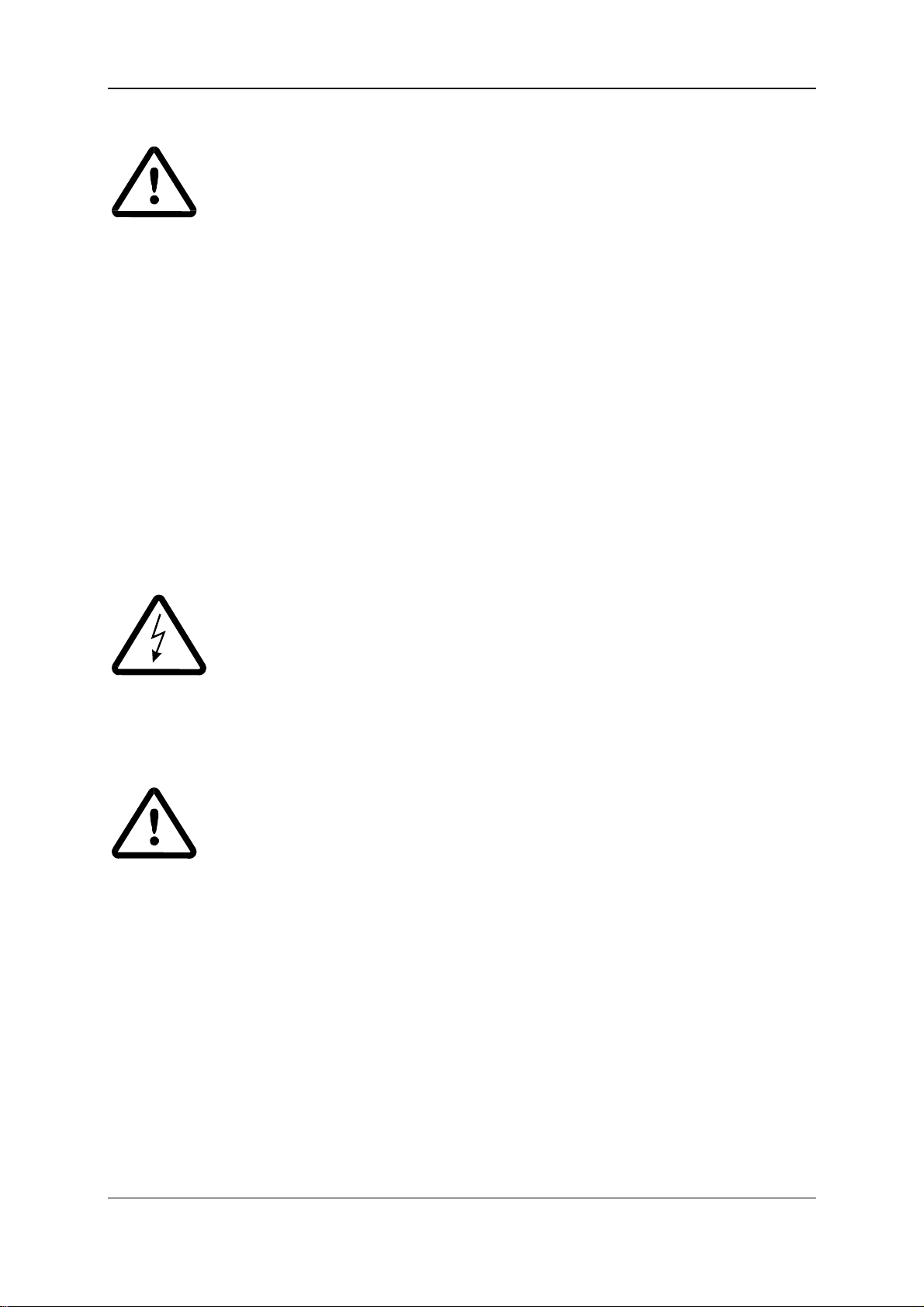
WARNING
When operating electrical equipment, some parts of the equipment always carry dangerous voltages.
Ignoring these safety instructions and warnings may result in serious personal injury and/or damage to
property.
Only qualified personnel who are familiar with the safety information, assembly, operation and maintenance instructions may carry out work on this equipment.
Danger Information
On the one hand, the information below is for your own personal safety and on the other to prevent
damage to the described products or to other connected equipment.
In the context of the operating instructions and the information on the products themselves, the terms
used have the following meanings:
DANGER
This means that death, severe personal injury, or damage to property will occur unless appropriate
safety measures are taken.
WARNING
This means that death, severe personal injury, or considerable damage to property may occur unless
appropriate safety measures are taken.
NOTE
This draws your attention to important information about the product, handling of the product or to a
particular section of the documentation.
2 Basic Feed Unit BUG 3/2/20
5.96064.02 Baumüller Nürnberg GmbH
Page 11
Safety Information
Qualified Personnel
In the context of the safety-specific information in this document or on the products themselves, qualified personnel are considered to be persons who are familiar with setting up, assembling, commissioning and operating the product and who have qualifications appropriate to their activities.
Trained or instructed or authorized to commission, ground and mark circuits and equipment in accordance with recognized safety standards.
Trained or instructed in accordance with recognized safety standards in the care and use of appropriate safety equipment.
Appropriate Use
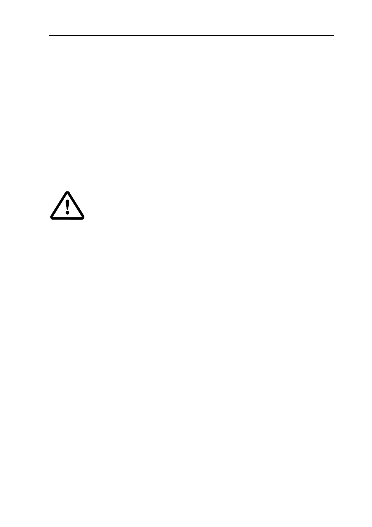
WARNING
You may only use the equipment/system for the purposes specified in the operating instructions and in
conjunction with the third-party equipment and components recommended or authorized by
BAUMÜLLER NÜRNBERG GmbH.
For safety reasons, you must not change or add components on/to the equipment/system.
The machine minder must report immediately any changes that occur which adversely affect the
safety of the equipment/system.
Appropriate use also includes observing the operating instructions and complying with the conditions
of inspection and maintenance.
BUG 3/2/20 Basic Feed Unit 3
Baumüller Nürnberg GmbH 5.96064.02
Page 12

Safety Information
4 BUG 3/2/20 Basic Feed Unit
5.96064.02 Baumüller Nürnberg GmbH
Page 13
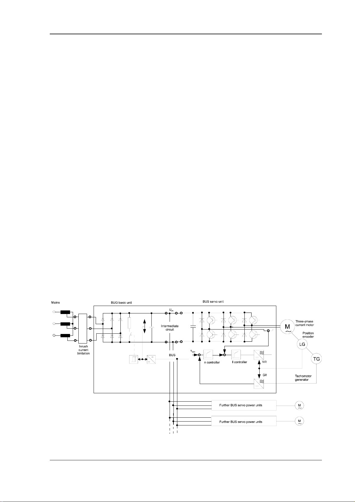
General Technical Data
2 TECHNICAL DATA
2.1 General
The motor and the converter must be matched to one another to be able to fulfil the requirements
made of the drive system three-phase current servo motor and the converter. Our BAUMOTRONIC
converters, which have been specially developed for servo drives, are transistor converters for fourquadrant operation.
The BAUMOTRONIC converter system is of modular structure and comprises the following units:
− the BUG basic feed unit
− the BUS servo power unit
The BUG 2/3/20 named basis feed units are mains-side power converters for feeding the BUS 3/21/20
drive amplifiers. They have a ballast circuit to dissipate the drive´s breaking energy. They are available
with internal ballast resistor or, as E version with a connector for external resistors.
Features:
− BUG 3 basic unit for up to 10.5 kW
− BUG 2 basic unit for up to 18 kW
− BUG 20 basic unit for up to 36 kW
− Connection using a pre-transformer of 400 V/230 V 3 ∼
− Servo power units' current supplied from the intermediate circuit
− Switching power supply with wide voltage range continues to be ready-for-use while the inter-
mediate circuit is charged
− Ballast circuit with high peak power integrated in the basic feed unit
BUG 3/2/20 Basic Feed Unit 5
Baumüller Nürnberg GmbH 5.96064.02
Page 14

Technical Data General
2.1.1 Description of Function
Intermediate Circuit
The intermediate circuit, which supplies the connected servo units, is fed from the mains via an external matching transformer and the uncontrolled bridge rectifier.
Starting Current Limitation Device
If no measures were taken, the intermediate circuit capacitors would lead to inadmissibly high charging current surges when you switch on the mains current. Mains transformers of up to 5 kVA automatically reduce the charging current surge to a non-dangerous level. In the case of large transformers,
you must install a starting current limitation device on the input side.
This device is shunted out after the start-up stage.
Power Supply
The internal switching power supply generates the supply voltages for the connected servo units from
the intermediate circuit or from an external auxiliary voltage.
In addition, permanent monitoring is carried out of the temperature, the intermediate circuit voltage,
the supply voltages and the ballast function. In the case of inadmissible values, the system issues a
message that is further-processed appropriately.
The system indicates these messages to you directly by means of LEDs.
Ballast
When the drive is operating in regenerative mode, it feeds back to the intermediate circuit and raises
its voltage. If this voltage exceeds an impermissibly high value, the integrated ballast transistor
switches the ballast resistor (which can be external if desired) to the intermediate circuit and removes
the excess energy.
6 BUG 3/2/20 Basic Feed Unit
5.96064.02 Baumüller Nürnberg GmbH
Page 15
General Technical Data
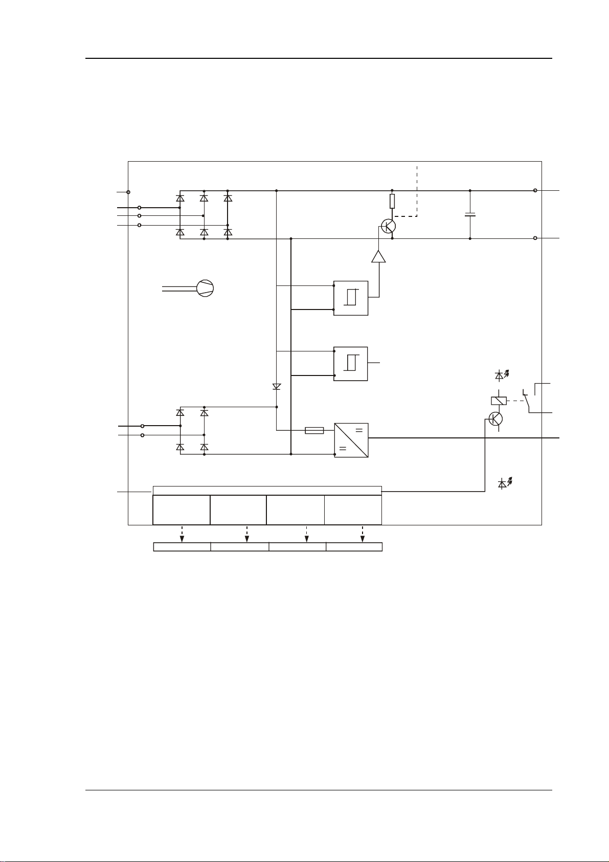
2.1.2 Block Diagram
Block Diagram of BUG Basic Unit
PE
L1
L2
L3
Fan supplied
internally
Additional
feed
Reset
Error memory
Ballas t resist or
overloading TB
Ballast ON for t > 1.5 s
Intermediate voltage,
Uzk, too high
(>400 V)
+/- 15 V controller
supply not OK
(< 12.5 V)
Ballast
resist or
Ballast control
Intermediate circuit
monitoring
Switching
power supply
Temperat ure of
heatsink,
TKK, is too high
External ballast (option)
Uzk > 375 V
Uzk > 40 0 V
+/- 15 V + 24 V (SELV)
X9: Controller supply
and com municatio ns
Intermediate circuit
L-
Ready for use
Green
Ready for use (SELV)
System
Error
Red
L+
Operating
indicator
TB H6 lights up red Uzk H5 lights up red +/- 15 V H4 lights up red TKK H3 lights up red
BUG 3/2/20 Basic Feed Unit 7
Baumüller Nürnberg GmbH 5.96064.02
Page 16
Technical Data Electrical Data
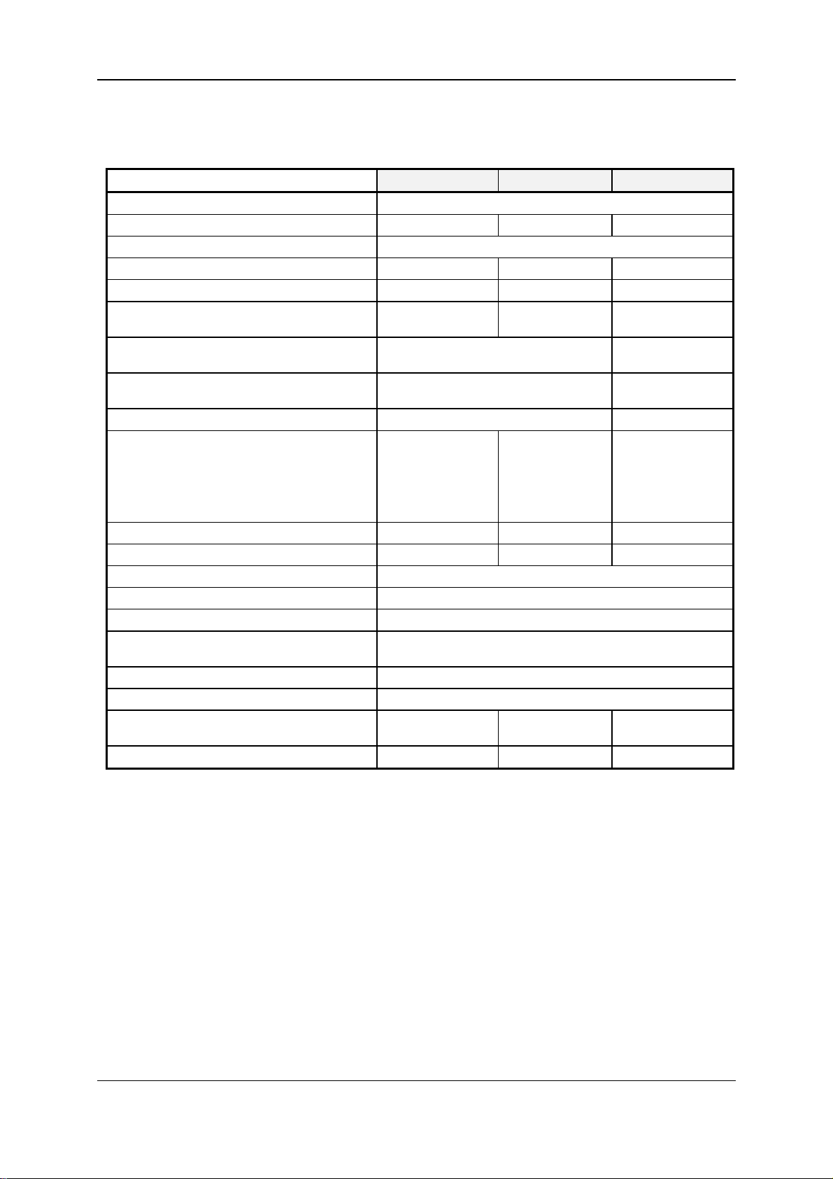
2.2 Electrical Data
Basic Feed Unit BUG 3 - 35 - 30 BUG 2 - 60 - 30 BUG 20 - 120 - 30
Connection voltage
Intermediate circuit power 10.5 kW 18 kW 36 kW
Intermediate circuit rated voltage 310 V
Rated current at TK = 45° C and TB = 45° C 35 A 60 A 120 A
Peak current for t ≤ 1 s 105 A 180 A 360 A
Peak starting current ION,
Max. allowed for t ≤ 10 ms
Controller supply
Additional feed via transformer 230 V/160 VA
Isolation transformer T2 1900 7153 1900 7176
Ballast resistor R
peak power for t < 1.5 s
peak power for t < 1.8 s
internal (version B)
external (version E)
rated power
Power loss in rated operation without ballast
Fan No Supplied internally Supplied internally
Environmental operating temp. range T
Coolant temperature range T
Power reduction 3 %/°C
Max. site altitude at rated loading
(see also char. curve 1 on page 9)
Relative humidity 15 % - 85 % no condensation
Storage temperature range -30 °C ... +70 °C
Dimensions 100 x 250 x 230
Weight 3 kg 9 kg 12 kg
1)
2)
4)
3 x 230 VAC +10 %/-15 % 50/60 Hz
300 A 700 A 1400 A
±15 V/100 W
+24 V/10 mA
±15 V/200 W
+24 V/10 mA
230 V/250 VA
potential-free
B
9 kW
16 Ω/190 W
≥ 16 Ω
As required
5)
6) 7)
B
6) 7)
K
110 W 200 W 280 W
0 ... 45 °C (with power reduction, 55 °C)
0 ... 45 °C (with power reduction, 55 °C)
15 kW
9.4 Ω/400 W
≥ 8 Ω
As required
potential-free
37 kW
4 Ω/900 W
≥ 4 Ω
As required
1000 m above sea level
105 x 400 x 330mm157.5 x 400 x 330
mm
mm
8 BUG 3/2/20 Basic Feed Unit
5.96064.02 Baumüller Nürnberg GmbH
Page 17
Electrical Data Technical Data
Remarks on the Technical Data
1) Connection voltage of the basic unit = secondary voltage U
of transformer T1.
2
Rated value: 230 V; never directly connect devices to the mains.
2) Max. permissible non-repetitive peak current (t < 10 ms) at switch-on; this is limited by the inductivity of transformer T
on the input side and possible additional current limiting resistors, R2 (refer
1
to the transformer layout); switch-on frequency: once per half hour.
3) Controller supply (switching power supply); the total of all the triggering power of all the BUS devices may not exceed the power of the selected BUG unit's switching power supply!
4) Additional feed for the mains unit; useful when carrying out trouble-shooting with a test adapter
BU; the isolating transformer (T
) is specially matched to the mains unit; transformer T2 is not
2
needed for operating the basic units.
5) Power losses of the devices; on one hand, this is important for rating the switching cabinet, and
on the other for rating the BUG basic unit:
Σ P
+ Σ P
V
≤ PN (BUG) (see also Transformer Rating)
tomotor
6) Coolant temperature measured 50 mm below the device according to DIN VDE 0160/DIN VDE
0558 Part 1; in rated operation, T
as well as TB must be below the specified limit temperatures.
K
Otherwise, you must reduce the device's rated current.
7) Operating environment temperatures measured 300 mm away from the unit at the most, halfway
up the device according to DIN VDE 0160/DIN VDE 0558 Part 1; T
and TK must not exceed the
B
specified limit temperature. The same conditions apply as before.
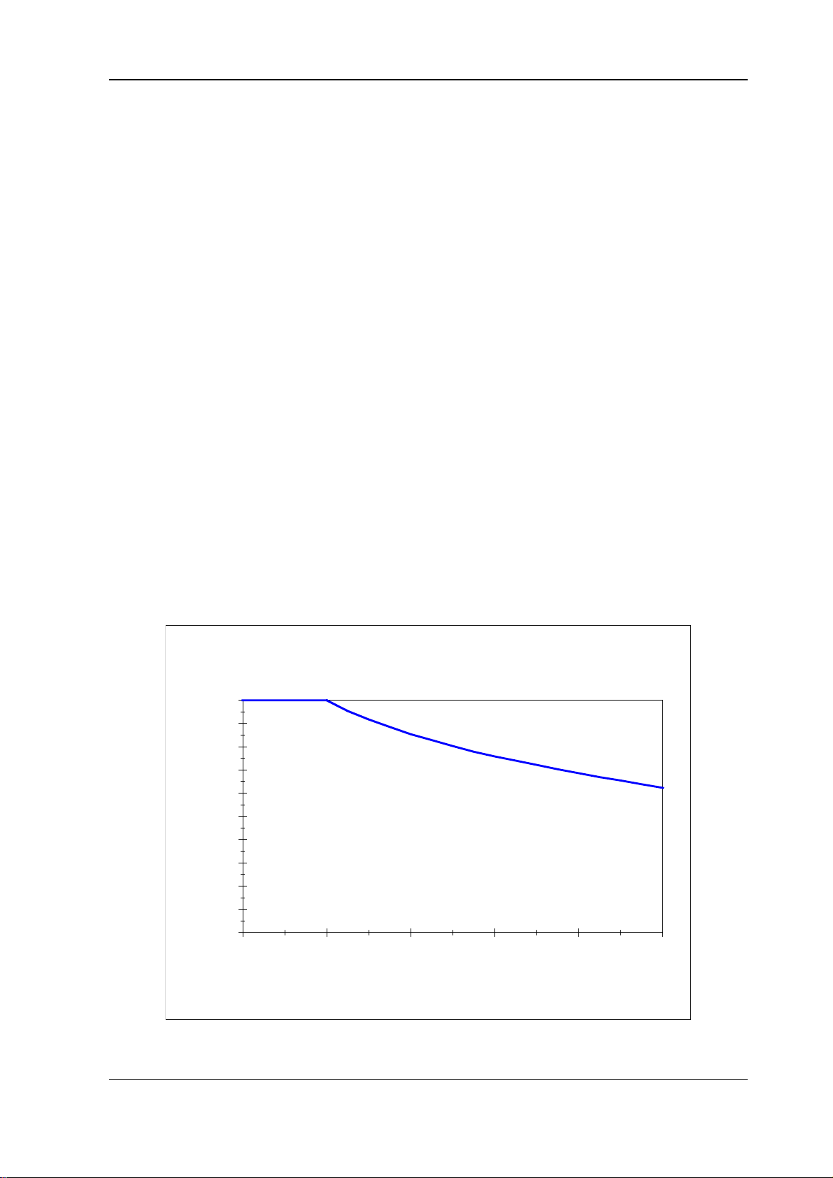
Characteristic curve 1: Load in dependence on the site elevation
Load in dependence on
installation height
100
90
80
70
60
50
40
Load [%]
30
20
10
0
0 1000 2000 3000 4000 5000
Installation height [m]
BUG 3/2/20 Basic Feed Unit 9
Baumüller Nürnberg GmbH 5.96064.02
Page 18
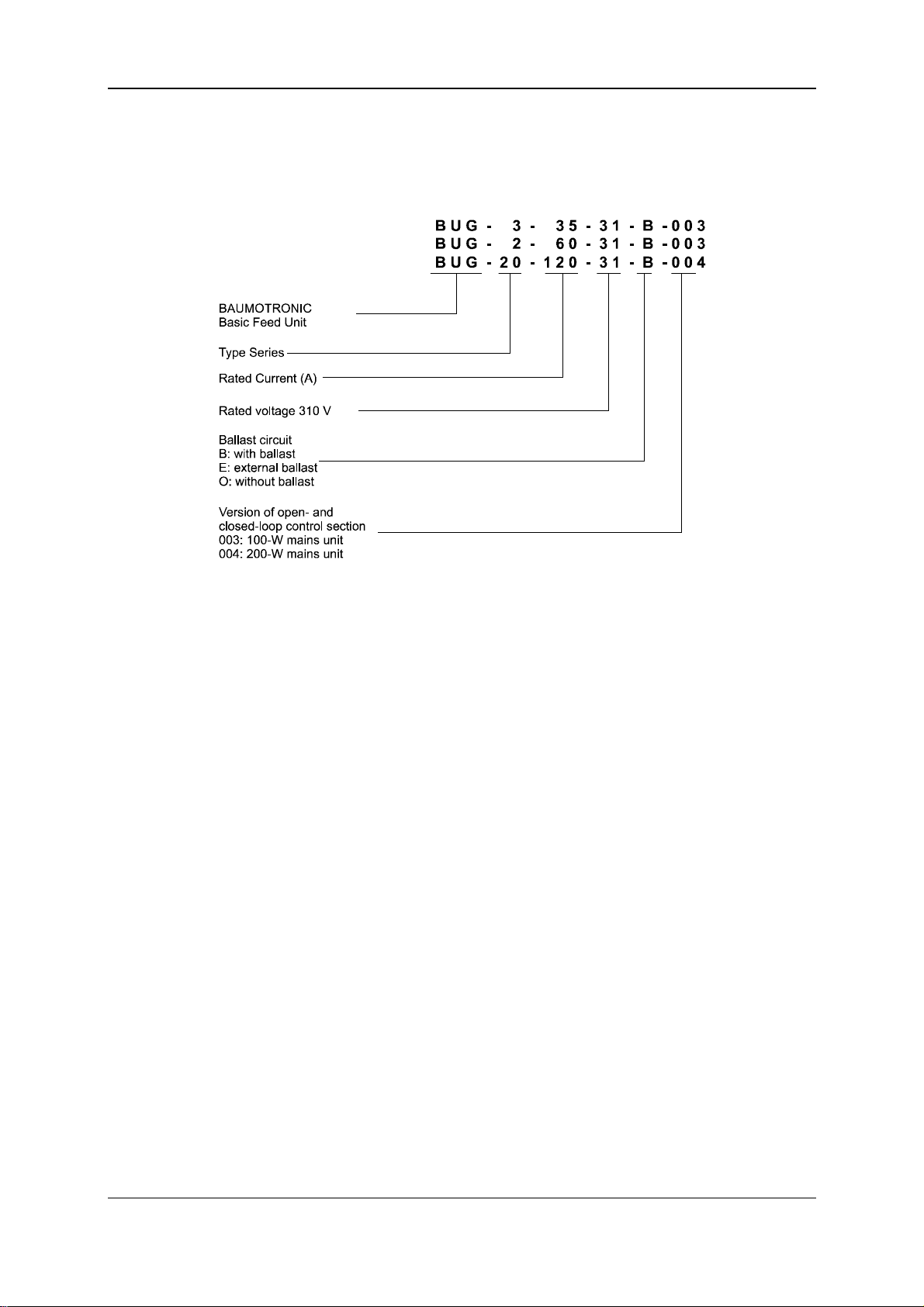
Technical Data Type Code
2.3 Type Code
10 BUG 3/2/20 Basic Feed Unit
5.96064.02 Baumüller Nürnberg GmbH
Page 19
Transportation, Unpacking
3 TRANSPORTATION, UNPACKING
The units are packed at the factory in accordance with the order.
You should avoid jarring packages in transit or jolting them, e.g. when setting them down on the
ground.
After unpacking the package(s) and checking that the shipment is complete, you can start assembly.
Cardboard, cartridge paper and/or wood are used as packaging materials that can be disposed of
according to local regulations.
Report any damage in transit without delay.
DANGER
If the unit has been damaged in transit, do not connect it to the mains until appropriate high-voltage
testing has been carried out.
Ignoring this information can result in death, severe personal injury, or considerable damage to property.
Environmental conditions must be regulated according to pr EN 50178.
BUG 3/2/20 Basic Feed Unit 11
Baumüller Nürnberg GmbH 5.96064.02
Page 20

Transport, Unpacking
12 BUG 3/2/20 Basic Feed Unit
5.96064.02 Baumüller Nürnberg GmbH
Page 21
Assembly
4 ASSEMBLY
WARNING
The owner is responsible for assembly of the described unit, motor, transformer as well as any other
equipment in accordance with safety regulations, such as DIN or VDE; equally, you must ensure that
all other relevant national and local regulations are met with regard to cable ratings and protection,
grounding, disconnectors, overcurrent protection, etc.
Protect drive converters from impermissible loading. In particular, components may not be warped
and/or insulation gaps changed during transportation and handling. Avoid touching electronic components and contacts.
Ensure that there is no blockage of cooling air flowing into and out of the equipment and that there is
enough space above and below the equipment to prevent overheating.
The units are protected from direct contact by being installed in commercially available switching cabinets that meet the minimum protection requirements of preliminary standard EN 50178/VDE
0160/11.94, Section 5.2.4.
Plastic protectors on the devices that cover up the connections act as additional guards preventing
accidental contact at commissioning and in the case of casual use of control elements located close to
the equipment (DIN VDE 0106 Part 100, Accident Prevention Regulation VBG4 "Electrical Systems
and Equipment").
Drive converters contain components at risk from electrostatic energy which can be damaged by incorrect handling.
Electrical components must not be mechanically damaged or destroyed as this could lead to health risks!
WARNING
Lifting incorrectly can result in personal injury or damage to property. The device should only be lifted
by appropriately qualified personnel using the proper equipment.
BUG 3/2/20 Basic Feed Unit 13
Baumüller Nürnberg GmbH 5.96064.02
Page 22
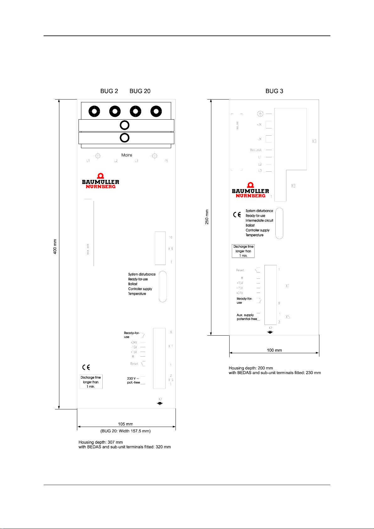
Assembly Dimensions
4.1 Dimensions
14 BUG 3/2/20 Basic Feed Unit
5.96064.02 Baumüller Nürnberg GmbH
Page 23
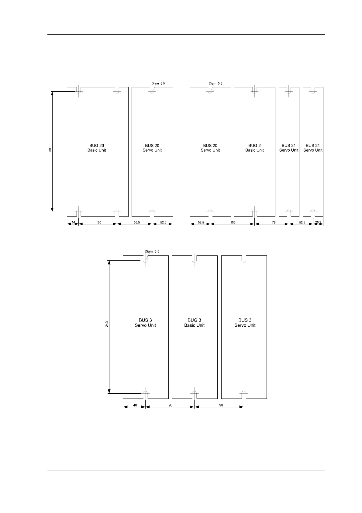
Dimensions Assembly
Fastening Holes
BUG 3/2/20 Basic Feed Unit 15
Baumüller Nürnberg GmbH 5.96064.02
Page 24
Assembly Assembly Information
4.2 Assembly Information
WARNING
Lifting incorrectly can result in personal injury or damage to property. The device should only be lifted
by appropriately qualified personnel using the proper equipment.
• Install the units vertically in a switching cabinet. Mount the BUS 3/21/20 servo power units next to
the BUG 3/2/20 basic feed unit and connect the intermediate circuit using the supplied rails.
DANGER
Relatively long connections are not allowed, since there is a risk of destroying the device!
WARNING
It is crucial to comply with the ventilation measures listed below. Ignoring these measures can lead to
the device overheating.
• Ventilation must be in the specified direction from the bottom to the top.
• Ensure that the flow of air is unobstructed.
• There must be a minimum clearance above and below the device of
100 mm
and you must ensure that there is enough cooling air that can circulate freely!
• The temperature of the coolant 50 mm below the devices may be up to 45 °C.
• Do not locate any additional sources of heat above or below the devices.
• You must avoid degrees of contamination 3 and 4 according to provisional standard
EN 50178:1994 Section
(VDE 0558 Part 1a, Sections 5.4.3.2.1 and 5.4.3.2.2).
5.2.15.2. The devices are suitable for use in enclosed workshops.
• The live parts take more than one minute to discharge.
16 BUG 3/2/20 Basic Feed Unit
5.96064.02 Baumüller Nürnberg GmbH
Page 25
Danger Information Installation
5 INSTALLATION
5.1 Danger Information
WARNING
This equipment carries a dangerously high voltage and has dangerous rotating parts (fans). Ignoring
the safety and warning information may result in death, severe personal injury or damage to property.
The machine operator is responsible for mounting the mono power unit, the motor, the transformer
and any other equipment in accordance with appropriate safety regulations (e.g. DIN, VDE); equally,
you must ensure that all other relevant national and local regulations are met with regard to cable ratings and protection, grounding, disconnectors, overcurrent protection, etc.
If you carry out works at power-on drive converters you must obey the national safety rules to avoid
accidents. The electrical installation must be carried out according to the resoective guidelines (e.g.
cross-sections, fuses, protective earth attachment).
The protective earth connection has to be carried out according to DIN EN 60204/VDE 0113
Part1/06.93; section 8.2.2, also pr EN 50178/VDE 0160/11.94, sections 5.3.2 and 8.3.4, or the respective local guidelines. Information about EMC-correct installation – as screeening, earthing, positioning of filters and running cables, you will find in this document. This information must be respected
also when using CE-marked drive converters.
The responsibility for keeping the limits requested by the EMC laws has the manufacturer of the plant
or machine.
Relatively high leakage to ground occurs in the converter and the motor, i.e. the drive may be incompatible with current-operated e.l.c.b.s (corresponding to provisional standard EN 50178:1994 Section
5.2.11.2).
You must only use variable-speed drives in applications that correspond to valid EN specifications.
DANGER
The intermediate circuit carries a voltage!
Be particularly careful before touching the drive shaft directly or indirectly with your hands. This is only
allowed when the system is deenergized and the drive is stationary.
Safety devices must never be deactivated.
BUG 3/2/20 Basic Feed Unit 17
Baumüller Nürnberg GmbH 5.96064.02
Page 26
Installation EMC Information
5.2 EMC Information
General Information about Converters
Modern semiconductor technologies such as MCTs and IGBTs are intended to minimize the power
loss in the converter by switching more quickly and, with this, to continually reduce the size of the
power section. As a result, when running converters you must meet specific conditions to avoid electromagnetic influences caused by switching operations.
Disturbances can occur due to:
• capacitive fault currents caused by high rates of voltage rise when bipolar transistors and IGBTs
switch.
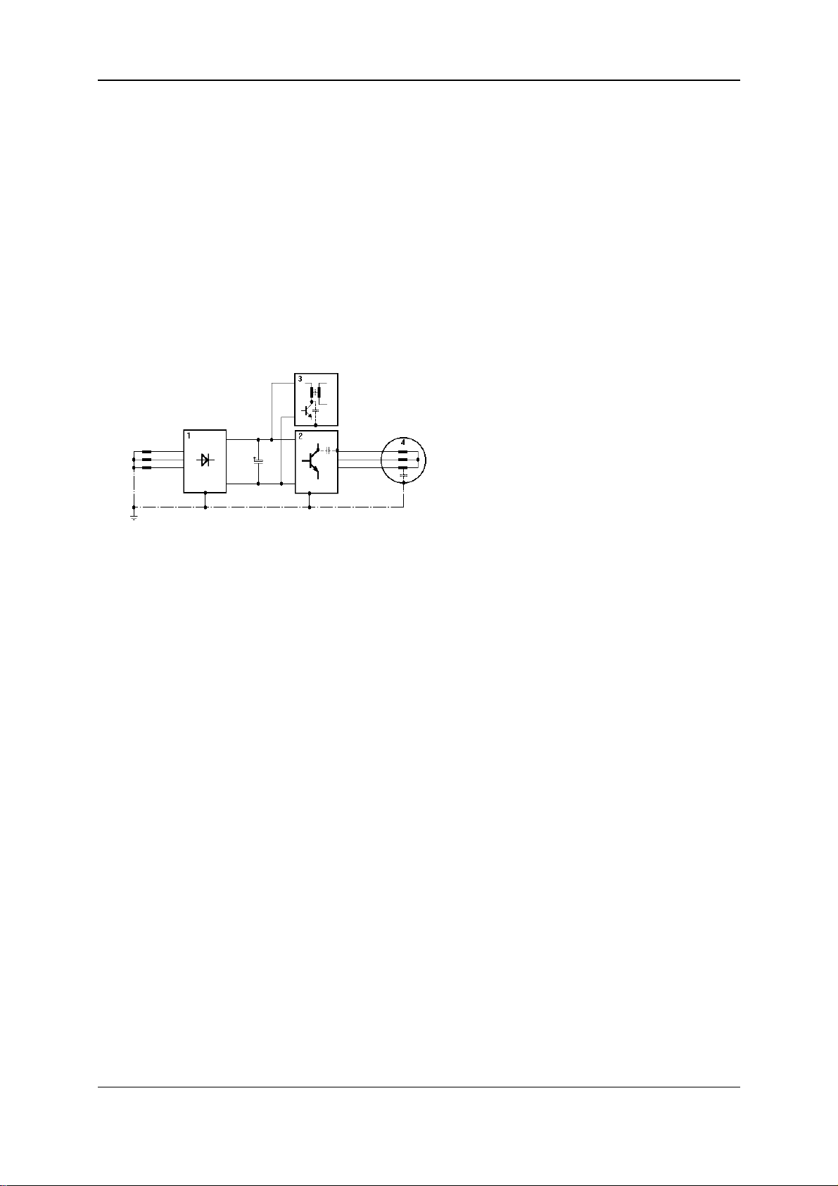
1 Feed
2 Power section
3 Switching power supply
4 Motor
• high currents and high rates of current rise in the motor lines. The disturbance energy bound in mag-
netic fields reaches frequencies of between a few Hertz and about 30 MHz. Due to the high rates of
current rise, additional electromagnetic fields occur with frequencies of up to approximately 600 MHz.
• high clock rates and fast logic circuits (electromagnetic field/16 MHz...1 GHz).
• system perturbation and harmonics caused by commutations and non-sinusoidal network loading,
in particular with line-commutated converters (100 Hz ... 20 kHz).
German EMC Law (EMVG)
This converter complies with Paragraph 5, Section 5, Sentence 3 of the German EMC Law (EMVG)
dated 09.11.92.
"Devices that are exclusively manufactured or stocked as vendor parts or spare parts for further processing
by industrial companies or craftsmen or by other specialists in the field of electromagnetic compatibility do
not need to comply with the protective requirements of Paragraph 4,
formity certification and marking, assuming that the devices in question cannot be run automatically."
Section 1, nor do they need EU con-
This does justice to the fact that EMC is heavily dependent on the individual subassemblies and components in the switching cabinet. With regard to the total costs of the machine, it is preferable to troubleshoot an entire system rather than each of its individual components.
18 BUG 3/2/20 Basic Feed Unit
5.96064.02 Baumüller Nürnberg GmbH
Page 27
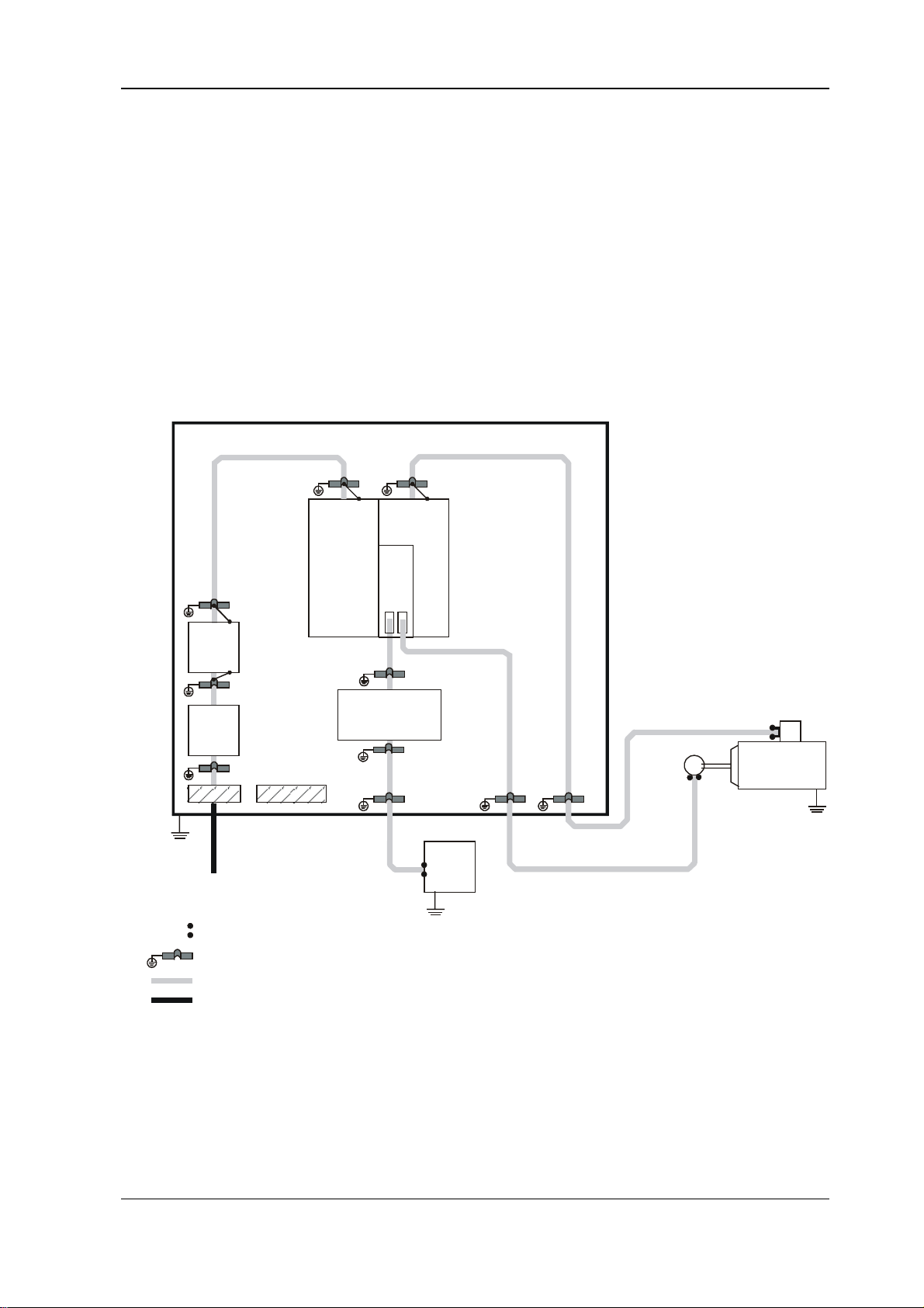
EMC Information Installation
The information on the next pages is intended to allow you to configure your system on the basis of
the latest knowledge in the field of EMC and to comply with legal regulations.
Measures for Ensuring EMC
To ensure EMC, you must observe the configuration information below.
Cabling
• To suppress radiated noise outside the converter, you should screen all the connected cabling.
Also observe the topics in the section entitled "Screening".
Switching cabinet with bare mounting plate
Feed
Unit
Mains
Filter
Tra ns-
former
Lines routed via metallic conduit threads or connector housing with connected screen
Screen's point of contact with mounting plate
Screened Line
Unscreened Line
Servo
Power Unit
Closed-Loop
Open-Loop
Controller
Controller
Operator Panel
Distance of at least 20 cm
G
BUG 3/2/20 Basic Feed Unit 19
Baumüller Nürnberg GmbH 5.96064.02
Page 28
Installation EMC Information
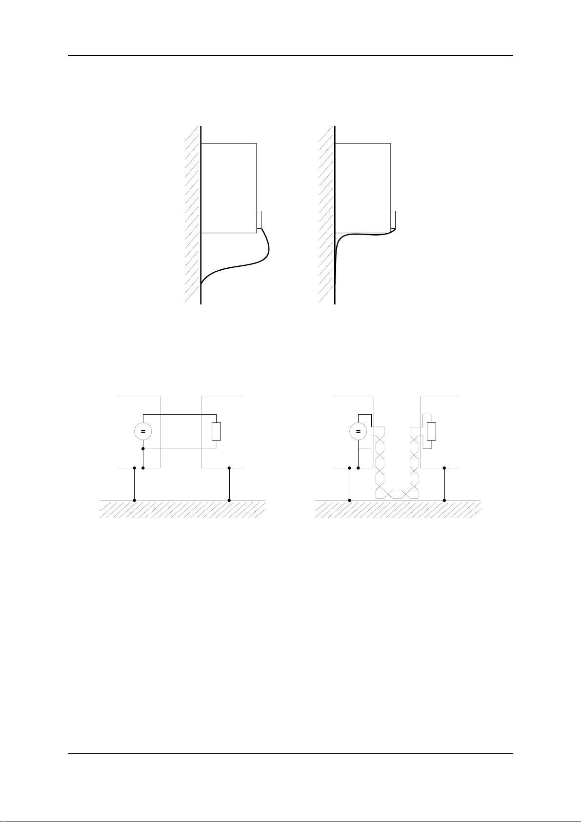
• You achieve the lowest possible effective antenna height by routing the cable directly on the
ground of the metallic rack.
Wrong Right
• You should route all lines as close as possible to the conductors of the ground system to reduce
the effective loop area for magnetic coupling.
Wrong Right
• When parallel-routing signal and control lines across power cables, the conductors must be at least
20 cm apart.
• Lines of different EMC categories should only cross at an angle of 90°.
• In the case of symmetrical signal transfer (e.g. differential amplifier inputs for the speed specified
value), twist the conductors of each pair of wires together and twist the pairs of wires together.
• The converter to ground plate earth-connection should be as short as possible (less than 30 cm).
Use large cross-sections (more than 10 mm²).
• Sources of interference such as fuses, transformers and chokes and modules that are sensitive to
interference like µPs, bus systems, etc. should be located at least 20 cm away from the converter
and its cabling.
20 BUG 3/2/20 Basic Feed Unit
5.96064.02 Baumüller Nürnberg GmbH
Page 29
EMC Information Installation
• Avoid reserve loops on overlong cables.
• You must ground reserve lines at both ends (this has an additional screening effect, avoids ca-
pacitively coupled, dangerous touch voltages).
Grounding
• From an EMC point of view, classical star grounding is no longer adequate for reducing the influ-
ence of disturbances at relatively high frequencies that occur as a result of converter operation.
Better results can be achieved by a reference surface that must be linked to the devices' frame
grounds over a wide area (e.g. a bare, metallic mounting plate and parts of the housing).
If it is not possible to use a broad reference place, it is sensible to mount the main equipotential
busbar directly next to the converter, since this device generates the greatest potential jumps,
compared with the other components in the switching cabinet, due to the steep switching edges
(the ground connection should be less than 30 cm long if possible).
• Route all earth conductors and screens as closely as possible above the frame ground to prevent earth
circuits.
• If it is possible to earth the controller reference voltage, make this connection with cabling that has
as large a cross-section as possible and is less than 30 cm long.
• Remove insulating layers, such as varnish, adhesives, etc., from the frame ground connections. If nec-
essary, use DIN 6798 serrated lock washers or similar to ensure a permanent, conductive contact. To
prevent corrosion of frame ground connections, use suitable pairs of metals (electrochemical displacement series), and keep conductive electrolytes away from the connection by means of a protective
coating (e.g. grease).
• Always connect screens at both ends to the frame ground; the connection should be over a wide
area and conductive. This is the only way to suppress the effects of magnetic or high-frequency
noise interference fields. If there are problems with earth circuits (e.g. double earth fault of the
specified value conductor screen), the receive side should be galvanically connected and the
transmit side capacitively connected.
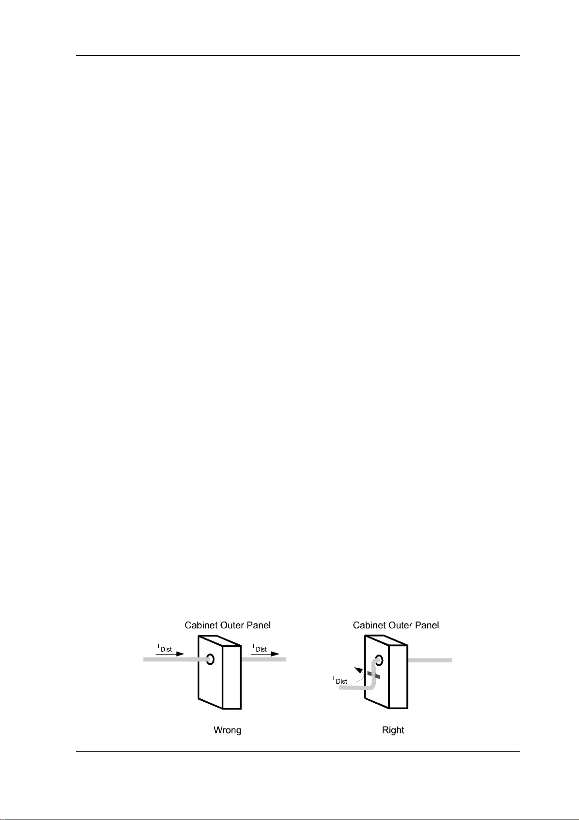
• When routing cable screens through panels that separate different EMC areas, the cables must be
in contact with the panel.
Cables that are routed through the outer panels of screening housings without special measures
(e.g. filtering), can have an adverse effect on the screening capability of the housing. For this reason, you must make a conductive connection of the cable screens to the screening outer panel at
the point at which the cable enters the housing.
The distance of the last screen contact point to the exit from the cabinet must be as short as possible.
BUG 3/2/20 Basic Feed Unit 21
Baumüller Nürnberg GmbH 5.96064.02
Page 30
Installation EMC Information
Screening
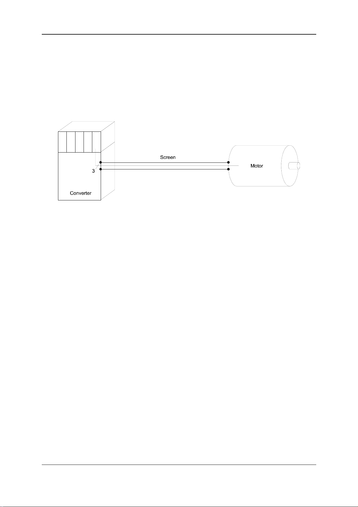
• The screen is effective against magnetic fields if it is connected to frame ground at both ends.
With electrical fields, the screen is effective when it is connected to frame ground at one end.
However, in the case of (electrical or magnetic) fields with high frequencies (depending on the
length of the line), you must always connect the screen at both ends due to the linkage (electromagnetic field).
Connecting the screen to frame ground at both ends ensures that the conductor does not leave the
screening "system housing".
• Frame-grounding of conductor screens on both sides does not entirely rule out the influence of
earth circuits (potential differences on the frame ground system). However, this is very rare if you
carry out the measures described in the previous sections entitled "Cabling" and "Grounding".
You can also make a capacitive RF connection of a screen to frame ground. This prevents lowfrequency interference due to earth circuits.
Screened cables that pass through different EMC areas must not be separated at terminals, since
screen damping would otherwise be considerably reduced. The cables should be routed to the next
module without interruption.
• Make the screen connection low-impedance and over a wide surface area. Cable tails that are only
three centimetres long (1 cm of wire = 10 nH) reduce the screening effect in the megahertz range
by up to 30 dB!
NOTE
The braided screen must have a coverage of at least 85%.
The following lines have particularly high levels of interference potential:
− the motor line
− the line to the external ballast resistors
− the line between the mains filter and the converter
22 BUG 3/2/20 Basic Feed Unit
5.96064.02 Baumüller Nürnberg GmbH
Page 31
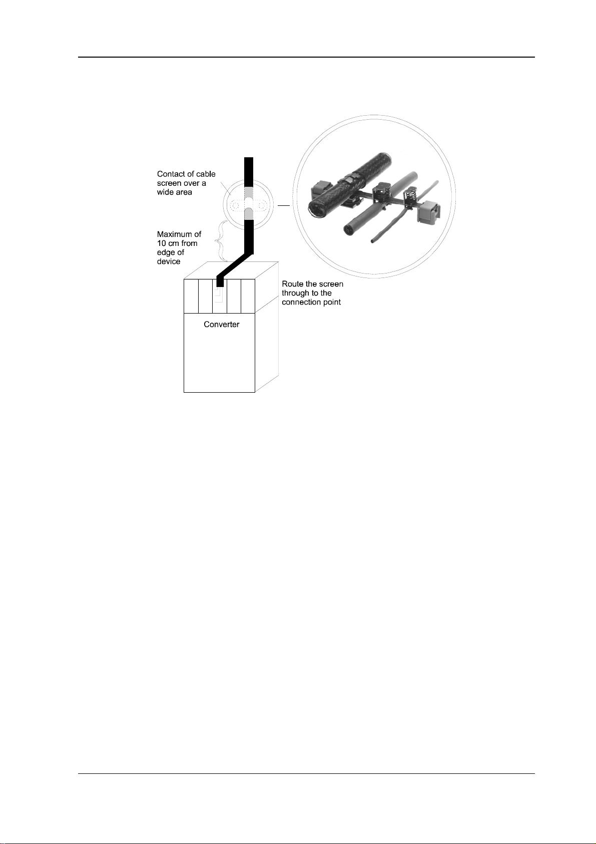
EMC Information Installation
• Suggestion for screen connection:
Filtering
No filters are needed for the converter to function. However, under some circumstances, filters may be
needed on the input or the output side to comply with EMC regulations.
If you have any queries about filter design, please ask for the description entitled “Baumüller Filters for
Network Applications, BFN”.
Filter Assembly
• Mount the filter directly next to the converter. With lines that are more than 30 cm long, you must
screen the mains line between the converter and the filter (frame-ground on both sides).
• Physically separate the filter's input and output lines by more than 30 cm.
• Make a broad connection between the filter housing and frame ground.
Discharge Currents
Due to the principle of operation, parasitic capacities in the filter, the mains unit, the motor cable and
the motor winding cause discharge currents of around 100 mA and higher.
This means that converters with earth leakage circuit-breakers may be incompatible!
In this context, you should observe the safety information in provisional standard EN 50178:1994 Section
5.2.11.2.
BUG 3/2/20 Basic Feed Unit 23
Baumüller Nürnberg GmbH 5.96064.02
Page 32
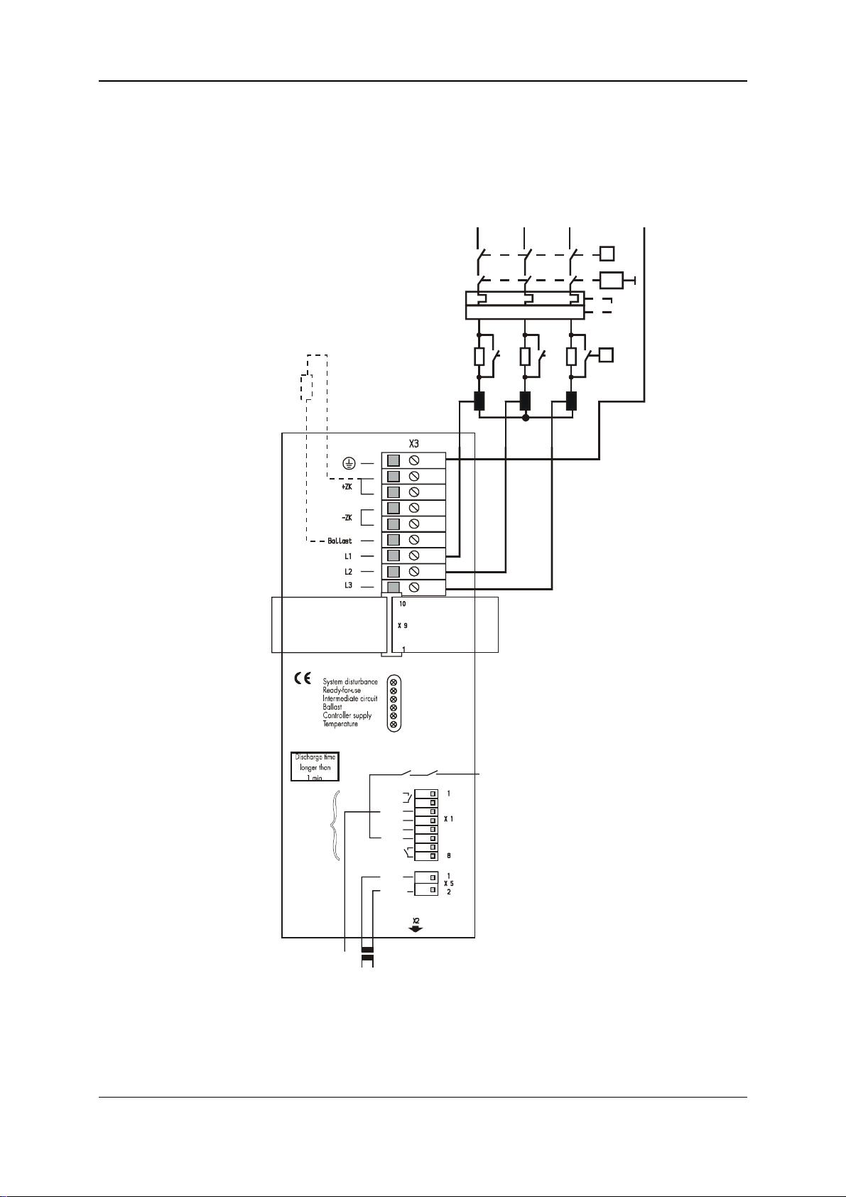
Installation Connection Diagram
5.3 Connection Diagram
5.3.1 BUG 3
L1 L2 L3 PE
K1
F1
Option E
External ballast resistor or BUR
Ba+
R
B
Ba-
I>
T1
L1
I> I>
L2 L3
K2
R2
PE
Intermediate circuit
L+ (ZK+)
Intermediate circuit
(ZK-)
L-
To further
servo units
SELV
Controller enable (SELV)
K1
1
Reset
2
M
3
+15 V
4
5
-15 V
6
+24 V
7
Ready
8
230 V
1
2
pot.-free
To further
servo units
(SELV)
230-V additional feed
To NC ground
T2
potential-free!
24 BUG 3/2/20 Basic Feed Unit
5.96064.02 Baumüller Nürnberg GmbH
Page 33
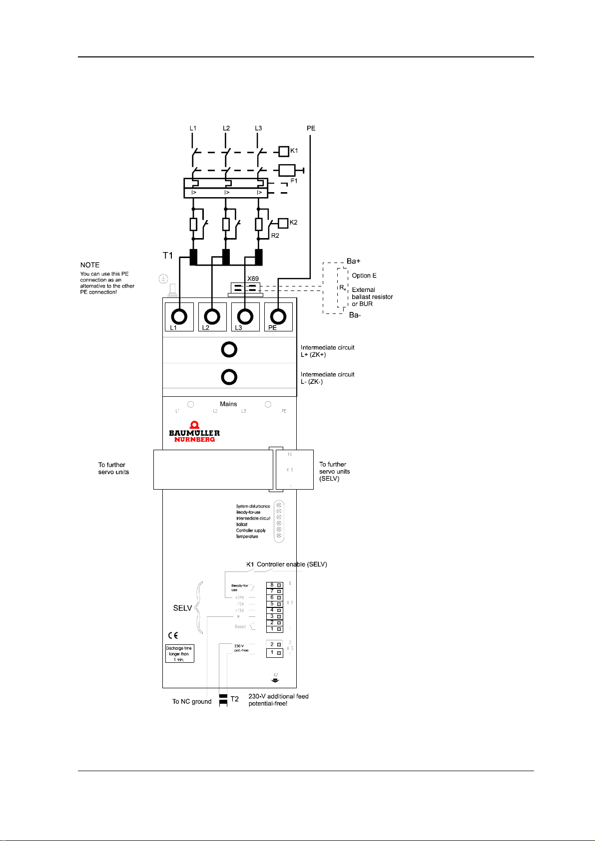
Connection Diagram Installation
5.3.2 BUG 2
BUG 3/2/20 Basic Feed Unit 25
Baumüller Nürnberg GmbH 5.96064.02
Page 34
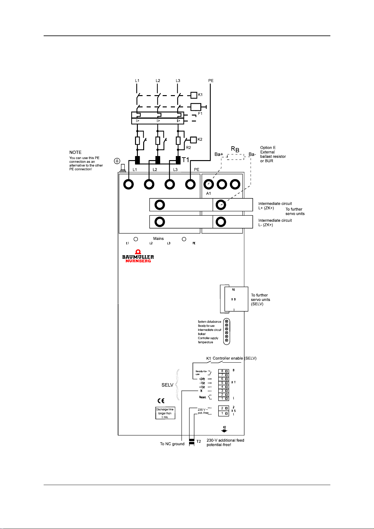
Installation Connection Diagram
5.3.3 BUG 20
26 BUG 3/2/20 Basic Feed Unit
5.96064.02 Baumüller Nürnberg GmbH
Page 35
Connection Diagram Installation
5.3.4 Connection Information
F1 Line protection in accordance with VDE 0100, slow-blowing fuse of 2-3 times
the transformer's rated current or motor protection switch in systems with only
one axis.
Current-operated e.l.c.b.
T1 Autotransformer YNO or isolating transformer Yny0; inrush current limitation
T2 Isolating transformer for additional feed of the auxiliary controller supply
K1 Mains contactor with auxiliary contact for controller enable
K2, R2 Starting current limitation prevents the B6 rectifier's permissible non-repetitive
The principles on which the power converter and the motor work lead to relatively high leakage currents to earth, i.e. the drive may be incompatible with
current-operated e.l.c.b. systems. For configuration, take into account provisional
standard EN 50178:1994 Section 5.2.11.
device depending on the type and power of the transformer. For further details,
refer to Transformer Accessories
BUG 2 and 3: isolating transformer 230/230, 160 VA, No. 1900 7153
BUG 20: isolating transformer 230/230, 250 VA, No. 1900 7176
With this option, error messages are retained even if K1 has dropped. The option is not necessary for operation. Use one transformer per basic unit.
peak current, I
R = 10 Ω/50 W after one second; this is always necessary when using capacitor unit BUK, otherwise only with transformers T
available as a complete module designated WSV (chapter 5.4.2)
, from being exceeded; the contactor shunts out resistors
ON
rated at 5 kVA and above;
1
L+, L-
ZK+, ZK-
Intermediate circuit connection to the BUS units via the supplied busbars.
With several servo units, arrange the BUG in the middle.
Wire the BUG 3 with 4 mm² wires.
DANGER
When using autotransformers, the intermediate circuit carries mains potential;
When using isolating transformers, ground L- (ZK-).
L1, L2, L3, PE Cross-section according to EN 60204-1:1992
For line-laying, refer to EMC Information
R
B
Drives that have a very high centrifugal mass or acceleration/braking drives are
run with external ballast. For more information, refer to the section entitled BUR
Resistor Unit.
BUG 3: Connection of an external ballast resistor rated at 10 Ω or above be-
tween ballast and L+.
BUG 2: Connection of an external ballast resistor rated at 8 Ω or above on
connector X69 on the top of the device.
BUG 20: Connection of an external ballast resistor rated at 4 Ω or above be-
tween A1 and ZK+.
BUG 3/2/20 Basic Feed Unit 27
Baumüller Nürnberg GmbH 5.96064.02
Page 36
Installation Pin Assignments
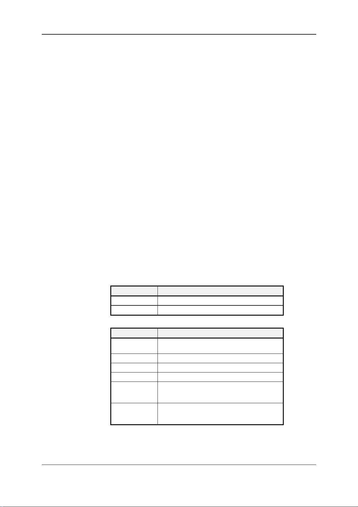
5.4 Pin Assignments
5.4.1 Power Terminals
L1, L2, L3, PE Mains connection (via mains transformer), ground connection
L+ (ZK+)
L- (ZK-) Intermediate circuit connection to the servo power units via the supplied bus-
bars.
Arrange the BUG in the middle of the servo power units.
Wire the intermediate circuit from the BUG 3 and the servo power units with
4 mm² wires.
DANGER
When using autotransformers, the intermediate circuit carries mains potential; when using isolating transformers, ground L-.
X69 Connection of external ballast (BUG 2 only)
A1, L+ (ZK+) Connection of external ballast (BUG 20 only)
L+ (ZK+), Ballast Connection of external ballast (BUG 3 only)
5.4.2 Control Terminals
Plug-in connection X9 Bus connection to the servo power units.
Supply voltages and operating messages are routed via this connection.
Terminal strip X5
Pin No. Assignment
1 Additional feed via isolating transformer T2 230 V
2 Additional feed via isolating transformer T2 230 V
Terminal strip X1
Pin No. Assignment
1
2
3 Device ground
4 +15 V output
5 -15 V output
6 +24 V output
7
8
When both contacts close, the system resets stored
messages whose causes are no longer pending
for controller enables, direction reversal and NP switch
only
Relay contact (max. of 24 V/1 A) closed on ready-foruse is pending for 1-2 seconds after mains contactor
closes K1 (SELV)
AC
AC
Terminal strip X2 Connection for test adapter BU (option)
28 BUG 3/2/20 Basic Feed Unit
5.96064.02 Baumüller Nürnberg GmbH
Page 37
Accessories Installation
5.5 Accessories
5.5.1 Transformers
You connect servo drives to the mains by using a three-phase current transformer. Calculate
the power from the absorbed power, P
the servo units. When rating the transformer, you must take into account a form factor of 1.2
due to the harmonics.
PPP P
+++
MM M M
123 4
P
P
=
M
=+05
.*
G
Mn
*
NN
9550
* η
, of the individual motors added to the power losses of
M
MN: Rated torque in Nm
n
: Rated speed in RPM
N
P: Power in kW
η: Efficiency of motor
P
: Losses of the servo power unit
Bus
G = 1 (for 1 axis)
G = 1.15 (for 2 axes)
P
Bus
G = 1.32 (for 3 axes)
G = 1.75 (for 4 axes)
P
represents an average mean value (
M
When operating at rated speed (
n
n
n
max
n
= 1), you must take into account the complete motor
max
.= 05) matched to a typical CNC feed drive.
power.
Isolating transformer or autotransformer
Autotransformers are preferable at power ratings above 5 kVA. Note that the intermediate
circuit may not be grounded and that potential is connected to the intermediate circuit as well
as the motor. If necessary, you may need to limit the peak starting current. These recommendations apply to Baumüller transformers only!
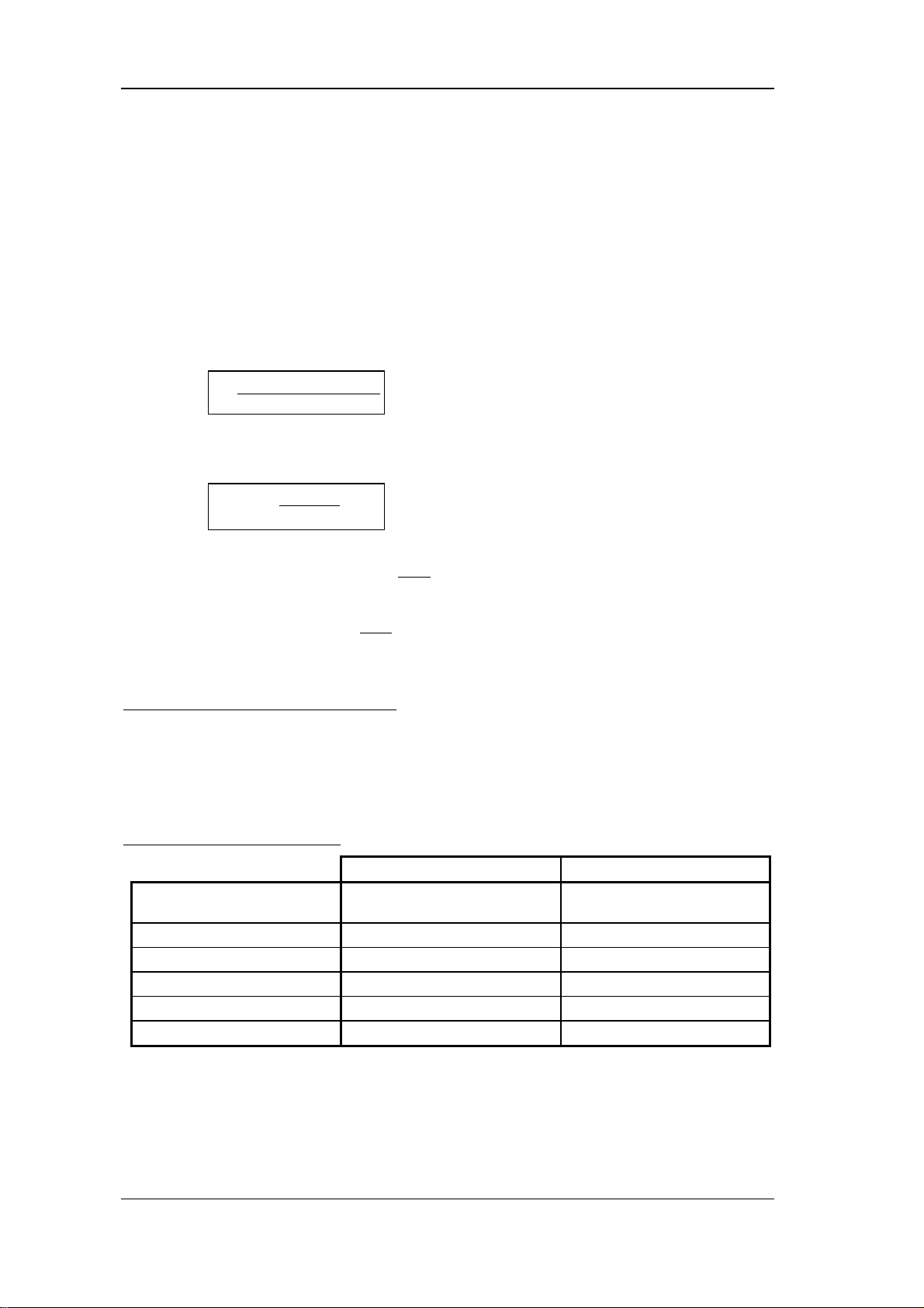
Technical Data of Transformers
Isolating transformer
Rated Input Voltage
Rated Output Voltage 230 V/3 ~ 230 V/3 ~
Switching Group YNy0 Yn0
Mode S1 at 40° C S1 at 40° C
Type of Protection IP 00, Insulation class E IP 00, Insulation class E
Ambient Temperature +40° C max. +40° C max.
400 V/3 ~
50/60 Hz
*)
Autotransformer
400 V/3 ~
50/60 Hz
*)
BUG 3/2/20 Basic Feed Unit 29
Baumüller Nürnberg GmbH 5.96064.02
Do not connect the star point to the mains
Page 38
Installation Accessories
Isolating transformers Autotransformers
P
M
(kVA)
Works
No.
1900 ...
U
(%)
Weight
K
(kg)
Starting current
limitation de-
1)
vice
B
B
U
U
G
G
2
20
P
(kVA)
Works
M
No.
1900 ...
B
U
G
3
0.4 ... 7154 4 7.5 0 0 0 0.4 ... 7159 2 4.2 0 0 0
1.0 ... 7155 4 15.0 0 0 0 1.0 ... 7160 2 7.5 0 0 0
2.5 ... 7156 4 22.5 0 0 0 2.5 ... 7161 2 15.0 0 0 0
5.0 ... 7157 4 68.0 0 0 1 5.0 ... 7162 2 22.5 0 0 1
8.0 ... 7158 4 77.0 0 0 1 8.0 ... 7163 2 27.0 1 0 1
10.0 ... 7164 2 29.0 1 0 1
15.0 2)... 7165 2 29.0 1 0 1
25.0 2)... 7167 2 78.0 1 1 1
U
(%)
Weight
K
(kg)
Starting current
limitation de-
1)
vice
B
B
B
U
U
U
G
G
2
G
20
3
1)
Starting current limitation device
0: Not necessary
1: Operation with starting current limitation device only
2)
These transformers have an additional tap for 190 V; 40-kVA transformers on request
30 BUG 3/2/20 Basic Feed Unit
5.96064.02 Baumüller Nürnberg GmbH
Page 39
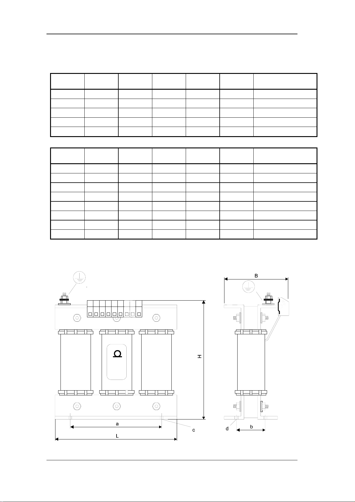
Accessories Installation
Dimensions
Isolating
transformer
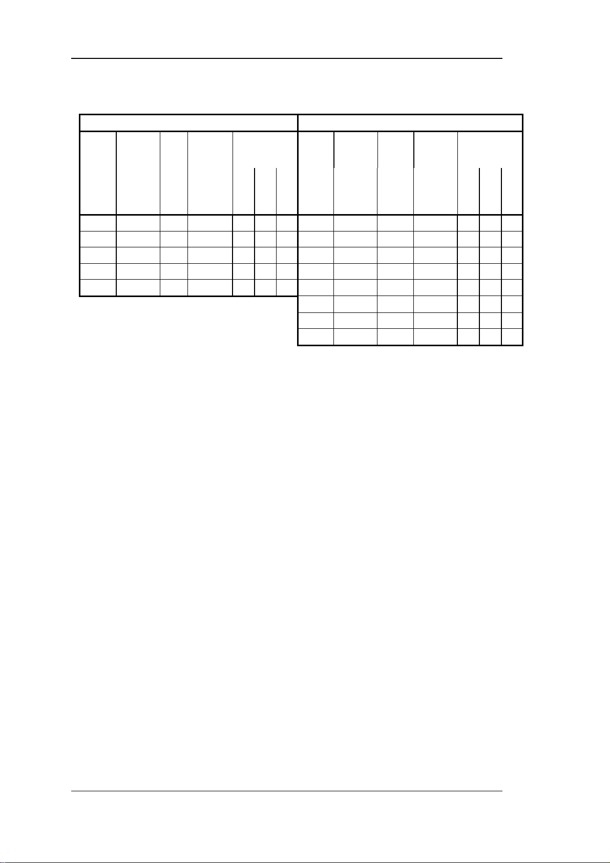
19007154 0.4 180 110 155 7.5 136x55 / 7.0x14
19007155 1.0 204 140 175 15.0 175x85 / diam. 8.5
19007156 2.5 240 160 205 22.5 200x100 / diam. 8.5
19007157 5.0 360 195 305 68.0 300x130 / 9x14
19007158 8.0 360 210 305 77.0 300x150 / 9x14
Autotrans-
former
19007159 0.4 150 75 130 4.2 113x48 / 5.8x11
19007160 1.0 180 110 175 7.5 136x56 / 7.0x14
19007161 2.5 204 140 200 15.0 175x85 / 7.0x14
19007162 5.0 240 160 225 22.5 200x100 / 9.0x14
19007163 8.0 270 170 255 27.0 220x105 / 8.5x12
19007165 10.0 270 170 250 29.0 220x105 / 9.0x14
19007166 15.0 340 210 305 51.0 280x110 / 12.0x8.5
19007167 25.0 400 210 385 78.0 340x130 / 9.0x14
Power
(kVA)
Power
(kVA)
Length L
(mm)
Length L
(mm)
Breadth W
(mm)
Breadth W
(mm)
Height H
(mm)
Height H
(mm)
Weight W
(kg)
Weight W
(kg)
Fastening/Hole
axb / cxd (mm)
Fastening/Hole
axb / cxd (mm)
BUG 3/2/20 Basic Feed Unit 31
Baumüller Nürnberg GmbH 5.96064.02
Page 40
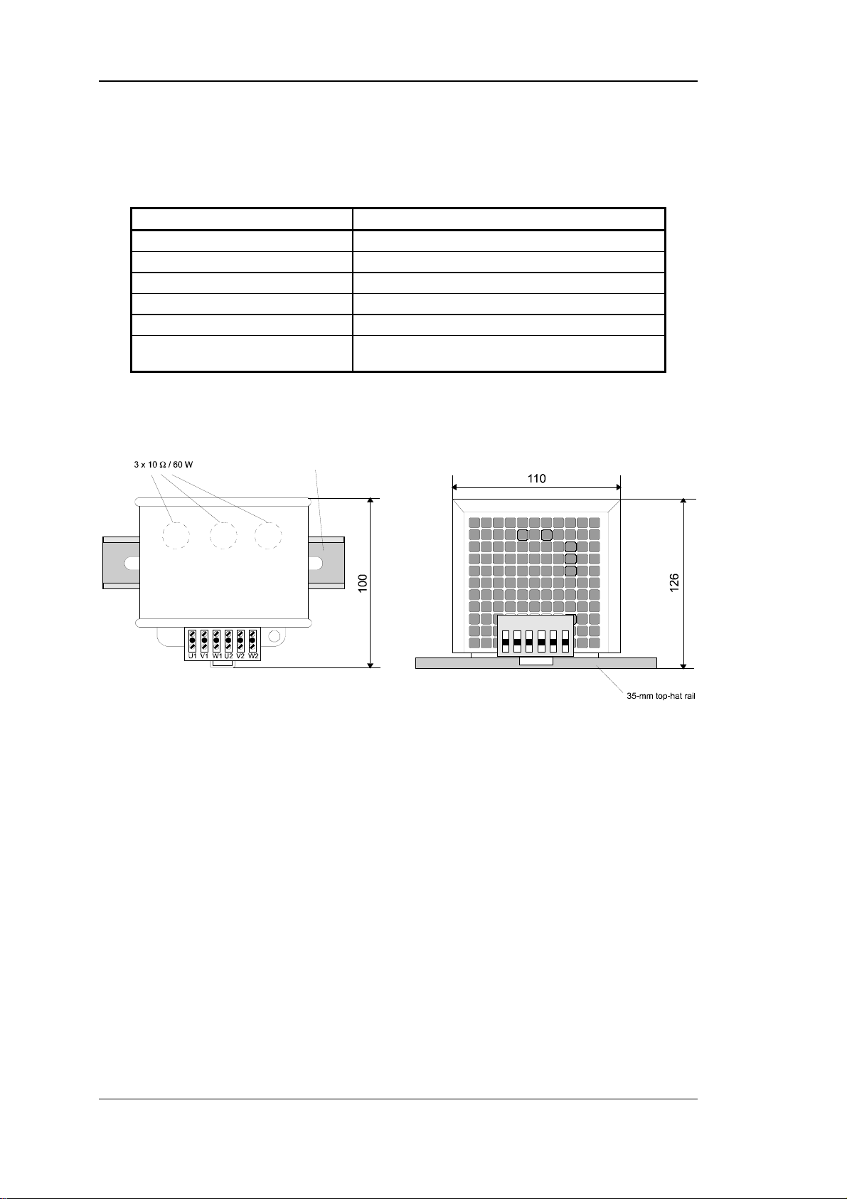
Installation Accessories
5.5.2 Starting Current Limitation Device
Technical Data
Type Designation WSV 3 - 10/60 - 001
Resistor 3 x 10 Ω
Rated Power 3 x 60 W
Reclose after 2 s
Max. closing energy 350 Ws
Max. capacitance at U
Overload protection by safety circuit
breaker with auxiliary switches
Dimensions
=340 V 6 mF
ZKmax
Rated current 2 A
Trip curve C
32 BUG 3/2/20 Basic Feed Unit
5.96064.02 Baumüller Nürnberg GmbH
Page 41
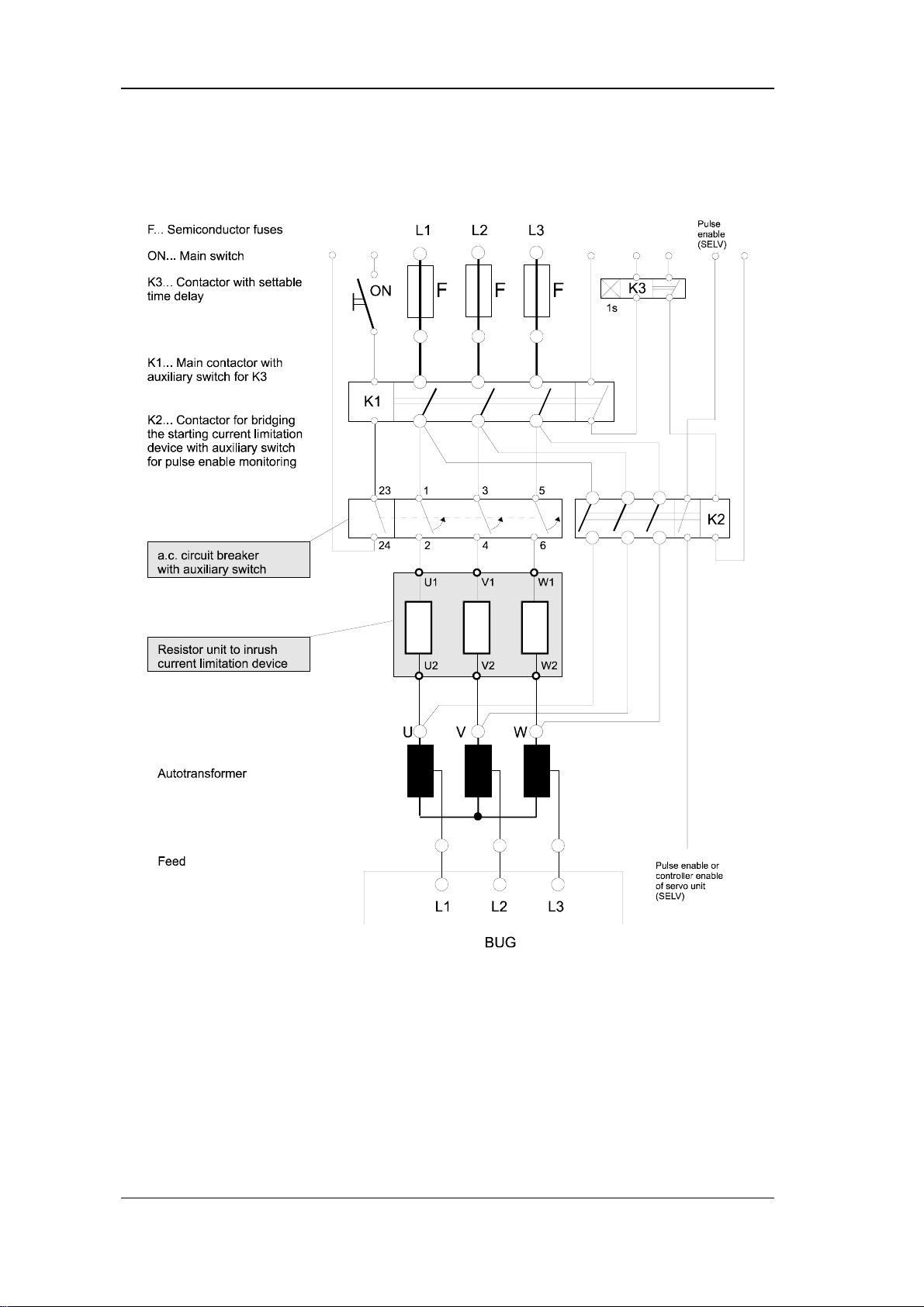
Accessories Installation
Connection Suggestion
BUG 3/2/20 Basic Feed Unit 33
Baumüller Nürnberg GmbH 5.96064.02
Page 42
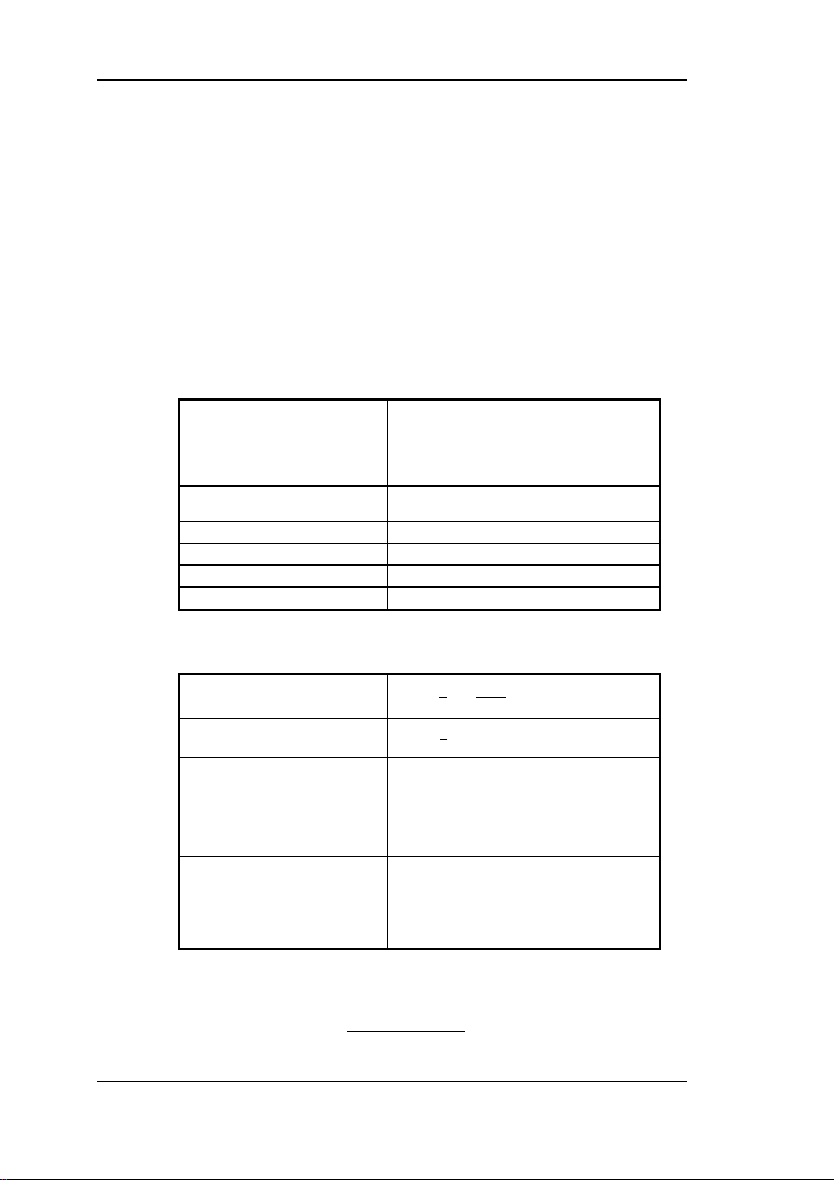
Installation Accessories
5.5.3 BUR Resistor Unit
Device Description
During the braking stage of converter-fed three-phase current drives, the system initially loads
the device-internal intermediate circuit capacitors with the fed-back electrical energy.
If there is still electrical energy available after loading, it can be additionally stored in an external capacitor unit or converted to heat via device-internal or device-external resistors. Specifically for the latter purpose, a Type Series 6 device is provided that combines the resistors in a
force-ventilated way in a safe housing.
Electrical specifications
1)
Resistor
Rated Power PV ≤ 2 kW,
Peak Power PV ≤ 18 kW for t ≤ 15 s
Max. permissible ballast energy 270 kWs
Operating environm. temperature T
Coolant temperature range T
Storage temperature range -30 ... +70 °C
1)
When UL508C is considered: The resistor-units are only to
be used in connection with Baumüller-appliances of BUG and BUM61, 62 and 62T types.
BUG20
BUG2
BUG3
K
R = 4 Ω
R = 8 Ω
R = 16 Ω
force ventilated, T
P
0 ... 45 °C
B
0 ... 45 °C
≤ 36 kW for t ≤ 7 s
V
= 45 °C, mounted vertically
A
Calculation
Kinetic energy
Stored energy
Ballast energy WV = PV * t
The following are stored in the capacitor
with BUG 3 and BUG 21
with BUG 20 and BUG 2
BUK capacitor unit
The following are burnt out in the
ballast resistor
Ballast BUG 3
BUG 2
BUG 20
Ext. ballast BUR
1
WJ
=
**
m
2
1
WCUU
=−
m
2
W
= 3.8 Ws/unit
el
W
= 17.25 Ws/unit
el
W
= 345 Ws/unit
el
W
= 13.5 kWs P
el
W
= 24 kWs P
el
W
= 55 kWs P
el
W
= 270 kWs P
el
**
2
n
*π
2
60
2
()
221
= 200 W
eff
= 400 W
eff
= 900 W
eff
= 2 kW
eff
In cyclic operation, the power P of the ballast resistors is not to be exceeded.
tPtP
...
+⋅+⋅
P
=
2211
t
ges
34 BUG 3/2/20 Basic Feed Unit
5.96064.02 Baumüller Nürnberg GmbH
Page 43
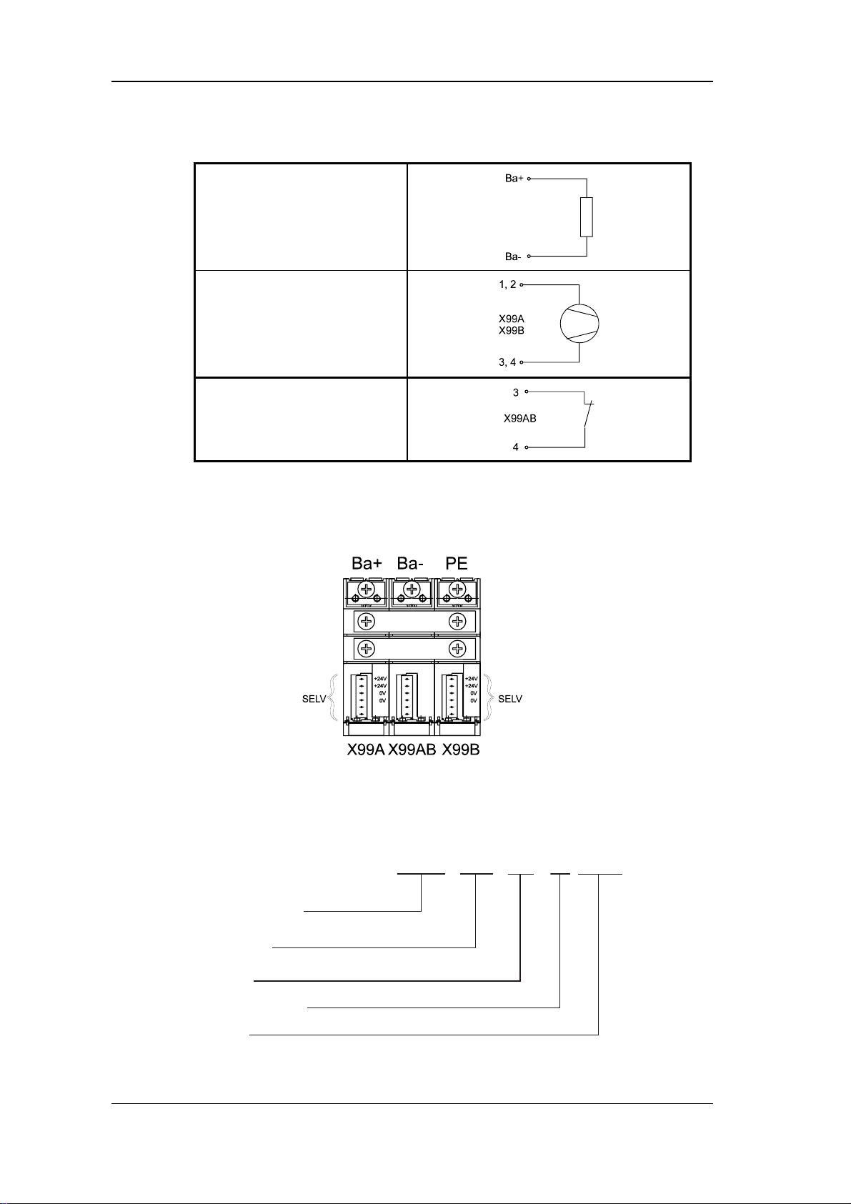
Accessories Installation
Connection
Connect ballast resistor connector
to basic unit (refer to connection
plan of basic unit)
Fan (24 VDC, 0.25 A, SELV)
Pre-warning Error
(Overrtemperature BUR) (SELV)
1)
When UL508C is considered: The resistor-units are only to
be used in connection with Baumüller-appliances of BUG and BUM61, 62 and 62T types.
1)
Connections
Type Code
B U R - 6 2 2 - 0 4 - 2 - 0 0 0
0 8
1 6
BAUMOTRONIC
Resistor Unit
Type Seri es
Type
Resistor
Rated power 2 kW
Ver sion
BUG 3/2/20 Basic Feed Unit 35
Baumüller Nürnberg GmbH 5.96064.02
Page 44
Installation Accessories
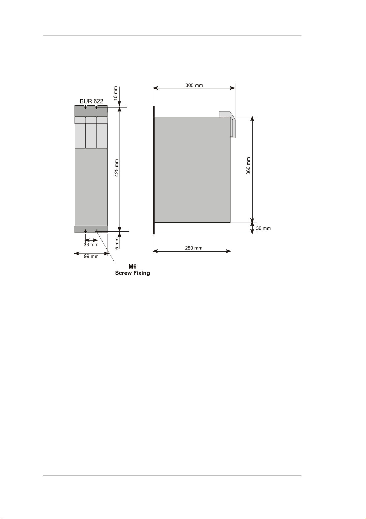
Dimensions
36 BUG 3/2/20 Basic Feed Unit
5.96064.02 Baumüller Nürnberg GmbH
Page 45
Accessories Installation
5.5.4 BUK Capacitor Unit
Device Description
In the case of converter-fed three-phase current drives that are primarily used as acceleration
drives, e.g. as transverse cutting drives, it is frequently practical to supplement the internal
intermediate circuit capacitor by adding an external capacitor unit. This makes it possible to
store the energy that is fed back at braking of the drive.
Due to the use of a capacitor unit, it may be possible to replace a ballast unit that normally
converts the fed-back energy to heat. In addition, a capacitor unit is always used in cases
where the intermediate circuit voltage must be maintained during brief mains failures.
BUK external capacitor units are integrated in Type Series 6 housings and are available for
intermediate circuit voltages of 310 V and 540 V.
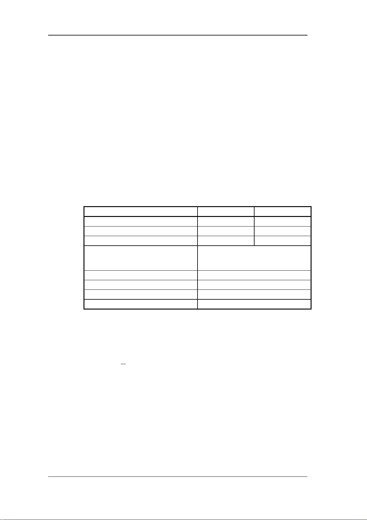
Electrical Data
Type BUK 622 - 31 - 20 BUK 622 - 54 - 05
Capacitance 20 mF 5 mF
Rated voltage 310 V
Max. intermediate circuit voltage 400 V
Charging current limitation by use of basic unit
Permissible charging time per capacitor unit t > 1 s
Discharge time t > 10 min
Ambient temperature range T
Storage temperature range -30 ... +70 °C
K
Calculation
Energy storage capacity during braking
WCUU
1
=−
**
el
2
()
2
221
U1 = intermediate circuit voltage before braking
U2 = intermediate circuit voltage after braking
DC
DC
varies depending on type series
(for this, refer to description of basic unit)
0 ... 45 °C
540 V
800 V
DC
DC
This gives a storage capacity at braking of:
BUK 622 - 31- 20: approx. 640 Ws (U1 = 310 V, U2 = 400 V)
BUK 622 - 54- 5: approx. 870 Ws (U1 = 540 V, U2 = 800 V)
BUG 3/2/20 Basic Feed Unit 37
Baumüller Nürnberg GmbH 5.96064.02
Page 46
Installation Accessories
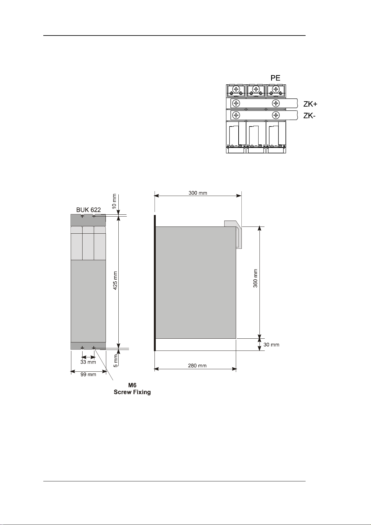
Connection
To intermediate circuits ZK+ and ZK-
− with short 10-mm² wires for Series 2/20 type
− with short 4-mm² wires for Series 3 type
deenergized.
Dimensions
38 BUG 3/2/20 Basic Feed Unit
5.96064.02 Baumüller Nürnberg GmbH
Page 47

Accessories Installation
Type Code
B U K - 6 2 2 - 3 1 - 2 0 - 0 0 0
5 4 - 0 5 - 0 0 0
BAUMOTRONIC
Condenser Unit
Type Seri es
Size
Rated Voltage
310 V or 540 V
Capacity 20 mF at 310 V
5 mF at 540 V
Design 000: standard
xxx: customized
BUG 3/2/20 Basic Feed Unit 39
Baumüller Nürnberg GmbH 5.96064.02
Page 48

Installation Accessories
40 BUG 3/2/20 Basic Feed Unit
5.96064.02 Baumüller Nürnberg GmbH
Page 49

Commissioning
6 COMMISSIONING
WARNING
Plants that have drive converters installed, must have additional monitoring and protection devices
according to the respective regulations, e.g. technical equipment regulations, safety precautions etc.
Alterations of the drive converters or the operation software are prohibited.
This equipment carries a dangerous voltage and contains dangerous rotating parts (fans). Ignoring the
safety and warning information may result in death, severe personal injury or damage to property.
Only qualified personnel which has been instructed with all safety-related information as well as the
mounting-, service- and maitenance instructions given in this document is allowed to operate this device.
You are responsible for mounting the Mono power unit, the motor and any other equipment in accordance with appropriate safety regulations (e.g. DIN, VDE); equally, you must ensure that all other
relevant national and local regulations are met with regard to cable ratings and protection, grounding,
disconnectors, overcurrent protection, etc.
The most important factors for protecting people are the DIN/VDE protective measures and safety
regulations. If there are no protective earth connections on the equipment, commutating reactor or the
motor, personal injuries are inevitable, since the surfaces may carry dangerously high voltages.
The mains unit and the field connector of the power converter carry a dangerous voltage even when
the main contactor has dropped. Do not touch these modules when under power. Connect test equipment only in powerless state!
After the drive converter is separated from the power supply you must not touch any connectors as
they still might carry dangerous loads. Observe the waiting time given on the danger sign information
on the drive converter.
During operation, the principles on which the power converter and the motor work lead to leakage
currents to earth that are dissipated via the specified protective earths and may result in a currentoperated e.l.c.b on the input side blowing prematurely.
In the case of a short-circuit to frame or to ground, a direct proportion may arise in the leakage current
that makes triggering a higher level current-operated e.l.c.b. either more difficult or totally impossible.
The connection of the converter to mains using only an e.l.c.b. is prohibited (refer to pr EN
50178:1994 section 5.2.11.2 and appendix A 5.2.11.2 diagram 7).
Before carrying out commissioning, check whether the plastic covers over the power stage connections are in place.
The appliances are only to be operated on earthed mains systems.
The discharge time of the power conducting parts is more than 1 minute.
BUG 3/2/20 Basic Feed Unit 41
Baumüller Nürnberg GmbH 5.96064.02
Page 50

Commissioning
WARNING
Irregular drive behavior
During initial commissioning, faulty or uncontrolled motion of the driven machine elements is always
possible. At this stage, you should therefore proceed with particular care.
Before switching on the drive, you must carefully check the functions of all the higher level safety
equipment to prevent personal injury.
Take particular care when directly or indirectly touching the drive shaft with your hand. This is only
allowed when the shaft is stationary and the power converter is deenergized. Any exposed parts of the
machine, such as the shafts, fans, etc., must be covered during operation.
Contact Protection In Accordance with Paragraph 4 Section 4 VBG 4 (German safety regulation)
Protection against direct contact comprises all the measures against danger that can result from
touching the active parts of electrical equipment.
You must therefore protect the active parts from being touched by means of insulation, the construction
and arrangement of the equipment or directly mounted guards. The guards in question are standard
covers, barriers and procedures that guarantee that people cannot touch active parts that are carrying
power.
Switching cabinets must have an emergency off facility to switch off any voltages that could be dangerous. This does not include equipment which, if switched off, would cause an even more dangerous
situation. The emergency off releasing element must be arranged in such a way that it can be reached
quickly in case of danger. In the case of work that is considerably more dangerous than usual, another
person must be present.
The operator must ensure that unauthorized people do not work at the machine.
The operator must report immediately any changes that occur at the machine which adversely affect
safety.
When dismounting safety equipment during commissioning, repair and maintenance, you must ensure
that the machine is taken out of commission in accordance with applicable regulations. You must remount and check safety equipment immediately after completing commissioning, repair and maintenance.
42 BUG 3/2/20 Basic Feed Unit
5.96064.02 Baumüller Nürnberg GmbH
Page 51
Commissioning
WARNING
Follow the safety information on the motor, tachometer and further electrical appliances in the respective operating and maintenance instructions.
Avoid any working practices that jeopardize safety at the machine.
After carrying out any work involving intervention in the drive – regardless of whether this involves the
motor, actual value acquisition or the power converter – the owner must carry our acceptance testing
of the machine and document it chronologically in the machine log (maintenance manual or similar).
Failure to do this may result in the owner being faced with consequences relating to liability legislation.
This is not a complete list of all the procedures necessary for safe operation of the unit. If you need
further information or have particular problems, contact BAUMÜLLER NÜRNBERG or one of our distributors.
Observe the warning information in chapter 1 of these operating instructions.
NOTE
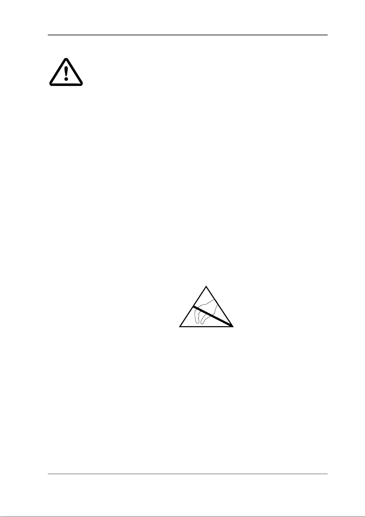
• Before touching the modules, you must discharge electrostatic energy from your body to protect
electronic components from high voltages resulting from electrostatic charging. The easiest way to
do this is to touch a grounded conductive object before handling components.
Units containing components or modules at risk from electrostatic energy are clearly marked as
such by the sticker below.
BUG 3/2/20 Basic Feed Unit 43
Baumüller Nürnberg GmbH 5.96064.02
Page 52
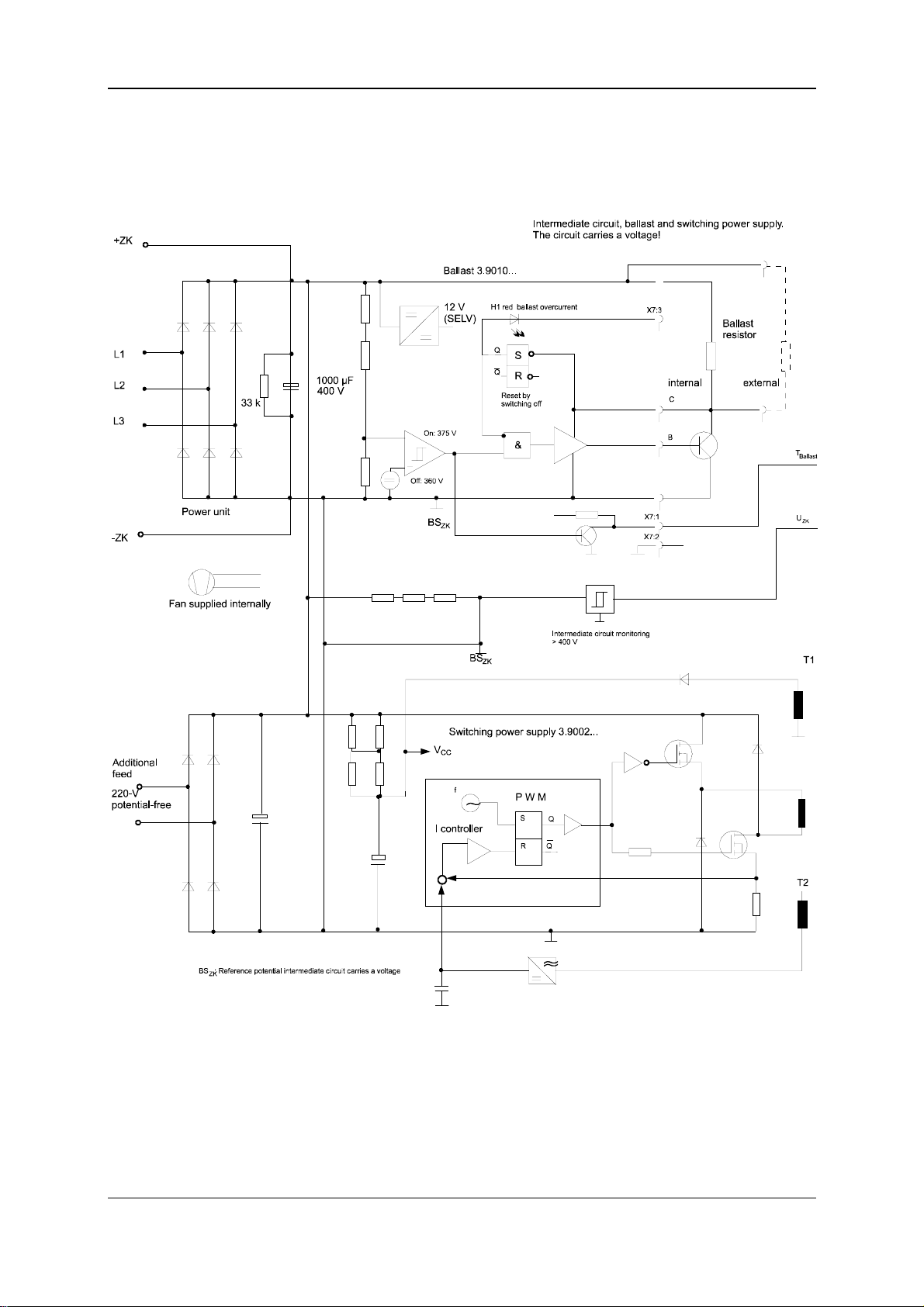
Commissioning Function diagram
6.1 Function diagram
44 BUG 3/2/20 Basic Feed Unit
5.96064.02 Baumüller Nürnberg GmbH
Page 53
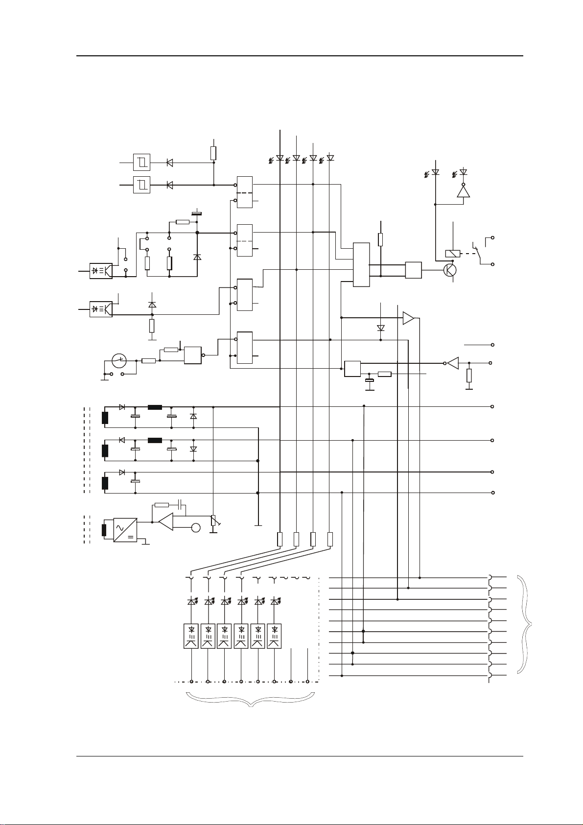
Function diagram Commissioning
LED H204 ... 206 with BUG 20 only
W201: fitted with external ballast
W202: fitted with BUG 2/3 (t = 1.5 s)
W203: fitted with BUG 20 (t = 1.8 s)
+15 V
(SELV)
-15 V
(SELV)
+
W201
++
W202
W203
L with
10% dev.
L: Uzk > 400 V
+
L: t > x
H204 red: t > x s
++
Error store
Q
S
Q
R
Q
S
Q
R
Q
S
Q
R
ballast
H203 red: U > 400 V
ZK
H205 red: +/- 15 V not OK
H206 red: Temp. > 72° C
H202 green: ready-for-use system
H201 red: system error
+
+
X1:7 (SELV)
X1:8
&
&
Contact closed
on ready-for-use
(SELV)
Te mp .
switch
W204
T1
T2
PAM
Test adapter BU: Connect via connector
on the bottom of the device
H1 red - not
connected
H1 red - not
connected
H3 red TKK temperatu re
of power unit too high
H4 red +/- 15-V supply
voltage not correct
H5 red Uzk intermediate circuit
voltage > 400 V
H6 red TB ballast resistor
overload ed
-
U controller
+
&
L: Temp. > 92° C
(BUG 2)
S
R
+15 V
-15 V
+24 V
Ground
=
1
2346789
H6
H5 H4 H3 H2 H1
X27
6543
7
SELV
Q
Q
BSs
+10 V
-15 V -10 V M +15 V
21
10
UU
s
s
0
X1:2
+24 V
(SELV)
Clear memory
(SELV)
&
Switch-on
reset
+15 V +15 V
-15 V -15 V
BSa, BSn - Reference potential analog or n controller BSa, BSn
+
System b us X9
SLS - Clear memory SLS
BBS - Ready -for-use system BBS
RFS - Controller enable system RFS
X1:1
X1:4
X1:5
X1:6
X1:3
10
9
8
7
6
5
4
3
2
1
+15 V (SELV)
-15 V (SELV)
+24 V (SELV)
BSa (SELV)
Res+
Res-
+15 V
-15 V
SELV
BUG 3/2/20 Basic Feed Unit 45
Baumüller Nürnberg GmbH 5.96064.02
Page 54

Commissioning Messages and Warnings
6.2 Messages and Warnings
On the front panel of the Basic Feed Unit, there are six LEDs that indicate the messages listed below.
These messages are stored and you can reset them by either switching on again or by a Reset on
terminal strip X1 (contacts 1,2).
Possible messages:
System error
Ready-for-Use
Intermediate Circuit
Ballast
Controller Supply
Temperature
• Ready-for-Use
If no message is pending, the green ready-for-use LED is lit and the system reports this condition
to the servo units. If only one message of the BUS servo units is pending and the group message
on the servo units is activated in the BEDAS, the system cancels ready-for-use and does not indicate any further messages.
• Intermediate Circuit
If the intermediate circuit voltage exceeds the set limit value, the system issues a message and
displays it. Ready-for-use is cancelled.
This message is issued in the following cases:
− braking energy is greater than P
maxBallast
− ballast circuit is missing
− wrong or defective external ballast resistor
46 BUG 3/2/20 Basic Feed Unit
5.96064.02 Baumüller Nürnberg GmbH
Page 55

Messages and Warnings Commissioning
• Ballast
Ballast monitoring supervises the switching frequency of the ballast transistor. If the maximum time
exceeeds the internally set time, the system issues a message and cancels ready-for-use.
This message is issued in the following cases:
− if the braking power is too high
− if the continuous power of the ballast resistor is too high
− if the short-time loading is longer than two seconds
− if the intermediate circuit voltage due to the mains overvoltage is greater than 375 V
• Controller Supply
Controller supply monitoring supervises the internal switching power supply for overloading and
brief short-circuits. If one of these errors occurs, the system generates a message and cancels
ready-for-use.
• Temperature
Overtemperature monitoring supervises the temperature of the heatsink. If this temperature exceeds an internally set limit value, the system issues a message and cancels ready-for-use.
This message is issued in the following cases:
− if the input rectifier is overloaded
− if the fan is blocked
− if the ambient temperature is too high
• System error
If the system issues one of the messages listed above, it is stored and displayed as the System error group message.
The system cancels ready-for-use and reports it to the connected servo units.
NOTE
You cannot clear messages whose disturbances are still pending.
BUG 3/2/20 Basic Feed Unit 47
Baumüller Nürnberg GmbH 5.96064.02
Page 56
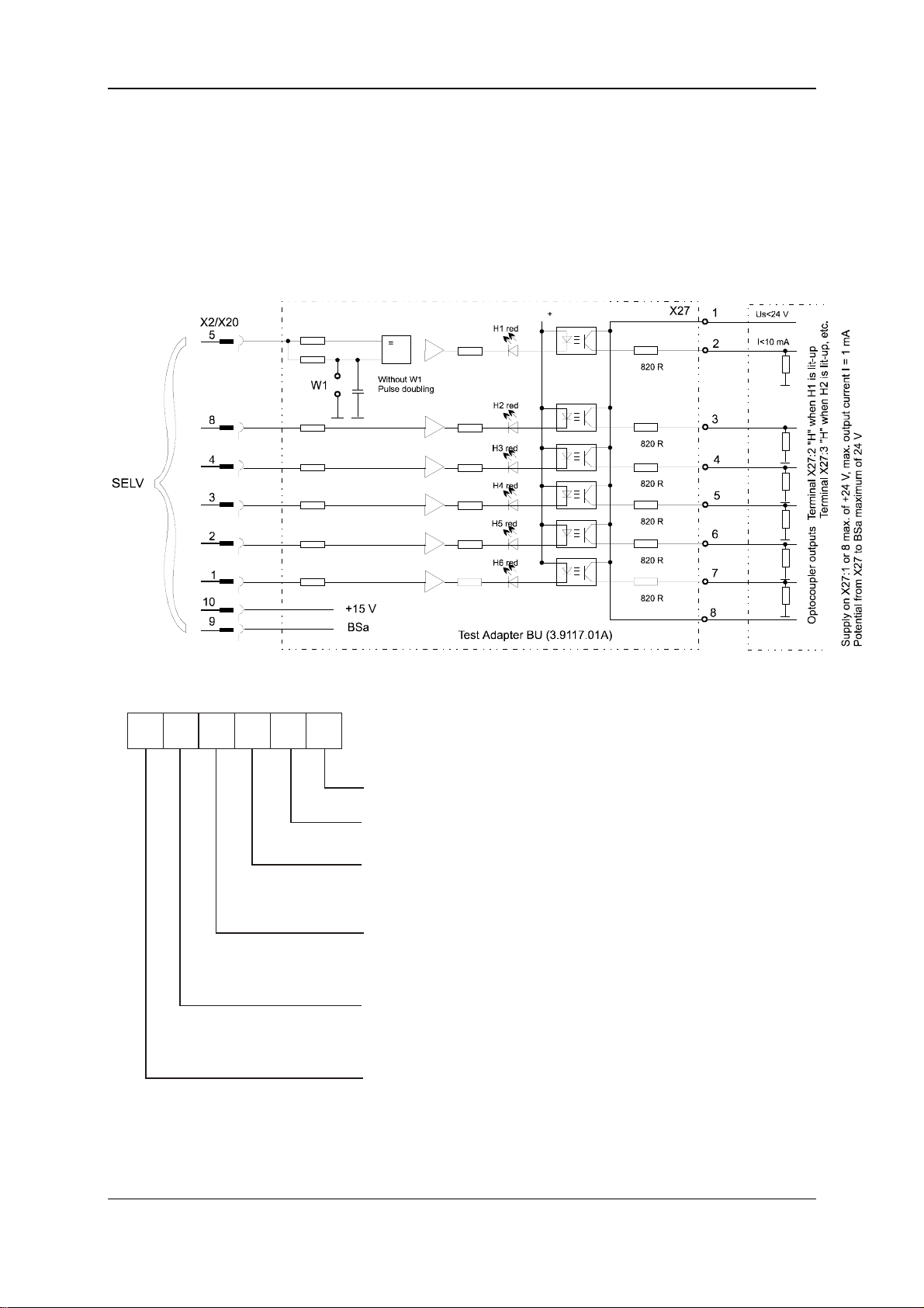
Commissioning Test Connector
6.3 Test Connector
The test connector is situated at the bottom of the unit behind a cover-plate. By use of this it is possible to poll individual messages by means of the optional BU test adapter and to display or transfer
them to higher-level controllers using an optocoupler.
Error Evaluation
H6 H5 H4 H3 H2 H1
Not connected
Not connected
LED TKK is lit-up or optocoupler
output (X27:4) High
LED +/-15 V is lit-up or optocoupler
output (X27:5) High
LED Uzk is lit-up or optocoupler
output (X27:6) High
LED T is lit-up or optocoupler
B
output (X27:7) High
- Input recitfier overload
- Fan is blocked
- Ambient temperature too high
- Supply voltage o
- Brief short-circuit of
supply voltage
- Braking energy > Pmax
- Ballast circuit defective or missing
- W xternal ballast resistor rong e
- Braking power too high
- Continuous power of ballast resistor
too great
- Brief load > 2 s Pmax
- Intermediate circuit voltage > 375 V due
to mains voltage
verload
48 BUG 3/2/20 Basic Feed Unit
5.96064.02 Baumüller Nürnberg GmbH
Page 57

Maintenance Information Maintenance
7 MAINTENANCE
WARNING
This appliance carries a dangerously high voltage and has dangerous rotating parts (fans). Ignoring
the safety and warning information may result in death, severe personal injury or damage to property.
You may only carry out maintenance and corrective maintenance work when the equipment is
deenergized.
Do not begin work on the power stage and the connections until you have made sure that the system
has been deenergized.
After switch-off wait until the intermediate circuit is fully deenergized.
When dismounting safety equipment during commissioning, repair and maintenance work, you must
ensure that the machine is taken out of commission in accordance with applicable regulations. You
must remount and check safety equipment immediately after completing commissioning, repair and
maintenance work.
After carrying out any work involving intervention in the machine – regardless of whether this involves
the motor, the actual value acquisition or the power converter – the operator must carry out acceptance testing of the machine and document it chronologically in the machine log. Failure to do this may
result in the owner being faced with consequences relating to liability legislation.
Due to technical requirements, devices or motors may include individual components that contain
dangerous substances.
You may only use manufacturer-approved spares.
We cannot guarantee that the product documentation is completely error–free
unless this is expressly indicated in our General Conditions of Business and
Supply.
7.1 Maintenance Information
The supplied units are maintenance-free.
Prohibition of Unauthorized Modifications
For safety reasons, unauthorized additions or modifications to the drive are not allowed.
BUG 3/2/20 Basic Feed Unit 49
Baumüller Nürnberg GmbH 5.96064.02
Page 58
Maintenance Disposal
7.2 Disposal
The equipment consists mainly of the following components and materials:
Component Material
Housing, various intermediate panels, fan impeller, mounting
panels
Heat sink of the power section Aluminium
Various spacer bolts Steel
Various spacers, housing of current converter and unit fan,
etc.
Bus bars in the power stage Copper/aluminium
Cable harnesses PVC- or Teflon-insulated copper wire
Power electronics: Module diodes mounted on a heat sink Metal base plate, semiconductor chip, plastic
PCBs on which all the open- and closed-loop electronics are
mounted
Sheet steel or aluminium
Plastic
housing, various insulation materials
Base material: Epoxy-resin fibreglass woven
material, copper-coated on both sides and
plated-through, various electronic components
such as condensors, resistors, relays, semiconductors, etc.
For technical reasons, electronic components might need to contain dangerous materials, so you
should not open them.
If the components are used correctly, there is no danger to human beings or to the environment.
In case of fire, dangerous compounds can be generated or released.
You must dispose of or recycle equipment or components according to national regulations as well as
any applicable local or regional ordinances.
50 BUG 3/2/20 Basic Feed Unit
5.96064.02 Baumüller Nürnberg GmbH
Page 59

Appendix
8 APPENDIX
8.1 Manufacturer Declaration
Manufacturer Declaration in Accordance with
the EC–Machine Guidelines 89/392/EEC, Appendix II B
We herewith declare that this delivery includes the following specified machine component and that its
putting into operation is prohibited until the declaration is made that the machine, in which this component is built in, complies with the regulations of the EC–machine guideline 89/392/EWG, appendix II B.
Specification of the machine component: Type:
Basic Feed Unit BUG - 3 - 35 - 31 - . - ...
BUG - 2 - 60 - 31 - . - ... - ..
BUG - 20 - 120 - 31 - . - ...
Date/Signature of the Manufacturer: Nürnberg, 4. März 1997
Information regarding the Undersigned: Head Division Electronics
BUG 3/2/20 Basic Feed Unit 51
Baumüller Nürnberg GmbH 5.96064.02
Page 60

Appendix
8.2 Declaration of Conformity
EG Declaration of conformity
of equipment regarding
low voltage directive 73/23/EWG
Specification of the machine component: Type:
Basic Feed Unit BUG - 3 - 35 - 31 - . - ...
BUG - 2 - 60 - 31 - . - ... - ..
BUG - 20 - 120 - 31 - . - ...
Conformity of the significated product with the guidelines will be proved by following rules:
pr EN 50178: 1994 (VDE 0160/11.94)
"Equipment of power installation concerned electronic operating materials"
Nürnberg, 8. January 1997
Signature of the Manufacturer
Dr.–Ing. P. Kreisfeld Dipl.–Ing. (FH) R.–A. Geller
Head Division Electronics
CE–Agent Electronic
52 BUG 3/2/20 Basic Feed Unit
5.96064.02 Baumüller Nürnberg GmbH
Page 61

8.3 Conditions of Business and Delivery
Appendix
1. Scope
1.1 Deliveries and performance provided by Baumüller and of fers made by Baumüller are
exclusively and completely subject to thes e general terms and conditions (from now on referred to as ''these terms"). Unless a mutual agreement has been made which differs from this
statement, these terms also apply to futur e business relationships.
1.2 If a customer places an order with Baumüller, this implies that these terms are accepted. Any
counterconfirmations made by persons or legal persons placing an order with Baum üller with
reference to their own general term s and conditions or their term s and conditions of purchase
are thereby objected to.
1.3 Supplements or modifications to these terms require written consent from Baumüller in order
to take effect.
2. Offer and Copyright
2.1 Offers made by Baumüller are subject to confirm ation and not binding. Supplements,
modifications or ancillary agreem ents require written consent from Baumüller in order to take
effect.
2.2 Any pictures, drawings, measures, weights or other perform ance specifications are only
binding if this is explicitly stipul ated in writing. Drawings, dimensional dra wings and descriptions of projects are subject to the cop yright of Baumüller and must neither be copied nor revealed to third parties without prior written consent from Baumüller. Baumüller reserves the
right to demand that these objects are immediately returned to Baumüller if they are not us ed
for orders to Baumüller.
2.3 The purchaser must not use any process engineering knowledge re vealed to him in his
business relationship with Baum üller for his own purposes and must not re veal that k nowledge to third parties. Any violation of this condition makes the purchaser (violator) liable for
damages of an amount of DM 70,000.
3. Scope and Term of Delivery
3.1 The deadlines and terms specified by Baum üller are not binding unless explicit ly specified
otherwise in a written agreement.
3.2 The delivery term begins at one of the points in time listed below:
− Date of confirmation of order
− Date on which the purchaser meets all of the technical, commercial or other
prerequisites he is obliged to m eet
− Date on which a downpayment or security required prior to deliver y of the
merchandise is furnished by the purc haser
− If the stipulated downpayments to Baumüller are made delaye d, the delivery term is
extended proportionally.
3.3 Baumüller has the right to make partial deliveries and prov ide partial performance and to issue
partial invoices for these deliveries or performance at any time of their choice. Exces s volume
or short deliveries up to 5% of the deliver y quantity are permitted. The amount charged is c alculated according to the delivery qua ntity.
3.4 Baumüller is not responsible for delayed delivery or p erformance or the inability to deliver or
perform due to acts of god or force majeure or other eve nts which make it impossible or more
difficult for Baumüller to deliv er - e.g. war, problems in the provision of materials which arise
after the time the offer has been made, m alfunctions, strike, lockout, personnel short age,
shortages of means of transportation, instruc tions issued by the authorities etc. which occur at
suppliers of Baumüller or their sub-s uppliers. Therefore, Baumüller has the right to postpone
deliveries or performance by the durat ion of the problem plus an appropriate startup tim e and
Baumüller also has the right to withdra w from the contract partially or completel y. If the problems persist for more than 3 months the pur chaser has the right to withdraw from that part of
the contract which has not yet been f ulfilled after having fixed an appropriate extens ion of the
time limit.
3.5 The deadline is considered to have been met if the object to be delivered leaves the st orage
facility on the fixed date or if the purchaser is inform ed of its availability for shipment on the
fixed date.
3.6 Baumüller or subcontractors of Baumüller will install and assem ble the delivered objects
exclusively subject to conditions and terms separately agreed upon not later than 4 weeks
before delivery.
4. Passage of risk, ac ceptance, packing
4.1 Delivery is made free carrier (FRC, lNCOTERM 1980). The goods are packed at the discretion
of Baumüller at the costs of the custom er. The risk is passed to the customer as soon as t he
consignment has been handed over to the per son carrying out the transport or has left the
store.
4.2 If the shipment is delayed or becomes impossible due to reasons for whic h Baumüller is not
responsible, the risk is passed to the c ustomer with the notification of readiness for s hipment if
the delivery is stipulated to be carried out upon call-forw ard notice, the goods are regarded as
called off at the latest one year after th e date of order.
4.3 Special acceptance conditions must be defined at c onclusion of the contract at the latest. The
acceptance test has to take place in the works of Baumüller. The costs for the acceptance test
will be charged to the customer. If the cus tomer omits the acceptance test, the goods are regarded as delivered as stipulated when they leave our works.
5. Prices and terms of payment
5 1 The prices stipulat ed by Baumüller in the order confirmation plus t he respective legal value
added tax apply. Additional deliveries and servic es will be separately invoiced. The prices are
valid ex works or store excluding pac king.
5 2 If not otherwise agreed upon, the prices stipulated in the order confirmation are binding for 30
days only.
5 3 Payments shall be made in cash without any deductions free paying office of the vendor in t he
currency agreed upon. Bills of exchange and ch ecks are only accepted on account of payment. The customer has to bear any costs and bank charges arising thereof.
A payment is regarded as made only, if the am ount is available to Baumüller. In case of payment by check, the payment is regarded as made when the check has been irrevocably
cashed.
5 4 Invoices are to be paid without deductions within 30 days from the date of issue. Baumüller is
entitled to enter payments of the cust omer on older open invoices in spit e of deviating instructions by the customer. If costs and interests have ahead arisen. Baumüller is entitled to enter
the payment first on the costs, then on the i nterests and last on the main service.
5.5 The customer is entitled to offset, to retain or red uce the payment - independent of notices of
complaint or possible countercla ims - only, if Baumüller has explicitly agr eed or if the counterclaims have been legally verifie d.
5.6 If payments are delayed, Baumüller is entitled to charge interest on arre ars at a rate corresponding to the interest rate for open cred its in current account, however, at least corresponding to the current discount rate of the Deutsche Bundesbank.
This does not affect the assertion of anot her damage caused by delayed payment.
5 7 If the customer fails to meet his payment obligations, esp ecially if he does not cash a chec k or
stops his payment or if Baumüller is informed of other circumstances making the cr edit worthiness of the customer uncertain. Baumüller is entitled to demand advance payments or secur ities before delivery or to invoice th e total remaining amount in the case that ins talments had
been previously agreed upon.
6. Retention of owners hip
6 1 Until all claims for present or future relations have be en satisfied, Baumüller can at
any time demand securities from the custom er. Baumüller will arbitrarily release provided securities
if the value of the securities continuousl y exceeds the claims b y more than 20%.
6.2 Any goods delivered remain property of Baumüller u ntil payment has been made in full (=
delivery under proviso). Goods delivered under pr oviso are processed or reconfigured at
the purchaser's for Baumüller as the manuf acturer but without add itional obligations. If
Baumüller ownership rights are nullified becaus e the goods are integrated into or assembled to other objects, a portion of the owner ship rights of th e purchaser to that object
covering the amount in question is transferred to Baumüller. The purchaser k eeps the
property of Baumüller in custody for no charges.
6.3 The purchaser has - unless he is in delay of payment - the right to pr ocess and sell the
goods delivered under proviso in norm al business. However, he must not distress or
transfer ownership of the goods deliver ed under proviso by way of security. T he purchaser transfers any receivables aris ing from the selling of the goods or from another legal reason completely to Baum üller when the goods are received. Baumüller revocabl y
entitles the purchaser to collect the recei vables transferred to Baumüller o n the account
of Baumüller under his own name. Upon request b y Baumüller, the purchaser will revea l
the transfer.
6.4 If third parties access the goods delivered under prov iso, the purchaser will inform them
about the ownership rights of Baumüller and will immediately inform Baumüller. Any expenses and damages are paid for by the p urchaser.
6.5 If the purchaser violates any of the terms of the contrac t - in particular if he is in dela y of
payment - Baumüller has the right to repos es the goods delivered under proviso at the
cost of the purchaser or Baumüller has the right to requir e transfer of the restitution title
the purchaser has against third parties. If Baumüller r epossesses or distresses the goods
delivered under proviso, this does not m ean that Baumüller withdraws from the contract.
The right to receive payment for damages r emains unaffected by this.
7. Warranty
7.1 If the delivered products are faulty or fail to have pro perties guaranteed by Baumüller or if
the products become defective during th e warranty period because of faults which occurred or were caused during the process of manufacturing or in case of material defects
Baumüller supplies - excluding any other warra nty claims by the purchaser, in partic ular
excluding any direct or indirect secondary claims for damages from the purc haser - replacement parts of their own choice or rec tifies defects. Multiple rectification is permitted.
For essential products and parts not m anufactured by Baumüller - in particular if the
purchaser has made specifications - the liabilit y of Baumüller is limited to the transfer of
the claims for damages Baumüller has against the supplier of these products or parts.
7.2 The warranty period is 12 months and starts on the day the goods are shipped to the
purchaser or - if the delivery scope is installed and as sembled by Baumüller - the war-
ranty period starts on the day the install ation is complete.
7.3 The purchaser is obliged to inspect the delivered goods for damages or defects imm ediately or at least within two weeks after receiving the goods or - if the pr oduct is installed within two weeks after completion of the installation proces s. In addition, he is obliged to
inform Baumüller of any damages, def ects or losses immediately by sending a report
created by the carrier or a corresponding report in the form of a statement in lieu of an
oath which must have been signed by two witnesses and by the purchaser. In addit ion,
Baumüller must be informed in writing of obvious defects or shortcom ings immediately or
at least within two weeks after delivery. If shortcomings and def ects cannot be detected
in thorough tests within two weeks and are found at a later time, Baumüller m ust be informed of these problems immediatel y after they are detected. Defective products must
be submitted to Baumüller for testing on reques t in the condition in which the defect was
detected. Defective products must not be retur ned to Baumüller unless Baumüller requests in writing that the products are returned. Failure t o observe any of the regulations
specified above nullifies all warr anty claims against Baumüller.
7.4 If rectification or replacements are not succes sful within an appropriate period of time,
the purchaser may either request reduc tion of the purchase price or cancellatio n of the
delivery contract.
7.5 If Baumüller manufactures a product based on des ign specifications, drawings, m odels
or other specifications provided by the purchas er, Baumüller is responsible only for the
fact that the manufactured product meets the specifications. Baumüller is not responsible
for the usability of the product for the pur poses the purchaser intends to use it for.
7.6 Excluded from warranty are shortcomings or defects caused by inst ructions/and or as sembly not effected by Baumüller, insuf ficient equipment of the customer, overload of the
components exceeding the capacity spec ified by Baumüller, neg ligent and improper
treatment and utilization of unsuitable operati ng materials at the customer. This also applies to shortcomings or defects arising due to m aterial provided b y the customer. The
warranty does not apply to damages caused by third parties, atmospheric discharges,
overvoltages and chemical influenc es or to the replacement of par ts which are exposed
to natural wear.
The warranty is void if the custom er or a third party changes or repairs the units del ivered
without written permit by Baumüller.
7.7 In case of guarantee and/or warranty claims, the motor, the spare part or the unit shall be
shipped free of duty and with free packing after prior agre ement with Baum üller.
Baumüller is freed of any warrant y, if the customer returns the defective pro ducts without
prior agreement or without observing t he arrangements.
7.8 Baumüller is entitled to install spare parts and un its into the plants of the customer for
warranties to be fulfilled within the warranty period, in order to replace the defective
products so that the efficiency of the customer's parts is af fected as little as possible.
The warranty period for installed spar e parts and units is 6 months from the date of re-
placement at the customer. Taking into ac count the service time for the deliv ered prod-
ucts, the warranty period of 12 months from date of deliv ery acc. to item 7.2 remains unchanged.
8. Liability
8.1 Baumüller is liable for information and consultin g activities on the utilization of the or-
dered and delivered products only with written confirm ation in accordance with the below
regulations. Verbal statements and inf ormation are not binding.
8.2 Claims for damages due to impossibility of perf ormance, nondelivery, positive breach of
obligations, culpa in contrahendo an d unlawful act to Baumüller as well as to the persons
employed in performing an obligatio n are excluded, if the damage has
not been caused deliberately or grossly ne gligent or Baumüller is liable according to the
product liability law.
9. Lump-sum damages in cas e of withdrawal
If the customer withdraws from the writt en order due to reasons for whic h Baumüller is
not responsible, Baumüller is entitled to charge lump-sum damages of 50% of the net order amount. This applies also, if Baumüller withdr aws from the contract due to reasons
for which the customer is respons ible.
10. Miscellaneous
10.1 Place of fulfilment and juris diction is Nuremberg. However, Baumüller is entitled to ad-
vance claims at the legal place of jur isdiction of the customer.
10.2 The legal regulations applic able in the Federal Republic of Germ any are applicable to
these conditions and terms of sales and delivery. The r egulations or the UN law of sales
are excluded.
10.3 If one or several regulations of these conditions and terms of sales and delivery are or become
ineffective or if any arising situation and circumstances are not covered by this contract text, jurisdiction will replace or supplement the ineffective or incomplete stipulations by appropriate
regulations corresponding to the economic purpose of the intended regulation to the largest possible extent. The validity of the other regulations remains unchanged.
BUG 3/2/20 Basic Feed Unit 53
Baumüller Nürnberg GmbH 5.96064.02
Page 62

Appendix
8.4 Index
A
Appendix • 53
Assembly Information • 16
B
Block diagram • 7
C
Cable screens • 21
Commissioning • 41
Conditions of Business and Delivery • 55
Connection voltage • 8
Control Terminals • 28
Coolant temperature range • 8
D
DANGER • 2
Danger Information • 2; 17
Degrees of contamination • 16
Discharge Currents • 23
Disposal • 52
E
Earth circuits • 21
Electrical Data • 8
EMC information • 18
I
Initial Commissioning • 42
Installation • 17
M
Maintenance • 51
Manufacturer Declaration • 53
N
NOTE • 2
P
Personnel, qualified • 3
Power Terminals • 28
S
Safety information • 1
Screening • 22
T
Technical Data • 5
Temperature of coolant • 16
Transportation • 11
Type Code • 10
F
Filter Assembly • 23
Filtering • 23
G
Grounding • 21
U
Unpacking • 11
Use, appropriate • 3
V
Ventilation • 16
W
WARNING • 2
54 BUG 3/2/20 Basic Feed Unit
5.96064.02 Baumüller Nürnberg GmbH
 Loading...