

Baumr-AG FUJI-MICRO F5200Ri, FUJI-MICRO F4200Ri, Genforce GT6000, Genforce GT400, Genforce GT3000 User Manual
Fuel-Injected Petrol Powered Inverter
Generators
User Manual
[Revision 1.0 October 2016]
RETAIN THIS MANUAL FOR FUTURE REFERENCE
PLEASE READ THIS MANUAL CAREFULLY BEFORE USE

Fuel-Injected Petrol Powered Inverter Generators
It is important that you read and
General Work Area Safety
Use the equipment and accessories etc. in
Safety
Safety messages are designed to alert you to possible dangers or hazards that could cause death, injury or
equipment or property damage if not understood or followed. Safety messages have the following symbols:
You WILL be KILLED or
SERIOUSLY INJURED if y ou do
not follow instructions.
understand the instruction manual before
use and keep the manual in a safe place
for future reference. Safety information
presented here is generic in nature – some
advice may not be applicable to every
piece of equipment.
All safety precautions must be observed to
reduce the risk of personal injury when
operating the equipment.
The term “equipment" refers to your
product, be it electrical mains, battery or
petrol engine powered.
IMPORTANT – Handle the equipment
safely and carefully.
BEFORE USE - If you are not familiar with
the safe operation/handling of this
equipment, or are in any way unsure of any
aspect of suitability or correct use it for
your application, you should complete
training conducted by a person or
organization qualified in safe use and
operation of this equipment, including
fuel/electric al handling and saf ety.
WARNINGS
• Read all safety warnings and all
instructions. Failure to follow warnings
and instructions may result in electric
shock , fire a nd/or serio us injur y.
• Never run a petrol engine in confined
areas.
• Do not operate the equipment in
flammable or explosive environments,
such as in the presence of flammable
liquids, gases or dust. Engine and
equipment may create sparks or heat
that may ignite vapors, dust etc
• Keep clear of moving parts.
• This equipment may be a potential
source of electric shock if misused.
• Do not operate the equipment if it is
damaged, malfunctioning or is in an
excessively worn state.
• Do not allow others to use the
equipment unless they have read this
manual and are adequately trained.
• When using the equipment, basic
safety precautions detailed here must
always be followed to reduce the risk
of fire, electric shock, personal injury
and material damage.
• When wiring electrically powered
equipment, follow all electrical and
safety codes.
• Ensure all power source s conform to
equipment voltage requirements and
are disconnected before connecting
equipment.
You CAN be KILLED or
SERIOUSLY INJURED if you do
not follow instructions.
Work areas should be clean and well it .
Do not operate the equipm e nt if
bystanders, animals etc are within
operating range of the equipment or the
general work area.
Personal Safety
Keep packaging away from children - risk
of suffocation! Operators must use the
equipment correctly. When using the
equipment, consider conditions and pay
due care to persons and property.
Prevent unintentional starting of the
equipment - ensure equipment and power
source switches are in the OFF position
before connecting or moving the
equipment. Do not carry equipment with
hands/fingers touching any controls.
Remove any tools or other items that are
not a part of the equipment from it before
sta r ting o r s witching on.
Stay alert and use common sense when
operating equipment. Do not overreach.
Keep proper footing and balance at all
times. Do not use equipment when tired or
under the influence of drugs, alcohol or
medication. This equipme nt is not intended
for use by persons with reduced physical,
sensory or mental capabilities.
You must wear appropriate protective
equipment when operating, servicing, or
when in the operating area of the
equipment to help protect from serious
injury, including eye injury, inha lat ion of
toxic fumes, burns, and hearing loss.
Always wear eye protection. Protective
equipment such as respirators, non-skid
safe ty shoes, har d hat, hearing protection
etc should be used for appropriate
conditions. Other people nearb y sho uld
also wear appropriate personal protective
equipment. Do not wear loose clothing or
jewellery, which can be caught in moving
parts. Keep hair and clothing away from
the equipment.
If devices are provided for the connection
of dust extraction and collection facilities,
ensure these are connected and properly
used. Use of dust collection can reduce
dust-related hazard s.
General E quipment Use and Ca re
Do not force the equipment. Use the
correct equipment for your appl icatio n. The
correct equipment will perform better and
be safer within its design parameters. Do
not use the equipment if the ON/OFF
switch malfunctions – any equipment that
cannot be controlled with the ON/OFF
switch is dangerous and must be repaired.
You CAN be INJURED if you do
not follow instructions or
equipment damage may occur.
accordance with these instructions, taking
into account working conditions and the work
to be performed. Using the equipment for
operations different from those intended
could result in hazardous situatio ns.
Before use, inspect the equipment for
misalignment or binding of moving parts,
loose components, damage or any other
condition that may affect its operation. If
damaged, have the equipment repaired by an
authorized service center or technician before
use.
Always keep the equipment and accessories
(cutting tools, nozzles, bits etc) properly
maintained. Keep the equipment, controls
and handles dry and free from dirt, oil and
grease.
Store the equipment out of reach of children
or untrained persons. To avoid burns or fire
hazards, let the equipment cool completely
before transporting or storing. Never place
the equipment in places where there are
flammable materials, combustible gases or
combustible liquids etc.
The equipment is not weatherproof, and
should not be stored in direct sunlight, at high
ambient temperatures or locations that are
damp or very humid.
Generator Use and Car e
WARNINGS
• If the generator is for back-up
power to a house etc, it must be
connected to the building electrical
system by a qualified electrician
and must comply with relevant laws
and electrical codes. If not
connected correctly, use of the
generator may present
electrocution, electric shock,
explosion and fire hazards.
• The generator creates high voltage
and current electricity. Do not
connect incompatible devices.
• Never insert any object other than
compatible connectors into any
generator output connector.
• Do not operate the equipment with
wet hands or clothing.
• When using the generator, ensure
to keep it and all connected cables
away from other electrical cables.
• Operate the generator on solid,
level surfaces only, with at le ast 1m
(3’) between it and other equipment
or objects.
2
Fuel-Injected Petrol Powered Inverter Generators
General Fuel Safety
Petrol/fuel/gasoline is extremely
flammable – keep clear of
naked flames or other ignition
sources.
• Do not spill fuel. If you spill fuel, wipe
it from equipment immediately – if fuel
gets on your clothing, change them
immediately
• Do not smoke near fuel.
• Always shut off the engine before
refuelling.
• Do not refuel a hot engine.
• Open the fuel cap carefully to allow
any pressure build-up in the tank to
release slowly.
• Always refuel in well ventilated areas.
• Always check for fuel leakage. If fuel
leakage is found, do not start or run
the engine until all leaks are fixed.
General Service Information
• Have the equipment serviced or
repaired at authorized service centers
by qualified personnel only.
• Replacement parts must be original
equipment manufacturer (OEM) to
help ensure that equipment safety is
maintained.
• Do not attempt any maintenance or
repair work not described in this
instruction manual.
• After use, the equipment and
components may still be hot – allow
the equipment to cool and disconnect
spark plugs and/or el ectrical power
sources and/or batteries from it before
making adjustments, changing
accessories or performing repair or
maintenance.
• Do not make adjustments while the
equipment is running.
• Perform all service related activities
under suitable conditions, such as a
workshop etc.
• Replace any worn, damaged or
missing warning labels immediately.
• Do not clean equipment with solvents,
flammable liquids or harsh abrasives.
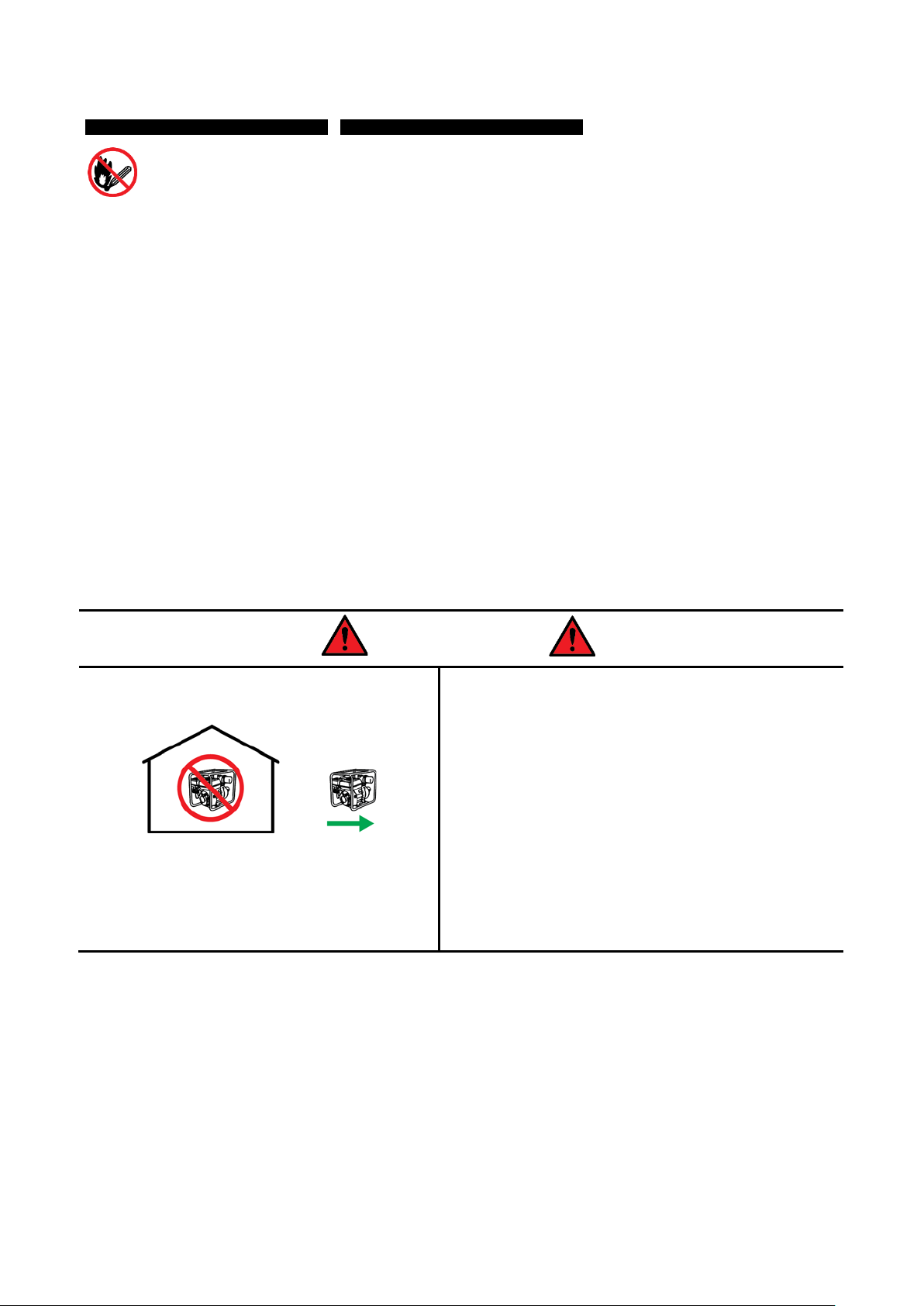
DANGER
Running petrol engines in confined areas CAN KILL IN
MINUTES. Engine exhaust fumes contain carbon-
monoxide – a deadly gas that you cannot smell or see.
NEVER run a petrol engine in confined areas EVEN IF
windows and doors are open. ONLY run petrol engines
OUTDOORS and away from doors, windows and
vents.
Do not operate the equipment in hazardous locations,
such as where there may be a risk of fire or explosions
from flammable liquids, gases or dust.
Do not operate the equipment in confined areas where
exhaust gases, smoke or fumes could reach dangerous
concentrations.
Do not refuel petrol engines while they are running.
Never smoke while refuelling petrol engines.
For generators, the electrical output is potentially lethal
and must only be connected to a fixed electrical
installation by an appropriately licensed person.
Be aware that the equipment may include hazardous
components, such as blades, hot surfaces and moving
parts.
3

Fuel-Injected Petrol Powered Inverter Generators
Table of Contents
Safety ................................................................................................................................................... 2
Appli cable Models ............................................................................................................................. 5
Parts I dentificat ion ............................................................................................................................. 6
Accessories ................................................................................................................................................ 7
Before Use Checklist ......................................................................................................................... 8
4-Stroke Engine Oil .................................................................................................................................... 8
Air Filter ...................................................................................................................................................... 8
Fuel ............................................................................................................................................................ 8
Engine Starting and Generator Operation ...................................................................................... 9
Starting and Stopping the Engine .............................................................................................................. 9
Operating the Generator .......................................................................................................................... 10
Understanding Rated Output ............................................................................................................. 10
Calculating Generator Load ............................................................................................................... 11
Grounding the Generator ................................................................................................................... 12
Generator Status Indicators ............................................................................................................... 12
AC Applications ................................................................................................................................. 12
DC Applications ................................................................................................................................. 13
Maintenance ..................................................................................................................................... 14
Maintenance Schedule for Fuel-Injected 4-Stroke Engines ..................................................................... 14
Checking and Changing Engine Oil ......................................................................................................... 15
Checking, Cleaning or Replacing the Air Filter ......................................................................................... 17
Air Filter Inspection and Cleaning ...................................................................................................... 17
Air Filter Removal/Installation ............................................................................................................ 17
Maintaining the Spark Plug ...................................................................................................................... 18
Spark Plug Cleaning and Gap Checking ........................................................................................... 18
Spark Plug Removal/Installation ........................................................................................................ 18
Transportation and Storage ............................................................................................................ 19
Preparing for Transport and Storage........................................................................................................ 19
Long Term Storage .................................................................................................................................. 19
Troubleshooting ............................................................................................................................... 20
Specifications ................................................................................................................................... 22
150cc Engines ......................................................................................................................................... 22
105cc Engines ......................................................................................................................................... 22
53cc Engines ........................................................................................................................................... 22
Generator Specifications .......................................................................................................................... 23
Service and Maintenance Record .................................................................................................. 24
4
Fuel-Injected Petrol Powered Inverter Generators
Applicable Models
This manual applies to the following generators:
Fuji Micro F5200Ri 150cc 3.2kW
Genforce GT6000 124cc 3.2kW
Genforce GT3000 53cc 1.7kW Bäumr-AG
Fuji Micro F4200Ri 105cc 2.5kW
Genforce GT4000 105cc 2.5kW
5
Fuel-Injected Petrol Powered Inverter Generators
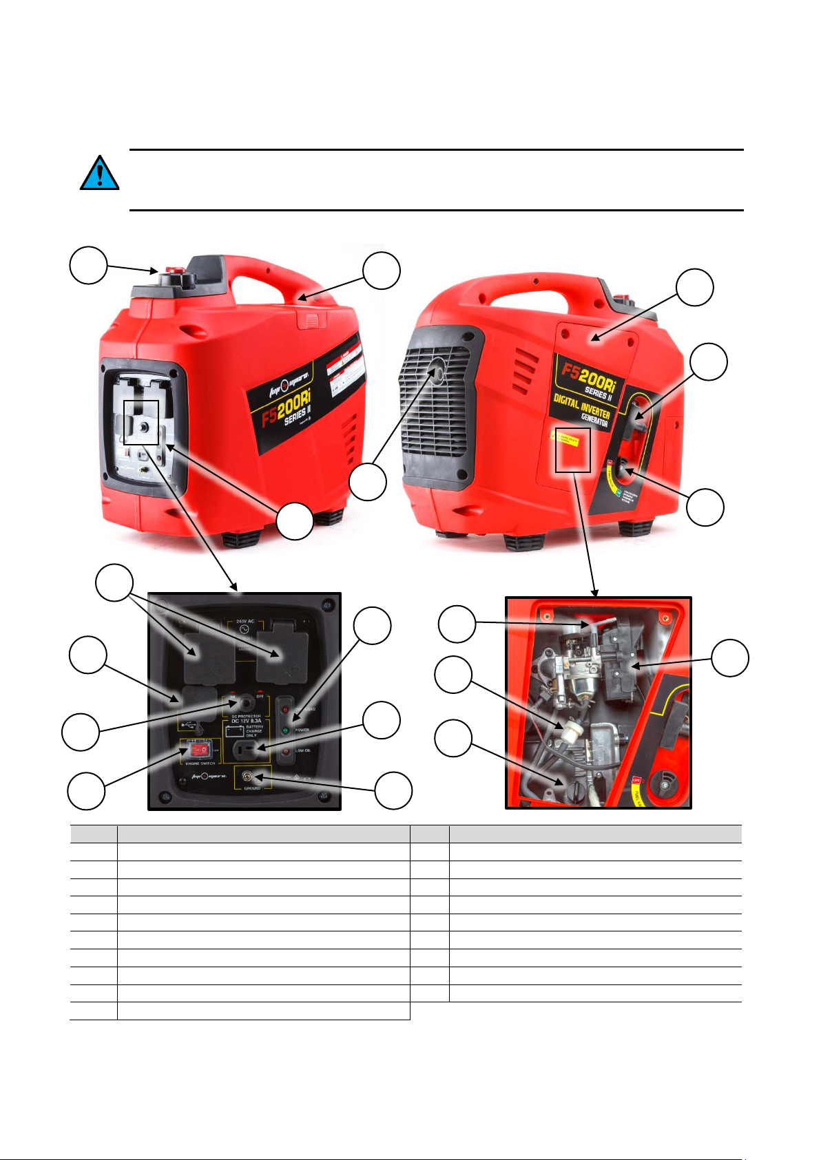
No.
Name
No.
Name
1
Control Panel
11
USB Device Connector(s) (under cover)
2
Fuel Filler
12
240VAC Output Socket(s) (under cover)
3
Exhaust
13
Machine Status Indicators
4
Spark Plug Access Cover (plug inside)
14
12VDC Output Connection
5
Carry Handle
15
Ground Connection
6
Engine Access Cover
16
Oil Filler/Dipstick
7
Starter Cord
17
Fuel Filter
8
Fuel Tap (fuel strainer inside)
18
Air Filter Cartridge (filter inside)
9
Engine ON / OFF Switch
19
Choke
10
12VDC Output Protection Reset Switch
1
3
4
6
7
Parts Identification
Products detailed in this manual may vary in appearance, inclusions, description and packaging
from those shown or described. This section shows typical major components common to most fuelinjected petrol powered generators.
2
11
10
9
12
13
8
19
18
17
14
16
15
6
Fuel-Injected Petrol Powered Inverter Generators
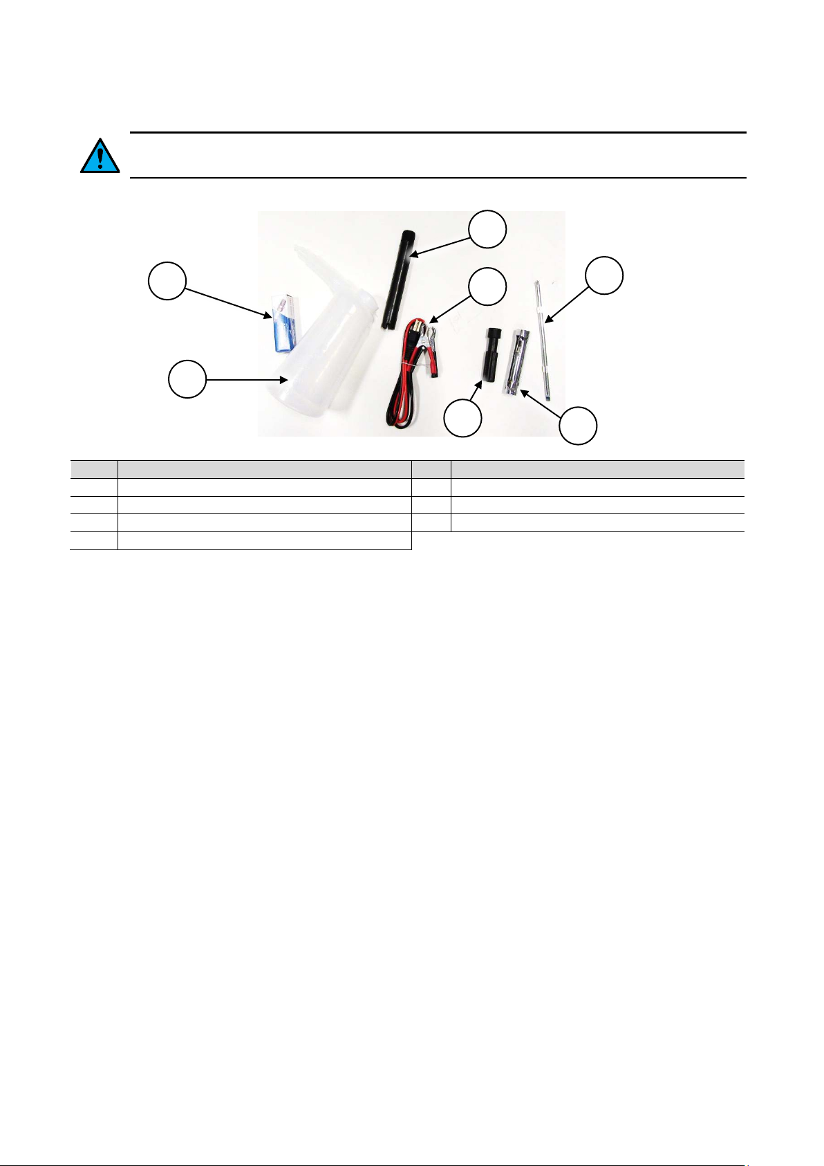
No.
Name
No.
Name
1
Oil Fill Bottle
5
Screw Driver
2
Oil Drain Tube
6
Screw Driver Handle
3
12VDC Battery Charging Cable
7
Spark Plug (spare)
4
Spark Plug Socket
Accessories
The accessories listed below are provided as a guide only. Not all models may include all or any
accessories..
2
7
3
5
1
6
4
7

Fuel-Injected Petrol Powered Inverter Generators
Before Use Checklist
Ensure that you carry out all procedures below before starting the engine or operating the w ater
pump. Failure to follow the checklist and carry out the procedures correctly may result in
making the product warranty void.
4-Stroke Engine Oil
Four-stroke engines require engine oil in the crankcase for lubrication of internal components. Severe or
irreparable damage may occur if the engine is allowed to run without engine oil. The engine oil level requires
regular maintenance. Check the engine oil level and ensure that the oil level is at or just under the maximum
level indicator.
Always check the engine oil level before starting the engine. See Checking and Changing Engine Oil.
Air Filte r
The air filter is used to prevent dirt and other particles from possi bly entering the engine and causing internal
damage to it. The air filter requires regular maintenance.
Always check the air filter before starting the engine. See Checking, Cleaning and Replacing the Air Filter.
Fuel
Petrol/fuel/gasoline is extremely flammable – keep clear of naked flames or other ignition
sources. • The engine must be cool before refuelling.
Adequately fill the fuel tank with the correct fuel type.
• Use non-ethanol unleaded (higher RON values will provide best engine performance). Do not use old or
contaminated fuel.
To fill or top up fuel:
1. Place the machine in an upright position on a flat and level surface.
2. Clean the machine around the fuel filler so that no dirt or other material enters the engine when the cap
is removed.
3. Remove (rotate left) the fuel filler cap.
4. Using a funnel, carefully fill the tank with fuel. Do not fill above the top of the strainer (if equipped) or
otherwise overfill the tank.
5. When finished, reinstall (rotate right) the fuel filler cap until firm. Wipe away any residual fuel from the
machine. If fuel has been spilt, move the machine away from the spillage before starting the engine.
8

Fuel-Injected Petrol Powered Inverter Generators
A B C
D
Engine Starting and G ener at or O per a tion
Before starting the engine, ensure that you have followed all procedures described in the Before
Use Checklist. • Before starting the generator, disconnect all output sockets so that no load is
immediately placed on the generator as it starts up.
Different models may feature variations in design; for example, some have different engine t ypes, etc. The
following procedures and images are typical to all models, however, the position or appearance of controls
etc may vary. All major engine controls are identified on the machine by way of stickers or other markings.
Once the engine is started, the engine speed will automatically regulate depending on connected load. For
example, under high loads, the engine may run at a higher speed.
Starting and Stopping the Engine
1. FUEL – Place the fuel tap (A) in the “ON” position and on the fuel filler cap, place the fuel vent (B) in the
“ON” position.
2. IGNITION – Place the engine ON/OFF switch (C) in the “ON” (“I”) position.
3. START – Slowly pull out the starter cord (D) until you feel it engage with the engine, then pull it out
rapidly. Hold the generator handle firmly when pulling the starter cord to prevent the machine toppling
over. The engine should start. Allow the starter cord to rewind slowly – do not let it “snap” back.
If the engine does not start, repeat step 3. If the engine fails to start after several attempts, refer to
Troubleshooting.
Using the Choke
In very cold conditions, if the normal starting procedure is
not working, choke may be required to help start the engine.
To use the choke:
1. Remove the engine access cover (E).
2. Rotate the choke lever (F) toward the rear of the
machine – this is the “COLD” or “START” position.
3. Start the engine as normal. As the engine warms up,
slowly rotate the choke lever back towards the front of
the machine – this is the “HOT” or “RUN” position.
4. Once the choke is fully in the “HOT” or “RUN” position,
re-install the engine access cover.
NOTE: If the engine cannot be started, check the engine oil le v el before any other troubleshooting as the low
oil safety mechanism may be preventing the engine from starting.
Stopping the Engine
1. OUTPUTS – Turn OFF any connected devices, then unplug them from the generator.
2. IGNITION – Place the engine ON/OFF switch in the “OFF” (“O”) position.
F
E
3. FUEL – Place the fuel tap in the “OFF” position and on the fuel filler cap, place the fuel vent in the “OFF”
position.
Click to Watch:
9
Inverter Generator Set-Up - Mytopia
Inverter Generator Set-up - Edisons

Fuel-Injected Petrol Powered Inverter Generators
•
•
Operating the Generator
• Ensure that the generator is grounded (eart hed) before using it.
• Allowing the generator to run when being overloaded may permanently damage the unit
and/or shorten its service life and may void product warranty.
• Ensure that any device to be powered by the generator is switched OFF before connecting it to the
generator.
• Ensure that all devices that will be powered by the generator are electrically safe and functioning normally.
If at any time a connected device appears to malfunction, stop or slow down etc, immediately switch the
generator and device OFF and disconnect the device.
• Do not exceed the rated power output of the generator. Consider the power rating for all connected
devices that will be running simultaneously, both AC and DC, and ensure that the sum of all power
consumption is no more than the generator rated output with consideration given to actual power output
based on altitude and temperature (see Understanding the Rated Output). For example, 2 x 1200W devices
will be acceptable for a 2.5kW rated output generator, however, will overload a 2kW unit.
• Do not exceed the rated current for the output socket. For example, do not connect a device that draws
15A to a 10A socket.
• If using an extension cable, ensure it is an approved type and has a minimum wire gauge of 1.5mm² up to
a cable length of 60m; 2.5mm² up to a cable length of 100m.
• For appliances that place high “inductive” loads when being started or stopped (for example, electric
motors), consideration should be given to the rated output of the generator and the required inductive load
capacity. Rated output equates to approximately 45 to 75% of inductive load capacity.
• Do not connect devices in parallel to the generator.
• Devices sensitive to input voltage fluctuation should be connected via a suitable surge protector.
Understanding Rated Output
The “rated output” is described as the maximum power that the generator can consistently and reliably
provide. The rated output of a generator is based around several factors including altitude, ambient
temperature and relative humidity. The specified rated output is calculated at an altitude of 0m, ambient
temperature of 25°C and relative humidity of 30%. Deviations from these values will affect the actual output
capacity of the generator. For example, if the generator is used at high altitude it will produce less power.
Basically the higher the altitude, the warmer the ambient temperature and the greater the humidity, the less
power can be produced. The following table provides a guideline for calculating actual generator output
based on ambient temperature and altitude [note that humidity is ignored here as it has a marginal effect]:
Altitude (m)
0
500
1000
2000
3000
4000
25 30 35 40 45
1 0.98 0.96 0.93 0.90
0.93 0.91 0.89 0.87 0.84
0.87 0.85 0.82 0.80 0.78
0.75 0.76 0.71 0.69 0.66
0.64 0.62 0.6 0.58 0.56
0.54 0.52 0.5 0.48 0.46
Ambient Temperature (°C)
Power Output Coefficient
Examples:
At an approximate altitude of 1000m and 30°C ambient temperature, the power output coefficient is 0.85.
So, a rated output of 2.5kW becomes 2.5 x 0.85, which equates to an actual power output of 2.125kW.
At an approximate altitude of 2000m and 25°C ambient temperature, the power output coefficient is 0.75.
So, a rated output of 2.0kW becomes 2.0 x 0.75, which equates to an actual power output of 1.5kW.
10

Fuel-Injected Petrol Powered Inverter Generators
•
Lamp
Radio
Television
Computer
Laptop
Oven
Slow Cooker
Blender
Tools
Electric Fan
Deep Fryer
Lamp
Iron
Music Play e r
(small)
Toaster
Cleaner
Video Play e r
Machine
Water Heater
Water Pump
Maker
Hair Drye r
Video Gam e
•
At an approximate altitude of 3000m and 40°C ambient temperature, the power output coefficient is 0.58.
So, a rated output of 2.0kW becomes 2.0 x 0.58, which equates to an actual power output of 1.16kW.
Calculating Generator Load
Most electrical devices clearly state the required power, usually in Watts (W). This information is generally
labelled on the device, or listed in its user manual. If a device lists power consumption figures in amperes
(A) only, calculate the wattage by multiplying the ampere rating by the voltage. For example, a 10A device @
240VAC equates to 2400W (10A x 240V). The sum of all devices required to be operating simultaneously
needs to equal or be less than the rated output of the generator.
Many devices require a different load on start-up/shut-down that is often much higher than the actual
continuous running requirements. For example, a water pump may require 2000W to start, and once started,
requires 500W to continue running. When calculating generator load, the start-up requirements need to be
factored in. If the start-up power consumption is not known, the table below lists typical consumption figures
for several device types that may assist in determining how many or which devices may be connected and a
starting order [that is, start the high consumption devices first, followed by devices with no additional start-up
power requirements].
Start-up Watts 50 to 150 100 to 200 150 to 500 800 200 1400
Running Wa t t s 50 to 150 100 to 200 150 to 500 800 200 1400
Start-up Watts 250 850 1000 to 1500 600 800 to 2000 N/A
Running Wa t t s 250 400 400 to 600 200 600 As Stated
Start-up Watts N/A N/A 800 to 2000 600 750 to 1800 N/A
Incandescent
Refrigerator
Power
Vacuum
Microwave
Fluorescent
Running Wa t t s 1200 30 600 200 600 to 1500 50
Start-up Watts 3400 N/A 2500 to 5000 600 t o 1500 N/A N/A
Running Wa t t s 1150 3000 to 4500 500 to 1000 600 to 1500 300 to 1200 20
Washing
Coffee
Example (using the typical values above):
To run a radio, electric fan and small refrigerator requires an approximate running power consumption of
100W (radio) + 200W (fan) + 600W (refrigerator) = 0.9kW. However, when factoring in start-up power
requirements, the equation becomes 100W (radio) + 600W (fan) + 1500W (refrigerator) = 2.2kW.
11

Fuel-Injected Petrol Powered Inverter Generators
NOTE: Many generators have a “maximum” output above that of the rated output, which is allowable for a
short period. This is to allow (up to a point) for increased start-up loads that reduce once connected devices
are running. Using the above example, a generator with a rated output of 1.5kW and maximum output of
2.2kW would be suitable.
Grounding the Generator
The generator must be properly grounded before use. Failure to ground the generator may create a
shock or electrocution hazard.
Connect a length of insulated heavy gauge wire (C) between the generator Ground connector (A) (on the
control panel) and a suitable ground point. You can create a ground point by driving a metal rod (B) into the
ground and connecting the free end of the cable to it.
C
A
B
Generator Stat us Indicato rs
Once the engine is running, the generator is ready for operation. The generator stat us indic ators on the
control panel have the following functions:
• Overload – Illuminates red when the power being drawn from the generator exceeds
its rated power output or a short-circuit has occurred in a connected device. If this
indicator remains illuminated, you must switch the generator OFF and disconnect one
or more devices before using the generator again. Ensure that the generator is
operating within its rated power output capacity or, in the event of a device shortcircuit, have the device inspected by a qualified technician. If this indicator remains
illuminated after generator start-up or without any devices connected to the generator,
switch the generator OFF and have it inspected at an authorized service center.
• Power – Illuminates green when the generator is operating normally and the power
being drawn from it is within its rated power output capacity.
• Low Oil – Illuminates red if the engine oil level is inadequate and will automatically stop the engine. This
safety feature may also prevent the engine being started. If the engine oil level is low, top it up.
AC Applications
Observe the following safety precautions when connecting AC mains devices:
• Connect only devices that have power requirements compatible with the generator.
• Connect only devices that have connectors compatible with the generator output sockets.
• Always switch the connected device OFF before connecting to or disconnecting from the generator.
• Do not connect devices in parallel to the generator.
• Devices sensitive to input voltage fluctuation should be connected via a suitable surge protector.
1. Start the generator and ensure that the Power indicator (green) is lit.
2. Ensure that any device to be connected is switched OFF, then plug the device in to the applicable
generator outlet.
3. Switch the connected device ON and operate as normal.
When finished using the device, switch it OFF, then unplug the device from the generator.
12

Fuel-Injected Petrol Powered Inverter Generators
DC Applications
Observe the following safety precautions when connecting/disconnecting and
charging batteries:
• When connecting to the DC output ALWAYS ENSURE that the polarity (+ to + and – to –)
of connections is correct. Failure to do so may represent an explosion hazard and/or damage the generator
and/or connected battery.
• The DC circuit is not monitored and does not automatically switch off or self-regulate depending on the
voltage of the connected battery. This means that you must independently monitor battery charge status and
disconnect the battery before it is over-charged. Over-charging batteries may present an explosion hazard.
• The DC output over-current protection can be tripped in the event of too much
current being drawn (see Specifications for maximum current draw for differing
generator models). If this occurs, the DC protection reset switch (on the control
panel) will “pop out”. Press the switch to reset the protection and re-activate the
generator DC output.
• To prevent sparking near the generator, when disconnecting a battery,
disconnect the battery charging cable from the battery terminals before unplugging it from the generator DC
output socket. Disconnect the negative (-) terminal first, followed by disconnecting the positive (+) terminal
and do not allow the cable ends to touch.
• When charging a battery that is mounted in a vehicle, at the vehicle battery, disconnect the negative (-)
terminal first, followed by disconnecting the positive (+) terminal. Then, proceed to connect the battery
charging cable as normal. Ensure that the battery terminals or charging cable terminals do not make contact
with the vehicle chassis as sparking may occur.
• Do not attempt to start a vehicle whilst its battery is connected to the generator, as damage to the
generator may result.
• Batteries that are being charged may emit dangerous gases. Batteries being charged should be in a well
ventilated area and a safe distance from any sources of flame, heat, flammable or volatile materials.
• Batteries contain sulphuric acid. Contact with skin or eyes may cause burns – wash with water immediately
(at least 15 minutes if has contacted eyes) and seek professional medical attention. Wear protective clothing
and face mask when handling batteries.
• If battery acid is swallowed, administer water or milk and immediately seek professional medical attention.
• All batteries should be kept out of reach of children.
Some generators feature a protected 12VDC outlet that is used for
charging suitable batteries (vehicle batteries etc). Use the supplied
cable to connect the battery to the generator.
1. Connect the battery charging cable (A) to the generator DC
output socket (B).
2. Connect the battery charging cable to the battery terminals (C)
– red to the battery positive (+) terminal, black to the battery
negative (-) terminal. Connect the positive (+) terminal first.
3. Start the generator.
When finished using the DC output, disconnect the battery
charging cable from the battery, then disconnect it from the generator.
B
C
A
13

Fuel-Injected Petrol Powered Inverter Generators
Engine Oil
Check
Replace
Replace
Check/repair as
necessary
Air Cleaner
Check
Clean and replace as necessary
Spark Plug
Check
Replace
Adjust as
necessary
Combustion
Chamber
De-coke as
necessary
Check/tighten
as necessary
Fuel Tank
Flush and clean
Fuel Line
Replace as necessary
Fuel Filter
Clean and replace as necessary
Fuel Strainer
Check
Maintenance
Running petrol engines in confined areas CAN KILL IN MINUTES. Engine exhaust
fumes contain carbon-monoxide – a deadly gas that you cannot smell or see.
NEVER run a petrol engine in confined areas EVEN IF windows and doors are open. ONLY run petrol
engines OUTDOORS and away from doors, windows and vents. • Petrol/fuel/gasoline is extremely
flammable – keep clear of naked flames or other ignition sources. • Do not have the engine running during
inspection and maintenance unless specifically required. • The engine should be cool enough to touch before
performing maintenance activities. • Some maintenance activities described may be beyond the scope of
some users. For procedures that you are not comfortable with or have the tools or experience for, have the
unit serviced by a service center or qualified technician.
To keep the engine performing at optimal efficiency, regular checks and maintenance is required. Proper
care and maintenance ensures best performance and longest service life.
The Maintenance Schedule below specifies preventative maintenance checks and necessary maintenance
tasks and how often they should be performed. The schedule applies to multiple engines; some engines may
not include some components, so maintenance on those components is not applicable.
Harsh operating environments such as extreme temperatures, dust etc may necessitate more
frequent maintenance. • Maintenance frequencies are based on general factors including a
maximum use of approximately 300 hours per year. Apply common-sense when following the maintenance
schedule based on your actual use of the product. • Keep reasonable records of maintenance activities for
reference. Failure to follow the maintenance schedule, using incorrect or non-compatible accessories
or replacements parts, or general negligence may result in making the product warranty void.
Maintenance Schedule for Fuel-Injected 4-Stroke Engines
Frequency – Whicheve r Comes First
First Mont h or
Component/Task Every Use
Oil Leaks
Valve Clearance
Fasteners
20 Hours Use
Every 3 Months
or 50 Hours Us e
Every 6 Mont hs or
100 Hours Use
Every Year or
300 Hours Use
14

Fuel-Injected Petrol Powered Inverter Generators
Checking and Changing Engine Oil
Always check engine oil level when the machine is in an upright position on a flat and level surface.
• Do not use used or contaminated engine oils. • Use only engine oils of the correct type (see
Specifications). • Perform the first oil change within the first 20 hours of use. Subsequently, change the oil
every 20 hours of use. • It is recommended that the engine be warm, but not hot, when performing oil
changes. When the oil is warm it drains faster. • Using dirty or incorrect engine oil may cause engine
damage and void any warranty • Always use suitable tools. • Always dispose of used oil in an
environmentally responsible manner and ac co rding to regulat ions. • Some engines feature oil level detection,
which will prevent the engine being started or automatically stop a running engine if there is insufficient oil.
Four-stroke engines require engine oil in the crankcase for lubrication of internal components. Severe or
irreparable damage may occur if the engine is allowed to run without engine oil. The engine oil level requires
regular maintenance as per the maintenance schedule.
To check engine oil level:
1. Place the machine in an upright position on a flat and level
surface.
2. Remove the 2 screws (rotate left) securing the engine access
cover (A), and remove the cover.
3. Clean the machine around the oil filler cap (B) so that no dirt
or other material enters the engine when the cap is removed.
A
4. Remove the oil filler cap (rotate left) until fully unscrewed.
The oil level is determined by how far up the dipstick oil can
be seen. To check:
a. Wipe the dipstick (C) clean with a piece of cloth or
paper.
b. Insert the dipstick into the oil filler and screw it in.
c. Remove and inspect the dipstick – the MAX o i l le v e l
is approximately half way up the patterned section
(X).
X
5. Ensure that the oil level is at or just under the permissible
maximum. If the oil level is low, add additional oil until the
correct level is reached. If the oil level is too high, drain some
oil until the correct level is reached.
6. When finished, reinstall (rotate right) the oil filler cap until
firm. Wipe off any residual oil from the machine.
B
C
7. Re-install the engine access cover and secure it with the 2
screws (rotate right).
15

Fuel-Injected Petrol Powered Inverter Generators
E
To change the engine oil:
1. Place the machine on a suitable work surface that is flat and level
and have a container ready to catch drained oil.
2. Remove the 2 screws (rotate left) securing the engine access cover,
and remove the cover.
3. Clean the machine around the oil filler so that no dirt or other
material enters the engine when the cap is removed.
4. Unscrew (rotate left) and remove the oil filler.
5. Insert the supplied oil drain tube (D) to the oil filler hole and screw it
in (rotate right).
6. Tilt the machine and drain all oil from the engine. Once drained,
allow the machine to sit level again.
7. Fill the supplied oil fill bottle (E) with approximately 0.45l of engine
oil, then insert the nozzle into the oil filler and carefully add oil to the
engine until the permissible maximum is reached. Double- check
the oil level (described above).
8. When finished, reinstall (rotate right) the oil filler cap until firm. Wipe
off any residual oil from the machine.
D
9. Re-install the engine access cover and secure it with the 2 screws (rotate right).
16

Fuel-Injected Petrol Powered Inverter Generators
D
B
Checking, Cleaning or Replacing the Air Filter
Operating the machine without a functional air filter may cause severe engine damage and will void
any warranty. • A dirty or oil saturated air filter will restrict air flow, which can be mistaken as fuel
system problems. Check the condition of the air filter before adjusting engine idle speed, where applicable. •
If the air filter is damaged (torn, broken, d isint egrat ing ), rep lace it.
The air filter is used to prevent dirt and other particles from possi bly entering the engine and causing internal
damage to it. The engine breather may be connected to the air intake assembly – this may lead to a build-up
of oil in the air filter over extended use and is normal. The air filter requires regular maintenance as per the
maintenance schedule.
Air Filter Inspection and Cleaning
Inspect the air filter for dirtiness and debris, damage etc. Clean or replace the filter element as necessary. To
clean air filters:
• For foam filters, wash the filter in warm water and mild detergent, then rinse and allow to dry.
• For paper filters, use compressed air to blow particles from it. The air should be blown from the engine
side of the filter.
• Clean all other air filter assembly components using water and mild detergent, then dry them.
• For foam filters, place a few drops of clean engine oil on the filter then squeeze it a few times to spread
the oil through the filter material and remove any excess oil.
Air Filter Removal/Installation
To remove the air filter:
1. Place the machine in an upright position on a flat and level surface.
2. Remove the 2 screws (rotate left) securing the engine access cover (A), and remove the cover.
3. Remove the 3 screws (E) (rotate left) securing the air filter cartridge (B) to the air intake assem bly (C).
4. Pull the air filter cartridge out.
5. Unclip the plastic cage (D) on the air filter cartridge to remove the air filter element.
To install the air filter:
1. Insert the air filter cartridge into the air intake assem bly and secure it with the 3 screws (rotate right). Do
not over-tighten.
2. Re-install the engine access cover and secure it with the 2 screws (rotate right).
A
C
E
17

Fuel-Injected Petrol Powered Inverter Generators
B
Maintaining the Spark Plug
If the spark plug is damaged (cracked insulator, broken or eroded electrodes etc), replace it. •
Always use spark plugs of the correct “heat range” - see Technical Specifications.
The spark plug is used to ignite the air/fuel mixture inside the engine. The spark plug has electrodes on one
end and an electrical terminal on the other. The spark plug requires regular maintenance.
Spark Plug Cleaning and Gap Checking
The spark plug should be checked and cleaned as per the maintenance schedule.
1. Remove any carbon deposits on the spark plug (A) electrodes (B) with a wire
brush.
2. Clean the spark plug threads and the electrical terminal (C) on the top.
To check and adjust the spark plug “gap”:
B
X
1. Use “feeler” or “thickness” gauges (X) to measure the existing gap. The gauge
must drag a little when being slid between the electrodes (2) – this means the
measurement is fairly accurate.
2. Adjust the gap to within specification (see Specifications). If the gap needs to be
reduced, gently tap the electrode as required. If the gap needs to be increased,
use pliers to gently pull the electrode as required.
3. Measure the gap again and ensure it is within the specified range before re-installing the spark plug.
B
A
C
Spark Plug Removal/Installation
1. Lift and slide the spark plug access cover (A) from the generator.
2. Pull the electrical lead (B) from the terminal on top of the spark plug.
3. If accessible, clean the area around the spark plug so that no dirt or other material can enter the engine
when the spark plug is removed.
4. Use the spark plug socket (C) to remove the spark plug (rotate left).
A
5.
To re-install the spark plug:
C
1. Place the spark plug in its hole and screw it in (rotate right) until “finger tight”.
2. Use the spark plug socket to tighten the spark plug approximately one quarter turn (do not over-tighten).
3. Place the electrical lead over the spark plug terminal and push it down so that it connects firmly with the
terminal.
4. Re-install the spark plug access cover.
18

Fuel-Injected Petrol Powered Inverter Generators
Transportation and Stor age
Always ensure that the machine is cool enough to touch before transporting or
storing. • Petrol/fuel/gasoline is extremely flammable – keep clear of naked flames or
other ignition sources. • Always transport the machine with the fuel tap and engine ON/OFF switch in the
“OFF” position. • Drain the fuel tank before transportation or storage.
Preparing for Transport and Storage
• Drain the fuel system by allowing the engine to run until it stops.
• Ensure the fuel tap, engine ON/OFF switch and fuel cap vent are in the “OFF” position.
• Avoid exposing the equipment to direct sunlight, particularly during transportation.
• Ensure the equipment is secure the upright during transport.
• Store the unit in a dry, well-ventilated area and out of the reach of children.
Long Term Storage
Follow the normal procedures for storage, then:
• Remove the spark plug and put 30ml of clean engine oil into the cylinder. Pull the starter rope slowly to
distribute the oil. Re-install the spark plug.
• Cover the equipment to protect it from dirt and dust.
19

Fuel-Injected Petrol Powered Inverter Generators
Troubleshooting
Running petrol engines in confined areas CAN KILL IN MINUTES. Engine exhaust
fumes contain carbon-monoxide – a deadly gas that you cannot smell or see.
NEVER run a petrol engine in confined areas EVEN IF windows and doors are open. ONLY run petrol
engines OUTDOORS and away from doors, windows and vents. • Pet ro l/fuel/ gaso l ine is extremely
flammable – keep clear of naked flames or other ignition sources. • Do not have the engine running during
inspection and maintenance unless specifically required. • The engine should be cool enough to touch before
performing maintenance activities. • Some maintenance activities described may be beyond the scope of
some users. For procedures that you are not comfortable with or have the tools or experience for, have the
unit serviced by a service center or qualified technician.
The following information may assist in identifying a problem and rectifying it.
NOTE: Some procedures listed here may need to be performed by a service center or qualified
technician. • If problems persist after following all suggested actions, contact a service center or
qualified technician.
Difficulty starting the engine.
Possible Fault Action
Lack of fuel Check that there is fuel in the tank and the fuel tap is in the “ON” position. • To further check
Engine “OFF” Ensure engine ON/OFF switch is in the “ON” position.
Not enough engine oil Check engi ne oil level and ensure it is at or just below the MAX indicator. After topping up,
Carbon build-up on spark plug Remove the spark plug and clean any carbon from the electrodes before re-installing it.
Spark plug faulty Remove the spark plug, then reconnect the plug lead to it. Place fuel tap in the “OFF”
Engine “flooded” with fuel Place the choke i n “HOT” or “RUN” posit ion. Leave the ON/OFF switch in the “OFF” position.
if fuel is reaching the carburettor, remove the carburettor drain plug and check if fuel drains.
shake the generator from side to side a little to distribute the oil.
position and the engine ON/OFF switch in “ON” position. Touch the spark plug electrode to a
part of the engine crankcase, away from the spark plug hole, and attempt to start the engine
– a spark should be visible across the electrodes as the engine is rotated. If no spark is
visible, rep lace the spark plug.
Pull the starter cord several times to assist clearing excess fuel from engine before
attempting to start engine.
Engine starts but does not idle.
Possible Fault Action
Blocked air filter Check and clean the air filter.
Idle speed requires adjustment Adjust idle speed until engine runs smoothly and at a reasonable speed whe n idling. For
fuel-injected model s, idle speed adj ustme nt should not be required.
20

Fuel-Injected Petrol Powered Inverter Generators
Difficulty restarting the engine after use or engine stops suddenly during use.
Possible Fault Action
No fuel or engine oil Check fuel level and ensure adequate fuel is available. For some engines, an engine oil
Overheating Allow engine to cool before restarting. If possible, improve engine cooling, such as operating
Carbon build-up on spark plug Remove the spark plug and clean any carbon from the electrodes before re-installing it.
Carburettor blocked Clean the carburettor.
sensor will automatically switch off the engine or prevent starting if a low engine oi l level i s
detected.
in lower temperatures or in shade etc.
Reduced engine speed/power during use.
Possible Fault Action
Blocked air filter Check and clean air filter.
Carbon build-up in engine and/or
entry to exhaust silencer
Carbon build-up on spark plug Remove the spark plug and clean any carbon from the electrodes before re-installing it.
Remove the engine cylinder head and clean any carbon from the combustion chamber. For
the exhaust silencer, remove it and clean any carbon deposits from the exhaust port.
Carburettor blocked Clean the carburettor.
Generator runs, but connected devices are not receiving power.
Possible Fault Action
Generator overloaded Check if Overload indicator is illuminated (red). Stop the generator and disconnect all
devices. Start the generator and check that Overload indicator is not lit and that the Power
indicator is illuminated gree n. Connect a device and check that it is being powered properly,
if not contact an authorized service center.
Genera tor runs and AC outputs OK, but no DC outpu t.
Possible Fault Action
DC output over-current protection
switch tripped
Reset DC over-current protection switch.
21

Fuel-Injected Petrol Powered Inverter Generators
Specifications
150cc Engines
Engine Type
Engine Capacity
Fuel Type
Fuel Tank Capacity
Engine Power Output
Spark Plug Type
Spark Plug Gap
Valve Clearance
Engine Oil Type
Engine Oil Capacity
105cc Engines
Engine Type
Engine Capacity
Fuel Type
Fuel Tank Capacity
4-stroke, fuel-injected single cylinder
150cc
Unleaded non-ethanol 91 RON or better
6.5l
Approximately 3.5HP @ 5000RPM
A7RTC
0.7 to 0.8mm (0.028 to 0.032”)
Inlet: 0.08mm ± 0 .10mm (0.003” ± 0.001”)
Exhaust: 0.1mm ± 0.12mm (0.004” ± 0.005”)
SAE 10W-30 automotive engine oil recommended for general use
Approximately 0.45l (always check level)
4-stroke, fuel-injected, single cylinder
105cc
Unleaded non-ethanol 91 RON or better
5l
Engine Power Output
Spark Plug Type
Spark Plug Gap
Valve Clearance
Engine Oil Type
Engine Oil Capacity
53cc Engines
Engine Type
Engine Capacity
Fuel Type
Fuel Tank Capacity
Engine Power Output
Spark Plug Type
Spark Plug Gap
Valve Clearance
Approximately 2.8HP @ 5000RPM
A7RTC
0.6 to 0.8mm (0.024 to 0.032”)
Inlet: 0.08mm ± 0.10mm (0.003” ± 0.001”)
Exhaust: 0.1mm ± 0.12mm (0.004” ± 0.005”)
SAE 10W-30 automotive engine oil recommended for general use
Approximately 0.35l (always check level)
4-stroke, fuel-injected, single cylinder
53cc
Unleaded non-ethanol 91 RON or better
2.7l
Approximately 1.6HP @ 5000RPM
F7RTC
0.6 to 0.8mm (0.024 to 0.032”)
Inlet: 0.08mm ± 0.10mm (0.003” ± 0.001”)
Exhaust: 0.1mm ± 0.12mm (0.004” ± 0.005”)
Engine Oil Type
Engine Oil Capacity
SAE 10W-30 automotive engine oil recommended for general use
Approximately 0.25l (always check level)
22

Fuel-Injected Petrol Powered Inverter Generators
Generator Specifications
Model Rated
Output*
Bäumr-AG
Fuji Micro F5200Ri
Fuji Micro F4200Ri
Genforce GT6000
Genforce GT400
Genforce GT3000
* For information on “rated” and “maximum” outputs and generator loading, see here.
3.2kW 3.7kW 2 x 240V/50Hz 12V 8A 2 5 hours
3.2kW 3.7kW 2 x 240V/50Hz 12V 8A 2 5 hours
2.5kW 2.7kW 2 x 240V/50Hz 12V 8A - 5 hours
3.2kW 3.7kW 2 x 240V/50Hz 12V 8A 2 5 hours
2.5kW 2.7kW 2 x 240V/50Hz 12V 8A - 5 hours
1.7kW 2.0kW 240V/50Hz 12V 5A - 6 hours
Maximum
Output*
AC Output DC Output USB
Output
Continuous
Operation
23

Fuel-Injected Petrol Powered Inverter Generators
Date
Date
Date
Date
Date
Replace
Replace Spark
Replace Air
Filter
Replace Fuel
Replace Fuel
Lines
Clean Fuel
Tank
Check/Adjust
Clearance
De-coke
Date
Date
Date
Date
Date
Replace
Engine Oil
Replace Air
Replace Fuel
Replace Fuel
Clean Fuel
Check/Adjust
De-coke
Service and Maintenance Record
Use the following tables as a record of machine servicing and maintenance. Keeping accurate records will
help ensure better machine service life and may simplify fault diagnosis and any possible warranty claims.
Place a tick in the required box for either clean or replace with the date, as required.
Engine Oil
Plug
Filter
Valve
Combustion
Chamber
Replace Spark
Plug
Filter
Filter
Lines
Tank
Valve
Clearance
Combustion
Chamber
24

Some experts believe the incorrect or prolonged use of almost any product could cause serious injury or
death. For information that may reduce your risk of serious injury or death, consult the points below and
additionally, the information available at www.datastreamserver.com/safety
• Consult all documentation, packaging and
product labelling before use. Note that some
products feature online documentation which
should be printed and kept with the product.
• Check product for loose / broken / damaged
/ missing parts, wear or leaks (if applicable)
before each use. Never use a product with
loose / broken / damaged / missing parts,
wear or leaks (if applicable).
• Products must be inspected and serviced (if
applicable) by a qualified specialist every 6
months assuming average residential use by
a person of average weight and strength,
above average technical aptitude, on a
property matching average metropolitan
specification. Intended use outside these
guidelines could indicate the product is not
suitable for intended use or may require
more regular inspection or servicing.
• Ensure all possible users of the product
have completed an industry recognized
training course before being given access to
the product.
• The product has been supplied by a general merchandise
retailer that may not be familiar with your specific
application or your description of the application. Be sure
to attain third-party approval for your application from a
qualified specialist before use regardless of prior
assurances by the retailer or its representatives.
• This product is not intended for use where fail-safe
operation is required. As with any product (take an
automobile, aircraft, computer or ball point pen for
example), there is always a small chance of technical
issues that needs to be repaired or may require
replacement of the product or a part. If the possibility of
such failure and the associated time it takes to rectify could
in any situation inconvenience the user, business or
employee then the product is not suitable for your
requirements. This product is not for use where incorrect
operation or a failure of any kind, including but not limited
to a condition requiring product return, replacement,
service by a technician or replacement of parts could
cause a financial loss, loss of employee time or an
inconvenience requiring compensation.
• If this item has been purchased in error after considering
the points above, simply contact the retailer directly for
details of their returns policy, if required.
 Loading...