

Page 1
TE1/TE2 - Pt100 Temperature System
Safety instructions
This instrument is built and tested according to the current EU-directives and packed in technically safe condition. In order to maintain this
condition and to ensure safe operation, the user must follow the hints
and warnings given in this instruction.
During the installation the valid national rules have to be observed.
Ignoring the warnings may lead to severe personal injury or substantial damage to property.
The product must be operated by trained staff. Correct and safe operation of this equipment is dependent on proper transport, storage,
installation and operation.
All electrical wiring must conform to local standards. In order to
prevent stray electrical radiation, we recommend twisted and shielded
input cables, as also to keep power supply cables separated from the
input cables. The connection must be made according to the connecting diagrams.
Before switching on the power supply take care that other equipment
is not affected. Ensure that the supply voltage and the conditions in
the environment comply with the specification of the device.
Before switching off the supply voltage check the possible effects on
other equipment and the processing system.
WARNING
This product contains no replaceable parts.
In case of malfunction the product must be shipped to Baumer for
repair.
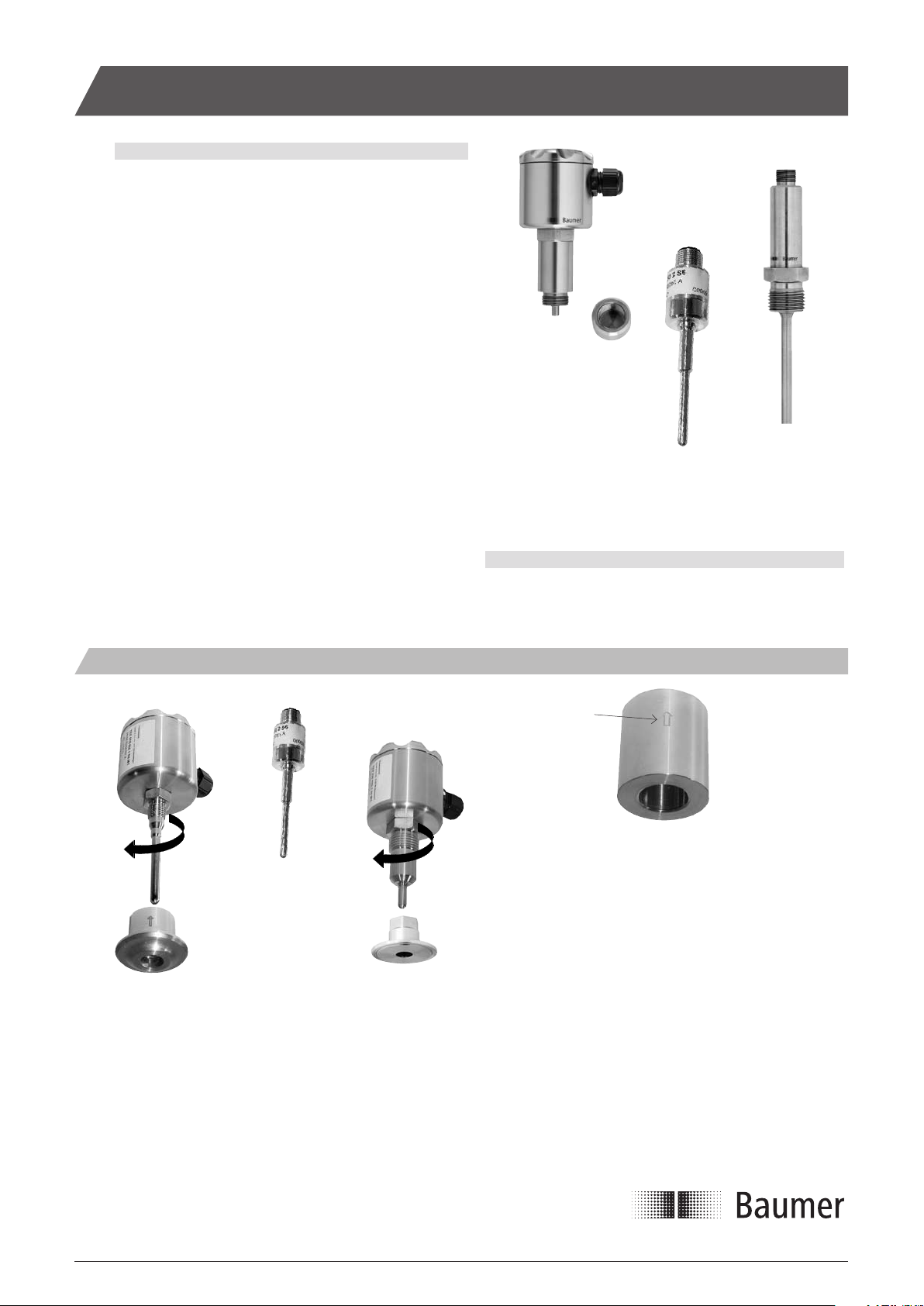
TE1
temperature-
sensor or
transmitter
TE2
temperature
sensor
TE2
temperature
transmitter
Mechanical Installation - Mounting Examples Mounting a Welding Part
M12 connection No thread G1/2A hygienic
Mark
The hygienic welding parts are easy to weld into tank walls and pipes.
10...20 Nm.
10...20 Nm.
PM031 CAM020
Use only the recommended sleeves or adapters. If other systems are
used, there is a severe risk of system malfunction or untight process
connections.
Do not use Teflon, elastomere or other types of gaskets for the
hygienic process connection featuring a conical seal.
The tightening torque is 10...20 Nm.
The mark or hole on the welding part indicates the final position of the
cable gland or M12 connector for a TE1/TE2 sensor.
We recommend to position the gland or plug downwards in order to
avoid water intrusion.
Check the tightness of the process connection. Make sure that the
cable gland or the M12 plug connector is properly screwed in.
Installation Manualwww.baumer.com/process
Page 1 Design and specifications subject to change without notice
Page 2
Page 2
Design and specifications subject to change without notice
Installation Manual
www.baumer.com/process
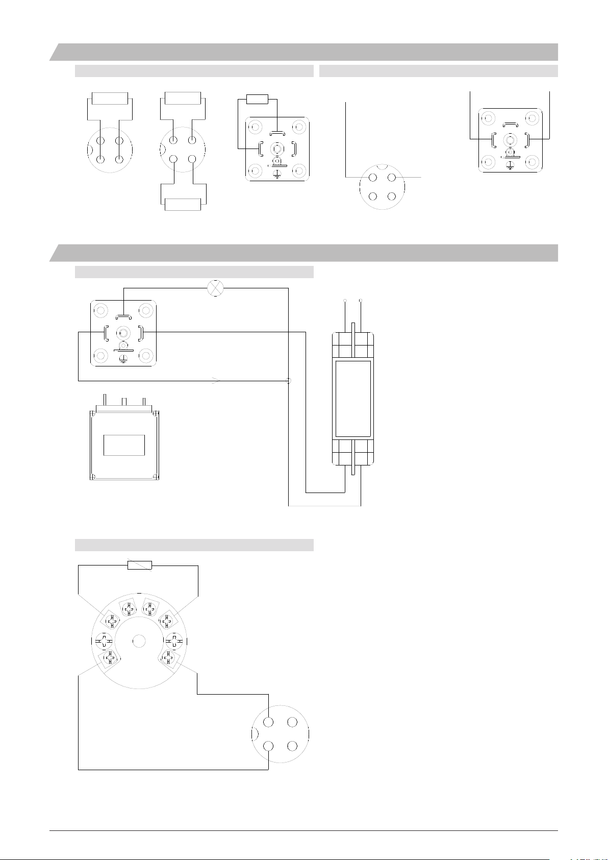
Electrical Installation
TE1/TE2 Temperature Sensor
Pt100
1 4
2 3
M12 Plug
Pt100
1 4
2 3
Pt100
Application Examples
TE2 with Integrated Transmitter and ZED601
3
1
2
Lamp
Pt100
2
Plug
DIN 43650-A
TE2 - Integrated Temperature Transmitter
- +
4...20 mA
3
1
230 Vac
3
Male plug
2
M12 Plug
4
1
Note:
The lamp is controlled by the open collector
output (PNP) from the ZED601 (optional).
4...20 mA
- +
3
2
Plug
DIN 43650-A
1
ZED601 display
mounted on a TE2
temperature transmitter
8888
TE1 with FlexTop Transmitter
RTD
4...20 mA
2
1
+ -
24 Vdc
Mounting example of a FlexTop 2201 temperature transmitter
Please refer to the relevant FlexTop manual in case a transmitter is
mounted.
2 1
4...20 mA (+)
4...20 mA (-)
1
2
Page 3

Page 3 Design and specifications subject to change without notice
Installation Manualwww.baumer.com/process
Configuration with FlexProgrammer
Note:
Disconnect loop supply before
connecting the FlexProgrammer
to the transmitter.
1
2
1
TE2 with integrated
transmitter
FlexTop
transmitter
2
2
FlexProgrammer 9701
Red clip
1
2
Black clip
2
Note: Ambient temperature range 0...50°C
1
Brown
1
1
Adapter cable for TE2 with integrated transmitter
White
2
In the following description the TE2 with an integrated transmitter and
the TE1 with a FlexTop temperature transmitter will be referred to as
“transmitter”.
The transmitter can be configured, using the 4...20 mA cable. The
maximum distance depends on the cable type, resistance and capacity. We recommend to use screened cables.
To be able to configure the transmitter with the FlexProgrammer the
dedicated software, FlexProgram, must be loaded on the PC.
The Flex-program has help menus for all functions.
Samples of Product Types
G1/2A (hygienic with a dedicated welding part)
During the configuration the new data are, by means of the FlexPro-
grammer, transferred from the PC to the transmitter, in which they are
stored in the internal memory.
The indication for a correct configuration sequence is:
TE1: The LED on the FlexTop lights up constantly.
TE2: The transmitter has no indication.
Note: During the first power-up after a configuration the power-on time
increases to approx. 10 sec.
M12 (hygienic with a dedicated welding part)
TE1x-4
TE2x-4 TE1x-5 TE2x-6TE2x-5
Page 4

Samples of Accessories
In case the TE1 is equipped with a FlexTop in-head transmitter or the
TE2 is with internal transmiiter the Flexprogrammer will be needed.
The FlexProgrammer 9701 is a dedicated tool to configure all
Baumer configurable products.
Type No. 9701-0001 complies:
FlexProgrammer interface unit
CD with the FlexProgram software and product drivers (DTM)
USB cable
Cable with 2 alligator clips
Mounting of 3A Approved Products
Max. ± 85°
1)
A full range of accessories for TE1 and TE2 can be found in the data
sheet ”Accessories”
4)
5)
2)
3)
Installation of 3A approved products:
1) Use only a 3A approved counter part.
2) The inspection hole should be visible and drained.
3) Mount the instrument in a self drained position.
4) Level the inner surface of the pipe with the counter part.
5) Weldings should be grinded to Ra= 0.8
Max. ± 175°
Refer to the data sheet “Accessories” for O-rings, gaskets and other
accessories.
The TE1x-7/8/9/A versions are approved by 3A providing it is installed
according to the guidelines given in the installation manual.
The 3A approved products fulfill the FDA demands and follow the
EHEDG guidelines regarding design, materials and finishing.
5850-006_EN/2011-10-10 This data sheet may only be reproduced in full.
www.baumer.com/process
Design and specifications subject to change without notice
Installation Manual
Page 4
 Loading...