

Page 1
Betriebsanleitung
Prozessanzeigen
TA1220
Operating
Instructions
Process displays
TA1220
Guide
utilisateur
Afficheur de process
TA1220
Inhalt Seite
Allgemeines /
1
Sicherheitshinweise 2
Beschreibung 4
2
Systembeschreibung 4
2.1
Anzeige 4
2.2
Grenzwertausgänge 4
2.3
Gerät anschliessen 5
3
Anschlussbelegung 5
3.1
Ein- und Ausgänge 6
3.2
Betriebsspannung anschl. 6
3.3
Anschlussbeispiele 7
3.4
Bedienerebene -
4
Programmierebene 8
Eingangskonfiguration 10
4.1
Anzeigenkonfiguration 10
4.2
Frequenzanzeige 10
4.2.1
Tachometer 10
4.2.2
Anzeigenskalierung 11
4.2.3
Anzeigenrefresh 12
4.3
Progr. Grenzwertausgänge 12
4.4
Schnittstelle 13
4.5
Grenzwerte 14
5
Code schützen 14
6
Technische Daten 15
7
Abmessungen 16
7. 1
Bestellbezeichnung 16
8
Baumer IVO GmbH & Co. KG
Contents Page
General /
Safety instructions 18
Description 20
System description 20
Display 20
Limit outputs 20
Connecting 21
Terminal assignment 21
Inputs and outputs 22
Voltage supply connection 22
Wiring examples 23
Operating mode -
Programming mode 24
Input configuration 26
Display configuration 26
Displaying frequency 26
Tachometer 26
Scaling of displayed value 27
Display refresh 28
Limit output configuration 28
Serial interface 29
Limit programming 30
Access programming 30
Technical data 31
Dimensions 32
Part number 32
Dauchinger Strasse 58-62 • DE-78056 Villingen-Schwenningen
Phone +49 7720 942-0 • Fax +49 7720 942-900
www.baumer.com • info.de@baumerivo.com
Subject to modifcation in technic & design.
Contenu Page
Consignes de
sécurité 34
Description 36
Caractéristiques principales 36
Plage d‘affichage 36
Sorties seuils 36
Raccorder l‘appareil 37
Raccordement des connecteur 37
Entrées / sorties 38
Alimentation 38
Exemples de raccordements 39
Mode consultation et
programmation 40
Configuration de l‘entrée 42
Configuration de l‘affichage 42
Mode fréquencemètre 42
Mode tachymètre 42
Mode plage d‘affichage 43
Rafraîchissement de l‘affich.
Configuration des seuils 44
Configuration liaison série 45
Programmation seuils 46
Verrouillage programmation
Caractéristiques techniques
Dimensions 48
Références de commande 48
44
47
06.13 • 171.55.338/1 • 81086761
Irrtum sowie Änderungen in
Technik und Design vorbehalten.
Sauf erreurs et sous réserve de
modifications techniques et design.
46
Page 2

TA1220
Allgemeines
Nachfolgend finden Sie die Erklärungen der verwendeten Symbole
dieser Betriebsanleitung.
Zeichenerklärung
Kursivschrift Zum schnellen Auffinden von Informationen sind wichtige Begriffe in
der linken Textspalte kursiv wiedergegeben.
Dieses Zeichen bedeutet ausführende Tätigkeiten.
● Dieses Zeichen steht für ergänzende technische Informationen.
Dieses Symbol steht vor jenen Textstellen, die besonders zu
beachten sind, damit der ordnungsgemässe Einsatz des Gerätes
gewährleistet ist.
Dieses Symbol steht vor jenen Textstellen, die zusätzliche wichtige
Informationen liefern.
1 Sicherheitshinweise
Allgemeine Hinweise
Das Gerät ist nach den anerkannten Regeln der Technik entwickelt
und gebaut worden. Das Gerät hat das Herstellerwerk betriebsbereit
und in sicherheitstechnisch einwandfreiem Zustand verlassen!
Um diesen Geräte-Status zu erhalten, ist es erforderlich, dass Sie
das Gerät
- bestimmungsgemäss,
- sicherheits- und gefahrenbewusst,
- unter Beachtung dieser Betriebsanleitung und insbesondere dieser
Sicherheitshinweise installieren/betreiben!
Stellen Sie sicher, dass das Personal die Betriebsanleitung, und hier
be sonders das Kapitel „Sicherheitshinweise“, gelesen und verstanden hat. Ergänzend zur Betriebsanleitung sind allgemeingültige gesetzliche und sonstige verbindliche Regelungen zur Unfallverhütung
und zum Umweltschutz zu beachten und sicherzustellen.
Diese Anleitung ist eine Ergänzung zu bereits vorhandenen Dokumentationen (Datenblatt, Montageanleitung, Katalog).
Bestimmungsgemässe Verwendung
Das Einsatzgebiet des Gerätes umfasst das Steuern und Überwachen von industriellen Prozessen in der Metall-, Holz-, Kunststoff-,
Papier-, Glas-, Textilindustrie u. ä.
Das Gerät darf nur
- in ordnungsgemäss eingebautem Zustand und den
- entsprechenden Angaben der Technischen Daten betrieben werden
2
www.baumer.com
Page 3

TA1220
Der Betrieb ausserhalb der angegebenen Beschreibungen/Parameter
ist nicht bestimmungsgemäss und kann in Verbindung mit den zu
steuernden/überwachenden Anlagen/Maschinen/Prozessen zu
- tödlichen Verletzungen,
- schweren Gesundheitsschäden,
- Sachschäden oder
- Schäden an den Geräten führen!
Die Überspannungen, denen das Gerät an den Anschlussklemmen
ausgesetzt wird, müssen auf den Wert der Überspannungskategorie II
(siehe Technische Daten) begrenzt sein!
Das Gerät darf nicht
- in explosionsgefährdeten Bereichen,
- als Medizingeräte,
- in Einsatzbereichen, die nach EN 61010 ausdrücklich genannt sind,
betrieben werden!
Wird das Gerät zur Steuerung/Überwachung von Maschinen oder
Prozessen benutzt, bei denen infolge Ausfall/Fehlfunktion oder Fehlbedienung des Gerätes
- eine lebensbedrohende Gefahr,
- gesundheitliche Risiken oder
- die Gefahr von Sach- oder Umweltschäden entstehen könnte(n),
dann müssen entsprechende Sicherheitsvorkehrungen getroffen
werden!
Manipulationen am Gerät können dessen Funktionssicherheit negativ
beeinflussen und somit Gefahren hervorrufen!
Führen Sie keine Reparaturen am Gerät durch! Schicken Sie defekte
Geräte an den Hersteller zurück!
Installation/Inbetriebnahme
Bei Veränderungen (einschliesslich des Betriebsverhaltens), die die
Sicherheit beeinträchtigen, ist das Gerät sofort ausser Betrieb zu setzen. Bei Installationsarbeiten an den Geräten ist die Stromversorgung unbedingt abzuschalten. Installationsarbeiten dürfen nur von
entsprechend ausgebildeten Fachkräften ausgeführt werden.
Nach korrekter Montage und Installation ist das Gerät betriebsbereit.
Wartung/Instandsetzung
Stromversorgung aller beteiligten Geräte unbedingt abschalten.
Wartungs- und Instandsetzungsarbeiten dürfen nur von entsprechend ausgebildeten Fachkräften ausgeführt werden.
Bei erfolgloser Störungssuche darf das Gerät nicht weiter eingesetzt
werden. Setzen Sie sich bitte mit dem Hersteller in Verbindung.
www.baumer.com
3
Page 4

TA1220
6(7
6(7
7$5(
352*
2 Beschreibung
2.1 Systembeschreibung
Der Tachometer eignet sich zu Darstellung von Frequenzen oder Geschwindigkeiten in industriellen Einsatzgebieten.
- Anzeigeneinheit 1/s, 1/min, 1/h programmierbar
- Eingang: NPN, PNP, Namur, TTL, 10...600 VAC
- Zwei Grenzwerte SET 1 und SET 2
- Sensorversorgung: 5 V, 8 V, 12 V
- Frequenz 0,01 Hz...7 kHz
- Periodendauermessung
- LED-Anzeige, 4-stellig
- DIN-Gehäuse 48 x 24 mm
- Schnittstelle RS485
2.2 Anzeige
4-stellige Anzeige
Fläche für Einheitenaufkleber
2.3 Grenzwertausgänge
Der Tachometer verfügt über zwei Relais-Grenzwertausgänge. Per
Programmierung HIGH oder LOW kann bestimmt werden, ob die
Ausgänge bei Anzeigewert ≥ oder ≤ Grenzwert aktiv geschaltet werden.
Die Ausgänge können mit einer Zeitverzögerung oder mit einer Hysterese programmiert werden.
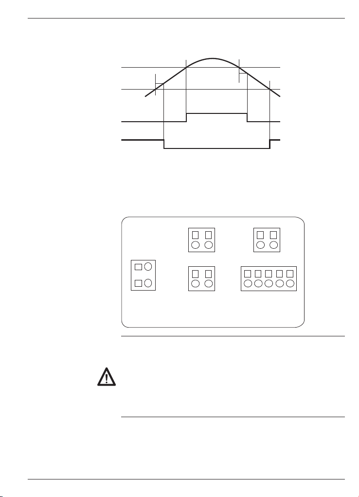
Zeitverzögerung der Grenzwertausgänge
Die Zeitverzögerung ist von 00 bis 99 s programmierbar.
Diese wirkt sowohl beim Ein- und beim Ausschalten der Grenzwertausgänge.
Grenzwert 1
Grenzwert 2
VerzögerungVerzögerung
Relais 1 =
HIGH
Relais 2 =
LOW
4
www.baumer.com
VerzögerungVerzögerung
Page 5
TA1220
Asymmetrische Hysterese
Die Hysterese wird in Anzeige-Einheiten von 0 bis 9999 programmiert. Diese wirkt nur beim Ausschalten der Grenzwertausgänge.
Grenzwert 1
Grenzwert 2
Hysterese
Relais 1 =
HIGH
Relais 2 =
LOW
Hysterese
3 Gerät anschliessen
In diesem Kapitel werden zuerst die Anschlussbelegung sowie einige
Anschlussbeispiele vorgestellt.
3.1 Anschlussbelegung
5HODLV$XVJDQJ6(75HODLV$XVJDQJ6(7
6HQVRU
&RPPRQ
,PSXOV
HLQJDQJ
QF
9$&
%HWULHEVVSDQQXQJ
56
7['5['
7['5['
(LQJlQJH
Litzenanschluss aus Gründen des Berührungsschutzes nach
EN61010 nur mittels Aderendhülsen mit Isolierstoffkappen. Vom
Werk unbelegte Anschlüsse nicht anderweitig belegen. Es wird
empfohlen, alle Sensor-Anschlussleitungen abzuschirmen und die
Abschirmung einseitig zu erden. Beidseitige Erdung wird empfohlen
bei HF-Störung und falls bei grösseren Entfernungen PotentialAusgleichsleitungen installiert sind. Die Sensor-Anschlussleitungen
sollen nicht im gleichen Kabelstrang mit der Netzversorgung und den
Ausgangs-Kontaktleitungen geführt werden.
www.baumer.com
5
Page 6
TA1220
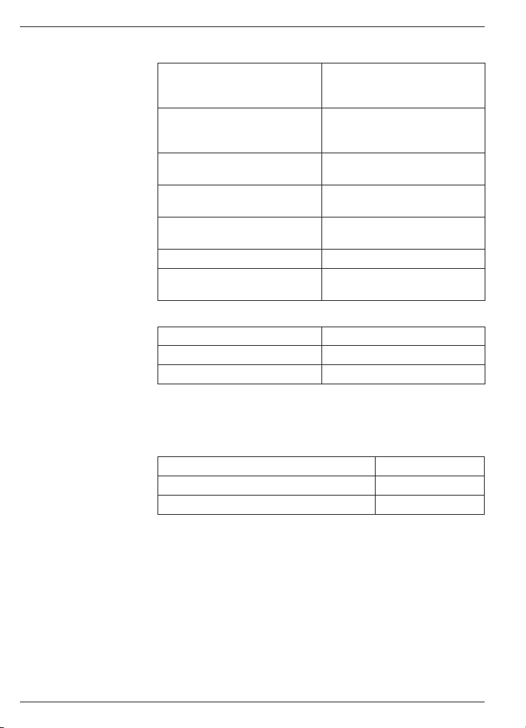
3.2 Ein- und Ausgänge
Impulseingang Spezifikation
PNP High-Pegel >2,6 V
NPN High-Pegel >2,6 V
TTL High-Pegel >2,6 V
NAMUR Ion <1 mA, Ioff >3 mA
Magnetsensor Vin >30 mVeff bei 60 Hz
Kontakt Eingangswiderstand 3,9 kΩ
Spannung 10...600 VAC Die Frequenz der Spannung
Relais-Ausgänge (SET 1, SET 2)
Schaltspannung max. 250 VAC / 110 VDC
Schaltstrom max. 1 A
Schaltleistung max. 150 VA / 30 W
3.3 Betriebsspannung anschliessen
Es stehen verschiedene Betriebsspannungen zur Verfügung.
Das Gerät muss netzseitig über die empfohlene externe Sicherung
betrieben werden.
Betriebsspannung externe Absicherung
85...265 VAC, (50/60 Hz) und 100...300 VDC
21...53 VAC, (50/60 Hz) und 10,5...70 VDC M 1 A
Low-Pegel <2,4 V
Eingangswiderstand 1,5 kΩ
Low-Pegel <2,4 V
Eingangswiderstand 3,9 kΩ
Low-Pegel <2,4 V
Eingangswiderstand 1,5 kΩ
Vin >300 mVeff bei 6 kHz
wird gemessen
M 100 mA
6
www.baumer.com
Page 7

Eingang 10...600 VAC
TA1220
3.4 Anschlussbeispiele
Kontakt- oder Magnet-
sensor
Namur Sensor
NPN oder PNP Sensor
TTL Sensor
3
4
Signal
+ 8 V Versorgung
Signal
- Common
+ Versorgung
Signal
- Common
+ Versorgung
www.baumer.com
7
Page 8
TA1220
4 Bedienerebene - Programmierebene
Bedienerebene
Das Gerät befindet sich nach dem Einschalten der Betriebsspannung
automatisch in der Bedienerebene. Es wird der aktuelle Wert angezeigt. Es können auch die MIN / MAX Werte aufgerufen werden.
MIN / MAX Funktion
Bei jeder Tastenbetätigung erscheinen nacheinander die Werte
MAX, MIN und der aktuelle Messwert. Der angezeigte Wert MAX
oder MIN kann durch 3 sek. Betätigung der Taste zurückgesetzt
werden. Bei einem Spannungsausfall werden die Werte MAX und
MIN nicht gespeichert.
Programmierebene
Der Programmiermodus erlaubt die vollständige Konfiguration der
Prozessanzeige. Er ist in 4 Module unterteilt:
- Konfiguration Eingangssignal
- Konfiguration der Anzeige
- Konfiguration der Grenzwertausgänge
- Konfiguration der seriellen Schnittstelle
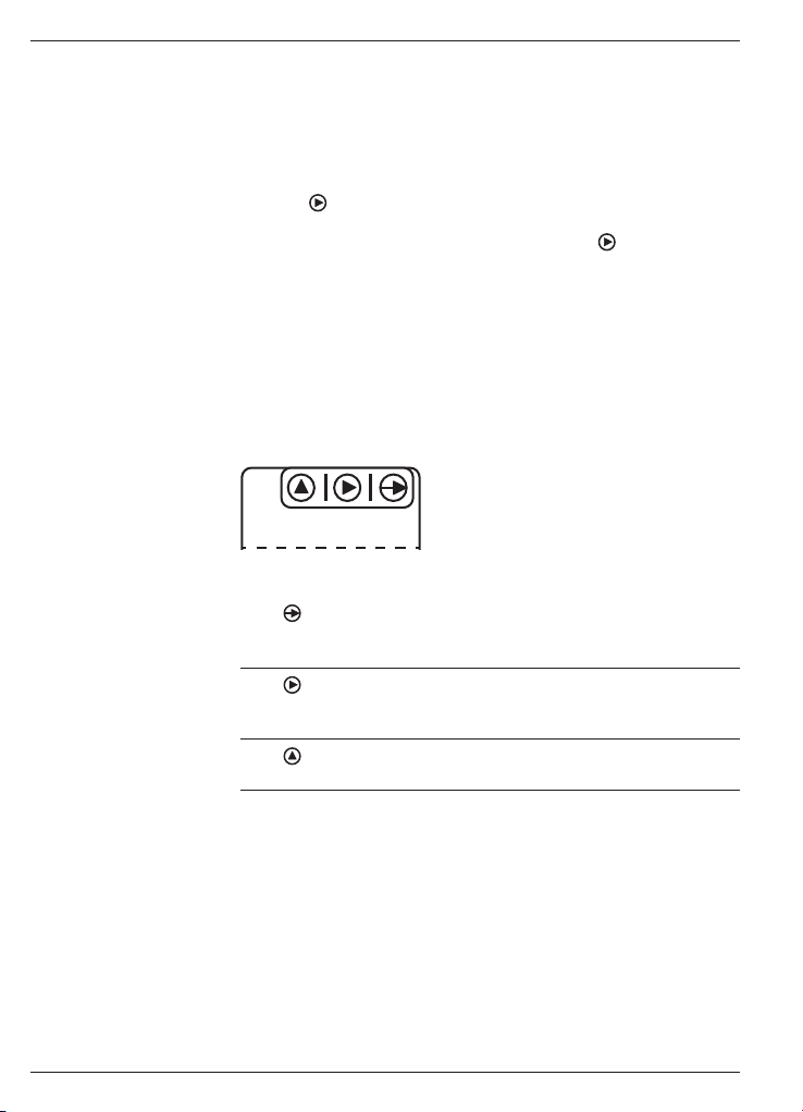
Tastatur
(Sicht von unten)
Tastenfunktion
Taste
Dient zum Einstieg in die Programmierebene und zur Auswahl der
Programmierzeile.
Taste
Dient zur Funktionsauswahl oder Dekadenauswahl in der Programmierzeile. Die jeweils angewählte Dekadenstelle blinkt.
Taste
Dient zum inkrementieren (hochzählen) der angewählte Dekade.
8
www.baumer.com
Page 9
TA1220
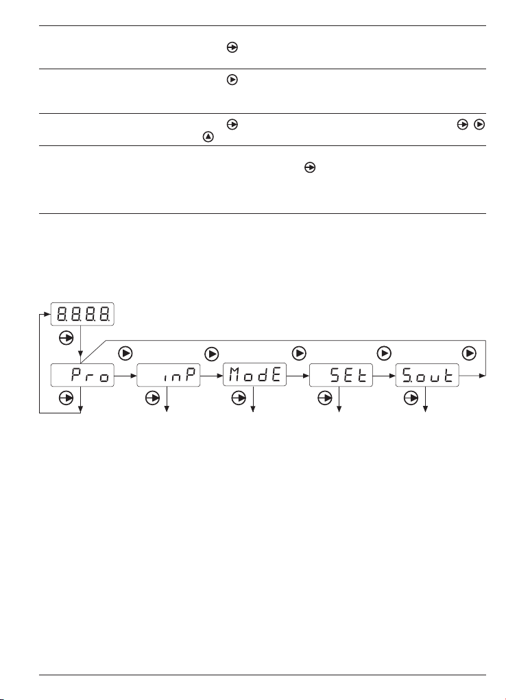
Programmiervorgang
1. Die Taste drücken, [Pro] wird angezeigt für den Einstieg in die
Programmierung, die LED PROG blinkt.
2. Mit Taste
das gewünschte Programmiermodul anwählen. Die
verschiedenen Module sind mit einer Kurzbezeichnung gekennzeichnet. (InP, dSP, Set, S.out).
3. Mit Taste
das ausgewählte Modul bestätigen und mittels ,
und Tasten die gewünschten Funktionen programmieren.
4. Wenn nötig die weiteren Module programmieren und den Programmiermodus mit Taste
verlassen, wenn wieder [Pro] in der
Anzeige steht. Der Programmiermodus wird dann automatisch
verlassen, [Stor] wird kurz angezeigt und die Programmierung
gespeichert.
5. Der Einstieg in die Programmierung kann in der Programmierebene gesperrt werden. Siehe Kapitel „Programmierung über Code
geschützt“. Die verschiedenen Programmierzeilen können dann
nur visualisiert aber nicht geändert werden. Beim Einstieg in die
Programmierebene erscheint dann [DAtA] anstelle von [Pro].
Überblick Konfigurationsmodelle
Einstieg/verlassen des
Programmiermodus
Konfiguration des
Eingangssignals
Konfiguration der
Anzeige/Messprinzip
Konfiguration der
Grenzwertausgänge
Das Modul S.out erscheint nur, wenn das Gerät mit der Option
„serielle Schnittstelle“ ausgestattet ist.
www.baumer.com
Konfiguration der
seriellen Schnittstelle
9
Page 10

TA1220
4.1 Eingangskonfiguration
Auswahl Eingangssignal
Spannungseingang 10...600 VAC
Magnetsensor
Namur Eingang
PNP Eingang
NPN Eingang
TTL Eingang
Kontakt Eingang (20 Hz max.)
Sensor Spannung (*)
12 V für Geber und Näherungsschalter
8 V für Namur Sensor
5 V TTL
(*) Diese Programmierzeile erscheint nicht bei Auswahl Eingangssignal -1-, -2-, -7- ; die Sensorspannung ist dann automatisch auf 5 V
eingestellt.
4.2 Anzeigenkonfiguration
Auswahl: Anzeige / Messprinzip Modus
Frequenzanzeige (4.2.1)
Tachometer (4.2.2)
Anzeige Skalierung (4.2.3)
Je nach Auswahl erscheint in den folgenden Programmierzeilen nur
das entsprechende Kapitel. Z.B. bei Auswahl FrEC erscheint nur das
Kapitel 4.2.1. Die Kapitel 4.2.2 und 4.2.3 erscheinen nicht mehr.
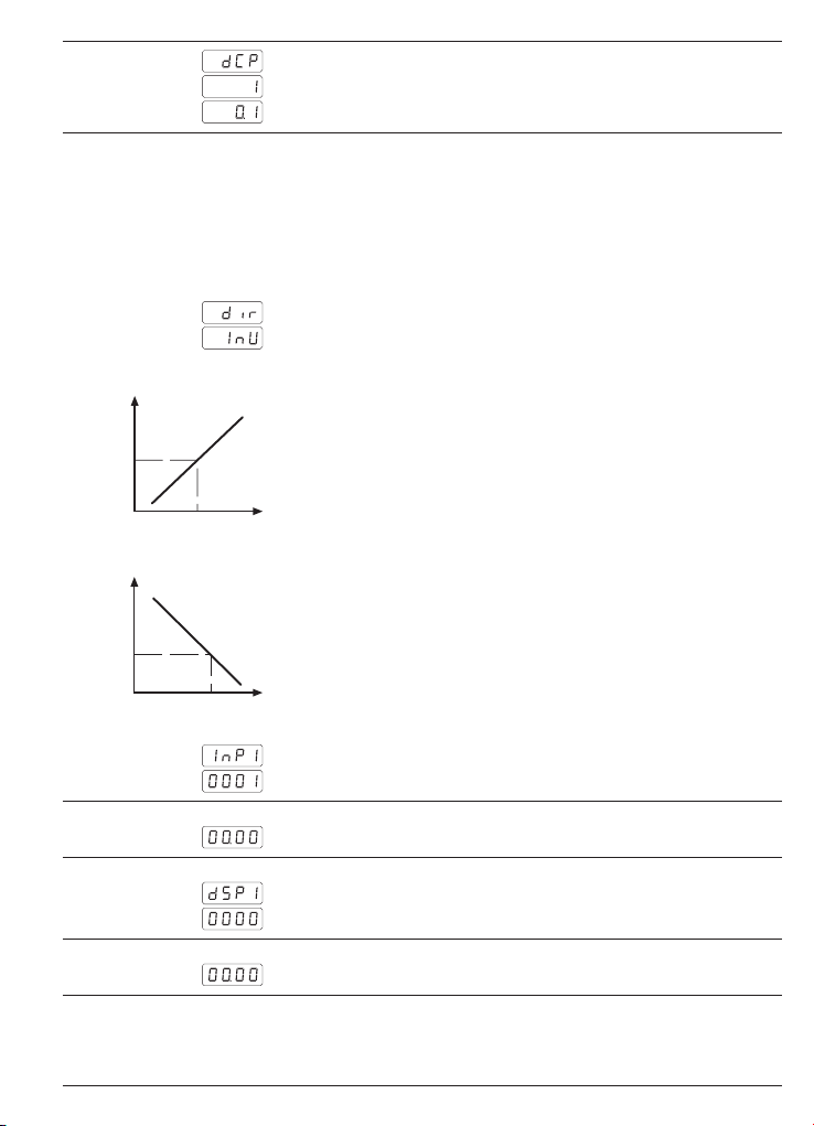
4.2.1 Frequenzanzeige
Die Eingangsfrequenz wird direkt in Hz angezeigt.
Dezimalpunkt
Kein Dezimalpunkt
0.1 Dezimalpunkt an der ersten Stelle
0.01 Dezimalpunkt an der zweiten Stelle.
4.2.2 Tachometer
Anzeige von Drehzahl oder Geschwindigkeit pro min.
Impulsbewertung
Es muss hier die Anzahl Impulse pro Anzeigeneinheit eingegeben
werden. (z.B. Impulse/Meter oder Impulse/Umdrehung…)
Zulässiger Bereich von 1 bis 9999.
Beispiel: Um die Geschwindigkeit in Umdrehungen/min anzuzeigen
(z.B. bei gelieferten 500 Impulse/Umdrehung) muss als Impulsbewertungsfaktor 500 eingegeben werden.
10
www.baumer.com
Page 11
TA1220
Dezimalpunkt
Kein Dezimalpunkt
Dezimalpunkt an der erste Stelle
4.2.3 Anzeigenskalierung (rAtE)
Es muss hier eine Eingangsfrequenz und der zugehörige Anzeigewert eingegeben werden. Das Gerät berechnet dann das Verhältnis
zwischen beiden. Der Anzeigewert ergibt sich dann als die Eingangsfrequenz x Verhältnis. Es kann zusätzlich gewählt werden zwischen
Anzeige proportional oder invers proportional zu Eingangsfrequenz.
Anzeige Verhalten
Direkt proportional zu Eingangsfrequenz
Invers proportional zu Eingangsfrequenz
Direkt proportional Der Anzeigewert steigt mit der Eingangsfrequenz.
Geeignet z.B. für Produktionsanzeige 1/h.
Anzeigewert
Frequenz
Invers proportional Der Anzeigewert sinkt wenn die Eingangsfrequenz steigt.
Geeignet z.B. für Anzeige der Durchlaufzeit eines Backofen.
Anzeigewert
Frequenz
Eingangsfrequenz
Eingabe der Eingangsfrequenz. Bereich von 1 bis 9999.
Dezimalpunkt Eingangsfrequenz
Auswahl Dezimalpunkt für die Frequenz Eingabe.
Anzeigenwert
Eingabe Anzeigenwert. Dieser Wert entspricht der unter InP 1 eingegebener Frequenz.
Dezimalpunkt Anzeige
Auswahl Dezimalpunkt für den Anzeigenwert.
www.baumer.com
11
Page 12
TA1220
Beispiel für eine direkt proportionale Anzeige:
Es soll die Produktion in Stück/Stunde einer Presse angezeigt werden. Bei jedem Hub werden 2 Teile produziert und dass im Rhythmus von 1 Hub/s. Ein Inkremental-Drehgeber ist mit dem Schwungrad verbunden und liefert 500 Impulse/Hub.
In einer Stunde werden so 2 (Teile) x 3600 (s) = 7200 Teile produziert.
Parametrier Werte:
Anzeige Verhalten = dır (Direkt proportional)
InP1 = 500
dSP1 = 7200
Beispiel für eine invers proportionale Anzeige:
Es soll die Backzeit oder Durchlaufzeit eines Tunnelofen angezeigt
werden. Ein Inkremental-Drehgeber ist mit der Antriebswelle des
Transportbandes verbunden und liefert 50 Impulse/Umdrehung. Bei
Nenngeschwindigkeit beträgt die Durchlaufzeit 75 s und die Antriebswelle dreht mit 300 Umdrehungen/min bzw. 5 Umdrehungen/s.
Die Impuls-Eingangsfrequenz ist dann 5 x 50 Impulse = 250 Impulse/s.
Parametrier Werte:
Anzeige Verhalten = InU (Invers proportional)
InP1 = 250
dSP1 = 75
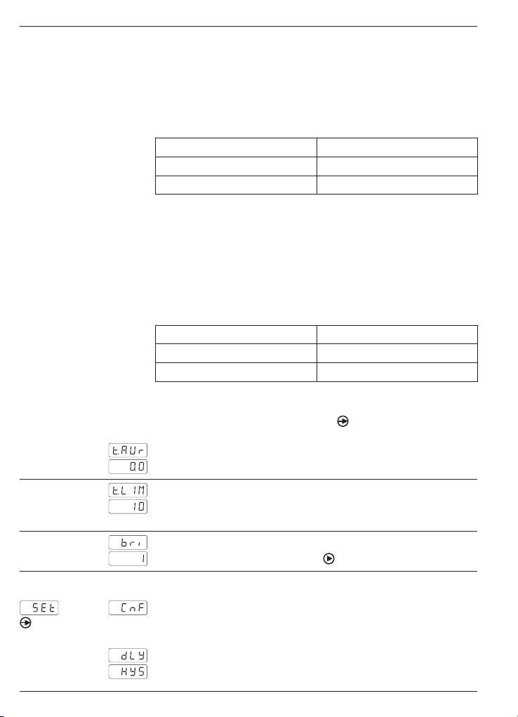
4.3 Anzeigenrefresh-Konfiguration
Für den Einstieg in dieses Modul Taste
gabe des letzten Parameters im Modul „Konfiguration Anzeige“.
Update Time (Anzeigenwiederholung)
Einstellbar von 0,1 bis 9,9 s.
5 s drücken nach der Ein-
Time out
Einstellbar von 1 bis 99 s.
Bei Stillstand erfolgt nach Ablauf dieser Zeit eine Nullstellung.
Anzeigehelligkeit
Programmierbar von 1 bis 4 mit der
4.4 Konfiguration der Grenzwertausgänge
12
Grenzwert Nr. 1 LED SET 1 leuchtet
Betriebsmodus
Zeitverzögerung
Hysterese
www.baumer.com
Taste.
Page 13
TA1220
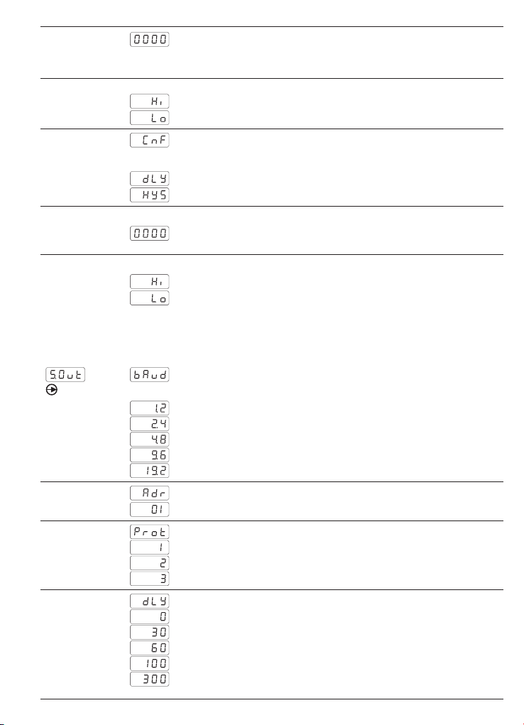
Verzögerung oder Hysterese Wert
Programmierung der Verzögerung (dLY) von 0 bis 99 s oder Hysterese (HYS) von 0 bis 9999 Anzeigeeinheiten.
Aktivierung Grenzwertausgang
HIGH = Aktiv bei Anzeigewert ≥ Grenzwert
LOW = Aktiv bei Anzeigewert ≤ Grenzwert
Grenzwert Nr. 2 LED SET 2 leuchtet
Betriebsmodus
Zeitverzögerung
Hysterese
Verzögerung oder Hysterese Wert
Programmierung der Verzögerung (dLY) von 0 bis 99 s oder Hysterese (HYS) von 0 bis 9999 Anzeigeeinheiten.
Aktivierung Grenzwertausgang
HIGH = Aktiv bei Anzeigewert ≥ Grenzwert
LOW = Aktiv bei Anzeigewert ≤ Grenzwert
Wenn ein Grenzwertausgang aktiv ist, leuchtet die entsprechende
LED SET 1 oder 2 dauernd im (dLY) Modus oder blinkt im (HYS) Modus.
4.5 Konfiguration der serielle Schnittstelle
Übertragungsgeschwindigkeit
1200 Baud
2400 Baud
4800 Baud
9600 Baud
19200 Baud
Geräteadresse
Programmierbar von 01 bis 99
Kommunikationsprotokoll
Protokoll ASCII
Protokoll ISO 1745
Protokoll MODBUS (RTU)
Reaktionszeit der Antwort
Ohne Verzögerung
Verzögerung 30 ms
Verzögerung 60 ms
Verzögerung 100 ms
Verzögerung 300 ms
www.baumer.com
13
Page 14
TA1220
5 Programmierung der Grenzwerte
Diese Programmierung ist unhabhängig von der Programmierung der
Konfigurationsmodule, und kann jederzeit durchgeführt werden.
Programmiervorgang
1. Taste
2. Mit Taste den ersten Grenzwert anwählen.
Grenzwert Nr. 1 LED SET 1 leuchtet.
3. Taste drücken um den Grenzwert Nr. 2 zu erreichen.
Grenzwert Nr. 2 LED SET 2 leuchtet.
4. Taste
drücken, [Pro] wird angezeigt für den Einstieg in die
Programmierung, die LED PROG blinkt.
Grenzwert Nr. 1 mit Tasten und ändern.
Grenzwert Nr. 2 mit Tasten und ändern.
drücken um beide Werte zu speichern und den Program-
miermodus zu verlassen.
6 Programmierebene über Code schützen
Die Programmierung kann gegen ungewünschte Änderungen durch
einen Code geschützt werden:
- entweder vollständig
wenn die Programmierung geschützt ist, hat man immer noch die
Möglichkeit die verschiedenen Konfigurationsmodule zu visualisieren aber nicht zu ändern. In diesem Fall wird [DAtA] anstelle von
[Pro] angezeigt wenn man in den Programmiermodus einsteigt.
- oder teilweise
durch selektieren der verschiedenen Konfigurationsmodule, die geschützt werden sollen. Auch hier hat man die Möglichkeit die verschiedenen Konfigurationsmodule zu visualisieren aber nicht zu ändern.
Code eingeben oder ändern
1. Taste
2. Mit Taste
3. Code ändern
Ja
Neuer Code eingeben, zwischen 0000 und 9999
4. Vollständige Verriegelung
Nein (Teilverriegelung)
Ja
Bei teilweiser Verriegelung kann man für die folgenden Konfigurationsmodule bestimmen ob die Programmierung geschützt oder
zugängig bleibt.
14
3 s drücken, [CodE] erscheint in der Anzeige und die
LED PROG blinkt.
und den Code eingeben. Der Default Wert nach
Auslieferung des Gerätes ist „0000“.
Nein
www.baumer.com
Page 15

Konfiguration Eingangssignal
Konfiguration der Anzeige/Messprinzip
Konfiguration Ausgang 1
Grenzwert 1
Konfiguration Ausgang 2
Grenzwert 2
Konfiguration serielle Schnittstelle
0:1:Programmierung zugängig
Programmierung geschützt
7 Technische Daten
Technische Daten - elektrisch
Betriebsspannung 21...53 VAC (50/60 Hz) oder
Leistungsaufnahme 5 W
Sensorversorgung 5 V, 8 V oder 12 V programmierbar /
Anzeige LED, 7-Segment Anzeige (mit 60Ein-
Stellenzahl 4-stellig
Ziffernhöhe 10 mm
Anzeigenbereich 9999 („OuE“ als overflow Anzeige)
Anzeigenrefresh 0,1...9,9 s (programmierbar)
Programmierbare Einheiten 1/h, 1/min, 1/s
Parameter Sensorlogik, Dezimalpunkt,
Messprinzip Periodendauermessung
Signaleingänge NPN, PNP, Namur, TTL,10...600 VAC
Zählfrequenz 0,01 Hz...7 kHz
Skalierungsfaktor 1... 9999
Datenspeicherung >10 Jahre im EEPROM
Ausgänge Relais
Schnittstelle RS485
Auslegung Schutzklasse II
DIN EN 61010-1 Überspannungskategorie II
Störaussendung DIN EN 61000-6-3
Störfestigkeit DIN EN 61000-6-2
10,5...70 VDC
85...265 VAC (50/60 Hz) oder
100...300 VDC
60 mA
heitenaufkleber für Front)
Sensorspannung, Impulsbewertung
Verzögerung oder Hysterese für
Relaisausgänge
oder Kontakt programmierbar
(20 Hz bei Kontakteingang)
Öffner oder Schliesser, programmierbar
Verschmutzungsgrad 2
TA1220
www.baumer.com
15
Page 16

TA1220
6(7
6(7
7$5(
352*
Technische Daten - mechanisch
Umgebungstemperatur -10...+60 °C
Lagertemperatur -25...+85 °C
Relative Luftfeuchte 95 % nicht betauend
Anschluss Federkraftklemme steckbar
Aderquerschnitt 1 mm² (Raster 2,54)
2,5 mm
2
(Raster 7,62)
Schutzart DIN EN 60529 IP 65 (frontseitig)
Bedienung / Tastatur 3 Kurzhubtasten unter Frontrahmen
Gehäuseart Einbaugehäuse
Abmessungen B x H x L 48 x 24 x 136 mm
Montageart Frontplatteneinbau mit Spannrahmen
Werkstoffe Gehäuse: Polycarbonat UL 94V-0
Masse ca. 100 g
7. 1 Abmessungen
TA1220 - ohne Spannrahmen
TA1220 - Spannrahmenmontage
8 Bestellbezeichnung
TA1220. 1 AX01
0 Ohne Schnittstelle
1 RS485
16
www.baumer.com
Betriebsspannung
4 85...265 VAC und 100...300 VDC
5 21...53 VAC und 10,5...70 VDC
Schnittstelle
Page 17

Operating
Instructions
Process displays
TA1220
Contents Page
General / Safety instructions 18
1
Description 20
2
System description 20
2.1
Display 20
2.2
Limit outputs 20
2.3
Connecting 21
3
Terminal assignment 21
3.1
Inputs and outputs 22
3.2
Voltage supply connection 22
3.3
Wiring examples 23
3.4
Operating mode - Programming mode 24
4
Input configuration 26
4.1
Display configuration 26
4.2
Displaying
4.2.1
Tachometer 26
4.2.2
Scaling of displayed value 27
4.2.3
Display refresh 28
4.3
Limit output configuration 28
4.4
Serial interface 29
4.5
Limit programming 30
5
Access programming 30
6
Technical data 31
7
Dimensions 32
7. 1
Part number 32
8
frequency 26
TA1220
www.baumer.com
17
Page 18

TA1220
General Information
In the following you will find the explanations of the symbols used
in this operating manual.
Explanation of symbols ➜ This symbol indicates activities to be carried out.
● This symbol indicates supplementary technical information.
This symbol is located before texts to which particular attention is to
be paid to ensure proper use of the product.
This symbol is located before texts that provide important additional
information.
Italics To help you quickly locate information, important terms are printed in
italics in the left text column.
1 Safety instructions
General information
The products has been developed and built in accordance with the
recognized rules of technology. The units have left the manufacturing
plant ready to operate and in safe condition.
To keep the units in this condition, it is necessary that the units be
- installed and operated
- properly,
- in a safety and hazard-conscious manner,
under observance of this operating manual and in particular of these
safety precautions!
Make sure that the personnel has read and understood the operating
manual, and in particular the „Safety Instructions“ chapter.
In addition to the operating manual, the generally applicable legal and
other binding regulations for accident prevention and environmental
protection must be observed and ensured.
This manual is intended as a supplement to already existing documentation (catalogues, data sheets or assembly instructions).
Proper use
The application of the units consists of controlling and monitoring
industrial processes in the metal, wood, plastics, paper, glass and
textile industry etc.
The units may only be operated
- in the properly installed state and
- in accordance with the specifications of the technical data
18
www.baumer.com
Page 19

TA1220
Operation not covered by the specified descriptions/parameters is
improper and can lead to
- fatal injuries,
- serious damage to health,
- property damage or
- damage to the units
in conjunction with the systems/machines/processes to be
controlled/monitored!
The overvoltages to which the units are subjected at the connection
terminals must be limited to the value of the overvoltage category II
(see Technical data)!
The units may not be operated
- in hazardous areas,
- as medical units,
- in applications expressly named in EN 61010!
If the units are used to control/monitor machines or processes with
which, as the result of a failure/malfunction or incorrect operation of
the units
- a life-threatening danger,
- health risks or
- a danger of property or environmental damage
could result, then appropriate safety precautions must be taken!
Tampering with the units can have a negative affect on their operating safety, resulting in dangers!
Do not make repairs on the units! Return defective units to the manufacturer!
Installation/commissioning
In case of changes (including in the operating behavior) that impair
safety, shut-down the units immediately. During installation work on
the units, the power supply must always be disconnected. Installation work may only be carried out by appropriately trained experts.
Maintenance/repairs
Always disconnect the power supply of all units involved. Maintenance and repair work may only be carried out by appropriately
trained experts.
If troubleshooting is unsuccessful, do not continue to use the units.
Please contact the manufacturer in this case.
www.baumer.com
19
Page 20

TA1220
6(7
6(7
7$5(
352*
2 Description
2.1 System description
Intended use of the tachometer: Displaying frequencies and speed
in industrial applications.
- Reading programmable as 1/s, 1/min, 1/h
- Input: NPN, PNP, Namur, TTL, 10…600 VAC
- Two limits SET 1 and SET 2
- Sensor supply 5 V, 8 V, 12 V
- Frequency 0.01 Hz…7 kHz
- Period duration measurement
- LED display, 4-digits
- DIN housing 48 x 24 mm
- Interface RS485
2.2 Display
4 digits
Sticker to indicate measuring unit
2.3 Limit outputs
The device provides two relay limit outputs. Output trigger either at
≥ displayed value or ≤ limit is defined by HIGH or LOW configuration.
The outputs can be configured as time delay or hysteresis.
Limit outputs as time delay
Time delay parameterization is within the range from 00 to 99 s and
will be effective both at limit output power on and off.
Limit 1
Limit 2
DelayDelay
Relay 1 =
HIGH
Relay 2 =
LOW
20
www.baumer.com
DelayDelay
Page 21

TA1220
Asymmetrical hysteresis
Hysteresis is configured in display units from 0 to 9999 and only
effective at limit output power off.
Limit 1
Limit 2
Hysteresis
Relay 1 =
HIGH
Relay 2 =
LOW
Hysteresis
3 Connection
This chapter is about terminal assignment and will present some
swiring examples.
3.1 Terminal assignment
5HOD\RXWSXW6(75HOD\RXWSXW6(7
6HQVRU
&RPPRQ
LQSXW
,PSXOVH
QF
9$&
6XSSO\YROWDJH
56
7['5['
7['5['
,QSXWV
Litz contact only by means of connector sleeves with insulating
enclosures for reasons of shock protection according to EN 61010.
Do not otherwise assign contacts that have been left unassigned ex
factory. We recommend to screen all sensor terminal leads and to
ground the shield on one side. Shields on both sides are recommended in case of RF interference or in case of equipotential bonding
over long distances. The sensor leads should not be in the same
phase winding as the mains supply and the output contact leads.
www.baumer.com
21
Page 22

TA1220
3.2 Inputs and outputs
Signal input Specification
PNP High level >2.6 V
NPN High level >2.6 V
TTL High level >2.6 V
NAMUR Ion <1 mA, Ioff >3 mA
Magnetic sensor Vin >30 mVeff at 60 Hz
Contact Input resistance 3.9 kΩ
Voltage 10...600 VAC Measuring the frequency of the
Relay outputs (SET 1, SET 2)
Switching voltage max. 250 VAC / 110 VDC
Switching current max. 1 A
Switching performance max. 150 VA / 30 W
3.3 Voltage supply connection
There are several options for operation supply. Power supply must
be fed in via the recommended external fuse.
Operating voltage External protection
85...265 VAC, (50/60 Hz) and 100...300 VDC
21...53 VAC, (50/60 Hz) and 10.5...70 VDC M 1 A
Low level <2.4 V
Input resistance 1.5 kΩ
Low level <2.4 V
Input resistance 3.9 kΩ
Low level <2.4 V
Input resistance 1.5 kΩ
Vin >300 mVeff at 6 kHz
voltage
M 100 mA
22
www.baumer.com
Page 23

Input 10...600 VAC
TA1220
3.4 Wiring examples
Contact- or Magnetic
sensor
Namur sensor
NPN or PNP sensor
TTL sensor
3
4
Signal
+ 8 V Supply
Signal
- Common
+ Supply
Signal
- Common
+ Supply
www.baumer.com
23
Page 24

TA1220
4 Operating mode – programming mode
Operating mode
After power-on the device is in operator mode and indicates the current value. MIN / MAX functions are enabled.
MIN / MAX function
Every key operation will provide the MAX, MIN and current
measured value one after the other. To reset MAX or MIN, press and
hold the key for 3 seconds. MAX and MIN will not be retained in
the event of power failure.
Programming mode
Overall configuration of the process display is in programming mode
providing 4 modules:
- Configuration input signal
- Configuration of the display
- Configuration of limit outputs
- Configuration of the serial interface
Keypad
(view from below)
Key functions
Key
Access programming level and select programming line.
Key
Select functionality or decade in the programming line. The selected
digit is flashing.
Key
For incrementing of selected decades.
24
www.baumer.com
Page 25

TA1220
Programming
1. Press to access programming mode. [Pro] appears in the
display, LED PROG starts flashing.
2. Press
to select the required programming module. Each modu-
le comes with its individual abbreviation (InP, dSP, Set, S.out).
3. Proceed with line parameterization using keys
, and .
4. Where required, proceed alike for parameterization in the remaining modules. Once [Pro] has appeared in the display again, press
to exit programming mode. [Stor] appears briefly to indicate
parameter saving.
5. Programming mode also provides optional programming lock (see
chapter „Programming lock by authorization code“). In this case,
each programming line is visible but secured by parameter lock
which will be signaled by [DAtA] appearing in the display instead
of [Pro].
Overview on configuration module
Access/exit
programming mode
Configuration
input signal
Display configuration/
measuring principle
Configuration
of limit outputs
Module S.out is only available if the device provides the optional
„serial interface“.
www.baumer.com
Configuration
of the serial interface
25
Page 26

TA1220
4.1 Input configuration
Selecting the input signal
Voltag input 10...600 VAC
Magnetic sensor
Namur
PNP
NPN
TTL
Contact input (20 Hz max.)
Sensor supply (*)
12 V for encoder and proximity switch
8 V for Namur Sensor
5 V TTL
(*) This programming line is not available at input signal selection
-1-, -2-, -7- ; In this case sensor supply is predefined to be 5 V.
4.2 Display configuration
Selection: Display / mode of measuring principle
Frequency display (4.2.1)
Tachometer (4.2.2)
Display scaling (4.2.3)
Depending on the selection, subsequent programming lines will
only provide the related chapter. Example: Selection FrEC will only
provide chapter 4.2.1 and no longer 4.2.2 and 4.2.3
4.2.1 Displaying frequency
Input frequency is in Hz.
Decimal point
No decimal point
0.1 Decimal point at first digit
0.01 Decimal point at second digit.
4.2.2 Tachometer
Indication of rpm or speed per minute.
Pulse evaluation
Required input of pulse number per displayed unit (e.g. pulses/meter
or pulses/revolution….)
Permitted range: 1 to 9999.
Example: To indicate speed as rpm with 500 ppr, enter pulse evaluation factor 500.
26
www.baumer.com
Page 27

TA1220
Decimal point
No decimal point
Decimal point at first digit
4.2.3 Scaling of displayed value (rAtE)
Here, the displayed value is to be assigned an input frequency to calculate the ratio between these two. The displayed value is calculated
by input frequency multiplied by ratio with two selection options:
Direct proportional to input frequency and inverted proportional to input frequency.
Display behavior
Direct proportional to input frequency
Inverted proportional to input frequency
Direct proportional Displayed value will be increasing with the input frequency.
Application example: Displaying the production time 1/h.
Displayvalue
Frequency
Inverted proportional Displayed value will be descending with increasing input frequency.
Application example: Displaying the oven processing time.
Displayvalue
Frequency
Input frequency
Enter the input frequency within the range 1 to 9999.
Decimal point in the input frequency
Select decimal point in the input frequency.
Displayed value
Enter displayed value which corresponds to the frequency parameter
in InP 1.
Decimal point in the displayed value
Select decimal point position in the displayed value.
www.baumer.com
27
Page 28

TA1220
Example of direct proportional display configuration:
Required is the production output in piece quantity per hour of a
press. Every stroke will produce 2 pieces in the rhythm of 1 stroke /
second. An incremental encoder attached to a flywheel provides 500
pulses per stroke.
Consequently, output per hour: 2 pieces x 3600 seconds = 7200 parts.
Parameterization:
Display behavior = dır (direct proportional)
InP1 = 500
dSP1 = 7200
Example of inverted proportional display configuration:
Required is the processing time of a tunnel baking oven. An incremental encoder attached to the drive shaft of the conveyor belt provides 50 pulses/revolution. Processing time at nominal speed is 75 s
at a drive shaft rotation speed of 300 rpm which means 5 revolutions
per second.
Analog to this, pulse input frequency is 5 x 50 pulses = 250 pulses/s.
Parameterization:
Display behavior = InU (inverted proportional)
InP1 = 250
dSP1 = 75
4.3 Display refresh configuration
After last parameter input in „Display configuration“ press key
and hold for 5 s to access the display refresh configuration.
Update Time
Configurable from 0.1 to 9.9 s.
Time out
Configurable from 01 to 99 s.
In the event of downtime, there will only be a reset operation once
this time period has expired.
Intensity parameter
Configurable from 1 to 4 by
4.4 Limit output configuration
28
Limit 1 LED SET1 lights up
Operating mode
Time delay
Hysteresis
www.baumer.com
key.
Page 29

TA1220
Time delay or hysteresis
Configuration of time delay (dLY) from 0 to 99 s or hysteresis (HYS)
from 0 to 9999 displayed units.
Activation of limit output
HIGH = enabled if displayed value ≥ limit value
LOW = enabled if displayed value ≤ limit value
Limit 2 LED SET 2 lights up
Operating mode
Time delay
Hysteresis
Time delay or hysteresis
Configuration of time delay (dLY) from 0 to 99 s or hysteresis (HYS)
from 0 to 9999 displayed units.
Activation of limit output
HIGH = enabled if displayed value ≥ limit value
LOW = enabled if displayed value ≤ limit value
An active limit output is signaled by the related LED SET 1 or 2 lit up
continuously in (dLY) mode or flashing in (HYS) mode.
4.5 Serial interface configuration
Transmission speed
1200 baud
2400 baud
4800 baud
9600 baud
19200 baud
Device address
Programmable from 01 to 99
Communication protocol
Protocol ASCII
Protocol ISO 1745
Protocol MODBUS (RTU)
Response reaction time
No delay
Delay 30 ms
Delay 60 ms
Delay 100 ms
Delay 300 ms
www.baumer.com
29
Page 30

TA1220
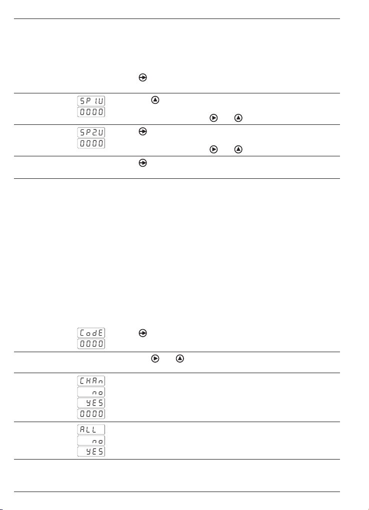
5 Limit programming
Limit programming does not relate to module configuration and can
be performed at all times.
How to proceed:
1. Press
2. Select first limit using key .
Limit 1 LED SET 1 lights up.
3. Press to access limit 2.
Limit 2 LED SET 2 lights up.
4. Press
, [Pro] appears in the display to signal access to program-
ming mode. LED PROG is flashing.
Press keys and to change limit 1.
Press keys and to change limit 2.
to save both limits and to exit programming mode.
6 Programming lock by authorization code
Parameterization can be locked by code against unauthorized alteration:
- either totally
With overall programming lock the individual configuration modules
will be provided but do not enable parameter changes, which is
indicated by [DAtA] appearing in the display instead of [Pro] when
accessing programming mode.
- or in part
by selecting the configuration modules to be protected. Here as well,
the modules remain visible but do not allow for parameter changes.
Enter or change code
1. Press key
and LED PROG lights up.
2. Enter code using key
„0000“.
3. Change code
No
Yes
Enter new code within the range of 0000 and 9999
4. Total lock
No (partial lock)
Yes
Partial lock allows for selection of the following configuration modules to be protected by code or not.
30
and hold for 3 seconds. [CodE] appears in the display
and . Default code at delivery is
www.baumer.com
Page 31

Configuration of input signal
Display configuration/measuring principle
Configuration output 1
Limit 1
Configuration output 2
Limit 2
Configuration of serial interface
0:1:programming enabled
programming disabled
7 Technical data
Technical data - electrical ratings
Voltage supply 21...53 VAC (50/60 Hz) or
Power consumption 5 W
Sensor supply 5 V, 8 V or 12 V
Display LED, 7-segment display (with 60 unit
Number of digits 4-digits
Digit height 10 mm
Display range 9999 („OuE“ to signal overflow)
Display refresh 0.1... 9.9 s (programmable)
Programmable Measuring units 1/h, 1/min, 1/s
parameters Sensor logic
Measuring principle Period duration measurement
Signal inputs Programmable as NPN, PNP, Namur,
Counting frequency 0.01 Hz...7 kHz (20 Hz if contact input)
Data memory >10 Jahre in EEPROM
Outputs relay
Interface RS485
Standard Protection class II
DIN EN 61010-1 Overvoltage category II
Emitted interference DIN EN 61000-6-3
Interference immunity DIN EN 61000-6-2
10.5...70 VDC
85...265 VAC (50/60 Hz) or
100...300 VDC
programmable/60 mA
stickers for front)
Decimal point
Sensor supply
Impulse evaluation
Relay outputs with time delay or
hysteresis
TTL, 10...600 VAC or contact
Normally open or closed, programmable
Pollution degree 2
TA1220
www.baumer.com
31
Page 32

TA1220
6(7
6(7
7$5(
352*
Technical data - mechanical design
Ambient temperature -10...+60 °C
Storing temperature -25...+85 °C
Relative humidity 95 % non-condensing
Connection Spring-loaded terminal connector,
detachable
Core cross-section 1 mm² (grid 2.54)
2.5 mm
2
(grid 7.62)
Protection DIN EN 60529 IP 65 (face)
Operation / keypad 3 softkeys below bezel
Housing type Built-in housing
Dimensions W x H x L 48 x 24 x 136 mm
Mounting Front panel installation by clip frame
Material Housing: Polycarbonate, UL 94V-0
Weight approx. 100 g
7. 1 Dimensions
TA1220 - without clip frame
TA1220 - clip frame mounting
8 Part number
TA1220. 1 AX01
0 Without interface
1 RS485
32
www.baumer.com
Voltage supply
4 85...265 VAC and 100...300 VDC
5 21...53 VAC and 10.5...70 VDC
Interface
Page 33

Guide
utilisateur
Afficheur de process
TA1220
Contenu Page
Consignes de sécurité 34
1
Description 36
2
Caractéristiques principales 36
2.1
Plage d‘affichage 36
2.2
Sorties seuils 36
2.3
Raccorder l‘appareil 37
3
Raccordement des connecteur 37
3.1
Entrées / sorties 38
3.2
Alimentation 38
3.3
Exemples de raccordements 39
3.4
Mode consultation et programmation 40
4
Configuration de l‘entrée 42
4.1
Configuration de l‘affichage 42
4.2
Mode fréquencemètre 42
4.2.1
Mode tachymètre 42
4.2.2
Mode plage d‘affichage 43
4.2.3
4.3
Rafraîchissement de l‘affichage
4.4
Configuration des seuils 44
4.5
Configuration liaison série 45
5
Programmation seuils 46
6
Verrouillage programmation
7
Caractéristiques techniques
7. 1
Dimensions 48
8
Références de commande 48
44
47
TA1220
46
www.baumer.com
33
Page 34

TA1220
Généralités
Ci-dessous, vous trouverez des explications sur les symboles utilisés
dans ce guide utilisateur.
Explications symboles
de réaliser une action spécifique.
Ecriture en italique Afin de trouver rapidement certaines informations, les mots clés
sont écrits en italique dans la colonne de gauche.
En face de ce symbole on trouvera des informations permettant
● En face de ce symbole on trouvera des informations techniques
complémentaires.
Ce symbole se trouve devant des informations qu‘il faut observer
tout particulièrement pour garantir une mise en service et un fonctionnement dans les règles de l‘art.
Ce symbole est placé devant des textes fournissant des informations
complémentaires.
1 Consignes de sécurité
Consignes générales
Cet appareil a été développé et fabriqué selon les normes et
prescriptions vigueur. L‘appareil a quitté l‘usine de production prêt à
fonctionner et en parfait état technique vis à vis de la sécurité!
Afin de conserver cet état, il est indispensable d‘installer et d‘utiliser
l‘appareil:
- conformément aux prescriptions
- en étant informé sur les règles de sécurité et les risques
- en respectant ce guide utilisateur et particulièrement les consignes
de sécurité qu‘il contient.
Assurez-vous que le personnel a lu et compris le guide utilisateur et
particulièrement le chapitre „Consignes de sécurité“. Il faut également observer et respecter les règles légales et contractuelles en
vigueur concernant la sécurité des personnes et la protection de
l‘environnement.
Conformité d‘utilisation
Le domaine d‘utilisation de l‘appareil correspond au contrôle et
commande de process industriels dans, entre autres, l‘industrie du
métal, du bois, du plastique, du papier, du verre, du textile...
L‘appareil ne doit être mis en service qu‘après avoir respectés:
- les règles de montage et d‘installations
- les indications et caractéristiques techniques
34
www.baumer.com
Page 35

TA1220
La non observation des paramètres, descriptions et prescriptions
peut conduire au niveau des installations, machines ou process à
piloter à:
- des blessures mortelles
- de graves dommages pour la santé
- des dommages matériels
- des dommages sur l‘appareil
Les surtensions auxquelles l‘appareil est soumis au niveau des
bornes de raccordement doivent être limitées à la catégorie II de surtension (Cf. caractéristiques techniques)!
- L‘appareil ne peut pas être utilisé:
- dans les secteurs à risque d‘explosion
- comme appareil médical
- dans les domaines d‘utilisations expressément nommés dans la
norme EN 61010!
Si l‘appareil est utilisé pour la commande ou le contrôle d‘une
machine ou d‘une installation pour laquelle une panne, une erreur de
manipulation de l‘appareil peut produire:
- un risque mortel
- des risques pour la santé
- des risques de dommages matériels ou environnementaux
alors il faut prendre des mesures de sécurité correspondantes!
Des interventions dans l‘appareil peuvent avoir un effet négatif sur la
sécurité de fonctionnement, et par conséquent, être dangereuses.
N‘effectuez aucune réparation sur l‘appareil! Retournez l‘appareil défectueux au constructeur!
Installation / Mise en service
Suite à des modifications ou changement de comportement qui influencent la sécurité, il y a lieu de mettre l‘appareil immédiatement
hors service. Lors des travaux d‘installation de l‘appareil, il faut impérativement couper l‘alimentation. Les travaux d‘installation ne doivent être réalisés que par du personnel qualifié. L‘appareil ne doit
être mis en service qu‘après montage et installation corrects.
Entretien / Maintenance
Couper impérativement l‘alimentation de l‘ensemble des appareils
de l‘installation. Les travaux d‘entretien et de maintenance ne doivent être effectués que par du personnel qualifié. Si la recherche
du dis-fonctionnement reste infructueuse, il ne faut pas remettre
l‘appareil en service. Dans ce cas veuillez contacter le constructeur.
www.baumer.com
35
Page 36

TA1220
6(7
6(7
7$5(
352*
2 Description
2.1 Caractéristiques principales
Le tachymètre est destiné à afficher une fréquence ou une vitesse
dans un environnement industriel.
- Unité d’affichage 1/h, 1/min, 1/s programmable
- Entrée: NPN, PNP, Namur, TTL, 10…600 VAC
- Deux seuils SET1 / SET2
- Alimentation capteur 5 V, 8 V, 12 V
- Fréquence 0,01 Hz…7 kHz
- Mesure de la période
- Affichage LED, 4 digits
- Boîtier DIN 48 x 24 mm
- Liaison série RS485
2.2 Affichage
Afficheur 4 digits
Emplacement étiquette d‘unités autocollantes
2.3 Sorties seuils
L’indicateur dispose de 2 seuils avec sorties relais. L’activation des
sorties est programmable en mode HIGH, c’est-à-dire lorsque la valeur affichée passe le seuil dans le sens croissant ou en mode LOW,
c’est-à-dire lorsque la valeur affichée passe le seuil dans le sens décroissant. Les seuils peuvent être programmés avec un retard temporisé ou une hystérésis.
Action retardée par temporisation
Le retard temporisé agit de part et d’autre du seuil quand la valeur
d’affichage passe par celui-ci dans le sens croissant ou décroissant.
Ce retard est programmable en secondes de 0 à 99.
Seuil 1
Seuil 2
RetardRetard
Relais 1 =
HIGH
Relais 2 =
LOW
36
www.baumer.com
RetardRetard
Page 37

TA1220
Hystérésis asymétrique
L’activation de la sortie est immédiate lorsque la valeur d’affichage
passe par le seuil; par contre la désactivation de la sortie est effectuée après la bande d’hystérésis programmée en unités d’affichage
de 0 à 9999
Seuil 1
Seuil 2
Hystérésis
Relais 1 =
HIGH
Relais 2 =
LOW
Hystérésis
3 Raccorder l‘appareil
Dans ce chapitre sont présentés les connecteurs de raccordement
ainsi que des exemples de raccordements.
3.1 Connecteurs de raccordements
6RUWLHUHODLV6(76RUWLHUHODLV6(7
&DSWHXU
&RPPXQ
(QWUpH
LPSXOVLRQ
QF
9$&
$OLPHQWDWLRQ
56
7['5['
7['5['
(QWUpHV
Pour se protéger contre le contact direct, l‘extrémité des fils doit
être munie d‘un embout de câblage isolé suivant EN 61010. Ne
rien brancher sur les bornes non utilisées par le constructeur. Il est
recommandé de blinder toutes les lignes de capteurs ou entrées de
commande et de relier le blindage à la terre d‘un coté. Le raccordement du blindage aux deux extrémités est recommandé en milieu
perturbé par des signaux HF ou pour des grandes longueurs de
câbles, à condition qu‘il existe une liaison équipotentielle.
www.baumer.com
37
Page 38

TA1220
3.2 Entrées et sorties
Entrée impulsion Spécification
PNP Niveau High >2,6 V
NPN Niveau High >2,6 V
TTL Niveau High >2,6 V
NAMUR Ion <1 mA, Ioff >3 mA
Capteur magnétique Vin >30 mVeff à 60 Hz
Contact Impédance 3,9 kΩ
Tension 10...600 VAC On mesure la fréquence de la
Sorties relais (SET 1, SET 2)
Pouvoir de coupure max. 250 VAC / 110 VDC
Courant max. 1 A
Puissance max. 150 VA / 30 W
3.3 Brancher l‘alimentation
Il existe différentes tensions d‘alimentation.
L‘alimentation de l‘appareil doit être protégée par un fusible externe
dont la valeur est recommandée.
Alimentation Fusible externe
85...265 VAC, (50/60 Hz) et 100...300 VDC
21...53 VAC, (50/60 Hz) et 10,5...70 VDC M 1 A
Niveau Low <2,4 V
Impédance 1,5 kΩ
Niveau Low <2,4 V
Impédance 3,9 kΩ
Niveau Low <2,4 V
Impédance 1,5 kΩ
Vin >300 mVeff à 6 kHz
tension
M 100 mA
38
www.baumer.com
Page 39

Entrée 10...600 VAC
TA1220
3.4 Exemples de raccordements
Entrée contact ou capteur
magnétique
Entrée capteur Namur
Entrée NPN ou PNP
Entrée TTL
3
4
Signal
+ 8 V Alimentation
Signal
- Common
+ Alimentation
Signal
- Common
+ Alimentation
www.baumer.com
39
Page 40

TA1220
4 Consultation - Programmation
Mode consultation
L'indicateur se trouve dans ce mode à la mise sous tension et affiche la valeur courante. Il est également possible d‘afficher la valeur
MIN ou MAX.
Fonctions MIN / MAX
Chaque action sur la touche fait apparaître successivement les valeurs MAX et MIN pour revenir ensuite à l’affichage de la valeur courante de la mesure. La valeur MAX ou MIN affichée peut être réinitialisée en maintenant la touche appuyée pendant 3 sec. Les valeurs
MAX et MIN ne sont pas sauvegardées en cas de coupure secteur.
Mode programmation
Le mode programmation permet la configuration complète de
l‘indicateur. Il est divisé en 4 modules:
- Configuration de l‘entrée
- Configuration de l‘affichage
- Configuration des seuils
- Configuration de la liaison série
Clavier
(Vue de dessous)
Fonctions des touches
Touche
Permet l‘accès au mode programmation et le défilement des différentes lignes à programmer.
Touche
Permet suivant le cas la sélection d‘une option ou d‘un digit à modifier dans une ligne de programmation. Le digit sélectionné clignote.
Touche
Permet d‘incrémenter le digit sélectionné.
40
www.baumer.com
Page 41

TA1220
Mode opératoire
1. Appuyer sur la touche , le message [Pro] s‘affiche et la LED
PROG clignote pour signaler le mode programmation.
2. Sélectionner à l’aide de la touche
le module à programmer,
l’identification des différents modules est faite par un nom.(InP,
dSP, Set, S.out).
3. Valider par la touche
le module sélectionné et programmer les
différentes lignes à l’aide des touches , et .
4. Programmer s‘il y a lieu les autres modules et quitter le mode programmation par la touche
quand [Pro] est affiché. L‘indicateur
mémorise la programmation en affichant le message [Stor] et
quitte automatiquement le mode programmation.
5. Verrouiller, si nécessaire, le mode programmation. Voir le chapitre
„Verrouillage de la programmation“. Une fois la programmation
verrouillée, il sera toujours possible d‘accéder aux différents
modules de configuration pour en vérifier le contenu. Dans ce cas
le message [DAtA]sera affiché à la place du message [Pro] en
entrant en mode programmation.
Synoptique des modules de configuration
Entrer / quitter le
mode programmation
Configuration du
signal d'entrée
Configuration de l'affichage/
principe de mesure
Configuration des
seuils
Le module S.out n‘apparaît que si l‘appareil est équipé de l‘option
„liaison série“.
www.baumer.com
Configuration de
la liaison série
41
Page 42

TA1220
4.1 Configuration de l‘entrée
Signal d‘entrée
Entrée tension 10...600 VAC
Entrée capteur magnétique
Entrée capteur Namur
Entrée PNP
Entrée NPN
Entrée TTL
Entrée contact (max. 20 Hz)
Alimentation capteur (*)
12 V pour codeur ou capteur
8 V pour capteur Namur
5 V pour signal TTL
(*) La ligne de programmation de l‘alimentation capteur n‘apparaît
pas pour les sélections -1-, -2-, -7-, du signal d‘entrée; l‘alimentation
capteur est alors automatiquement 5 V.
4.2 Configuration de l‘affichage
Sélection: Affichage / Mode
Mode fréquencemètre (4.2.1)
Mode tachymètre (4.2.2)
Mode plage d‘affichage (4.2.3)
Les lignes de programmation ci-dessous dépendent du mode sélectionné. Ainsi par exemple si FrEC est sélectionné n‘apparaîtra que le
chapitre 4.2.1. Les chapitres 4.2.2 et 4.2.3 n‘apparaîtront pas.
4.2.1 Mode fréquencemètre
La fréquence du signal d‘entrée est affichée directement en Hz.
Position du point décimal à l‘affichage
Sans point décimal
0.1 point décimal 1 chiffre après la virgule
0.01 point décimal 2 chiffres après la virgule
4.2.2 Mode tachymètre
Affichage d‘une vitesse linéaire, d‘une vitesse de rotation ou d‘une
cadence par mn.
Nombre d‘impulsions par unité d‘affichage
Il faut programmer le nombre d‘impulsions générées par unité d‘affichage. (EX. nombre d‘impulsions par mètre ou nombre
d‘impulsions par tour). Valeur programmable de 1 à 9999.
Exemple: Pour afficher une vitesse de rotation en tours/mn si 500
impulsions sont délivrées par tour il faut rentrer 500 comme nombre
d‘impulsions par unité d‘affichage.
42
www.baumer.com
Page 43

TA1220
Position du point décimal à l‘affichage
Sans point décimal
1 chiffre après la virgule
4.2.3 Mode plage d‘affichage (rAtE)
Dans ce mode il faut saisir la fréquence d‘entrée et la valeur
d‘affichage devant correspondre à cette fréquence. L‘appareil calcule le rapport entre les deux, et la valeur d‘affichage est ainsi à tout
moment la fréquence d‘entrée multipliée par ce rapport. Il est également possible de choisir le sens d‘évolution de l‘affichage, directement ou inversement proportionnel à la fréquence d‘entrée.
Evolution de l‘affichage
Directement proportionnel à la fréquence
Inversement proportionnel à la fréquence
Direct. proportionnel La valeur d‘affichage croît si la fréquence augmente, à utiliser
pour afficher un temps de passage dans un tunnel de cuisson par
exemple.
Affichage
Fréquence
Invers. proportionnnel La valeur d‘affichage décroît si la fréquence augmente, à utiliser
pour afficher un temps de passage dans un tunnel de cuisson par
exemple.
Affichage
Fréquence
Valeur de la fréquence d‘entrée
Saisir la valeur de la fréquence d‘entrée. Valeur comprise entre 1 et
9999.
Point décimal pour la fréquence
Choix du point décimal se rapportant à la fréquence d‘entrée.
Valeur à afficher
Saisie de la valeur à afficher devant correspondre à la fréquence
saisie sous InP 1.
Point décimal affichage
Choix du point décimal pour la valeur à d‘afficher.
www.baumer.com
43
Page 44

TA1220
Exemple d‘affichage directement proportionnel:
L'on souhaite afficher la cadence de production horaire d‘une presse
emboutissant 2 pièces à chaque coup de presse. Un codeur monté
sur le volant de la presse délivre à chaque tour 500 impulsions.
A vitesse nominale la presse travaille à 1 coup par seconde :
1 coup de presse génère 500 imp/sec. la production horaire à cette
vitesse est de 2 (pièces) x 3600 (sec) = 7200 pièces/heure.
Programmation:
Evolution de l‘affichage = dir (Direct. proportionnel
InP1 = 500
dSP1 = 7200
Exemple d‘affichage inversement proportionnel:
L‘on souhaite afficher le temps de cuisson dans un four. Un codeur
monté sur la roue d‘entraînement du tapis transporteur délivre à
chaque tour 50 impulsions. A vitesse nominale le temps de passage dans le four est de 75 s pour une vitesse de rotation de la roue
d‘entraînement de 300 tr/mn.
La fréquence d‘entrée des impulsions est de 300 / 60 = 5 tr/s et 5 x
50 imps = 250 imps/s.
Programmation:
Evolution de l‘affichage = InU (Invers. proportionnel)
InP1 = 250
dSP1 = 75
4.3 Rafraîchissement de l‘affichage
L‘ accès à ce module de configuration s‘effectue en maintenant la
touche appuyée pendant 5 s après la programmation du dernier
paramètre du module „ configuration de l‘affichage“.
Update Time (Temps de régénération de l‘affichage)
Valeur programmable de 0.1 à 9.9 s
Time out
Valeur programmable de 1 à 99 s.
Temps au bout duquel l‘affichage est forcé à zéro en l‘absence
d‘impulsion.
Luminosité de l‘affichage
Programmable de 1 à 4 par la touche
.
4.4 Configuration des seuils
44
Seuil n° 1 LED SET 1 allumée
Mode de fonctionnement
Activation retardée par temporisation
Activation avec hystérésis
www.baumer.com
Page 45

TA1220
Valeur de temporisation ou d‘hystérésis
Programmation du retard (dLY) de 0 à 99 s ou de l‘hytérésis (HYS) de
0 à 9999 unités d‘affichage.
Activation du seuil
HIGH = actif pour valeur d‘affichage ≥ seuil
LOW = actif pour valeur d‘affichage ≤ seuil
Seuil n° 2 LED SET 2 allumée
Mode de fonctionnement
Activation retardée par temporisation
Activation avec hystérésis
Valeur de temporisation ou d‘hystérésis
Programmation du retard (dLY) de 0 à 99 s ou de l‘hytérésis (HYS) de
0 à 9999 unités d‘affichage.
Activation du seuil
HIGH = actif pour valeur d‘affichage ≥ seuil
LOW = actif pour valeur d‘affichage ≤ seuil
Si un seuil est actif la Led correspondante SET 1 ou 2 est allumée en
permanence en mode (dLY) et clignote en mode (HYS).
4.5 Konfiguration der serielle Schnittstelle
Configuration de la liaison série
1200 Bauds
2400 Bauds
4800 Bauds
9600 Bauds
19200 Bauds
Adresse de l‘appareil
Programmable de 01 à 99
Protocole de communication
Protocole ASCII
Protocole ISO 1745
Protocole MODBUS (RTU)
Temps de réaction
Sans retard
Retard de 30 ms
Retard de 60 ms
Retard de 100 ms
Retard de 300 ms
www.baumer.com
45
Page 46

TA1220
5 Programmation des valeurs de seuils
Cette programmation est indépendante de la programmation des
modules de configuration, elle peut être effectuée à tout moment.
Mode opératoire
1. Appuyer sur la touche
PROG clignote.
2. Appuyer sur la touche pour accéder à la modification du premier seuil. La LED SET 1 du seuil n° 1 est allumée.
Modifier le seuil n° 1 à l‘aide des touches et .
3. Appuyer sur la touche pour accéder à la modification du deuxième seuil. La LED SET 2 du seuil n° 2 est allumée.
Modifier le seuil n° 2 à l‘aide des touches et .
4. Appuyer sur la touche
retourner au mode consultation.
, le message [Pro] s’affiche et la LED
pour valider les seuils programmés et
6 Protéger la programmation par code
Pour éviter toute modification involontaire de la programmation de
l‘indicateur, il est possible de protéger cette programmation :
- soit de façon totale
Une fois la programmation verrouillée, il sera toujours possible
d‘accéder aux différents modules de configuration pour en vérifier
le contenu. Dans ce cas le message [DAtA] sera affiché à la place
du message [Pro] en entrant en mode programmation.
- soit de façon partielle
en sélectionnant les modules de configuration à verrouiller. Une fois la
programmation verrouillée, il sera toujours possible d‘accéder aux différents modules de configuration pour en vérifier le contenu.
Saisir ou modifier le code d‘accès
1. Appuyer sur la touche
s’affiche et la LED PROG clignote.
2. Saisir le code à l‘aide des touches
accès usine est „0000“.
3. Modifier le code
Non
Oui
Saisir le nouveau code entre 0000 et 9999
4. Verrouillage total
Non (partiel)
Oui
En sélectionnant le verrouillage partiel il est possible de verrouiller ou
non la programmation des modules ci-dessous.
46
www.baumer.com
pendant 3 sec, le message [CodE]
et . A la livraison le code
Page 47

Configuration de l‘entrée
Configuration de l‘affichage / principe de mesure
Configuration seuil 1
Valeur seuil 1
Configuration seuil 2
Valeur seuil 2
Configuration de la liaison série
0:1:programmation accessible
programmation verrouillée
7 Caractéristiques techniques
Caractéristiques électriques
Alimentation
Consommation 5 W
Alimentation capteur
Affichage LED, affichage 7 segments (avec 60
Nombre de digits 4 digits
Hauteur des digits 10 mm
Plage d‘affichage 9999 („OuE“ pour dépassement de
Rafraîchissement d‘affichage 0,1...9,9 s (programmable)
Paramètres Unité d‘affichage 1/h, 1/min, 1/s
programmables Niveau logique capteur,Point décimal,
Principe de mesure Mesure de la période des impulsions
Fréquence de comptage 0,01 Hz...7 kHz (20 Hz pour entrée par
Signaux d‘entrées NPN, PNP, Namur, TTL, 10...600 VAC
Fréquence de comptage 0,01 Hz...7 kHz (20 Hz pour entrée par
Facteur de conversion 1...9999
Mémoire >10 ans par EEPROM
Sorties relais Contact programmable à fermeture ou
Liaison série RS485
Conformité Classe de protectio II
DIN EN 61010-1 Surtension catégorie II
Emission DIN EN 61000-6-3
Immunité DIN EN 61000-6-2
www.baumer.com
21...53 VAC (50/60 Hz) ou 10,5...70 VDC
85...265 VAC (50/60 Hz) ou 100...300 VDC
5 V, 8 V ou 12 V programmable / 60 mA
étiquettes d‘unités autocollantes)
capacité d‘affichage)
Alimentation capteur, Facteur de
conversion des impulsions
Temporisation ou Hystérésis pour
sorties relais
contact)
ou contact, programmable
contact)
à ouverture
Degré de pollution 2
TA1220
47
Page 48

TA1220
6(7
6(7
7$5(
352*
Caractéristiques mécaniques
Température ambiante -10...+60 °C
Température de stockage -25...+85 °C
Humidité relative 95 % sans condensation
Raccordement Connecteur débrochable à ressort
Section maxi. fils 1 mm² (pour pas 2,54)
2,5 mm
2
(pour pas 7,62)
Indice de protection IP 65 (en façade)
DIN EN 60529
Utilisation / Clavier 3 Touches situées sous la face avant
Type de boîtier Encastrable
Dimensions L x H x P 48 x 24 x 136 mm
Fixation Encastrable fixation par étrier
Matière Boîtier: Polycarbonate, UL 94V-0
Poids 100 g
7. 1 Dimensions
TA1220 - Sans étrier
TA1220 - Montage avec étrier
8 Références de commande
TA1220. 1 AX01
0 Sans liaison série
1 RS485
48
www.baumer.com
Alimentationy
4 85...265 VAC et 100...300 VDC
5 21...53 VAC et 10,5...70 VDC
Liaison série
 Loading...