

Page 1
FlexTop 2211 Universal Transmitter
Safety instructions
This instrument is built and tested ac cord ing to the current EU-directives and packed in technically safe con di tion. In order to main tain this
condition and to ensure safe op er a tion, the user must follow the hints
and warnings given in this instruction.
During the installation the valid national rules have to be observed.
Ignoring the warnings may lead to severe per son al injur y or substantial
damage to property.
The product must be op er at ed by trained staff. Correct and safe
operation of this equipment is de pend ent on proper transport, storage,
installation and op er a tion.
All electrical wiring must conform to local stand ards. In order to prevent
stray elec tri cal radiation, we rec om mend twisted and shielded input
cables, as also to keep power sup ply cables separated from the input
cables. The con nec tion must be made ac cord ing to the connecting
di a grams.
Before switching on the power supply take care that other equip ment
is not af fect ed. Ensure that the supply voltage and the conditions in the
environment comply with the spec i fi ca tion of the de vice.
Before switching off the supply voltage check the possible effects on
other equipment and the processing system.
WAR NIN G
For electrical installation and com mis sion ing of explosion protected
devices, the data given in the con form i ty cer tifi cate as also the local
reg u la tions for installation of elec tri cal apparatus within explosion pro tect ed areas must be considered. The intrinsically safe versions can be
mounted in the explosion hazarded area according to its spec i fi ca tion
only con nect ed to a certifi ed intrinsically safe supply loop with the cor re spond ing electrical values.
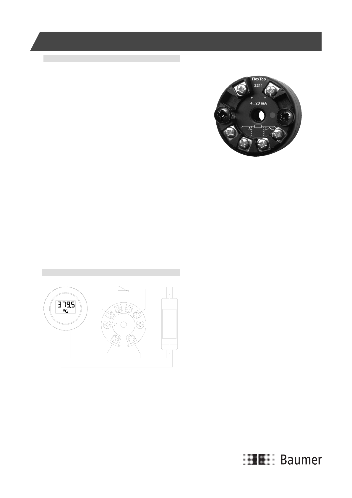
Non-Ex Application
24 V
230 V
3 4
1 2
+ -
dc
RTD
45
3
- +
6
2 1
- +
4...20 mA
FlexView FlexTop 2211 Power supply
This Ex-approved product is manufactured by:
Baumer A/S
Jacob Knudsens Vej 14
DK-8230 Aabyhoej
Denmark
ac
Installation Manual 5850-032www.baumer.com
Page 1 Design and specifi cations subject to change without notice
Page 2
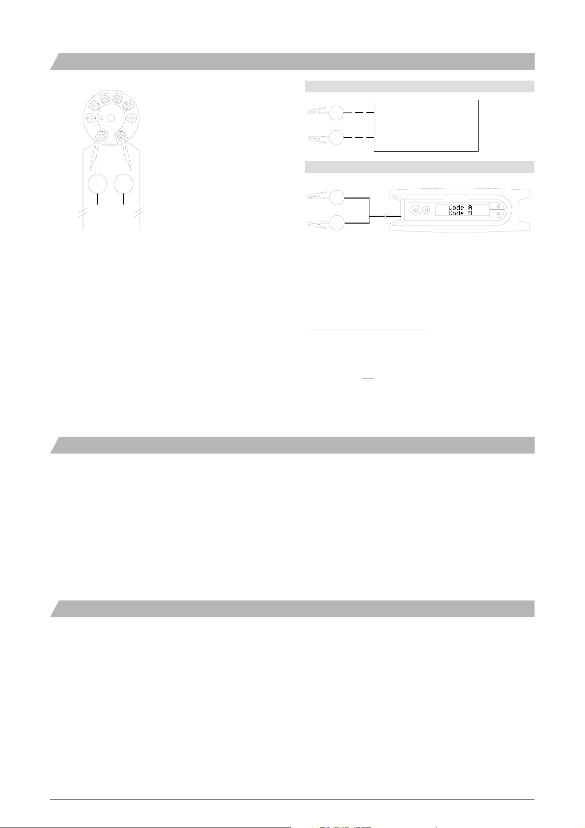
Confi guring with FlexProgrammer
Note:
Disconnect loop supply before
connecting the FlexProgrammer
2 1
2 1
to FlexTop 2211.
FlexProgrammer
1
FlexProgrammer
2
FlexProgrammer 9701
Red clip
1
2
Black clip
Note: Ambient temperature range 0...50°C
The FlexTop 2211 can be confi gured, us ing the 4...20 mA cable.
The max i mum dis tance de pends on the cable type, re sist ance and
ca pac i ty. We rec om mend to use screened cables.
To be able to confi gure the FlexTop 2211 with the FlexProgrammer the
dedicated software, Flex-program, must be loaded on the PC.
The Flex-program has help menus for all func tions.
During the confi guration the new data are, by means of the FlexPro-
grammer, trans ferred from the PC to the FlexTop 2211, where they are
stored in the in ter nal mem o ry.
Ex-Confi guring
None of the two types of FlexProgrammer confi guring unit must be
connected to the FlexView within the hazardous area.
Confi guring procedure:
a) Disconnect mains from the 4...20 mA loop circuit.
b) Disconnect the FlexTop 2211 from the circuitry within
the hazardous area.
c) Bring the FlexTop 2211 to the safe area.
d) Connect the FlexProgrammer and perform the
confi guring session.
e) Re-install the FlexTop 2211 in the hazardous area.
f) Connect the power supply to the circuit.
The indication for a correct con fi g u ra tion se quence is:
1) The LED on the FlexTop 2211 lights up constantly.
Error indications during confi guration:
1) The LED on the FlexTop 2211 is not lighting.
3) An error message comes up on the PC.
Note: During the fi rst power-up after a confi guration the power-on time
increases to approx. 10 sec.
LED Function
The LED of the FlexTop indicate the actual status of the measured
value. The LED will be turned on continually as long as the measured
value result in an output current between 4 and 20mA. If the output
current is higher than 20mA or lower than 4mA the LED will twinkle
with 1Hz. The same twinkling behavior will occur if a sensor break
error is detected.
Installation Manual 5850-032www.baumer.com
Page 2 Design and specifi cations subject to change without notice
Page 3

Ex-Application
A FlexTop 2211 with type number 2221 0002 is approved for Ex ia IIC
T5/T6 and ATEX II 1G.
The installation of FlexTop 2211 must be done in accordance with
prevailing guidelines for zones 0 or 1.
An Ex ia certifi ed zener or isolation barrier with the entity parameters
V
< 30 VDC; I
max
The FlexTop 2211 entity parameters (terminals + to -) are:
Li < 15 µH; Ci < 5 nF.
< 0.1 A; P
max
< 0.75 W must be used.
max
Sensor circuit parameters (terminals 3 to 6):
V
< 6.6 V; IDC < 17 mA; P
DC
The FlexTop 2211 must be connected in the 4...20 mA loop circuit only.
FlexTop 2211 must be mounted in a housing, e.g. ø80mm stainless
steel housing (type number 81 43-110), DIN-B housing (type number
81 43-120) or the like.
Refer to page 3 for futher technical data.
WAR NIN G
This product contains no replaceable parts.
In case of malfunction the product must be shipped to Baumer for
repair.
< 30m W; La < 99 mH; Ca < 3µF.
out
Ex-Connection Diagram/Control Drawing
RTD Zone 0/1 Safe area 230 V
3 4
5
6
4
3
ac
21
- +
- +
1 2
+ -
4...20 mA 24 V
FlexTop 2211 Barrier FlexView Power Supply
Ex nA II T5, ATEX II 3G - Installation
A FlexTop 2211-0003 is Ex nA II T5, ATEX II 3G approved for application in hasardous areas in accordance with the current EU-directives. The product must be mounted in a suitable enclosures fulfi lling
relevant requirement in EN 60 079-0 among these minimum IP54
ingress protection.
Ex-data
Supply range 12...30 VDC, Max. 0,1A
Temperature class T1...T5.
dc
Installation Manual 5850-032www.baumer.com
Page 3 Design and specifi cations subject to change without notice
Page 4

Electrical Installation
RTD T/C Potentiometer Resistance
+
T/C
R
No cable Internal CJC- No compensation {3}
compensation {3}
compensation
No compensation {3}
R
RTD T/C Potentiometer Resistance
+
R
RTD T/C
3-wire cable External CJC-compensation 3-wire compensation for
compensation
No cable compensation {3} transfer resistance {4} compensation
R
3-wire cable
RTD T/C Potentiometer Resistance
+
RTD T/C
4-wire cable External CJC-compensation 4-wire compensation for
compensation
3-wire cable compensation transfer resistance {4} compensation
R
Current measurement Voltage measurement Notes
{3} Confi gurable compensation for cable resistance
{4} Transfer resistance between element and wiper
Accessories
R
I
Dimensional drawing
ø44 26.3
+
The FlexProgrammer 9701 is a dedicated tool to confi gure all
Baumer confi gurable products.
Type No. 9701-0001 complies:
FlexProgrammer
ø6
33
ø4 mounting hole.
Spring loaded
mounting screws.
Cable with 2 aligator clips
Cable from FlexProgrammer to M12 plug for TE2
Cable from FlexProgrammer to M12 Plug for LFFS, LBFS and CPX
USB cable
CD with the FlexProgram software
R
4-wire cable
5850-032/ B1 This data sheet may only be reproduced in full.
Installation Manual 5850-032www.baumer.com
Page 4 Design and specifi cations subject to change without notice
 Loading...