

Page 1
FlexBar 3431 Pressure Transmitter
Safety instructions
This instrument is built and tested ac cord ing to the current EU-directives and packed in technically safe con di tion. In order to main tain this
condition and to ensure safe op er a tion, the user must follow the hints
and warnings given in this instruction.
During the installation the valid national rules have to be observed.
Ignoring the warnings may lead to severe per son al injury or substantial
damage to property.
The product must be op er at ed by trained staff. Correct and safe
operation of this equipment is de pend ent on proper transport, storage,
installation and op er a tion.
All electrical wiring must conform to local stand ards. In order to prevent
stray elec tri cal radiation, we rec om mend twisted and shielded input
cables, as also to keep power sup ply cables separated from the input
cables. The con nec tion must be made ac cord ing to the connecting
di a grams.
Before switching on the power supply take care that other equip ment
is not af fect ed. Ensure that the supply voltage and the conditions in the
environment comply with the spec i fi ca tion of the de vice.
Before switching off the supply voltage check the possible effects on
other equipment and the processing system.
WARNING
For electrical installation and com mis sion ing of explosion protected
devices, the data given in the con form i ty cer tifi cate as also the local
reg u la tions for installation of elec tri cal apparatus within explosion pro tect ed areas must be considered. The intrinsically safe versions can be
mounted in the explosion hazarded area according to its spec i fi ca tion
only con nect ed to a certifi ed intrinsically safe supply loop with the cor re spond ing electrical values.
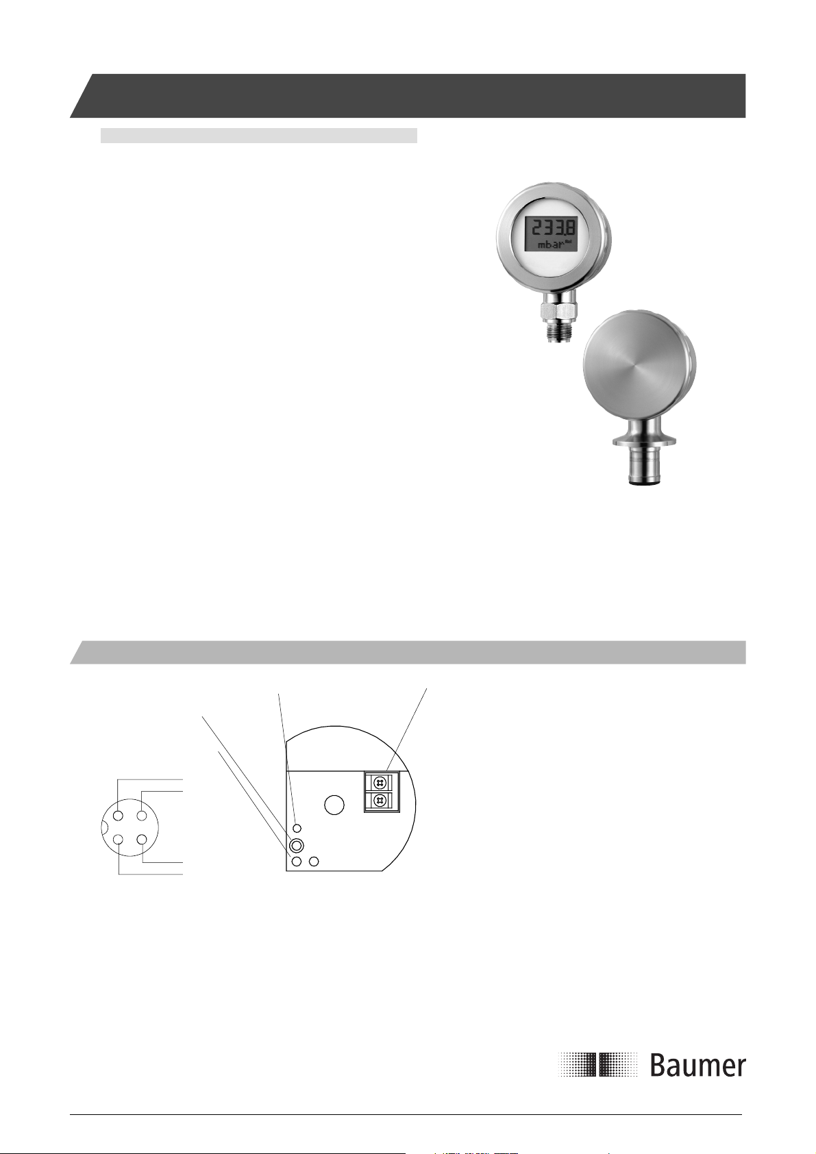
Electrical Installation
LED, lights during auto zero adjustment
Auto Zero push button
1 & 2: Pins for connection
of FlexProgrammer
1 (+)
4 N. c.
3 (-)
2 N. c.
Plug M12, male
This Ex-approved product is manufactured by:
Baumer A/S
Jacob Knudsens Vej 14
DK-8230 Aabyhoej
Denmark
FlexBar
Zero
1 2
+1
-2
®
Profi bus
2-wire twisted pair with shield
WARNING: According to the Profi bus PA standard the cable shield
®
must be terminated in the cable gland connected to the instrument
housing.
To secure maximum tightness in the gland the correct cable diameter
should be used.
WARNING: The pins 1 & 2 must not be connected to other equipment
than the dedicated FlexProgrammer.
(Max. 15V/50mA on the pins)
PA cable
Installation Manual 5850-016www.baumerprocess.com
Page 1 Design and specifi cations subject to change without notice
Page 2
Installation
1)
Factory guarantee is void on mechanical damages on the diaphragm.
Die Werksgarantie erstreckt sich nicht auf mechanische Schäden der Membran.
Les détériorations mécaniques de la membrane ne sont pas couvertes par la garantie .
Mekanisk skade på membranen er ikke omfattet af fabriksgarantien.
Mekaniska skador på trycktransmitterns membran omfattas inte av garantin.
Takuu ei koske käytön aikana tullutta mekaanista vauriota kalvossa.
2)
>22 mm
Unpacking the transmitter
If the transmitter is visibly damaged, it should not be put into operation.
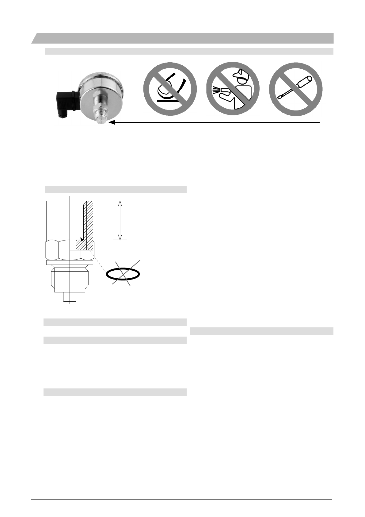
Installation procedure
a) Remove protection-cap.
b) Install FlexBar 3431.
If a G1/2A version: Tighten up at 20 Nm.
c) Confi gure the display with a FlexProgrammer.
d) Establish a zero pressure condition (e.g. empty the tank)
d) Press and hold the Auto Zero button to reset the FlexBar.
Mechanical installation and cleaning
The pressure diaphragm must not be touched during installation.
Cleaning with pressurised cleaners and tools may damage the
diaphragm.
Refer to drawing no. 2:
If the transmitter has a 1/2” threaded neck, check before mounting
in a blind hole that the thread length is at least 22 mm. Use a gasket
ø28.6 x ø21.5 mm, made from a material proof against the measuring
medium, and do the clamping with an NV27 mm engineer’s wrench.
FlexBar 3431 can be mounted on a Baumer pressure gauge connection type no. 81 26-92X.
For a FlexBar 3431 with a 3A/DN38 connection an O-ring with the
dimensions ø3.0 x ø19.0 mm must be used.
Mounting the pressure transmitter in closed systems (e.g. a stop cock)
can create overpressure in excess of that permit ted (400%), which
could deform the diaphragm and damage the pressure sensor.
The transmitter must not be exposed to pressure or surge exceeding 4
x span, max. 600 bar though.
The freezing point of process media and condensates must be
checked to prevent unintentional pressure rise when it is freezing.
Radiated heat may create excessively higher opera ting tempera tures
than the allowed -40...85°C (without display).
Adjusting the zero point
With FlexBar 3431 the electronic zero point can be adjusted from
-10...10% of the total measuring range.
The correct zero point pressure must be established prior to adjusting the zero point. Tank and pressure transmitter must have the same
temperature. If the pressure transmitter has a relative measuring cell
from 0 bar, the zero point pressure is the same as the atmospheric
pressure or the level in a tank selected as zero point level. A pressure
transmitter measuring absolute pressure has a zero point lower than 1
mbar abs.
When the required zero point pressure has been established, the Zero
push button inside FlexBar must be pressed and held. The LED will
respond with one blink per second. When the actual zero pressure
level has been stored in the memory of the FlexBar the LED will blink
twice a second.
You can revert to the factory setting by reconfi guring the FlexBar 3431
in the PDM setup. The pressure transmitter can change its zero point
slightly, due to mechanical tension and the mounting direction selected
for the pressure diaphragm. Optimal results are therefore achieved
if the zero point is adjusted after the pressure transmitter has been
mounted in place.
Installation Manual 5850-016www.baumerprocess.com
Page 2 Design and specifi cations subject to change without notice
Page 3

Confi guration - Overview
Confi guration of FlexBar 3431 FlexBar 3431 Profi bus PA FlexProgrammer
Engineering units for the display (optional) x
Enable/disable the address button at the display x
Enable/disable the display function x
Device address setting (if display mounted/enabled) x x x
Engineering units for Profi bus PA output x
TA G x x
Zero point calibration x
2-point calibration x
Factory settings x
Measuring limits and ranges x
Scaling x
Warning and Alarm limits x
Damping x
Output limits and engineering unit x
Linearisation table x
Confi guration Setting the device address
Unless specifi ed the FlexBar 3431 will be confi gured with device
address 126.
®
FlexBar 3431 can be confi gured either online via the Profi bus
network or offl ine with the dedicated Baumer FlexProgrammer unit
connected to a standard PC.
The following parameters can be confi gured using the FlexProgrammer:
Proces Value Scale corresponding to 0...100% output at the display.
Enable/Disable the push button at the display.
Set the transmitter device address.
Set/change the display engineering unit.
In a Profi bus
device, such as measuring limits, linearisation, damping, one- or two
points calibration, alarm limits, etc. can be confi gured.
®
PA network all standard parameters for a PA pressure
PA
Confi guring with FlexProgrammer
WARNING:
Disconnect the Profi bus PA wires before connecting
the FlexProgrammer to FlexBar 3431.
The push button at rear of the display is for control and setting of the
transmitter device address.
Monitor the address: Push the button once.
Change the address: Push the button in 5 secs., the display fl ashes.
Increase address by 1: Push the button again.
Increase address by >1: Push and hold the button.
No activity for 5 secs.: The display shows the process value and the
new address has been activated.
The push button can be enabled/disabled using the FlexProgrammer
FlexProgrammer
1
FlexProgrammer
2
FlexProgrammer 9701
Red clip
1
2
Black clip
Note: Ambient temperature range 0...50°C
Installation Manual 5850-016www.baumerprocess.com
Page 3 Design and specifi cations subject to change without notice
Page 4

Ex-application
Zone 0/1 Safe area
FlexBar 3431 Zener barrier/coupler/link
Approval Ex ia IIC T4/T5, ATEX II 1G
Internal inductivity L
Internal capacity C
Coupler/link FISCO Standard;
Zener barrier U < 20 V
Temperature class T1...T4: -30 < T
Note: With a readable display the lowest temperature is -10°C
< 10 µH
i
< 5 nF
i
U: 17.5 V
; I: All ; P: All
dc
; I < 0.1 A ; P < 0.75 W
dc
T5: -30 < T
< 85°C
amb
< 60°C
amb
FlexBar 3431 is approved for Ex ia IIC T4/T5 and ATEX II 1G according to the current EU-directives.
FlexBar 3431 must be installed in accordance with prevailing
guidelines for zone 0 or 1, and a certifi ed, intrinsically safe zener
barrier
with the maximum values U
= 20 Vdc; I
max
= 0.1 A ; P
max
= 0.75 W
max
must be used.
Alternatively FlexBar 3431 can be connected to a Profi bus DP/PA
converter, such as coupler or link. The maximum specifi cations must
follow FISCO standards and not exceed:
U
= 17.5 Vdc; I: All ; P: All
max
Ex-confi guring
None of the two types of FlexProgrammer confi guring unit must be
connected to the FlexView within the hazardous area.
Confi guring procedure:
a) Disconnect the FlexBar 3431 from the circuitry within the
hazardous area.
b) Bring the FlexBar to the safe area.
c) Connect the FlexProgrammer and confi gure the FlexBar.
d) Re-install the FlexBar in the hazardous area.
e) Re-connect the signal cable.
WARNING
This product contains no replaceable parts.
In case of malfunction the product must be shipped to Baumer for
repair.
WARNING
Products with painted and/or plastic surfaces (e.g. display) imply a risk
of electrostatic charging.
To prevent electrostatic hazard - do only clean with a moist cloth.
After mounting the device - do check that the housing has a ground
potential.
5850-016/2008-06-12/Rev. A1 This data sheet may only be reproduced in full.
Installation Manual 5850-016www.baumerprocess.com
Page 4 Design and specifi cations subject to change without notice
 Loading...