

Page 1

Operating Instructions
Smart Reflect
FNDH 14G6901/IO
FNDH 14G6901/KS34A/IO
FNDR 14G6901/S14/IO
FNDK 14G6904/IO
FNDK 14G6904/S35A/IO
FNDK 14G6904/S14/IO
Background suppression
FHDH 14G6901/IO
FHDH 14G6901/KS34A/IO
FHDR 14G6901/S14/IO
Page 2

Operating Instructions for Series 14 Hygienic and Washdown
Design with IO-Link
Contents
1
1.1
1.2
2
2.1
2.2
2.3
3
4
4.1
4.1.1
4.2
4.2.1
4.2.2
4.2.3
4.2.4
General information ..................................................................................................................... 3
Concerning the contents of this document ..................................................................................... 3
General information ........................................................................................................................ 3
IO-Link introduction ..................................................................................................................... 4
SIO mode ........................................................................................................................................ 4
IO-Link communication mode ......................................................................................................... 4
IODD (IO-Link device description) .................................................................................................. 5
Sensor in SIO mode ..................................................................................................................... 5
Sensor in IO-Link communication mode ................................................................................... 5
Process data ................................................................................................................................... 5
Process data structure .................................................................................................................... 5
Parameters and commands ........................................................................................................... 6
Product data ................................................................................................................................... 6
Parameters ..................................................................................................................................... 6
Commands ..................................................................................................................................... 6
Saving changes .............................................................................................................................. 6
5
5.1
5.1.1
5.1.2
5.1.3
5.1.4
5.1.5
5.2
5.2.1
5.2.2
6
6.1
6.2
6.3
6.4
6.5
Explanation of sensor configuration .......................................................................................... 7
Teach-in of a user-specific switching point ..................................................................................... 7
Parameters ..................................................................................................................................... 7
Commands ..................................................................................................................................... 7
Description ...................................................................................................................................... 7
Hysteresis ..................................................................................................................................... 10
Error correction ............................................................................................................................. 10
Dirt indicator .................................................................................................................................. 10
Parameters ................................................................................................................................... 10
Description .................................................................................................................................... 10
Configuration .............................................................................................................................. 12
Table of general parameters ......................................................................................................... 12
Table of work parameters ............................................................................................................. 12
Table of system commands .......................................................................................................... 13
Table of error codes ...................................................................................................................... 13
Table of factory settings ................................................................................................................ 13
en_BA_FNDx14_FHDx14_IO.doc 2/14 Baumer Electric AG
12.04.2013/hem Frauenfeld, Switzerland
Page 3

1 General information
1.1 Concerning the contents of this document
This manual contains information regarding the commissioning and communication of Baumer series 14
photoelectric diffuse sensors with SmartReflect and background suppression with the IO-Link interface. It is a
supplement to the mounting instructions supplied with each sensor.
This manual applies to the following sensor types:
Diffuse sensors with SmartReflect technology
FNDH 14G6901/IO
FNDH 14G6901/KS34A/IO
FNDR 14G6901/S14/IO
FNDK 14G6904/IO
FNDK 14G6904/S35A/IO
FNDK 14G6904/S14/IO
Diffuse sensors with background suppression
FHDH 14G6901/IO
FHDH 14G6901/KS34A/IO
FHDR 14G6901/S14/IO
1.2 General information
Intended
use
Commissioning Installation, mounting and adjustment of this product may be performed only by a
Mounting For mounting, use only the mechanical mountings and mechanical mounting
en_BA_FNDx14_FHDx14_IO.doc 3/14 Baumer Electric AG
12.04.2013/hem Frauenfeld, Switzerland
This product is a precision device and is used for object detection and the
preparation and/or provision of values as electrical quantities for a subsequent
system.
Unless this product is specially labeled, it may not be used for operation in
potentially explosive environments.
qualified person.
accessories intended for this product.
Unused outputs must not be wired. In cable versions with unused cores, these cores
must be insulated. Do not exceed admissible cable bending radii. Prior to electrical
connection of the product, the system must be disconnected from the power supply.
In areas where screened cables are mandatory, they must be used as protection
against electromagnetic disturbances. If plug connections to screened cables are
made by the customer, an EMC version of the connectors should be used, and the
screen must be connected to the connector housing across a large area.
Page 4

2 IO-Link introduction
These operating instructions contain a description of the most important aspects of the IO-Link interface
which are required for understanding the configuration options. For detailed information about IO-Link and all
specifications, go to www.io-link.com .
IO-Link is a standard interface for sensors and actuators. The device (sensor, actuator) and IO-Link master
are interconnected as a point-to-point connection. Communication between master and device takes place
bi-directionally via the device connecting line. Via this interface values can be read out and it is possible to
configure the sensor via IO-Link. The sensor can be operated in two modes: standard input/output mode
(SIO mode) and IO-Link communication mode.
The master switches the sensor to IO-Link communication mode. In this mode, process data are
continuously sent from the sensor to the master and demand data (parameters, commands) are written to
the device or read off it.
2.1 SIO mode
After start-up the sensor is in SIO mode. In this mode the sensor functions as a normally switching sensor.
On the master side the IO-Link port is switched as a normal digital input. The sensor can be used like a
standard sensor without IO-Link. Diverse functions can, however, only be controlled via IO-Link.
2.2 IO-Link communication mode
With a so-called "wake-up" the sensor is switched by the master into "communication mode". In the process
the master attempts to find a connected device through a defined signal on the switching line. If the sensor
responds, communication parameters are exchanged and afterwards cyclical transmission of process data is
initiated.
In IO-Link communication mode:
• Process data can be read.
• Parameters can be read off the sensor.
• Parameters can be written to the sensor.
• Commands can be sent to the sensor (e.g. teaching the switching point, restoring to factory setting,
etc.).
In the process data cyclical data such as outputs or quality data are transmitted to the superordinate control.
The master can leave the IO-Link communication mode again with a "fall back", and the sensor continues to
operate in SIO mode until a new "wake up".
In IO-Link communication mode, sensor behavior can be adjusted in SIO mode so that the sensor can easily
be parameterized according to requirements and then operate as a "normal" sensor without the IO-Link
master. Alternatively, the sensor can also be operated in IO-Link communication mode, enabling use of the
full range of functions via process data.
en_BA_FNDx14_FHDx14_IO.doc 4/14 Baumer Electric AG
12.04.2013/hem Frauenfeld, Switzerland
Page 5

2.3 IODD (IO-Link device description)
The IODD describes the IO-Link device and can be downloaded at www.baumer.com. It consists of a set of
XML and PNG files. An engineering tool or diagnosis tool reads the IODD of a sensor and therefore knows
its:
• Identification (manufacturer, designation, article number, etc.)
• Communication characteristics (communication speed, frame type, etc.)
• Parameters and commands
• Process data
• Diagnosis data (events)
Sensor data that can be viewed and changed is defined by the IODD. The manner of data representation
and manipulation is defined by the control manufacturer and is therefore sensor-independent.
3 Sensor in SIO mode
In SIO mode the sensor operates according to the factory settings or the settings adjusted by the user via
IO-Link. The range of functions in SIO mode is sensor-specific.
4 Sensor in IO-Link communication mode
4.1 Process data
If the sensor is in IO-Link communication mode, data are periodically exchanged between the IO-Link master
and the device. These data consist of process data and possible commands and parameters to the sensor.
In the process data the current measuring value and status bits like output, quality data, etc. are transmitted
to the master. The process data do not have to be explicitly queried by the master.
4.1.1 Process data structure
Figure 1 shows the process data structure. A brief description of the individual data is provided in the
following.
4.1.1.1 Back-up
Bit4…Bit15 serve solely as a back-up and are reserved with the value 0.
4.1.1.2 Meaning of status information
Bit 0: Alarm
The alarm bit indicates whether an object is in the defined scanning range (e.g. 50 to 400 mm)
Bit0 = 0 → There is an object is in the scanning range
Bit0 = 1
→ There is no object in the scanning range
Bit4…Bit15
Figure 1: Process data
Bit3
Bit2
Bit1 Bit0
en_BA_FNDx14_FHDx14_IO.doc 5/14 Baumer Electric AG
12.04.2013/hem Frauenfeld, Switzerland
Page 6

Bit 1: Switching bit
The switching bit assumes the function of the switching output in IO-Link communication mode
Bit1 = 0
Bit0 = 1
→ There is no object in th
e switching range
→ There is an object in the switching range
Bit 2: Quality
This bit provides information about the quantity of light reflected by the object (dust indicator).
Bit2 = 0
→ reflected light above the threshold (sufficient signal)
Bit2 = 1 → reflected light below the threshold (weak signal)
Bit3: Not used
4.2 Parameters and commands
Parameters and commands are written to the device or read off the device via indices. The read and write
function of indices is provided by the IO-Link master. The user can write a value into an index or read a value
off an index.
4.2.1 Product data
Some parameters contain product information like manufacturer's name, product name, and number, plus
room for a user-specific designation of the sensor (see: 6.1 Table of general parameters).
4.2.2 Parameters
For a description of the parameters, see 6.2 Table of work parameters.
The following settings are possible via parameters:
• Setting the switching point (numerical or manual teach-in)
• Defining the output state (light or dark switching)
• Selecting a teach-in function
• Setting a delay function at the switching output. Value range from 1 to 1000 ms
• Defining the threshold for the dust indicator
4.2.3 Commands
Commands are written to index 0x02 (system command). For a description of the commands, see 6.3 Table
of system commands.
The following settings can be made via commands:
• Teach-in and application of the switching point
• Save changed parameters
• Restore to factory settings
4.2.4 Saving changes
If parameter changes are made by directly writing parameters or by a command (also restoring to factory
settings), the settings must be permanently saved by the command Save parameters. Otherwise the
changes are lost after the sensor is restarted, and the last saved entries are reactivated.
en_BA_FNDx14_FHDx14_IO.doc 6/14 Baumer Electric AG
12.04.2013/hem Frauenfeld, Switzerland
Page 7

5 Explanation of sensor configuration
The functionality of the sensor can be configured with the parameters and the commands. In the following
sections, the individual configuration options are explained in detail.
5.1
5.1.1 Parameters
Switching points work: This parameter contains the currently used switching point and can be
Teach-in positions interim: This parameter serves as an interim register for teaching-in the switching
5.1.2 Commands
Teach-in position A: Command for teaching-in position A. The taught-in value is transferred to
Teach-in position B: Command for teaching-in position B. The taught-in value is transferred to
Transfer switching points: The positions A and B taught into the interim register Teach-in position
Teach-in of a user-specific switching point
written directly (numerical teach-in) or set automatically to an object via the
interim register during teach-in. The parameter consists of two 16-bit
parameters Switching point A and Switching point B, whereby one
switching point respectively must have the value 65535 (corresponds to
"not valid").
- Unit: 1 mm
- Factory setting: Switching point A = 50mm, Switching point B =
65535 "not valid"
point to an object (1-point teach-in) or to a reference position and an object
(2-point teach-in). The parameter consists of two 16-bit parameters Teach-
in position A interim and Teach-in position B interim.
- Unit: 1 mm
the interim register Teach-in position A interim.
the interim register Teach-in position B interim.
interim are offset against one another, transferred to the working register
Switching points work and activated.
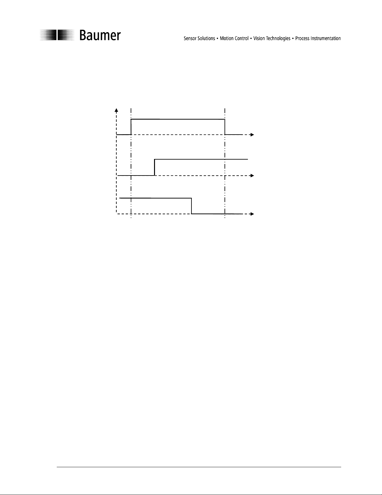
5.1.3 Description
The switching point of the sensors described here can be adjusted by the user in two ways:
• Numerical teach-in: The switching point can be written directly into the parameter Switching points
work. The two parameters selected for the switching point must not be smaller than 50 mm and not
larger than 400 mm for sensors with background suppression (or 800 mm for SmartReflect). One
parameter respectively must be 65535 (not valid). The switching function (light/dark switching) is
defined by the selection of the switching point parameter (A/B).
• Teach into object (1-point teach-in): The switching point is taught into an object for measurement
with the command Teach-in position. The switching function (light/dark switching) is defined by the
selection of the teach-in parameter (A/B). If the object is outside of the adjustable sensing distance,
the minimum or maximum sensing range is taught in.
• Teach into reference position and object (2-point teach-in): To teach in the switching point with 2-
point teach-in, the command Teach-in position must be executed at two positions: once to a solid
reference position (background of the object or a reflecting machine part) and once to the object
en_BA_FNDx14_FHDx14_IO.doc 7/14 Baumer Electric AG
12.04.2013/hem Frauenfeld, Switzerland
Page 8
0
0
0
1
1
1
Switching bit/Switching output
A
B
A
B
50mm 400mm
itself. Both teach-in parameters must be within the adjustable sensing distance and be more than 4%
of the sensing distance apart. The switching function (light/dark switching) is defined by the order of
the teach-in parameters (A/B).
Adjustable sensing
distance
(Calibration curve 1)
Taught-in sensing range
(Calibration curve 2)
Inverted sensing range
(Calibration curve 3)
Figure 2: Possible switching curves
5.1.3.1 Sample numerical teach-in:
1) A switching point is set at 150 mm (A) (Calibration curve 2).
Point A absolute in mm: 150 mm → 0096 hex (= Switching point A)
Point B absolute in mm: not valid → FFFF hex (= Switching point B)
Parameter to be written:
Switching points work: 0096FFFF hex
Save parameters to save the values permanently!
2) The sensing range is set inversely at 200 mm (B) (Calibration curve 3).
Point A absolute in mm: not valid → FFFF hex (= Switching point A)
Point B absolute in mm: 200 → 00C8 hex (= Switching point B)
Parameter to be written:
Switching points work: FFFF00C8 hex
Save parameters to save the values permanently!
en_BA_FNDx14_FHDx14_IO.doc 8/14 Baumer Electric AG
12.04.2013/hem Frauenfeld, Switzerland
Page 9
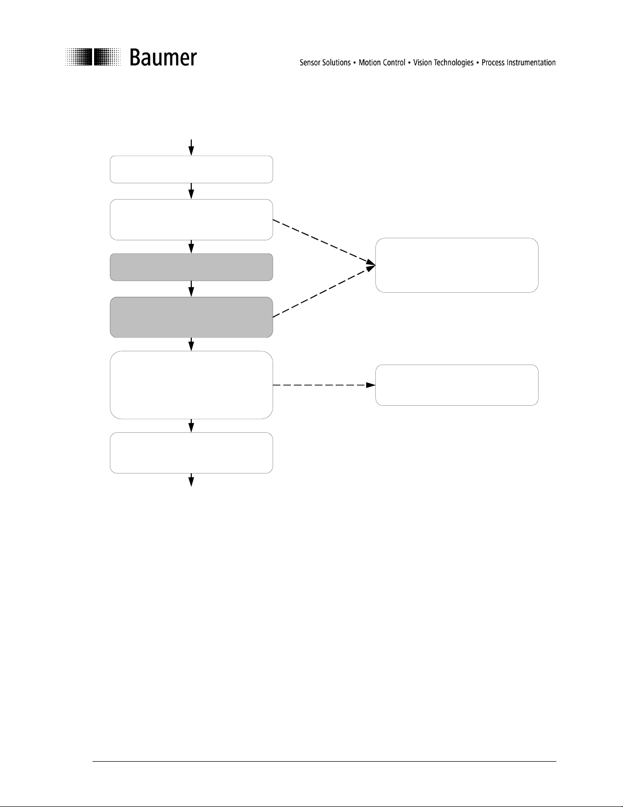
5.1.3.2 Sample teach-in to object
Teach
-
in
The sensing range is taught into an object (Calibration curve 2).
Place object at the desired
switching point
Read taught-in position into the
interim register with the command
Teach-in Position A
Align sensor to reference object
(reflector or background)
Read taught-in position into the
interim register with command
Teach-in Position B
The interim registers
positions interim can be read
out at any time, and the read-in
values can be checked
Transfer switching points from
the interim register to the working
register and activate them with
the command Transfer
After transfer into the working
register, the interim register is
reset to FFFF FFFF hex
switching points
Save the changes permanently
with the command Save
parameters
Figure 3: Teach-in switching range
Fields highlighted in gray are required only for teach-in with 2-point teach-in.
For an inverted switching range (Calibration curve 3):
• The command Teach-in Position B must be used instead of Teach-in Position A for 1-point teach-
in.
• For 2-point teach-in the distance from the sensor to Teach-in Position A must be greater than the
distance to Teach-in Position B.
en_BA_FNDx14_FHDx14_IO.doc 9/14 Baumer Electric AG
12.04.2013/hem Frauenfeld, Switzerland
Page 10
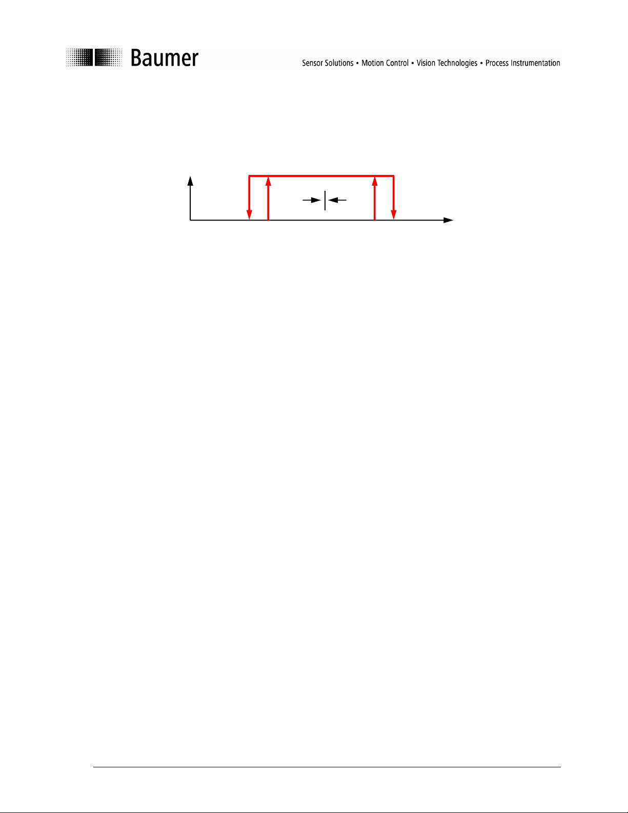
5.1.4 Hysteresis
In the direction of approach to the sensing range, the sensor actuates exactly at the taught-in switching
points. When the sensing range is re-exited, a hysteresis is added (see: Figure 4).
Switching bit/Output
1
0
Distance
A B
Figure 4: Hysteresis switching range
5.1.5 Error correction
The difference of the learning positions (distance between object and background/reflector) is too small; that
is they are closer together than 4% of the sensing range.
• Error message Interfering parameter (see: 6.4 Table of error codes)
• Interim is set to FFFF FFFF hex
• Last valid values remain activated
The taught-in switching points are outside of the scanning range (see data sheet):
• Numerical teach-in: Writing Switching points work is not possible, error message Parameter value
out of range, last valid values remain activated.
• 1-point teach-in: Error message Parameter value out of range, the sensor is adjusted to maximum
or minimum sensing distance.
• 2-point teach-in: Teach-in positions interim are not transferred, error message Parameter value
out of range, last valid values remain activated.
5.2 Dirt indicator
5.2.1 Parameters
Nominal value quality parameter: Threshold for quality evaluation of the received signal. If the received
light quantity drops below this threshold, the quality bit is set in the
process data.
- Value range: 1-8
- Factory setting: 7
Quality parameter: Actual value of reception quality.
5.2.2 Description
Via the sensor exposure control it is possible to determine whether sufficient excess gain is still available for
reliable measurement. This excess gain is represented quantitatively by the Quality parameter. If the
Quality parameter drops below the threshold specified in the Nominal value quality parameter, this is
indicated with the quality bit of the process data.
en_BA_FNDx14_FHDx14_IO.doc 10/14 Baumer Electric AG
12.04.2013/hem Frauenfeld, Switzerland
Page 11

Application example:
During application setup it is possible to take account of this by reading out the Quality parameter regularly
to determine its lowest value. Then the threshold Nominal value quality parameter can be set 1-2 levels
lower. If the Quality parameter drops below this threshold for any reason during operation, this is indicated.
At that moment the application still works properly, however the sensor should be checked some time.
Possible reasons for activation of the Quality parameter may be:
Sensor is soiled → Sensor must be cleaned
Sensor has been moved → Readjust sensor
Something in the application has changed, e.g. varying object surface finishes → Readjust
sensor (Nominal value quality parameter) if necessary.
With the aid of this function, it is possible to detect sensor failure at an early stage and take appropriate
action.
Important: The sensor still functions properly even with a Quality parameter of 1. It is not absolutely
necessary to achieve the highest possible value!
en_BA_FNDx14_FHDx14_IO.doc 11/14 Baumer Electric AG
12.04.2013/hem Frauenfeld, Switzerland
Page 12
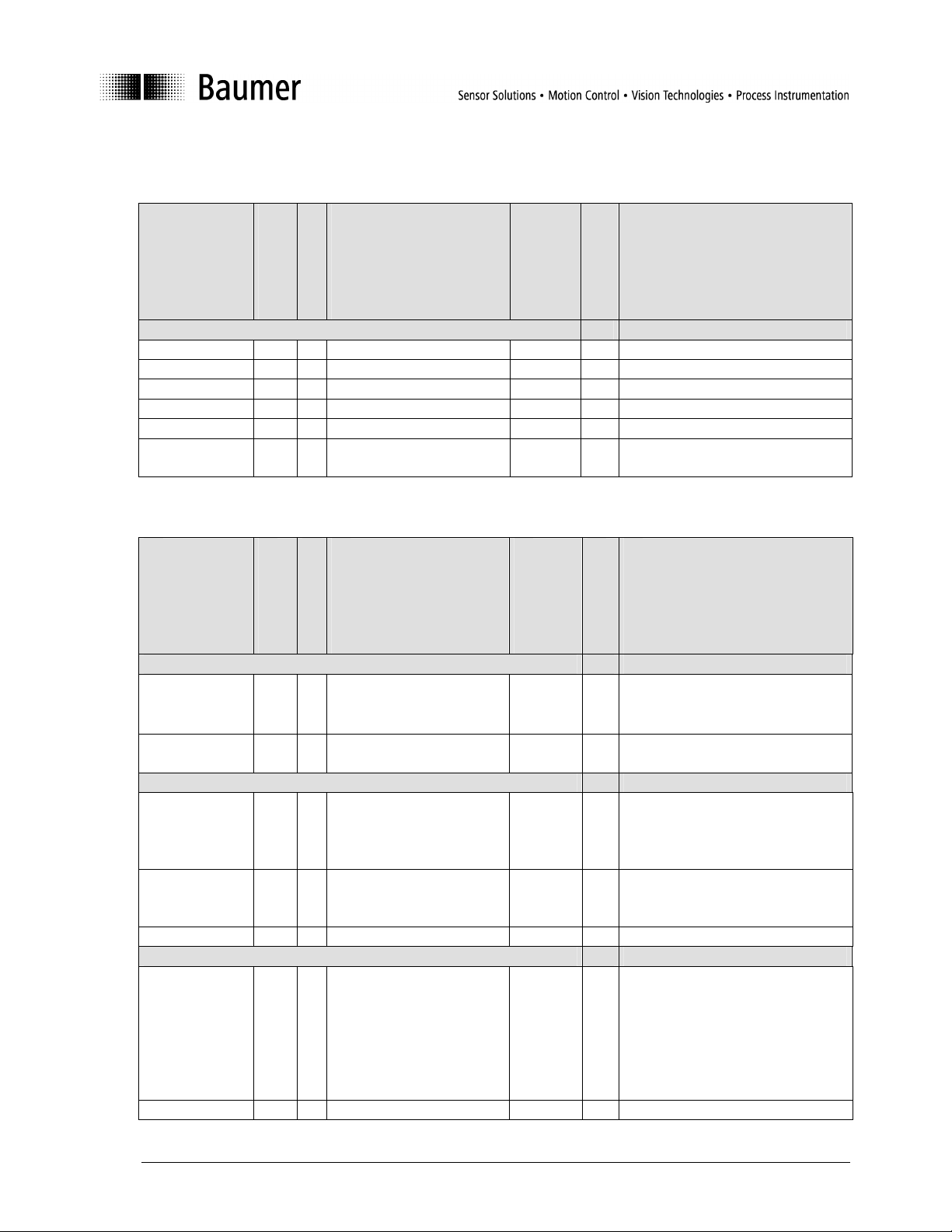
6 Configuration
6.1
General information on sensors
Vendor Name 0X10 18 String ASCII R “Baumer Electric AG“ for all sensors
Product Name 0X12 22 String ASCII R Corresponds to Baumer article description
Product ID 0X13 8 String ASCII R Corresponds to Baumer article number
Serial Number 0X15 4 String ASCII R Baumer P-Code
Firmware Revision 0X17 8 String ASCII R Baumer Firmware Revision
Application Specific
Name
Table of general parameters
SPDU name
SPDU index
Number of Bytes
0X18 8 - - R/W 8 Byte at customer disposal
Format
Range of values
R/W
Comments
6.2 Table of work parameters
SPDU name
Teach-in and switching points
Switching points
work
Teach-in positions
interim
Sensor functions
Teach function 0X60 1 0 = One point Teach-in
Nominal value
quality parameter
Quality parameter 0X66 1 1..8 or 255 R
Output functions
Output delay
function
Output delay time 0x72 2 Byte 1…2, time in 1ms 0…1000 R/W Delay time
SPDU index
Number of Bytes
Format
0X40 4 Switching point A (HB, LB)
Switching point B (HB, LB)
0X41 4 Teach-in Position A (HB, LB)
Teach-in Position B (HB, LB)
(Reference position)
2 = Two point Teach-in
(ON/OFF-position)
0X65 1 1..8 R/W Provided the internal quality parameter
0x71 1 Byte 0 (Subindex 1)
0 = no delay
1 = on delay
2 = off delay
3 = minimum pulse
4 = single shot positive edge
5 = single shot negative edge
Range of values
50…400 R/W Distance information on switching points,
50…400,
65535
0.2 R/W Selection of Teach mode
0…5 R/W Choose delay funciton
R/W
Comments
calculated from the information on Teachin position interim
R Distance information on Teach-in position
drops below this threshold the switching
output is set.
en_BA_FNDx14_FHDx14_IO.doc 12/14 Baumer Electric AG
12.04.2013/hem Frauenfeld, Switzerland
Page 13

6.3 Table of system commands
Name of
Command
Restore factory setting 0X02 0X82 Restores all original factory settings of the sensor
Teach-in position A 0X02 0XA0 Teach-in of switching point A. The measured distance is written into the interim Teach in
Teach-in position B 0X02 0XA1 Teach-in of switching point A. The measured distance is written into the interim Teach in
Transfer switching
positions
Save parameters 0X02 0XE0 Save all parameters in Flash memory
SPDU Index
CMD Value
Comments
position register.
position register.
0X02 0XA2 Transfer of the teach-in positions from the interim to the working register.
6.4 Table of error codes
Error Case
Communication error
(Checksum, …)
Length of written SPDU is wrong 0x10 0x00 Communication error, No details
Reading an unimplemented SPDU 0x80 0x11 Device error, Index not available
Writing to an unimplemented SPDU 0x80 0x11 Device error, Index not available
Reading Index 2 0x80 0x23 Device error, Access denied
Writing to a read only SPDU 0x80 0x23 Device error, Access denied
Writing an unimplemented System Command 0x80 0x23 Device error, Access denied
Distance between two taught points too small 0x80 0x40 Device error, Interfering parameter
Written parameter out of defined range 0x80 0x30 Device error, Parameter value out of range
Error Code 1
Error Code 2
Description of
Error Codes
0x10 0x00 Communication error, No details
6.5 Table of factory settings
SPDU name
Switching points work 0X40 Switching point A: 50mm
Nominal value
quality parameter
Output Delay Function 0X71 0 = No delay
Output Delay Time 0X72 1 (ms)
SPDU index
Default value
Switching point B: 65535 (corresponds to “Not
valid”)
0X65 7
en_BA_FNDx14_FHDx14_IO.doc 13/14 Baumer Electric AG
12.04.2013/hem Frauenfeld, Switzerland
Page 14

Baumer worldwide
Brazil
Canada
China
Denmark
France
Germany / Austria
India
Italy
USA
United Kingdom
Singapore
Sweden
Switzerland
Headquarters
Baumer do Brasil Ltda
BR-04726-001 São Paulo-Capital
Phone +55 11 56410204
Baumer Inc.
CA-Burlington, ON L7M 4B9
Phone +1 (1)905 335-8444
Baumer (China) Co., Ltd.
CN-201612 Shanghai
Phone +86 (0)21 6768 7095
Baumer A/S
DK-8230 Abyhoi
Phone +45 (0)8931 7611
Baumer India Private Ltd.
IN-411038 Pune
Phone +91 (0)20 2528 6833
Baumer Ltd.
GB-Watchfield, Swindon, SN6 8TZ
Phone +44 (0)1793 783 839
Baumer Electric AG
CH-8501 Frauenfeld
Phone +41 (0)52 728 1122
Baumer SAS
FR-74250 Fillinges
Phone +33 (0)450 392 466
Baumer Italia S.r.l.
IT-20090 Assago, MI
Phone +39 (0)245 70 60 65
Baumer (Singapore) Pte. Ltd.
SG-339412 Singapore
Phone +65 6396 4131
www.baumer.com/worldwide
Technische Änderungen und Irrtum vorbehalten.
Technical data has been fully checked, but accuracy of printed matter is not guaranteed.
Baumer GmbH
DE-61169 Friedberg
Phone +49 (0)6031 60 070
Baumer Ltd.
US-Southington , CT 06489
Phone +1 (1)860 621-2121
Baumer A/S
SE-56122 Huskvarna
Phone +46 (0)36 13 94 30
Baumer Electric AG
CH-8501 Frauenfeld
Phone +41 (0)52 728 1122
en_BA_FNDx14_FHDx14_IO.doc 14/14 Baumer Electric AG
12.04.2013/hem Frauenfeld, Switzerland
 Loading...